Embed Size (px)
Citation preview
LCC CorbrasionTM Resistant, High Performance Slurry Pumps
GIW LCC Slurry Pumps
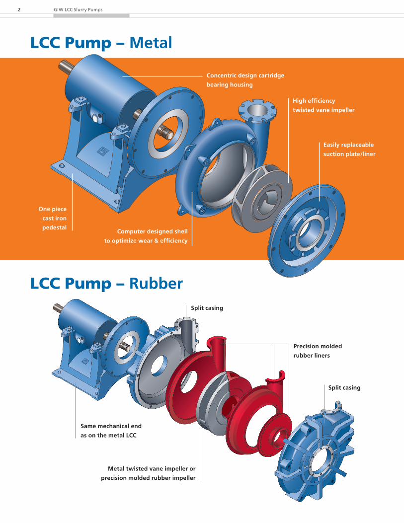
LCC Pump – Metal
GIW LCC Slurry Pumps2
LCC Pump – Rubber
Concentric design cartridge
bearing housing
High efficiency
twisted vane impeller
One piece
cast iron
pedestalComputer designed shell
to optimize wear & efficiency
Easily replaceable
suction plate/liner
Same mechanical end
as on the metal LCC
Metal twisted vane impeller or
precision molded rubber impeller
Precision molded
rubber liners
Split casing
Split casing
With High Performance Corbrasion™ Resistance, the GIW LCC Pump family withstands the most severe slurry applications.
Whatever the duty, it’s no challenge for the pump tailored to take on any slurry pumping condition.
Corbrasive™ Resistant Wet End Parts
• Advanced GIW metallurgy provides Corbrasive™ (corrosion and abrasive wear resistant) alloys tailored to meet virtually any slurry pumping condition.
Advanced Hydraulic Design
• Uses the latest technology tried and tested in GIW’s Hydraulic Laboratory and in the field.
Single Wall Hard Metal shell
• CAD designed shell and replaceable suction plate/liner
• Interchangeable sizes with 2 pedestals and 5 mechanical ends
• GIW alloys available for difficult chemical applications
Rubber Lined
• Precision molded rubber parts
• Bolt in liners for easy maintenance
• CNC machined ductile iron casings
• Two-stage pressure capacity up to 230 psi (16 bar) operating pressure
Extra Heavy Hard Metal
• Heavier metal sections and hydraulics suited to the most severe slurry duties
• Two-stage pressure up to 230 psi (16 bar) operating pressure
• Separate suction liner and non-wearing plate (lower replacement cost)
• Available in sizes 150-500 (6" x 20") and above
Impellers (metal or rubber)
• Twisted three vane design provides high efficiency and low net positive suction head requirements
• Maximum sphere passage
• Available in GIW alloys, polyurethane and extreme duty versions
Also available in rubber:
• completely interchangeable with existing metal impellers used in earlier LCC-R pumps
• best wear resistant rubber on the market
• uses proven advanced hydraulics
• thickened shrouds and vanes provide maximum wear resistance in heavier slurries
Cartridge Bearing Assembly
• CNC machined cast iron cylindrical housing
• Double row tapered roller bearings handle mechanical and thrust forces
• INPRO® Bearing Isolators are standard
• Oil or grease lubrication
Pedestal
• CNC machined cast iron
• Self-aligning concentric bearing supports
• Integrated impeller gap adjustment screw
• Two pedestal sizes for entire LCC range
LCC Metal and Rubber Design Features:
3
Applications: The LCC Pump is a high performance, low maintenance slurry
pump recommended for coarse or fine particles from solids-laden
waste to aggressive slurries of an abrasive and/or corrosive nature.
Size Range:• Discharge diameters:
2 in to 12 in (50 mm to 300 mm)
• Flows: to 17,000 gpm (3200 m³/h)
• Total head: up to 300 ft (90 m)
• Power rating: to 750 HP (560 kW)
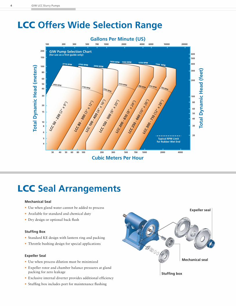
LCC Offers Wide Selection Range
GIW LCC Slurry Pumps4
6 x
8 LS
R 25
8 x
10 L
SR 3
2
10 x
12
LSR
3612
x 1
4 LS
R 36
100 200 300 500 700 1000 2000 4000 6000 10000 20000
30 40 50 60 80 100 200 300 500 700 1000 2000 4000
LCC
50 -
230
(2"
x 9"
)
LCC
80 -
300
(3"
x 12
")
LCC
100
- 400
(4"
x 16
")LC
C 15
0 - 5
00 (6
" x
20")
LCC
200
- 610
(8"
x 24
")
LCC
250
- 660
(10"
x 2
6")
LCC
300
- 710
(12"
x 2
8")
2400 RPM1740 RPM 1355 RPM
1070 RPM 880 RPM810 RPM 750 RPM
3710 RPM 2700 RPM 2090 RPM
1650 RPM 1360 RPM 1250 RPM1160 RPM
Typical RPM Limitfor Rubber Wet End
GIW Pump Selection Chart(for use as a first guide only) 600
500
400
300
200
100
80
60
50
40
30
20
200
150
100
80
60
50
40
30
20
15
10
8
6
5
4
Tota
l Dyn
amic
Hea
d (
feet
)
Tota
l Dyn
amic
Hea
d (
met
ers)
Gallons Per Minute (US)
Cubic Meters Per Hour
LCC Seal ArrangementsMechanical Seal
• Use when gland water cannot be added to process
• Available for standard and chemical duty
• Dry design or optional back flush
Stuffing Box
• Standard KE design with lantern ring and packing
• Throttle bushing design for special applications
Expeller Seal
• Use when process dilution must be minimized
• Expeller rotor and chamber balance pressures at gland packing for zero leakage
• Exclusive internal diverter provides additional efficiency
• Stuffing box includes port for maintenance flushing
Expeller seal
Stuffing box
Mechanical seal

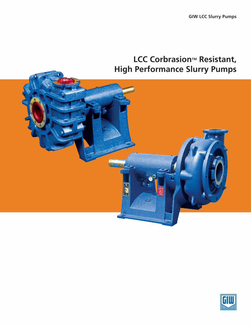
LCC Metal Dimensions
5
1) When assembled with expeller + 2.76 in 2) When assembled with expeller + 3.94 in 3) No expeller
Dimensions in inches (US) [Shaft in mm]
PUMP DIMENSIONS
w3*
w2*
b2
s1
s2
a1
m1m1m2
v
r
c
n
q
a e
f
g
lb1
DN1
DN2 w1*
h2
h1
ISO R773
x
d
t
u (k6 tolerance)
PUMP ANDSHAFT SIZE
PUMP* May exceed h1
DN1 DN2 a a1 b1 b2 f h1 h2 r w1(ref.)
w2(ref.)
w3(ref.)
q(ref.)
50-230 1 3 2 4.53 4.61 1) 0.87 0.79 29.84 1) 14.57 9.06 5.71 6.69 6.89 8.71 1.56
(2" x 9") 2 3 2 4.53 4.61 1) 0.87 0.79 32.09 1) 14.57 9.06 5.71 6.69 6.89 8.71 1.56
80-300 1 4 3 4.72 4.96 1) 0.87 0.87 30.16 1) 14.57 10.63 7.87 8.86 9.45 11.62 1.88
(3" x 12") 2 4 3 4.72 4.96 1) 0.87 0.87 32.40 1) 14.57 10.63 7.87 8.86 9.45 11.62 1.88
100-400 1 6 4 5.32 5.43 1) 0.94 0.94 30.63 1) 14.57 12.80 9.84 11.22 11.81 14.34 2.19
(4" x 16") 2 6 4 5.32 5.43 1) 0.94 0.94 32.87 1) 14.57 12.80 9.84 11.22 11.81 14.34 2.19
3 6 4 5.32 7.91 3) 0.94 0.94 43.19 3) 21.26 12.80 9.84 11.22 11.81 14.34 2.19
150-500 3 8 6 6.89 7.44 2) 1.26 1.06 42.72 2) 21.26 16.14 12.21 14.17 14.76 17.71 2.63
(6" x 20") 4 8 6 6.89 7.44 2) 1.26 1.06 48.23 2) 21.26 16.14 12.21 14.17 14.76 17.71 2.63
200-610 3 10 8 8.27 8.62 2) 1.26 1.26 43.90 2) 21.26 20.08 14.17 16.54 17.32 20.92 3.38
(8" x 24") 4 10 8 8.27 8.62 2) 1.26 1.26 49.41 2) 21.26 20.08 14.17 16.54 17.32 20.92 3.38
5 10 8 8.27 8.62 2) 1.26 1.26 52.56 2) 21.26 20.08 14.17 16.54 17.32 20.92 3.38
250-660 3 12 10 9.65 9.80 2) 1.26 1.26 45.08 2) 21.26 22.05 15.95 18.90 20.08 23.95 3.94
(10" x 26") 4 12 10 9.65 9.80 2) 1.26 1.26 50.59 2) 21.26 22.05 15.95 18.90 20.08 23.95 3.94
5 12 10 9.65 9.80 2) 1.26 1.26 53.74 2) 21.26 22.05 15.95 18.90 20.08 23.95 3.94
300-710 3 14 12 11.42 11.38 2) 1.46 1.26 46.65 2) 21.26 25.20 18.11 22.05 24.02 27.61 3.94
(12" x 28") 4 14 12 11.42 11.38 2) 1.46 1.26 52.17 2) 21.26 25.20 18.11 22.05 24.02 27.61 3.94
5 14 12 11.42 11.38 2) 1.46 1.26 55.32 2) 21.26 25.20 18.11 22.05 24.02 27.61 3.94
SHAFT SIZE PEDESTAL SHAFT END
c e g m1 m2 n s1 s2d
(mm) l t(mm)
u(mm)
v(mm)
x(mm)
1 20.87 19.53 0.79 7.78 1.85 18.90 1.00 1.56 35 4.09 30.3 10 90 8
2 20.87 19.53 0.79 7.78 1.85 18.90 1.00 1.56 50 5.98 44.5 14 100 9
3 31.50 27.40 1.00 11.32 2.60 28.54 1.38 2.00 70 6.77 62.5 20 140 12
4 31.50 27.40 1.00 11.32 2.60 28.54 1.38 2.00 100 10.04 90.0 28 200 16
5 31.50 27.40 1.00 11.32 2.60 28.54 1.38 2.00 125 10.43 113.9 32 200 18
Dimensions in inches (US) [Shaft in mm]
GIW LCC Slurry Pumps6
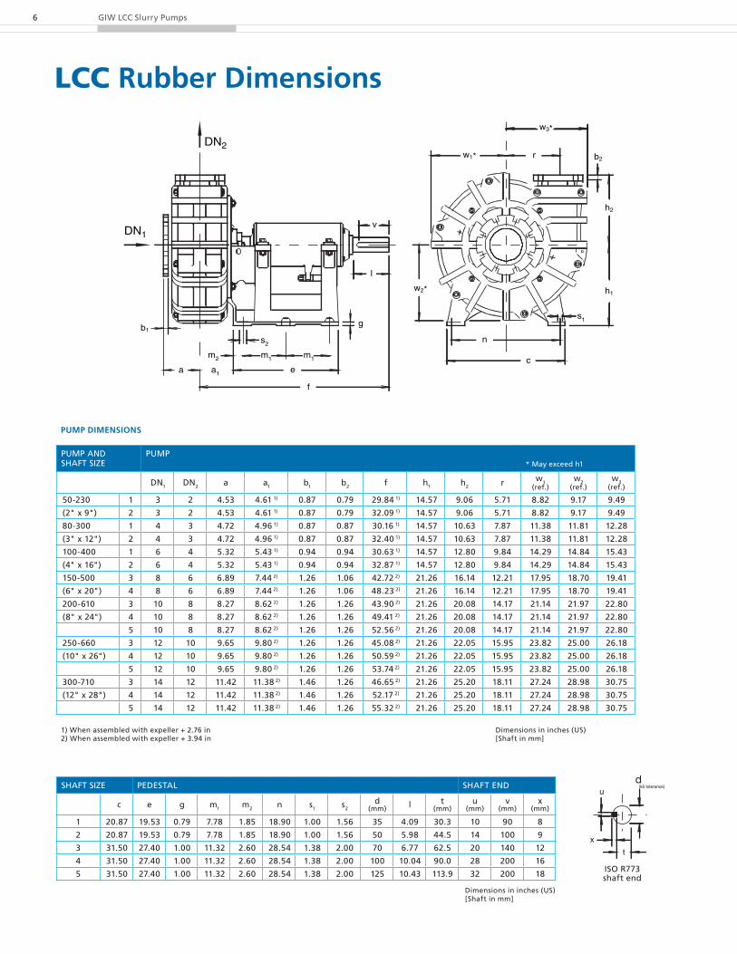
LCC Rubber Dimensionsw3*
w2*
b2
s1
r
c
n
w1*
h2
h1
s2
a1
m1m2
v
a e
f
g
l
DN2
DN1
b1
m1
1) When assembled with expeller + 2.76 in 2) When assembled with expeller + 3.94 in
Dimensions in inches (US) [Shaft in mm]
PUMP DIMENSIONS
PUMP ANDSHAFT SIZE
PUMP* May exceed h1
DN1 DN2 a a1 b1 b2 f h1 h2 r w1(ref.)
w2(ref.)
w3(ref.)
50-230 1 3 2 4.53 4.61 1) 0.87 0.79 29.84 1) 14.57 9.06 5.71 8.82 9.17 9.49
(2" x 9") 2 3 2 4.53 4.61 1) 0.87 0.79 32.09 1) 14.57 9.06 5.71 8.82 9.17 9.49
80-300 1 4 3 4.72 4.96 1) 0.87 0.87 30.16 1) 14.57 10.63 7.87 11.38 11.81 12.28
(3" x 12") 2 4 3 4.72 4.96 1) 0.87 0.87 32.40 1) 14.57 10.63 7.87 11.38 11.81 12.28
100-400 1 6 4 5.32 5.43 1) 0.94 0.94 30.63 1) 14.57 12.80 9.84 14.29 14.84 15.43
(4" x 16") 2 6 4 5.32 5.43 1) 0.94 0.94 32.87 1) 14.57 12.80 9.84 14.29 14.84 15.43
150-500 3 8 6 6.89 7.44 2) 1.26 1.06 42.72 2) 21.26 16.14 12.21 17.95 18.70 19.41
(6" x 20") 4 8 6 6.89 7.44 2) 1.26 1.06 48.23 2) 21.26 16.14 12.21 17.95 18.70 19.41
200-610 3 10 8 8.27 8.62 2) 1.26 1.26 43.90 2) 21.26 20.08 14.17 21.14 21.97 22.80
(8" x 24") 4 10 8 8.27 8.62 2) 1.26 1.26 49.41 2) 21.26 20.08 14.17 21.14 21.97 22.80
5 10 8 8.27 8.62 2) 1.26 1.26 52.56 2) 21.26 20.08 14.17 21.14 21.97 22.80
250-660 3 12 10 9.65 9.80 2) 1.26 1.26 45.08 2) 21.26 22.05 15.95 23.82 25.00 26.18
(10" x 26") 4 12 10 9.65 9.80 2) 1.26 1.26 50.59 2) 21.26 22.05 15.95 23.82 25.00 26.18
5 12 10 9.65 9.80 2) 1.26 1.26 53.74 2) 21.26 22.05 15.95 23.82 25.00 26.18
300-710 3 14 12 11.42 11.38 2) 1.46 1.26 46.65 2) 21.26 25.20 18.11 27.24 28.98 30.75
(12" x 28") 4 14 12 11.42 11.38 2) 1.46 1.26 52.17 2) 21.26 25.20 18.11 27.24 28.98 30.75
5 14 12 11.42 11.38 2) 1.46 1.26 55.32 2) 21.26 25.20 18.11 27.24 28.98 30.75
SHAFT SIZE PEDESTAL SHAFT END
c e g m1 m2 n s1 s2d
(mm) l t(mm)
u(mm)
v(mm)
x(mm)
1 20.87 19.53 0.79 7.78 1.85 18.90 1.00 1.56 35 4.09 30.3 10 90 8
2 20.87 19.53 0.79 7.78 1.85 18.90 1.00 1.56 50 5.98 44.5 14 100 9
3 31.50 27.40 1.00 11.32 2.60 28.54 1.38 2.00 70 6.77 62.5 20 140 12
4 31.50 27.40 1.00 11.32 2.60 28.54 1.38 2.00 100 10.04 90.0 28 200 16
5 31.50 27.40 1.00 11.32 2.60 28.54 1.38 2.00 125 10.43 113.9 32 200 18
Dimensions in inches (US) [Shaft in mm]
ISO R773 shaft end
x
d
t
u (k6 tolerance)
7
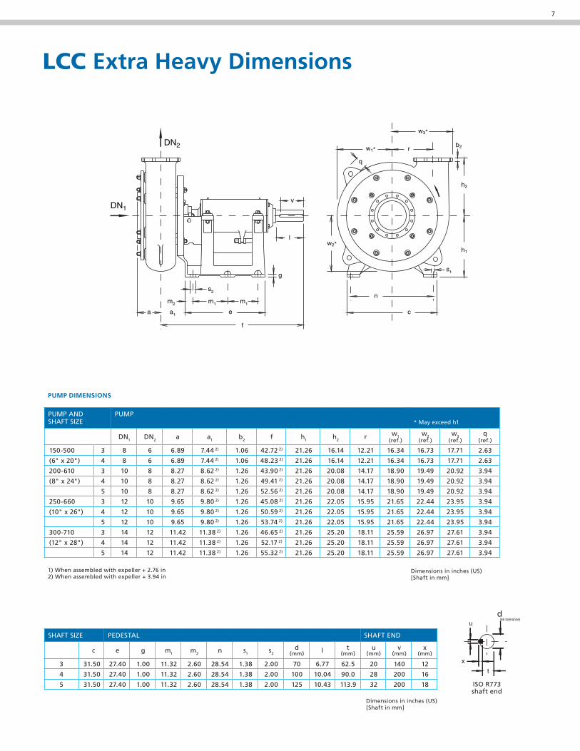
LCC Extra Heavy Dimensions
w3*
w2*
b2
s1
s2
a1
m1m1m2
v
r
c
n
q
a e
f
g
l
DN1
DN2 w1*
h2
h1
1) When assembled with expeller + 2.76 in 2) When assembled with expeller + 3.94 in
Dimensions in inches (US) [Shaft in mm]
PUMP DIMENSIONS
PUMP ANDSHAFT SIZE
PUMP* May exceed h1
DN1 DN2 a a1 b2 f h1 h2 r w1(ref.)
w2(ref.)
w3(ref.)
q(ref.)
150-500 3 8 6 6.89 7.44 2) 1.06 42.72 2) 21.26 16.14 12.21 16.34 16.73 17.71 2.63
(6" x 20") 4 8 6 6.89 7.44 2) 1.06 48.23 2) 21.26 16.14 12.21 16.34 16.73 17.71 2.63
200-610 3 10 8 8.27 8.62 2) 1.26 43.90 2) 21.26 20.08 14.17 18.90 19.49 20.92 3.94
(8" x 24") 4 10 8 8.27 8.62 2) 1.26 49.41 2) 21.26 20.08 14.17 18.90 19.49 20.92 3.94
5 10 8 8.27 8.62 2) 1.26 52.56 2) 21.26 20.08 14.17 18.90 19.49 20.92 3.94
250-660 3 12 10 9.65 9.80 2) 1.26 45.08 2) 21.26 22.05 15.95 21.65 22.44 23.95 3.94
(10" x 26") 4 12 10 9.65 9.80 2) 1.26 50.59 2) 21.26 22.05 15.95 21.65 22.44 23.95 3.94
5 12 10 9.65 9.80 2) 1.26 53.74 2) 21.26 22.05 15.95 21.65 22.44 23.95 3.94
300-710 3 14 12 11.42 11.38 2) 1.26 46.65 2) 21.26 25.20 18.11 25.59 26.97 27.61 3.94
(12" x 28") 4 14 12 11.42 11.38 2) 1.26 52.17 2) 21.26 25.20 18.11 25.59 26.97 27.61 3.94
5 14 12 11.42 11.38 2) 1.26 55.32 2) 21.26 25.20 18.11 25.59 26.97 27.61 3.94
SHAFT SIZE PEDESTAL SHAFT END
c e g m1 m2 n s1 s2d
(mm) l t(mm)
u(mm)
v(mm)
x(mm)
3 31.50 27.40 1.00 11.32 2.60 28.54 1.38 2.00 70 6.77 62.5 20 140 12
4 31.50 27.40 1.00 11.32 2.60 28.54 1.38 2.00 100 10.04 90.0 28 200 16
5 31.50 27.40 1.00 11.32 2.60 28.54 1.38 2.00 125 10.43 113.9 32 200 18
Dimensions in inches (US) [Shaft in mm]
ISO R773 shaft end
x
d
t
u (k6 tolerance)
GIW Industries, Inc.5000 Wrightsboro Road Grovetown, Georgia 30813-2842, USATelephone +1-706-863-1011 Fax +1-706-860-5897www.giwindustries.com
00
00.
00
0 /
03.0
9 /
Tech
nica
l Pap
er /
©
KSB
Akt
ieng
esel
lsch
aft
2009
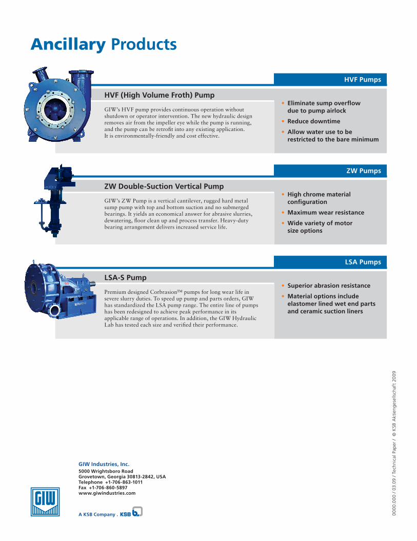
LSA-S Pump
Premium designed Corbrasion™ pumps for long wear life in severe slurry duties. To speed up pump and parts orders, GIW has standardized the LSA pump range. The entire line of pumps has been redesigned to achieve peak performance in its applicable range of operations. In addition, the GIW Hydraulic Lab has tested each size and verified their performance.
LSA Pumps
• Superior abrasion resistance
• Material options include elastomer lined wet end parts and ceramic suction liners
ZW Double-Suction Vertical Pump
GIW’s ZW Pump is a vertical cantilever, rugged hard metal sump pump with top and bottom suction and no submerged bearings. It yields an economical answer for abrasive slurries, dewatering, floor clean up and process transfer. Heavy-duty bearing arrangement delivers increased service life.
ZW Pumps
• High chrome material configuration
• Maximum wear resistance
• Wide variety of motor size options
A KSB Company .
HVF (High Volume Froth) Pump
GIW’s HVF pump provides continuous operation without shutdown or operator intervention. The new hydraulic design removes air from the impeller eye while the pump is running, and the pump can be retrofit into any existing application. It is environmentally-friendly and cost effective.
HVF Pumps
• Eliminate sump overflow due to pump airlock
• Reduce downtime
• Allow water use to be restricted to the bare minimum
Ancillary Products