Embed Size (px)
Citation preview
Load
bre
ak s
wit
ch
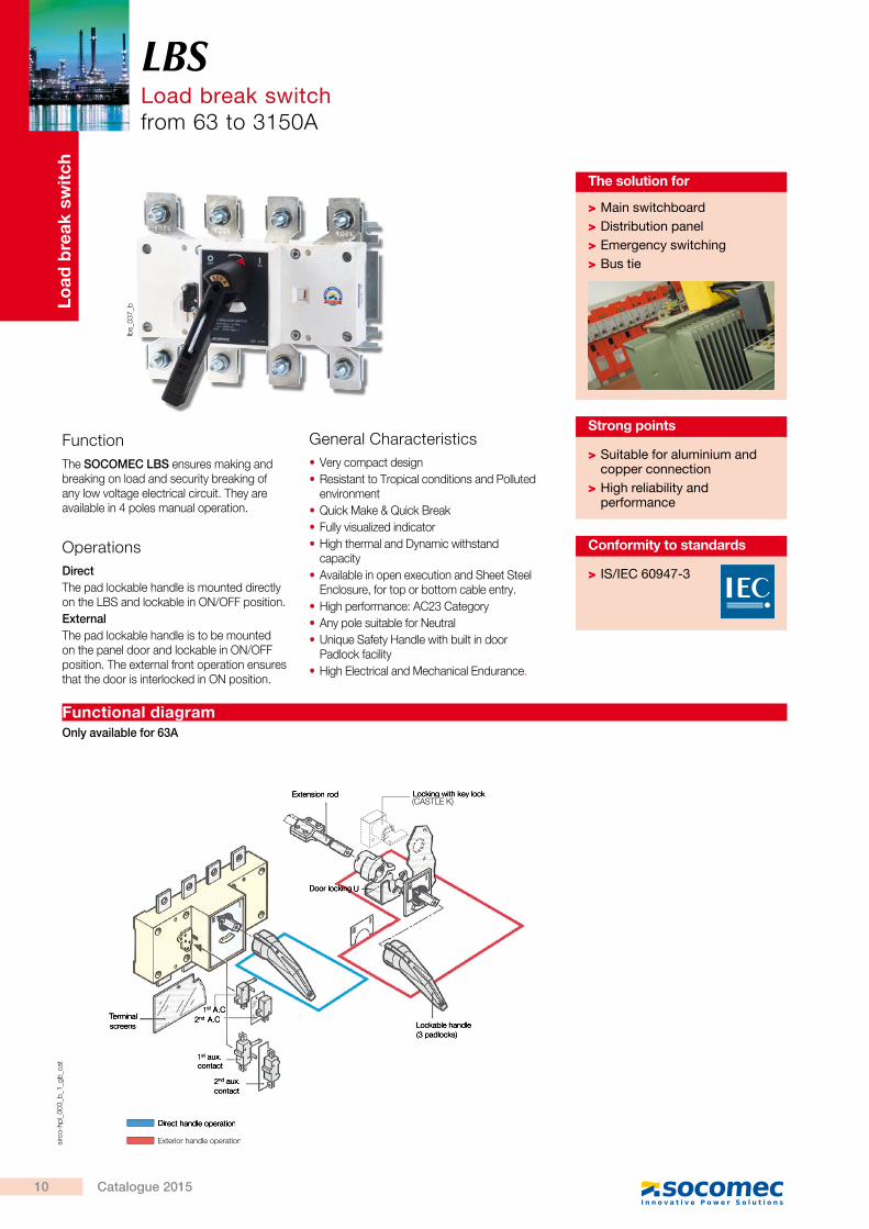
FunctionThe SOCOMEC LBS ensures making and breaking on load and security breaking of any low voltage electrical circuit. They are available in 4 poles manual operation.
OperationsDirectThe pad lockable handle is mounted directly on the LBS and lockable in ON/OFF position.ExternalThe pad lockable handle is to be mounted on the panel door and lockable in ON/OFF position. The external front operation ensures that the door is interlocked in ON position.
General Characteristics • Very compact design • Resistant to Tropical conditions and Polluted environment
• Quick Make & Quick Break • Fully visualized indicator • High thermal and Dynamic withstand capacity
• Available in open execution and Sheet Steel Enclosure, for top or bottom cable entry.
• High performance: AC23 Category • Any pole suitable for Neutral • Unique Safety Handle with built in door Padlock facility
• High Electrical and Mechanical Endurance.
lbs_
037_
b
Extension rod Locking with key lock (CASTELL K)
Door locking U
Lockable handle(3 padlocks)
2nd aux. contact
1st aux. contact
TerminalTerminalTscreens
2nd A.C1st A.C
Direct handle operation
Exterior handle operationsirc
o-hp
l_00
3_b_
1_gb
_cat
LBSLoad break switchfrom 63 to 3150A
> Suitable for aluminium and copper connection
> High reliability and performance
Strong points
Functional diagram
> Main switchboard > Distribution panel > Emergency switching > Bus tie
The solution for
> IS/IEC 60947-3
Conformity to standards
Only available for 63A
(CASTLE K)
LBS Load break switch
from 63 to 3150A
LBSLoad break switchfrom 63 to 3150A
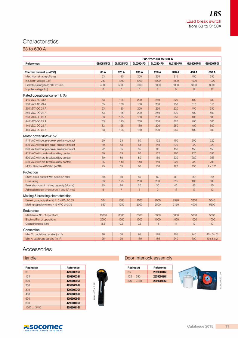
LBS from 63 to 630 AReferences GL00634POI GL01254POI GL02004POI GL02504POI GL03204POI GL04004POI GL06304POI
Thermal current Ith (40°C) 63 A 125 A 200 A 250 A 320 A 400 A 630 A
Max. Normal rating of fuses 63 125 200 250 315 400 630
Insulation voltage Ui (V) 750 1000 1000 1000 1000 1000 1000
Dielectric strength (V) 50 Hz 1 mn. 4000 5000 5000 5000 5000 8000 8000
Impulse voltage (kV) 6 6 6 8 8 12 12
Rated operational current Ie (A) 415 VAC-AC 23 A 63 125 200 250 320 400 630
500 VAC-AC 23 A 55 100 160 200 250 315 315
260 VDC-DC 21 A 63 125 200 250 320 400 630
260 VDC-DC 22 A 63 125 200 250 320 400 500
260 VDC-DC 23 A 63 125 160 200 250 400 500
440 VDC-DC 21 A 63 125 200 250 320 400 500
440 VDC-DC 22 A 63 125 160 200 250 400 500
440 VDC-DC 23 A 63 125 160 200 250 400 500
Motor power (kW) 415V 415 VAC without pre-break auxiliary contact 30 63 80 132 160 200 220
500 VAC without pre-break auxiliary contact 30 63 63 140 220 220 220
690 VAC without pre-break auxiliary contact 22 55 55 90 150 150 150
415 VAC with pre-break auxiliary contact 30 63 80 132 160 220 355
500 VAC with pre-break auxiliary contact 30 80 80 160 220 280 355
690 VAC with pre-break auxiliary contact 35 110 110 110 220 220 295
Motor Reactive 415 VAC (kVAR) 25 55 60 100 125 150 2 x 125
ProtectionShort-circuit current with fuses (kA rms) 80 80 80 80 80 80 80
Fuse rating 63 125 200 250 315 400 630
Peak short-circuit making capacity (kA rms) 15 20 20 30 45 45 45
Admissible short time current 1 sec (kA rms) 5 7 7 9 13 13 13
Making & breaking characteristicsBreaking capacity (A rms) 415 VAC pf-0.35 504 1000 1600 2000 2520 3200 5040
Making capacity (A rms) 415 VAC pf-0.35 630 1250 2000 2500 3150 4000 6300
EnduranceMechanical No. of operations 10000 8000 8000 8000 5000 5000 5000
Electrical No. of operations 2500 1000 1000 1000 1000 1000 1000
Operating force (Nm) 3.5 9.5 9.5 11 11 17 17
ConnectionMin. Cu cable/bus bar size (mm2) 16 50 95 120 185 240 40 x 5 x 2
Min. Al cable/bus bar size (mm2) 25 70 150 185 240 300 40 x 8 x 2
Characteristics63 to 630 A
acce
s_42
7_a_
1_ca
t
Rating (A) Reference
63 42990001GI125 42990003GI200 42990005GI250 42990006GI320 42990007GI400 42990008GI630 42990009GI800 42990010GI1000 … 3150 42990011GI
AccessoriesHandle Door Interlock assembly
acce
s_29
0_a_
1_ca
t
Rating (A) Reference
63 26590001GI125 … 630 26590002GI800 … 3150 26590003GI
10 Catalogue 2015
Load
bre
ak s
wit
ch
FunctionThe SOCOMEC LBS ensures making and breaking on load and security breaking of any low voltage electrical circuit. They are available in 4 poles manual operation.
OperationsDirectThe pad lockable handle is mounted directly on the LBS and lockable in ON/OFF position.ExternalThe pad lockable handle is to be mounted on the panel door and lockable in ON/OFF position. The external front operation ensures that the door is interlocked in ON position.
General Characteristics • Very compact design • Resistant to Tropical conditions and Polluted environment
• Quick Make & Quick Break • Fully visualized indicator • High thermal and Dynamic withstand capacity
• Available in open execution and Sheet Steel Enclosure, for top or bottom cable entry.
• High performance: AC23 Category • Any pole suitable for Neutral • Unique Safety Handle with built in door Padlock facility
• High Electrical and Mechanical Endurance.
lbs_
037_
b
Terminal shTerminal shT rouds
Extension rod Locking with key lock (CASTELL K)
Door locking U
Lockable handle(3 padlocks)
Set of 4 aux. contacts
Set of 3 aux. contacts2nd aux.
contact
1st aux. contact
TerminalTerminalTscreens
2nd A.C1st A.C
Direct handle operation
Exterior handle operationsirc
o-hp
l_00
3_b_
1_gb
_cat
LBSLoad break switchfrom 63 to 3150A
> Suitable for aluminium and copper connection
> High reliability and performance
Strong points
Functional diagram
> Main switchboard > Distribution panel > Emergency switching > Bus tie
The solution for
> IS/IEC 60947-3
Conformity to standards
Only available for 63A
LBS Load break switch
from 63 to 3150A
LBSLoad break switchfrom 63 to 3150A
LBS from 63 to 630 AReferences GL00634POI GL01254POI GL02004POI GL02504POI GL03204POI GL04004POI GL06304POI
Thermal current Ith (40°C) 63 A 125 A 200 A 250 A 320 A 400 A 630 A
Max. Normal rating of fuses 63 125 200 250 315 400 630
Insulation voltage Ui (V) 750 1000 1000 1000 1000 1000 1000
Dielectric strength (V) 50 Hz 1 mn. 4000 5000 5000 5000 5000 8000 8000
Impulse voltage (kV) 6 6 6 8 8 12 12
Rated operational current Ie (A) 415 VAC-AC 23 A 63 125 200 250 320 400 630
500 VAC-AC 23 A 55 100 160 200 250 315 315
260 VDC-DC 21 A 63 125 200 250 320 400 630
260 VDC-DC 22 A 63 125 200 250 320 400 500
260 VDC-DC 23 A 63 125 160 200 250 400 500
440 VDC-DC 21 A 63 125 200 250 320 400 500
440 VDC-DC 22 A 63 125 160 200 250 400 500
440 VDC-DC 23 A 63 125 160 200 250 400 500
Motor power (kW) 415V 415 VAC without pre-break auxiliary contact 30 63 80 132 160 200 220
500 VAC without pre-break auxiliary contact 30 63 63 140 220 220 220
690 VAC without pre-break auxiliary contact 22 55 55 90 150 150 150
415 VAC with pre-break auxiliary contact 30 63 80 132 160 220 355
500 VAC with pre-break auxiliary contact 30 80 80 160 220 280 355
690 VAC with pre-break auxiliary contact 35 110 110 110 220 220 295
Motor Reactive 415 VAC (kVAR) 25 55 60 100 125 150 2 x 125
ProtectionShort-circuit current with fuses (kA rms) 80 80 80 80 80 80 80
Fuse rating 63 125 200 250 315 400 630
Peak short-circuit making capacity (kA rms) 15 20 20 30 45 45 45
Admissible short time current 1 sec (kA rms) 5 7 7 9 13 13 13
Making & breaking characteristicsBreaking capacity (A rms) 415 VAC pf-0.35 504 1000 1600 2000 2520 3200 5040
Making capacity (A rms) 415 VAC pf-0.35 630 1250 2000 2500 3150 4000 6300
EnduranceMechanical No. of operations 10000 8000 8000 8000 5000 5000 5000
Electrical No. of operations 2500 1000 1000 1000 1000 1000 1000
Operating force (Nm) 3.5 9.5 9.5 11 11 17 17
ConnectionMin. Cu cable/bus bar size (mm2) 16 50 95 120 185 240 40 x 5 x 2
Min. Al cable/bus bar size (mm2) 25 70 150 185 240 300 40 x 8 x 2
Characteristics63 to 630 A
acce
s_42
7_a_
1_ca
t
Rating (A) Reference
63 42990001GI125 42990003GI200 42990005GI250 42990006GI320 42990007GI400 42990008GI630 42990009GI800 42990010GI1000 … 3150 42990011GI
AccessoriesHandle Door Interlock assembly
acce
s_29
0_a_
1_ca
t
Rating (A) Reference
63 26590001GI125 … 630 26590002GI800 … 3150 26590003GI
11Catalogue 2015
LBS Load break switch from 63 to 3150A
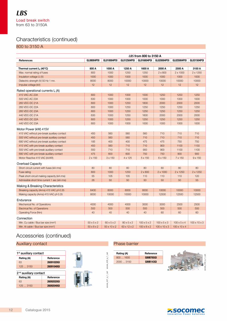
LBS from 800 to 3150 AReferences GL08004POI GL010004POI GL012504POI GL016004POI GL020004POI GL025004POI GL031504POI
Thermal current Ith (40°C) 800 A 1000 A 1250 A 1600 A 2000 A 2500 A 3150 A
Max. normal rating of fuses 800 1000 1250 1250 2 x 800 2 x 1000 2 x 1250
Insulation voltage Ui (V) 1000 1000 1000 1000 1000 1000 1000
Dielectric strength (V) 50 Hz 1 mn. 8000 8000 10000 10000 10000 10000 10000
Impulse voltage (kV) 12 12 12 12 12 12 12
Rated operational currents Ie (A) 415 VAC-AC 23A 800 1000 1000 1000 1250 1250 1250
500 VAC-AC 23A 630 1000 1000 1000 1000 1000 1000
260 VDC-DC 21A 800 1000 1250 1600 2000 2000 2000
260 VDC-DC 22A 800 1000 1250 1250 1250 1250 1250
260 VDC-DC 23A 800 1000 1250 1250 1250 1250 1250
440 VDC-DC 21A 630 1000 1250 1600 2000 2000 2000
440 VDC-DC 22A 800 1000 1250 1250 1250 1250 1250
440 VDC-DC 23A 800 1000 1000 1000 1000 1000 1000
Motor Power (kW) 415V 415 VAC without pre-break auxiliary contact 450 560 560 560 710 710 710
500 VAC without pre-break auxiliary contact 450 560 560 710 710 710 710
690 VAC without pre-break auxiliary contact 185 400 400 475 475 750 750
415 VAC with pre-break auxiliary contact 450 560 710 710 900 1100 1155
500 VAC with pre-break auxiliary contact 550 710 710 900 900 1100 1100
690 VAC with pre-break auxiliary contact 475 600 600 750 750 900 900
Motor Reactive 415 VAC (kVAR) 2 x 150 3 x 150 4 x 125 5 x 150 6 x 150 7 x 150 9 x 150
Overload CapacityShort-circuit current with fuses (kA rms) 80 80 80 80 80 80 80
Fuse rating 800 1000 1250 2 x 800 2 x 1000 2 x 1250 2 x 1250
Peak short-circuit making capacity (kA rms) 55 105 105 110 110 110 120
Admissible short time current 1 sec (kA rms) 26 50 50 50 50 50 55
Making & Breaking CharacteristicsBreaking capacity (Arms) 415 VAC pf-0.35 6400 8000 8000 8000 10000 10000 10000
Making capacity (Arms) 415 VAC pf-0.35 8000 10000 10000 10000 12500 12500 12500
EnduranceMechanical No. of Operations 4000 4000 4000 3000 3000 2500 2500
Electrical No. of Operations 500 500 500 500 500 500 500
Operating Force (Nm) 40 40 40 40 60 60 60
ConnectionMin. Cu cable / Bus bar size (mm2) 50 x 5 x 2 60 x 5 x 2 80 x 5 x 2 100 x 5 x 2 100 x 5 x 3 100 x 5 x 4 100 x 10 x 3
Min. Al cable / Bus bar size (mm2) 50 x 8 x 2 50 x 10 x 2 63 x 12 x 2 100 x 8 x 2 100 x 10 x 3 100 x 10 x 4
800 to 3150 A
Auxiliary contact Phase barrier
Accessories (continued)
acce
s_42
0_a_
1_ca
tac
ces_
421_
a_1_
cat
acce
s_43
2_a_
1_ca
t1st auxiliary contactRating (A) Reference
63 26091020GI125 … 3150 26091040GI
Rating (A) Reference
800 … 1600 G89B765GI2000 … 3150 G89B143GI
2 nd auxiliary contactRating (A) Reference
63 26092020GI125 … 3150 26092040GI
Characteristics (continued)
LBS Load break switch
from 63 to 3150A
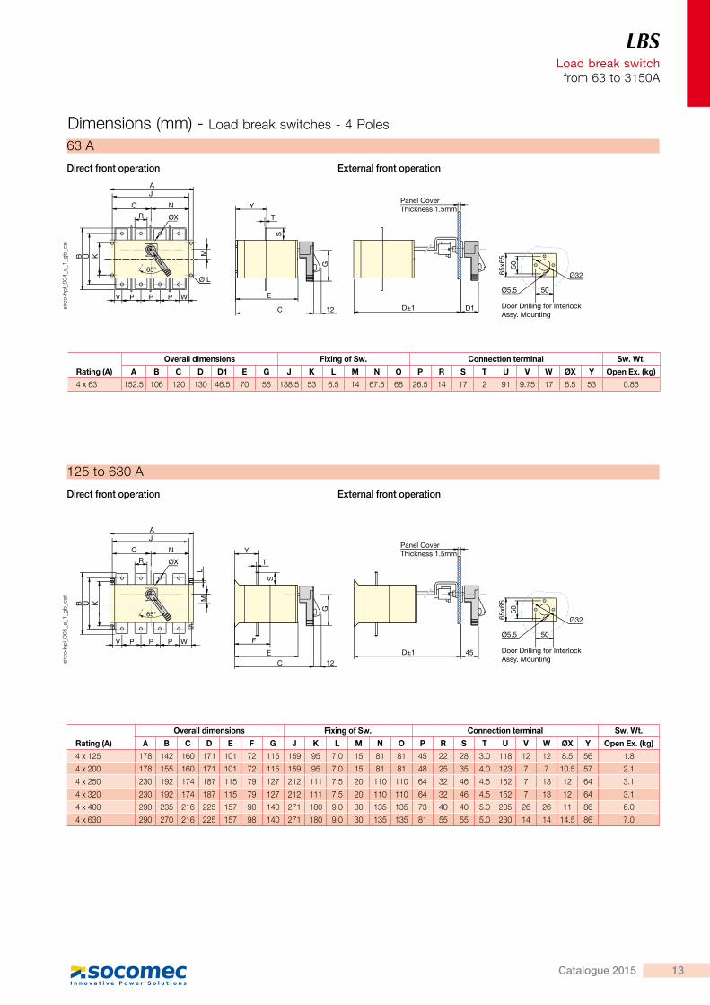
Rating (A)
Overall dimensions Fixing of Sw. Connection terminal Sw. Wt.
A B C D D1 E G J K L M N O P R S T U V W ØX Y Open Ex. (kg)
4 x 63 152.5 106 120 130 46.5 70 56 138.5 53 6.5 14 67.5 68 26.5 14 17 2 91 9.75 17 6.5 53 0.86
AJ
65°
O N
R ØX
B U K
S
G
M
V P P P W E
C 12
Y
T
D±1 D1
Panel CoverThickness 1.5mm
65x6
5
50
Ø32
50Ø5.5
Door Drilling for InterlockAssy. Mounting
Ø L
63 A
Direct front operation External front operation
sirc
o-hp
l_00
4_a_
1_gb
_cat
AJ
65°
O N
R ØX
B U K
S
G
M
V P P P W
EC
F
12
Y
T
D±1 45
Panel CoverThickness 1.5mm
65x6
5
50
Ø32
50Ø5.5
Door Drilling for InterlockAssy. Mounting
L
sirc
o-hp
l_00
5_a_
1_gb
_cat
125 to 630 A
Direct front operation External front operation
Rating (A)
Overall dimensions Fixing of Sw. Connection terminal Sw. Wt.
A B C D E F G J K L M N O P R S T U V W ØX Y Open Ex. (kg)
4 x 125 178 142 160 171 101 72 115 159 95 7.0 15 81 81 45 22 28 3.0 118 12 12 8.5 56 1.8
4 x 200 178 155 160 171 101 72 115 159 95 7.0 15 81 81 48 25 35 4.0 123 7 7 10.5 57 2.1
4 x 250 230 192 174 187 115 79 127 212 111 7.5 20 110 110 64 32 46 4.5 152 7 13 12 64 3.1
4 x 320 230 192 174 187 115 79 127 212 111 7.5 20 110 110 64 32 46 4.5 152 7 13 12 64 3.1
4 x 400 290 235 216 225 157 98 140 271 180 9.0 30 135 135 73 40 40 5.0 205 26 26 11 86 6.0
4 x 630 290 270 216 225 157 98 140 271 180 9.0 30 135 135 81 55 55 5.0 230 14 14 14.5 86 7.0
Dimensions (mm) - Load break switches - 4 Poles
12 Catalogue 2015
LBS Load break switch from 63 to 3150A
LBS from 800 to 3150 AReferences GL08004POI GL010004POI GL012504POI GL016004POI GL020004POI GL025004POI GL031504POI
Thermal current Ith (40°C) 800 A 1000 A 1250 A 1600 A 2000 A 2500 A 3150 A
Max. normal rating of fuses 800 1000 1250 1250 2 x 800 2 x 1000 2 x 1250
Insulation voltage Ui (V) 1000 1000 1000 1000 1000 1000 1000
Dielectric strength (V) 50 Hz 1 mn. 8000 8000 10000 10000 10000 10000 10000
Impulse voltage (kV) 12 12 12 12 12 12 12
Rated operational currents Ie (A) 415 VAC-AC 23A 800 1000 1000 1000 1250 1250 1250
500 VAC-AC 23A 630 1000 1000 1000 1000 1000 1000
260 VDC-DC 21A 800 1000 1250 1600 2000 2000 2000
260 VDC-DC 22A 800 1000 1250 1250 1250 1250 1250
260 VDC-DC 23A 800 1000 1250 1250 1250 1250 1250
440 VDC-DC 21A 630 1000 1250 1600 2000 2000 2000
440 VDC-DC 22A 800 1000 1250 1250 1250 1250 1250
440 VDC-DC 23A 800 1000 1000 1000 1000 1000 1000
Motor Power (kW) 415V 415 VAC without pre-break auxiliary contact 450 560 560 560 710 710 710
500 VAC without pre-break auxiliary contact 450 560 560 710 710 710 710
690 VAC without pre-break auxiliary contact 185 400 400 475 475 750 750
415 VAC with pre-break auxiliary contact 450 560 710 710 900 1100 1155
500 VAC with pre-break auxiliary contact 550 710 710 900 900 1100 1100
690 VAC with pre-break auxiliary contact 475 600 600 750 750 900 900
Motor Reactive 415 VAC (kVAR) 2 x 150 3 x 150 4 x 125 5 x 150 6 x 150 7 x 150 9 x 150
Overload CapacityShort-circuit current with fuses (kA rms) 80 80 80 80 80 80 80
Fuse rating 800 1000 1250 2 x 800 2 x 1000 2 x 1250 2 x 1250
Peak short-circuit making capacity (kA rms) 55 105 105 110 110 110 120
Admissible short time current 1 sec (kA rms) 26 50 50 50 50 50 55
Making & Breaking CharacteristicsBreaking capacity (Arms) 415 VAC pf-0.35 6400 8000 8000 8000 10000 10000 10000
Making capacity (Arms) 415 VAC pf-0.35 8000 10000 10000 10000 12500 12500 12500
EnduranceMechanical No. of Operations 4000 4000 4000 3000 3000 2500 2500
Electrical No. of Operations 500 500 500 500 500 500 500
Operating Force (Nm) 40 40 40 40 60 60 60
ConnectionMin. Cu cable / Bus bar size (mm2) 50 x 5 x 2 60 x 5 x 2 80 x 5 x 2 100 x 5 x 2 100 x 5 x 3 100 x 5 x 4 100 x 10 x 3
Min. Al cable / Bus bar size (mm2) 50 x 8 x 2 50 x 10 x 2 63 x 12 x 2 100 x 8 x 2 100 x 10 x 3 100 x 10 x 4
800 to 3150 A
Auxiliary contact Phase barrier
Accessories (continued)
acce
s_42
0_a_
1_ca
tac
ces_
421_
a_1_
cat
acce
s_43
2_a_
1_ca
t1st auxiliary contactRating (A) Reference
63 26091020GI125 … 3150 26091040GI
Rating (A) Reference
800 … 1600 G89B765GI2000 … 3150 G89B143GI
2 nd auxiliary contactRating (A) Reference
63 26092020GI125 … 3150 26092040GI
Characteristics (continued)
LBS Load break switch
from 63 to 3150A
Rating (A)
Overall dimensions Fixing of Sw. Connection terminal Sw. Wt.
A B C D D1 E G J K L M N O P R S T U V W ØX Y Open Ex. (kg)
4 x 63 152.5 106 120 130 46.5 70 56 138.5 53 6.5 14 67.5 68 26.5 14 17 2 91 9.75 17 6.5 53 0.86
AJ
65°
O N
R ØX
B U K
S
G
M
V P P P W E
C 12
Y
T
D±1 D1
Panel CoverThickness 1.5mm
65x6
5
50
Ø32
50Ø5.5
Door Drilling for InterlockAssy. Mounting
Ø L
63 A
Direct front operation External front operation
sirc
o-hp
l_00
4_a_
1_gb
_cat
AJ
65°
O N
R ØX
B U K
S
G
M
V P P P W
EC
F
12
Y
T
D±1 45
Panel CoverThickness 1.5mm
65x6
5
50
Ø32
50Ø5.5
Door Drilling for InterlockAssy. Mounting
L
sirc
o-hp
l_00
5_a_
1_gb
_cat
125 to 630 A
Direct front operation External front operation
Rating (A)
Overall dimensions Fixing of Sw. Connection terminal Sw. Wt.
A B C D E F G J K L M N O P R S T U V W ØX Y Open Ex. (kg)
4 x 125 178 142 160 171 101 72 115 159 95 7.0 15 81 81 45 22 28 3.0 118 12 12 8.5 56 1.8
4 x 200 178 155 160 171 101 72 115 159 95 7.0 15 81 81 48 25 35 4.0 123 7 7 10.5 57 2.1
4 x 250 230 192 174 187 115 79 127 212 111 7.5 20 110 110 64 32 46 4.5 152 7 13 12 64 3.1
4 x 320 230 192 174 187 115 79 127 212 111 7.5 20 110 110 64 32 46 4.5 152 7 13 12 64 3.1
4 x 400 290 235 216 225 157 98 140 271 180 9.0 30 135 135 73 40 40 5.0 205 26 26 11 86 6.0
4 x 630 290 270 216 225 157 98 140 271 180 9.0 30 135 135 81 55 55 5.0 230 14 14 14.5 86 7.0
Dimensions (mm) - Load break switches - 4 Poles
13Catalogue 2015
LBS Load break switch from 63 to 3150A
Handle for 1000A-1600AHandle for 800A
4xØ9 800A
Ø15
8.5 8.510
5033
33
1000/1250A16x11
19
25
25 171963
1600A
20
4xØ13
204080
2040
Connection terminal
65x6
5
50
Ø32
50Ø5.5
Door Drilling for InterlockAssy. Mounting
AJ
O N
R ØX
B U K
M
V P P P W
L
S
G
EC
F
14
Y
T
D±1 81
Panel CoverThickness 1.5mm
sirc
o-hp
l_00
6_a_
1_gb
_cat
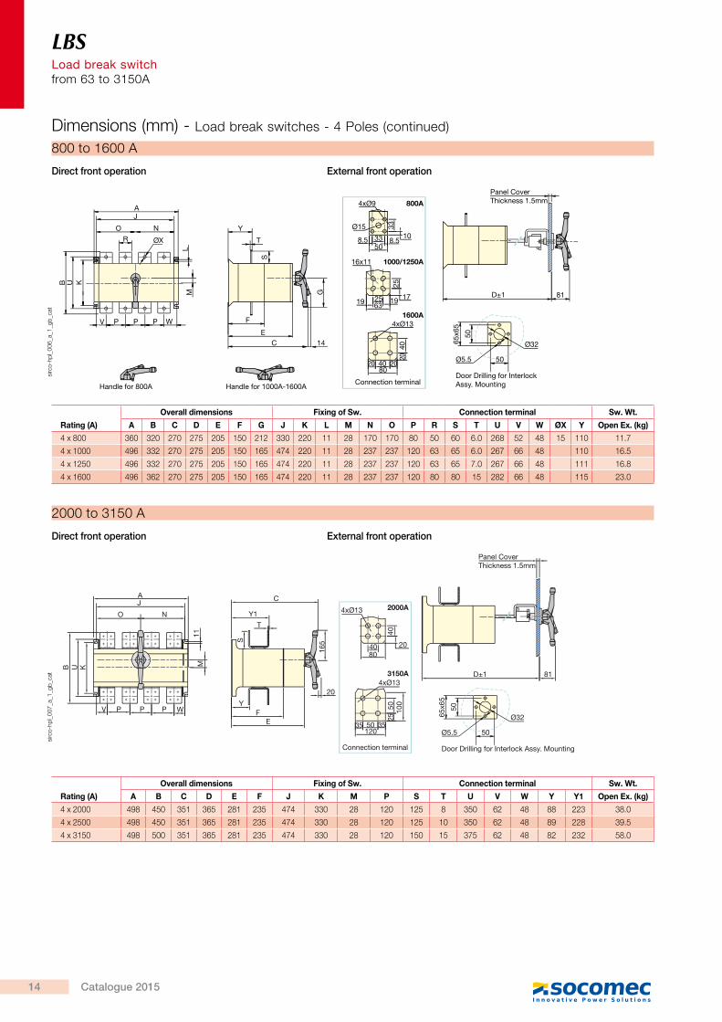
800 to 1600 A
Direct front operation External front operation
Rating (A)
Overall dimensions Fixing of Sw. Connection terminal Sw. Wt.
A B C D E F G J K L M N O P R S T U V W ØX Y Open Ex. (kg)
4 x 800 360 320 270 275 205 150 212 330 220 11 28 170 170 80 50 60 6.0 268 52 48 15 110 11.7
4 x 1000 496 332 270 275 205 150 165 474 220 11 28 237 237 120 63 65 6.0 267 66 48 110 16.5
4 x 1250 496 332 270 275 205 150 165 474 220 11 28 237 237 120 63 65 7.0 267 66 48 111 16.8
4 x 1600 496 362 270 275 205 150 165 474 220 11 28 237 237 120 80 80 15 282 66 48 115 23.0
Panel CoverThickness 1.5mm
Connection terminal
AJ
O N
11
B KU
V P WPP
C
Y1
T
S
YF
E
20
165
M
4xØ13 2000A
8040 20
40
3150A4xØ13
35 3550120
2550 10
0
D±1 81
65x6
5
50
Ø32
50Ø5.5
Door Drilling for Interlock Assy. Mounting
sirc
o-hp
l_00
7_a_
1_gb
_cat
2000 to 3150 A
Direct front operation External front operation
Rating (A)
Overall dimensions Fixing of Sw. Connection terminal Sw. Wt.
A B C D E F J K M P S T U V W Y Y1 Open Ex. (kg)
4 x 2000 498 450 351 365 281 235 474 330 28 120 125 8 350 62 48 88 223 38.0
4 x 2500 498 450 351 365 281 235 474 330 28 120 125 10 350 62 48 89 228 39.5
4 x 3150 498 500 351 365 281 235 474 330 28 120 150 15 375 62 48 82 232 58.0
Dimensions (mm) - Load break switches - 4 Poles (continued)
Load
bre
ak s
wit
ch
FunctionSocomec enclosures incorporate four pole manually operated load break switches which can make and break on load and provide isolation for any low voltage electrical circuit. The enclosure provides protection against contact with live parts as well asenvironmental factors such as dust, water and other hazards. • On load switch ON and OFF • Emergency breaking • Safe and local isolation of downstream loads for maintenance purpose
Enclosed LBSLoad break switchfrom 63 to 1600 A
H
W X
LY
coff_
379_
a_1_
x_ca
t
General Characteristics • Adapted to environments subject to chemical, dust, contamination and atmospheric corrosion risks.
• CRCA sheet (Door 1.2 mm, Body 1.6 mm) • Colour shade: RAL 7035 coating of epoxy polyester powder 70 micron
• 2 external earthing points on each side. • Wall mounted with 4 bolts • Door locking system allows opening of door only in off position
• Incoming & outgoing easily interchangeable at site
• Removable plate top & bottom • Door with solid hinges.
References & dimensions
Rating (A) ReferenceL
(mm)W
(mm)X
(mm)Y
(mm)H
(mm)
63 GL00634POI 180 200 160 210 126
125 GL01254POI 260 250 213 285 195
200 GL02004POI 260 250 213 285 195
250 GL02504POI 345 320 275 375 210
320 GL03204POI 345 320 275 375 210
400 GL04004POI 395 370 320 420 250
630 GL06304POI 395 370 320 420 250
800 GL08004POI 500 470 422 550 307
1000 GL10004POI 630 510 435 675 307
1250 GL12504POI 630 510 435 675 307
1600 GL16004POI 630 510 435 675 307
For ratings above 1600A, please contact us.
> Suitable for aluminium and copper connection
> High reliability and performance AC-23
> Complete range up to 3150 A
Strong points
> OEM > Industries > Service Sector Building > Power distribution
The solution for
AdvantagesSafety of operationsDoor interlocking and positive break indication provide increased safety for the operator.Inductive load breaking (AC23)This enclosure range is provided withLoad Break switches which are adapted to highly inductive loads.Complete rangeThe range offers a wide variety of variantsdepending on the number of poles, rating and enclosure type.
> IS/IEC 60947-3
Conformity to standards
coff_
461_
a
coff_
456_
a
14 Catalogue 2015