Embed Size (px)
Citation preview
MODEL 710Ground Support Intercom
INSTALLATION/OPERATION MANUAL


TABLE OF CONTENTS
Overview . . . . . . . . . . . . . . . . . . . . . . . . . . . . . . . . . . . . . . . . . . . . . . . . . . . . . . . . . . . . . . . . . . . . . . . . . . . . . . . 2
Features . . . . . . . . . . . . . . . . . . . . . . . . . . . . . . . . . . . . . . . . . . . . . . . . . . . . . . . . . . . . . . . . . . . . . . . . . . . . . . . . 3
Installation . . . . . . . . . . . . . . . . . . . . . . . . . . . . . . . . . . . . . . . . . . . . . . . . . . . . . . . . . . . . . . . . . . . . . . . . . . . . 4-7
Operation . . . . . . . . . . . . . . . . . . . . . . . . . . . . . . . . . . . . . . . . . . . . . . . . . . . . . . . . . . . . . . . . . . . . . . . . . . . . . . 7
Troubleshooting . . . . . . . . . . . . . . . . . . . . . . . . . . . . . . . . . . . . . . . . . . . . . . . . . . . . . . . . . . . . . . . . . . . . . . . 8-9
Options and Accessories . . . . . . . . . . . . . . . . . . . . . . . . . . . . . . . . . . . . . . . . . . . . . . . . . . . . . . . . . . . . . . . . . 10
Appendix A-Wiring Diagrams . . . . . . . . . . . . . . . . . . . . . . . . . . . . . . . . . . . . . . . . . . . . . . . . . . . . . . . . . . . . 10
Appendix B-RJ Connector Assembly . . . . . . . . . . . . . . . . . . . . . . . . . . . . . . . . . . . . . . . . . . . . . . . . . . . . . . 11
Warranty . . . . . . . . . . . . . . . . . . . . . . . . . . . . . . . . . . . . . . . . . . . . . . . . . . . . . . . . . . . . . . . . . . . . . . . . . . . . . . 12
1

2
OVERVIEW
Flightcom’s 710 intercom is designed for use in rugged, demanding environments. Providing clear communicationsbetween up to three occupants and a 2-way radio, it is ideal for mobile equipment with complex internal andexternal communication requirements and high-noise environments. When used with Flightcom noise attenuatingheadsets, the system provides protection from hearing loss that occurs from exposure to high-noise levels. The710 intercom is a durable solution for airport ground support applications.
Headsets used with the 710 intercom system are interchangeable with other airport ground support systemsthat utilize the same standard three conductor plug configuration. All headset users experience simultaneousfull-duplex, hands-free communications when used with the 710 intercom system. Individual headsets determineaudio transmission with the push of a button, as well as independent volume control.
When connected to a radio, all participants will hear the radio traffic and only those set up to transmit will trans-mit over the radio.

Modular JacksThe modular jacks are the connection points for headset jacks or headset modules.
Radio Interface JackThe 9-pin D-Sub connector is an attachment point for the enclosed mobile radio (MR) interface cable option.
Power ConnectorThe 3-pin connector is for attachment to vehicle power. A power connection cable is provided.
Receive Audio AdjustA rotational adjustment for setting the level of audio received to the intercom from a mobile radio.
Transmit Audio Gain Jump / Intercom Audio Gain JumpTwo dip switches are provided for incremental gain increases of both the radio transmit audio and the intercom audio.
Transmit Audio AdjustA rotational adjustment for setting the level of audio transmitted to an appropriate level for a mobile radio.
3
INTERCOM
PR
FEATURES
RADIO POWER
Rx T/G Tx
Modular Jacks
Radio Interface JackPower Connector
Receive Audio Adjust Transmit Audio Adjust
Transmit Audio Gain JumpIntercom Audio Gain Jump
Front View
Back View
Side View

4
INSTALLATION
Mounting the Intercom
Mount the intercom unit to a flat surface by drilling four mounting holes and installing the enclosed #6 fasteners.Mounting hole and intercom dimensions are shown below. The unit is designed for indoor and vehicle interioruse. Do not mount outdoors.
Assembly Shown without JacksUnits: Inches [millimeters]Scale: None
5
INSTALLATION
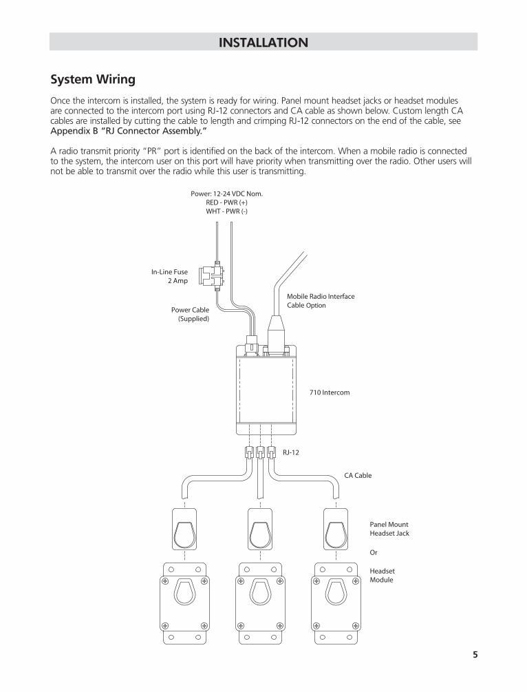
System Wiring
Once the intercom is installed, the system is ready for wiring. Panel mount headset jacks or headset modules are connected to the intercom port using RJ-12 connectors and CA cable as shown below. Custom length CA cables are installed by cutting the cable to length and crimping RJ-12 connectors on the end of the cable, seeAppendix B “RJ Connector Assembly.”
A radio transmit priority “PR” port is identified on the back of the intercom. When a mobile radio is connectedto the system, the intercom user on this port will have priority when transmitting over the radio. Other users willnot be able to transmit over the radio while this user is transmitting.

6
INSTALLATION
A mobile radio may be connected to the intercom by using the radio port on the back of the unit. A MR interface cable, with an un-terminated end, is supplied with the intercom. For independent wire descriptions,see Appendix A.
Warning To ensure proper operation, the connection to the radio should be performed by a qualified radio technician.
Some radio specific interface cables are available for common model radios. For a list of interface cables, pleasevisit www.flightcom.net and click on the Ground Support section of our web site or contact our service depart-ment at 800-432-4342, ext.130. When installing an MR cable, tighten the two screws on the plug of the cable.
Warning If the screws are not properly tightened, the 9-pin plug may vibrate loose and cause problemswith transmission, reception, or other radio functionality.
Power is wired to the intercom using the enclosed power supply cable with in-line fuse. See “System Wiring” inthe Installation section of this manual. When routing the power cable, the in-line fuse should be easy to access.
WarningBefore making the power connections, make sure the power source is turned off.
For additional wiring detail, see Appendix A.
Setting Options
Several adjustments to the 710 intercom are required. When connecting to a mobile radio it will be necessary tomake both transmit and receive audio adjustments.
WarningThese adjustments must be performed by a qualified radio technician. Failure to perform these adjustments may result in problems hearing or transmitting radio signals when using the intercom system.
Rx T/G Tx
Receive Audio Adjust Transmit Audio Adjust
Transmit Audio Gain JumpIntercom Audio Gain Jump

7
INSTALLATION
RXThe Receive Audio Adjustment is a rotational adjustment of the audio gain from the radio. When making thisadjustment, set your mobile radio volume to the normal volume level used without an intercom installed. Theaudio level should be adjusted with other intercom users for quality audio mixing.
Transmit Audio Gain JumpThe Transmit Audio Gain Jump switch is an incremental gain increase of the audio broadcast through the radio.The gain is increased when the switch is in the “up” position and decreased in the “down” position. TheTransmit Audio “TX” should be used initially for adjustment and the Transmit Audio Gain Jump used only ifrequired.
Intercom Audio Gain JumpThe Intercom Audio Gain Jump switch is an incremental gain increase of the intercom sound level. While eachheadset is equipped with an independent volume control, an overall higher intercom sound level is achieved usingthe Intercom Audio Gain Jump switch. The gain is increased when the switch is in the “up” position anddecreased in the “down” position.
TXThe Transmit Audio Adjustment is a rotational adjustment of the audio broadcast through the radio. Adjust theradio transmit sound level to other radio sound levels to eliminate clipping and to provide quality audio mixing.
After these adjustments are made, the access holes may be sealed using the enclosed plugs.
The 710 intercom is designed to offer hands-free, full-duplex communication between participants. In addition,mobile radio communication is possible when connected to Flightcom’s 710 intercom.
Before testing the intercom, make sure that the power supplied to the intercom is turned on. If a radio is con-nected to the intercom, confirm that it has power as well.
To begin using the intercom, plug your Flightcom headset into a headset jack or headset module. For proper fitting instructions, as well as care and maintenance, see your headset manual.
While speaking into your headset microphone, and using the Push-To-Talk (PTT) button on the headset, you will hear yourself through the headset speakers. Volume may be adjusted on the headset ear dome. Transmittingaudio to other intercom users is done using the PTT button on the headset. PTT buttons are offered in bothlatching and momentary styles. See your headset manual for PTT button identification. Latching buttons are activated by pressing once; allowing constant transmission when “on” and no transmission when “off.”Momentary buttons require constant activation pressure for transmission.
When a mobile radio is connected to the intercom, radio traffic will be heard in the headset speaker. The volumelevel of the radio traffic should be similar to the intercom audio volume level. See the Installation section of thismanual for adjustment. To transmit over the radio, press and hold the radio PTT button while speaking into theheadset microphone. If an optional foot switch is installed, press and hold the foot switch down to transmit overthe radio.
One of the three headset intercom ports on the intercom is a radio transmit priority “PR” port. See “SystemWiring” in the Installation section of this manual. When a mobile radio is connected to the system, the inter-com user on this port will have priority when transmitting over the radio. Other users will not be able to transmitover the radio while this user is transmitting.
OPERATION
TROUBLESHOOTING
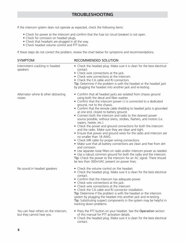
If the intercom system does not operate as expected, check the following items:
• Check for power at the intercom and confirm that the fuse (or circuit breaker) is not open.• Check for corrosion on headset plugs.• Check that headsets are plugged in all the way.• Check headset volume control and PTT button.
If these steps do not correct the problem, review the chart below for symptoms and recommendations.
SYMPTOM RECOMMENDED SOLUTION
Intermittent crackling in headset • Check the headset plug. Make sure it is clean for the best electrical speakers contact.
• Check wire connections at the jack.• Check wire connections at the intercom.• Check the CA cable and RJ connectors.Tip: Determine if the problem is with the headset or the headset jack by plugging the headset into another jack and re-testing.
Alternator whine & other distracting • Confirm that all headset jacks are isolated from chassis ground noises using both the decal and fiber washer.
• Confirm that the intercom power (-) is connected to a dedicated ground, not to the chassis.
• Confirm that the remote cable shielding to headset jacks is groundedat one end, closest to battery ground.
• Connect both the intercom and radio to the cleanest power source possible, without sirens, strobes, flashers, and motors (i.e. wipers, heater, etc.).
• Check the power and ground connections for both the intercom and the radio. Make sure they are clean and tight.
• Ensure that power and ground wires for the radio and intercom areno smaller than 18 AWG.
• Check MR cable for proper wiring connections.• Make sure that all battery connections are clean and free from dirt
and corrosion.• Use separate noise filters on radio and/or intercom power as needed.• Use a robust common ground for both the radio and the intercom.Tip: Check the power to the intercom for an AC signal. There should be less than 300mVAC present on power lines.
No sound in headset speakers • Check the volume control on the headset.• Check the headset plug. Make sure it is clean for the best electrical
contact.• Confirm that the intercom has adequate power.• Check wire connections at the jack.• Check wire connections at the intercom.• Check the CA cable and RJ connector installation.Tip: Determine if the problem is with the headset or the intercom system by plugging the headset into another jack and re-testing.Tip: Substituting suspect components in the system may be helpful in tracking down problems.
You can hear others on the intercom, • Press the PTT button on your headset. See the Operation sectionbut they cannot hear you of this manual for PTT activation details.
• Check the headset plug. Make sure it is clean for the best electrical contact.
8
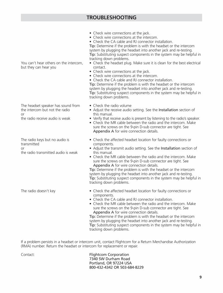
TROUBLESHOOTING
• Check wire connections at the jack.• Check wire connections at the intercom.• Check the CA cable and RJ connector installation.Tip: Determine if the problem is with the headset or the intercom system by plugging the headset into another jack and re-testing.Tip: Substituting suspect components in the system may be helpful in tracking down problems.
You can’t hear others on the intercom, • Check the headset plug. Make sure it is clean for the best electricalbut they can hear you contact.
• Check wire connections at the jack.• Check wire connections at the intercom.• Check the CA cable and RJ connector installation.Tip: Determine if the problem is with the headset or the intercom system by plugging the headset into another jack and re-testing.Tip: Substituting suspect components in the system may be helpful in tracking down problems.
The headset speaker has sound from • Check the radio volumethe intercom but not the radio • Adjust the receive audio setting. See the Installation section ofor this manual.the radio receive audio is weak • Verify that receive audio is present by listening to the radio’s speaker.
• Check the MR cable between the radio and the intercom. Makesure the screws on the 9-pin D-sub connector are tight. See Appendix A for wire connection details.
The radio keys but no audio is • Check the affected headset location for faulty connections or transmitted components.or • Adjust the transmit audio setting. See the Installation section of the radio transmitted audio is weak this manual.
• Check the MR cable between the radio and the intercom. Make sure the screws on the 9-pin D-sub connector are tight. See Appendix A for wire connection details.
Tip: Determine if the problem is with the headset or the intercom system by plugging the headset into another jack and re-testing.Tip: Substituting suspect components in the system may be helpful in tracking down problems.
The radio doesn’t key • Check the affected headset location for faulty connections or components.
• Check the CA cable and RJ connector installation.• Check the MR cable between the radio and the intercom. Make
sure the screws on the 9-pin D-sub connector are tight. See Appendix A for wire connection details.
Tip: Determine if the problem is with the headset or the intercom system by plugging the headset into another jack and re-testing.Tip: Substituting suspect components in the system may be helpful in tracking down problems.
If a problem persists in a headset or intercom unit, contact Flightcom for a Return Merchandise Authorization(RMA) number. Return the headset or intercom for replacement or repair.
Contact: Flightcom Corporation7340 SW Durham RoadPortland, OR 97224 USA800-432-4342 OR 503-684-8229
9
10
OPTIONS AND ACCESSORIES
See www.flightcom.net for options and accessories.
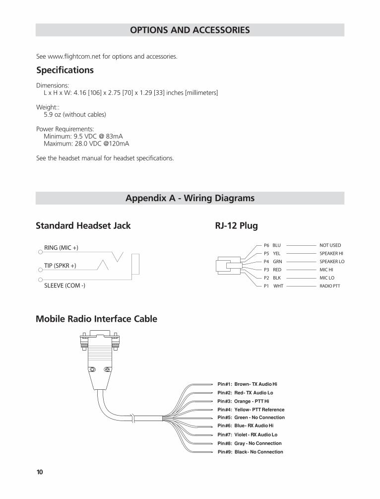
Specifications
Dimensions:L x H x W: 4.16 [106] x 2.75 [70] x 1.29 [33] inches [millimeters]
Weight::5.9 oz (without cables)
Power Requirements:Minimum: 9.5 VDC @ 83mAMaximum: 28.0 VDC @120mA
See the headset manual for headset specifications.
Appendix A - Wiring Diagrams
Standard Headset Jack RJ-12 Plug
Mobile Radio Interface Cable
Pin#1: Brown- TX Audio Hi
Pin#2: Red- TX Audio Lo
Pin#3: Orange - PTT Hi
Pin#4: Yellow- PTT Reference
Pin#5: Green - No Connection
No Connection
No Connection
Pin#6: Blue- RX Audio Hi
Pin#7: Violet - RX Audio Lo
Pin#8: Gray -
Pin#9: Black-
11
Appendix B - RJ Connector Assembly
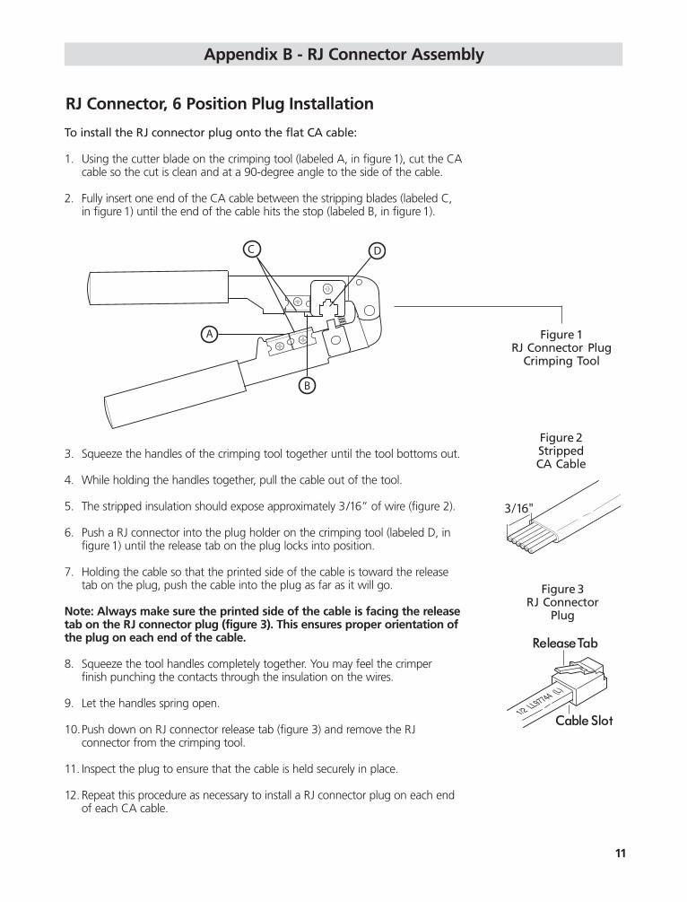
RJ Connector, 6 Position Plug Installation
To install the RJ connector plug onto the flat CA cable:
1. Using the cutter blade on the crimping tool (labeled A, in figure 1), cut the CAcable so the cut is clean and at a 90-degree angle to the side of the cable.
2. Fully insert one end of the CA cable between the stripping blades (labeled C, in figure 1) until the end of the cable hits the stop (labeled B, in figure 1).
3. Squeeze the handles of the crimping tool together until the tool bottoms out.
4. While holding the handles together, pull the cable out of the tool.
5. The stripped insulation should expose approximately 3/16” of wire (figure 2).
6. Push a RJ connector into the plug holder on the crimping tool (labeled D, in figure 1) until the release tab on the plug locks into position.
7. Holding the cable so that the printed side of the cable is toward the release tab on the plug, push the cable into the plug as far as it will go.
Note: Always make sure the printed side of the cable is facing the releasetab on the RJ connector plug (figure 3). This ensures proper orientation ofthe plug on each end of the cable.
8. Squeeze the tool handles completely together. You may feel the crimper finish punching the contacts through the insulation on the wires.
9. Let the handles spring open.
10.Push down on RJ connector release tab (figure 3) and remove the RJ connector from the crimping tool.
11. Inspect the plug to ensure that the cable is held securely in place.
12. Repeat this procedure as necessary to install a RJ connector plug on each end of each CA cable.
Figure 1RJ Connector Plug
Crimping Tool
Figure 2Stripped CA Cable
Figure 3RJ Connector
Plug

WARRANTY
One-Year Limited Warranty to the Original Purchaser
Flightcom Corporation warrants to the original purchaser of this product that it will be free from defects in materials and workmanship, under normal and proper use, for the period of one year from date of purchase.Flightcom Corporation will repair or replace, at its sole option, any parts showing factory defects during this warranty period, subject to the following provisions. This warranty applies only to a new product which has beensold through authorized channels of distribution. All work under warranty must be performed by FlightcomCorporation. For warranty service, all products must be shipped to our address, freight prepaid, accompanied bya dated proof of purchase. SAVE YOUR SALES SLIP! The purchaser voids this warranty if he, she or others attemptto repair, service or alter the product in anyway. This warranty does not apply in the event of accident, abuse,improper installation, unauthorized repair, tampering, modification, fire, flood, collision or other damage fromexternal sources, including damage which is caused by user replaceable parts (leaking batteries, etc.). This warrantydoes not extend to any other equipment to which this product may be attached or connected. The foregoing isyour sole remedy for failure in service or defect. Flightcom Corporation shall not be liable under this or any impliedwarranty for incidental or consequential damages, nor for any installation or removal costs or other service fees.This warranty is in lieu of all other warranties, express or implied, including the warranty of merchantability or fitnessfor use, which are hereby excluded. To the extent that this exclusion is not legally enforceable, the duration of suchimplied warranties shall be limited to one year from date of purchase. No suit for breach of express or implied warranty may be brought after one year from date of purchase. Register warranty on-line at www.flightcom.net.
12


Flightcom is a registered trademark of Flightcom Corporation. Specifications subject to change without notice. ©2007 Flightcom Corporation.
Flightcom Corporation7340 SW Durham Road, Portland, OR 97224 USAwww.flightcom.net • e-mail: [email protected]
800-432-4342 or 503-684-82299
600-0066-00 Rev A.