Embed Size (px)
Citation preview
Layer 2 Network Design
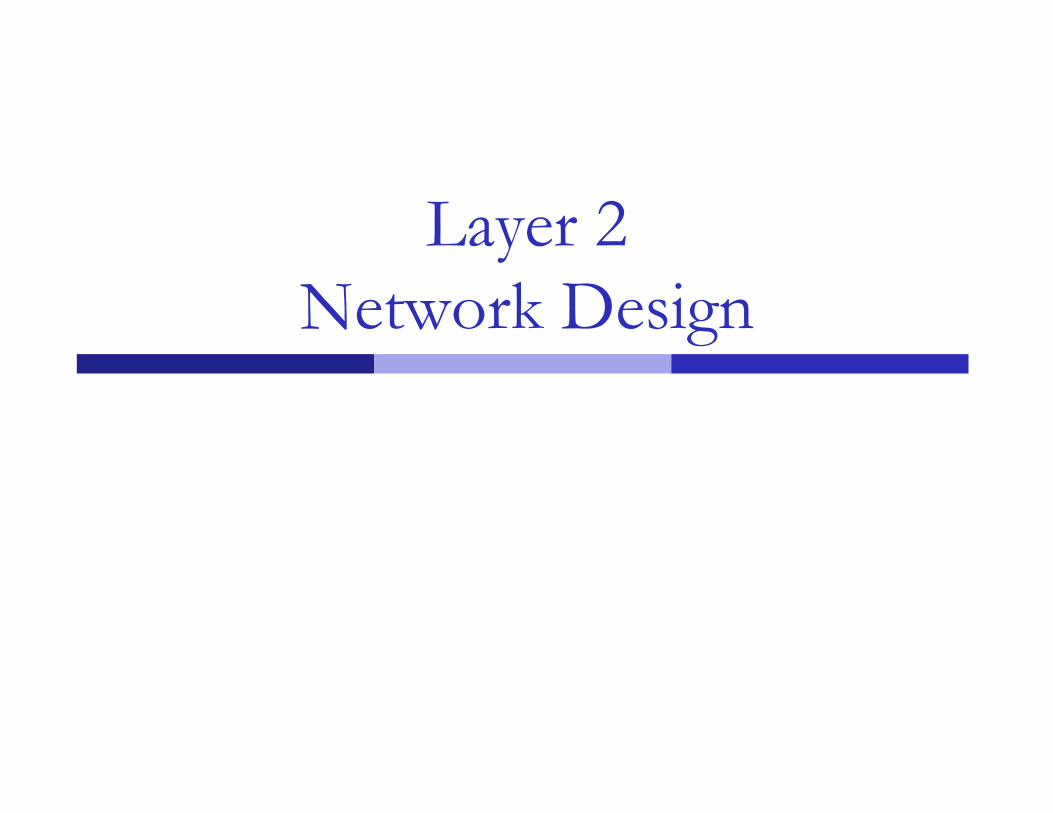
Layer-2 Network Design
A good network design is modular and hierarchical, with a clear separation of functions: Core: Resilient, few changes, few features, high
bandwidth, CPU power Distribution: Aggregation, redundancy Access: Port density, affordability, security
features, many adds, moves and changes
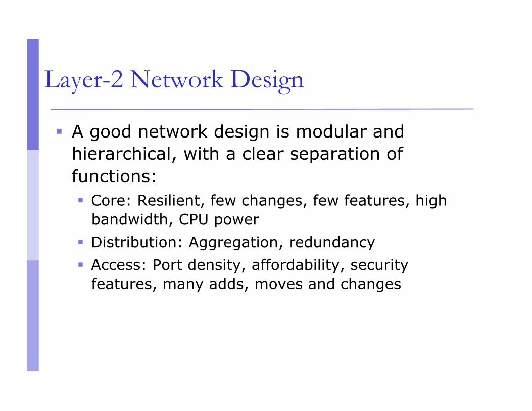
Layer-2 Network Design - Simple ISP1
Access
Core
Network Border
Distribution
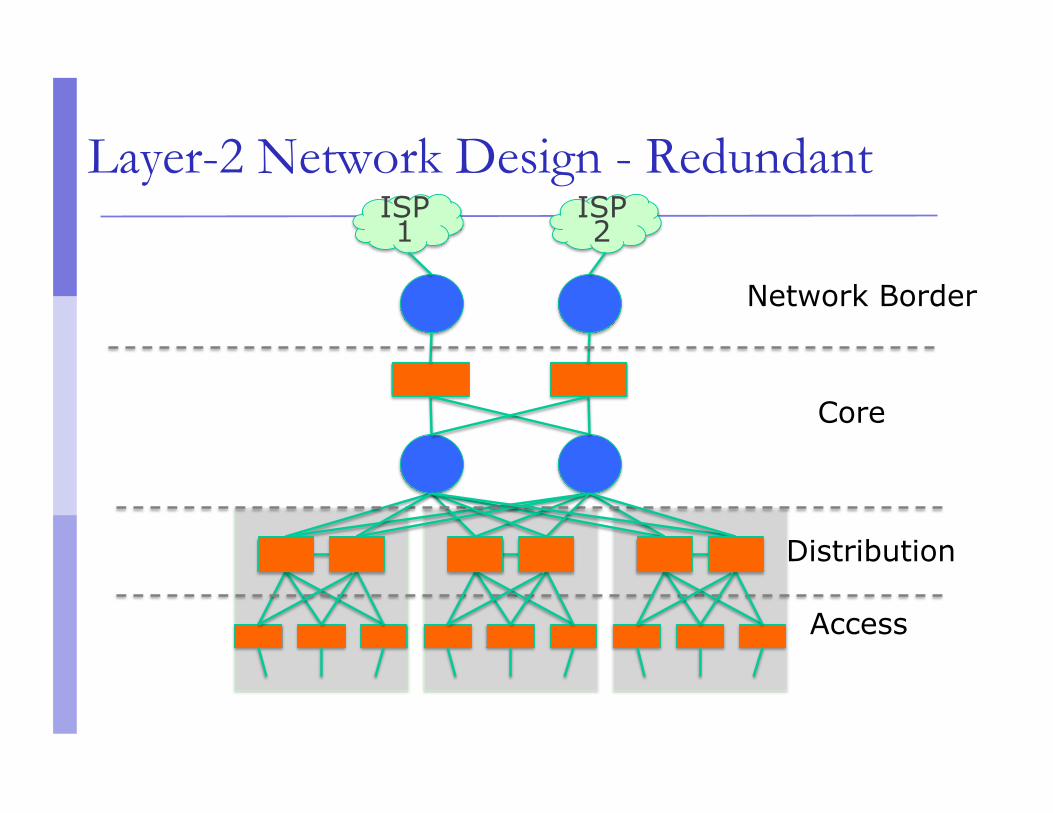
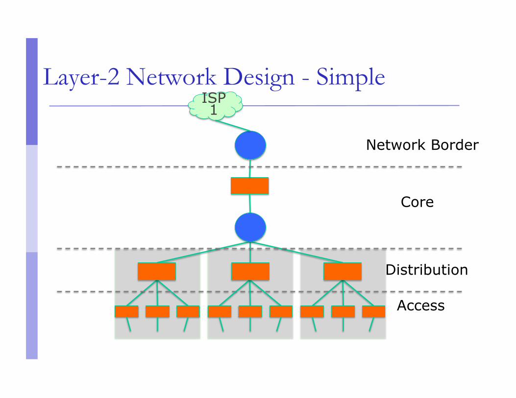
Layer-2 Network Design - Redundant ISP1
ISP2
Access
Core
Network Border
Distribution
In-Building and Layer 2
There is usually a correspondence between building separation and subnet separation Switching inside a building Routing between buildings
This will depend on the size of the network Very small networks can get by with doing
switching between buildings Very large networks might need to do routing
inside buildings
Layer 2 Concepts
Layer 2 protocols basically control access to a shared medium (copper, fiber, electro-magnetic waves)
Ethernet is the de-facto wired-standard today Reasons:
Simple Cheap Manufacturers keep making it faster
Wireless (802.11a,b,g,n) is also Layer-2 technology.
Ethernet Functions
Source and Destination identification MAC addresses
Detect and avoid frame collisions Listen and wait for channel to be available If collision occurs, wait a random period before
retrying This is called CASMA-CD: Carrier Sense Multiple Access
with Collision Detection

Ethernet Frame
SFD = Start of Frame Delimiter DA = Destination Address SA = Source Address CRC = Cyclick Redundancy Check
Evolution of Ethernet Topologies
Bus Everybody on the same coaxial cable
Star One central device connects every other node
First with hubs (repeated traffic) Later with switches (bridged traffic)
Structured cabling for star topologies standardized
Switched Star Topology Benefits
It’s modular: Independent wires for each end node Independent traffic in each wire A second layer of switches can be added to build a
hierarchical network that extends the same two benefits above
ALWAYS DESIGN WITH MODULARITY IN MIND
Hub
Receives a frame on one port and sends it out every other port, always.
Collision domain is not reduced Traffic ends up in places where it’s not needed
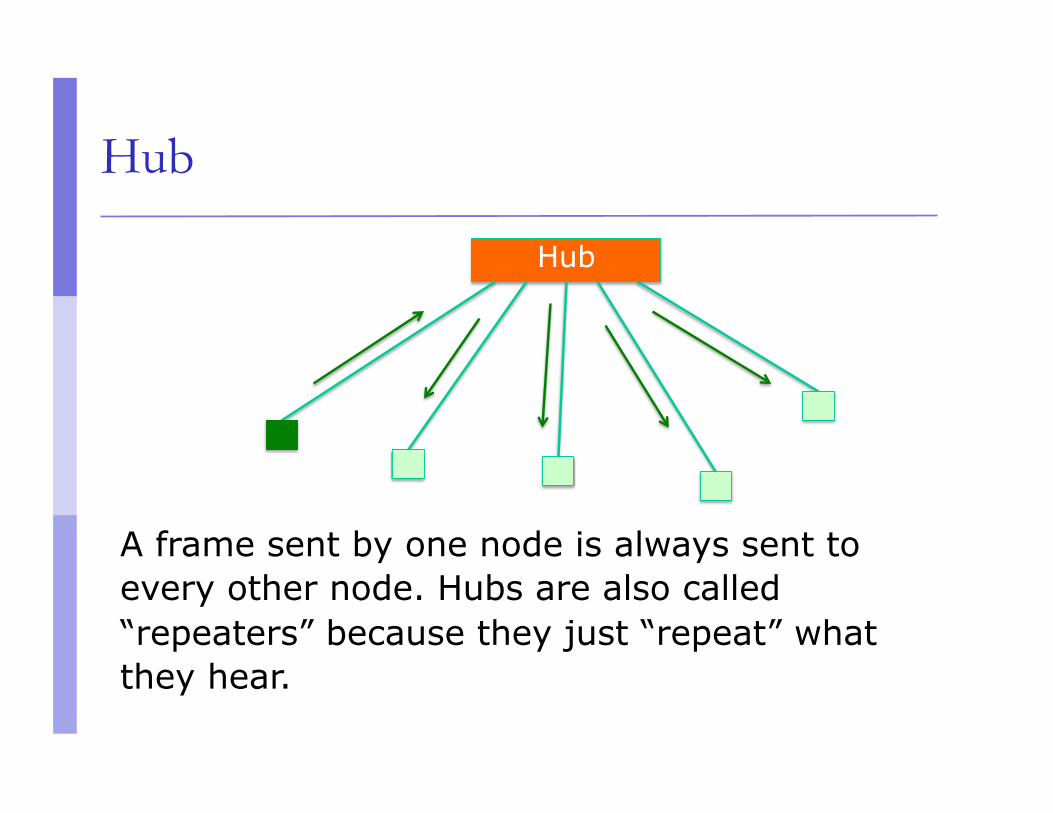
Hub
Hub
A frame sent by one node is always sent to every other node. Hubs are also called “repeaters” because they just “repeat” what they hear.
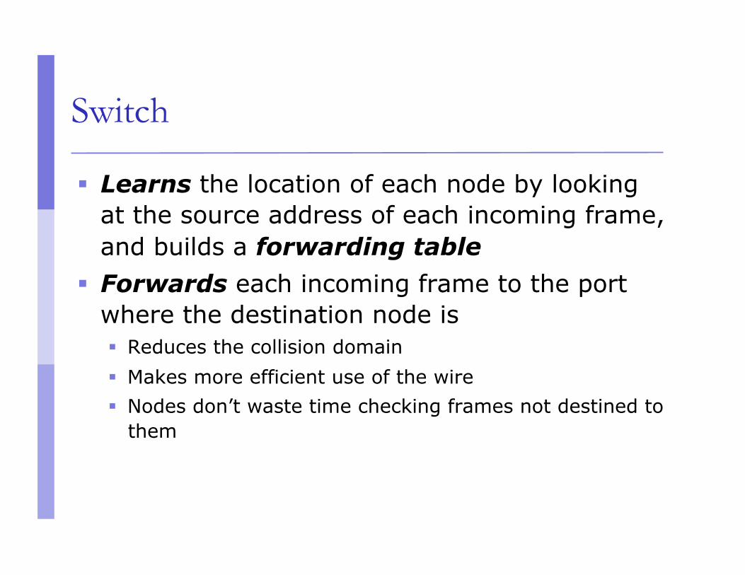
Switch
Learns the location of each node by looking at the source address of each incoming frame, and builds a forwarding table
Forwards each incoming frame to the port where the destination node is Reduces the collision domain Makes more efficient use of the wire Nodes don’t waste time checking frames not destined to
them
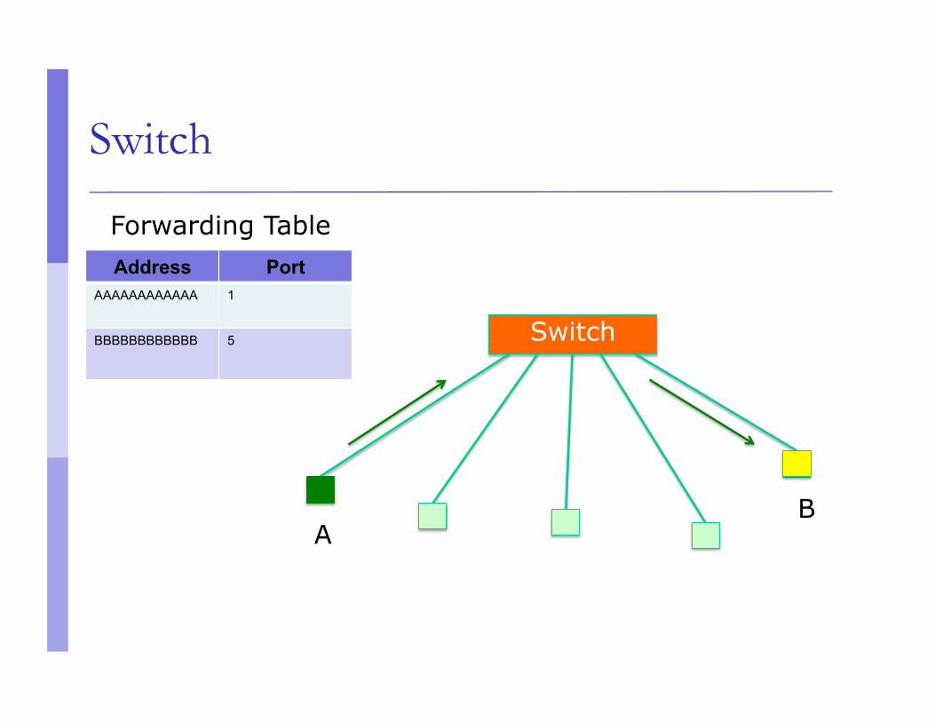
Switch
Switch
Address Port AAAAAAAAAAAA 1
BBBBBBBBBBBB 5
A B
Forwarding Table
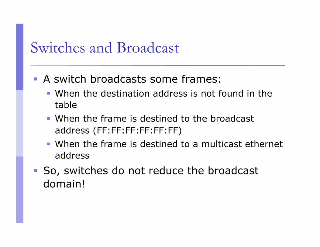
Switches and Broadcast
A switch broadcasts some frames: When the destination address is not found in the
table When the frame is destined to the broadcast
address (FF:FF:FF:FF:FF:FF) When the frame is destined to a multicast ethernet
address
So, switches do not reduce the broadcast domain!
Switch vs. Router
Routers more or less do with IP packets what switches do with Ethernet frames A router looks at the IP packet destination and
checks its routing table to decide where to forward the packet
Some differences: IP packets travel inside ethernet frames IP networks can be logically segmented into
subnets Switches do not usually know about IP, they only
deal with Ethernet frames
Switch vs. Router
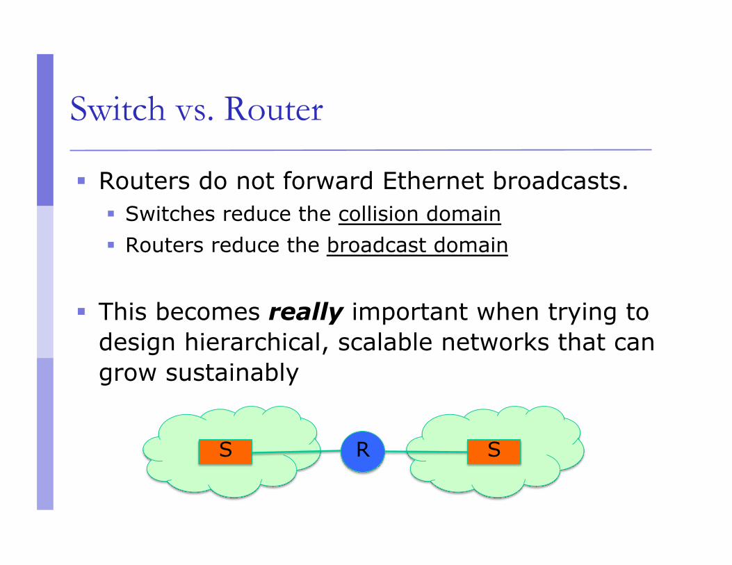
Routers do not forward Ethernet broadcasts. Switches reduce the collision domain Routers reduce the broadcast domain
This becomes really important when trying to design hierarchical, scalable networks that can grow sustainably
S R S
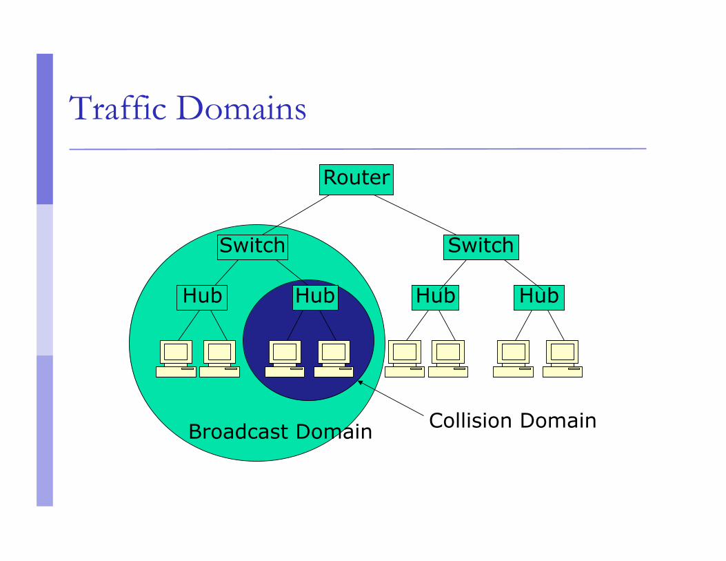
Traffic Domains
Router
Hub Hub
Switch Switch
Hub Hub
Broadcast Domain Collision Domain
Traffic Domains
Try to eliminate collision domains Get rid of hubs! Actually hubs are very rare today.
Try to keep your broadcast domain limited to no more than 250 simultaneously connected hosts Segment your network using routers
Layer 2 Network Design Guidelines
Always connect hierarchically If there are multiple switches in a building, use an
aggregation switch Locate the aggregation switch close to the building
entry point (e.g. fiber panel) Locate edge switches close to users (e.g. one per
floor) Max length for Cat 5 is 100 meters
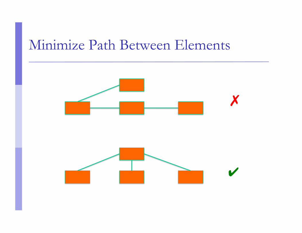
Minimize Path Between Elements
✔
✗
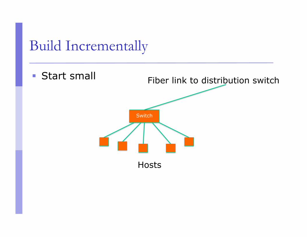
Build Incrementally
Start small
Switch
Fiber link to distribution switch
Hosts
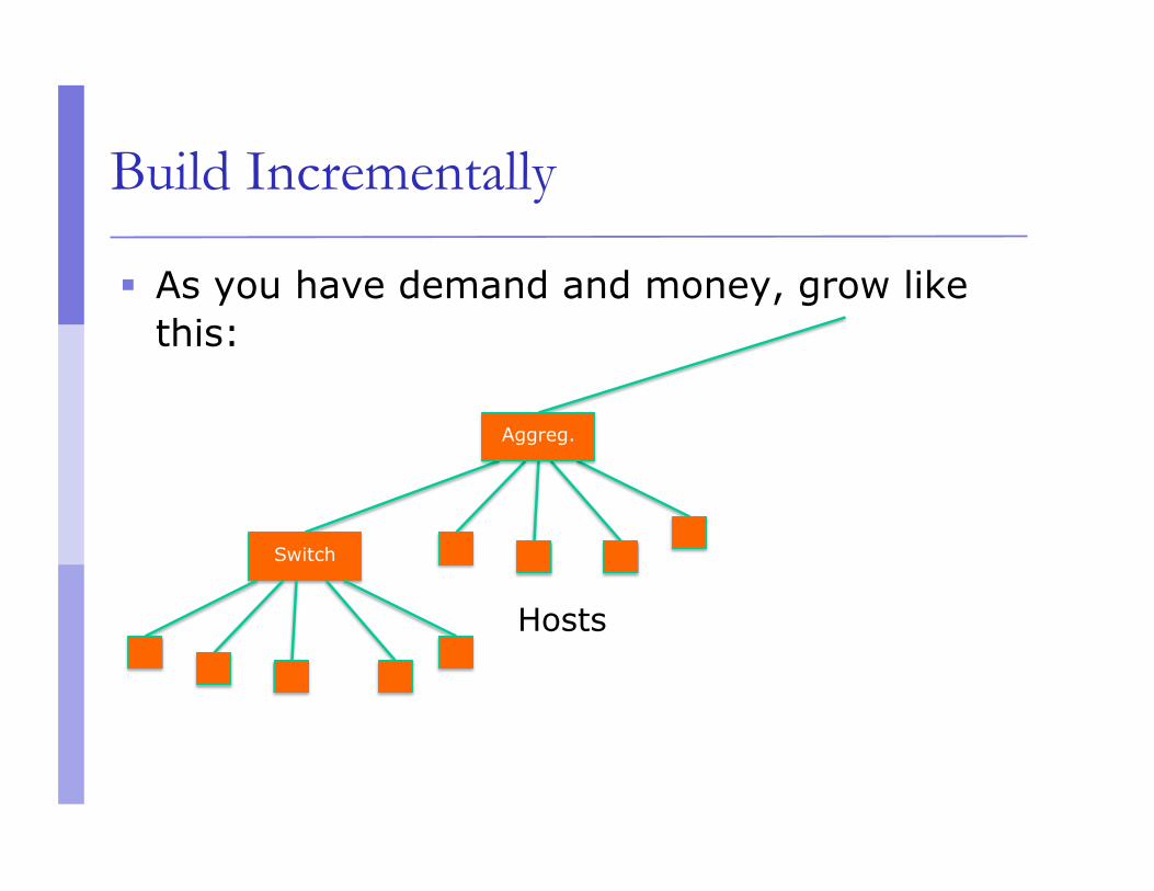
Build Incrementally
As you have demand and money, grow like this:
Switch
Aggreg.
Hosts
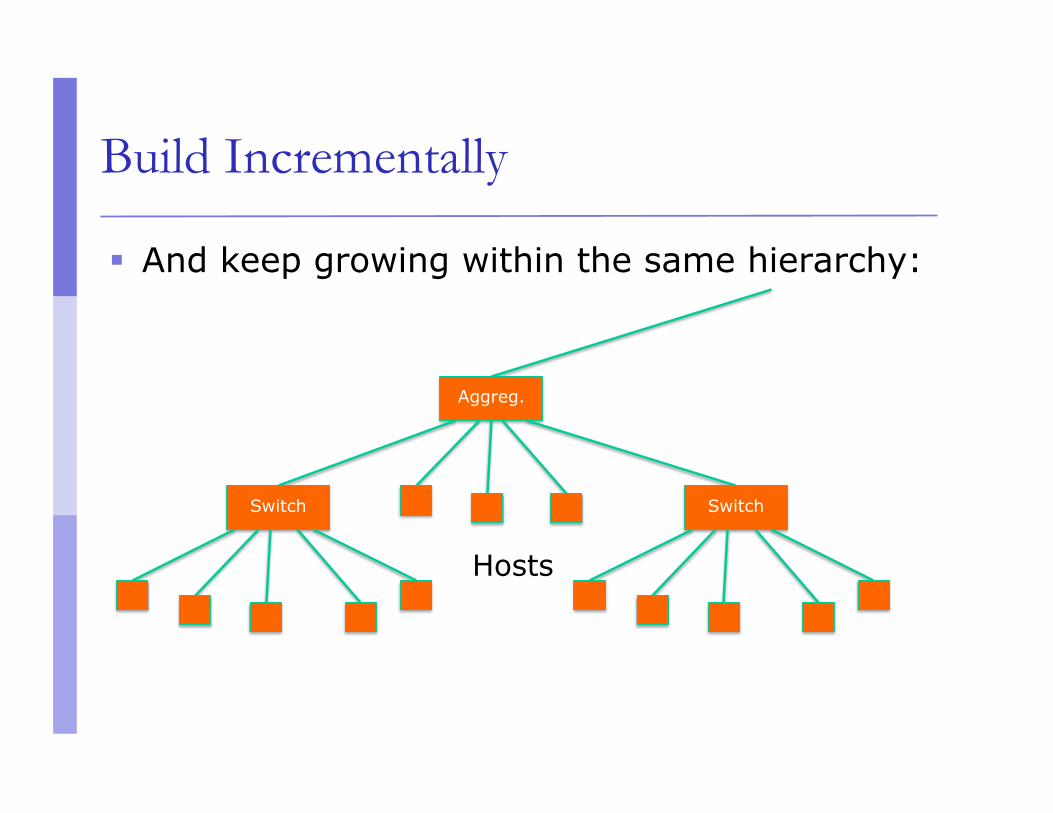
Build Incrementally
And keep growing within the same hierarchy:
Aggreg.
Hosts
Switch Switch
Hosts
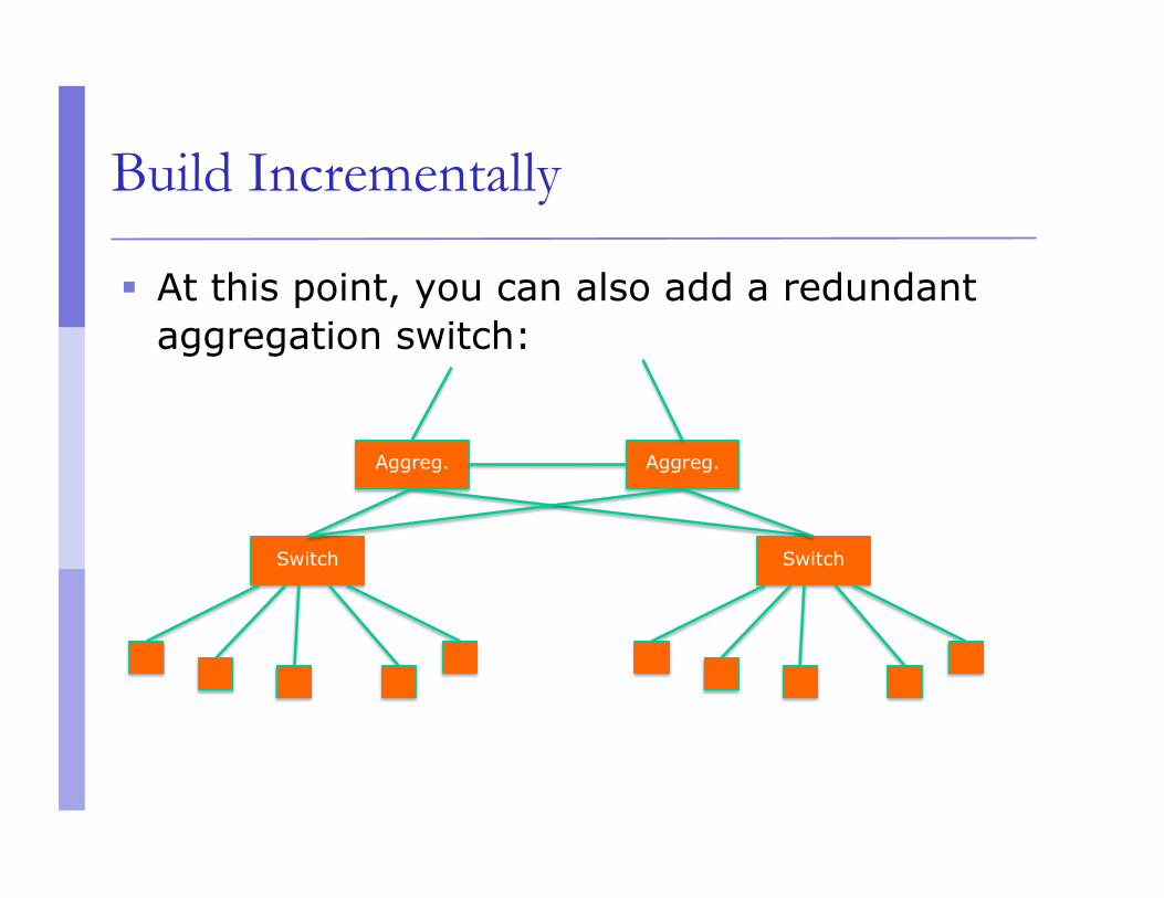
Build Incrementally
At this point, you can also add a redundant aggregation switch:
Aggreg.
Hosts
Switch Switch
Aggreg.
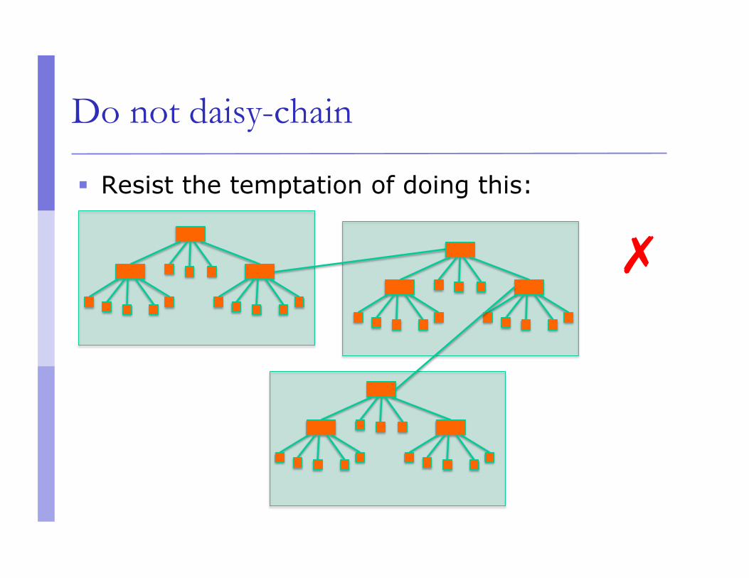
Do not daisy-chain
Resist the temptation of doing this:
✗
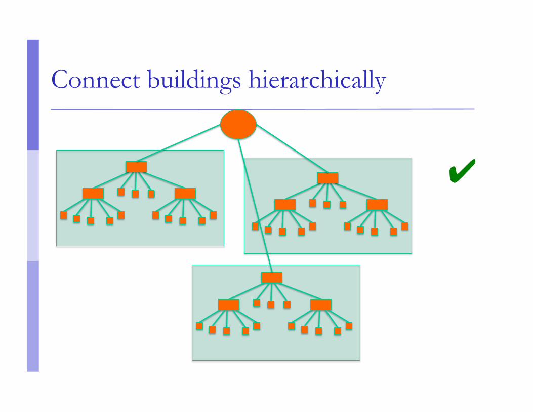
Connect buildings hierarchically
✔
Virtual LANs (VLANs)
Allow us to split switches into separate (virtual) switches
Only members of a VLAN can see that VLAN’s traffic Inter-vlan traffic must go through a router
VLAN introduction
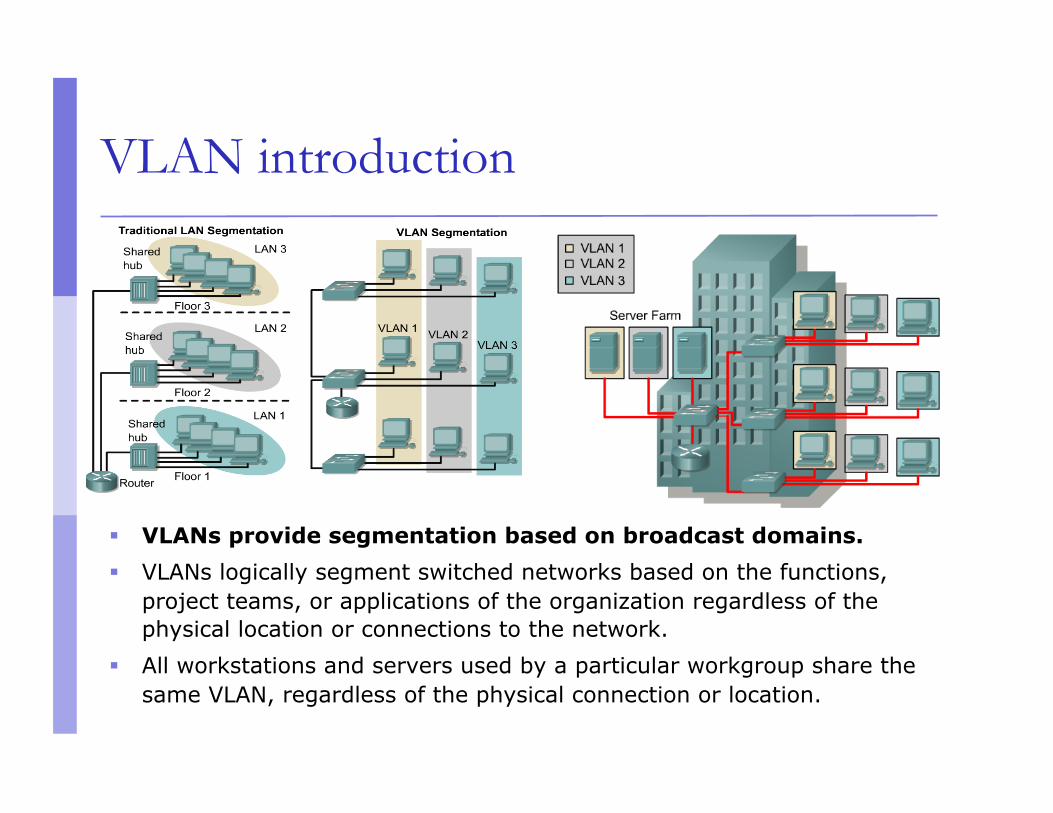
VLANs provide segmentation based on broadcast domains.
VLANs logically segment switched networks based on the functions, project teams, or applications of the organization regardless of the physical location or connections to the network.
All workstations and servers used by a particular workgroup share the same VLAN, regardless of the physical connection or location.
Local VLANs
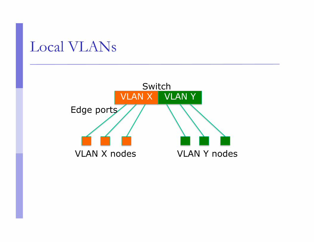
2 VLANs or more within a single switch
VLANs address scalability, security, and network management. Routers in VLAN topologies provide broadcast filtering, security, and traffic flow management.
Edge ports, where end nodes are connected, are configured as members of a VLAN
The switch behaves as several virtual switches, sending traffic only within VLAN members.
Switches may not bridge any traffic between VLANs, as this would violate the integrity of the VLAN broadcast domain.
Traffic should only be routed between VLANs.
Local VLANs
VLAN X VLAN Y Switch
VLAN X nodes VLAN Y nodes
Edge ports
Broadcast domains with VLANs and routers
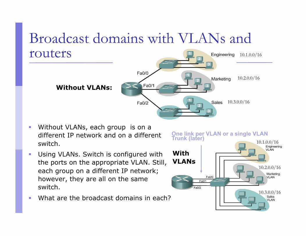
Without VLANs, each group is on a different IP network and on a different switch.
Using VLANs. Switch is configured with the ports on the appropriate VLAN. Still, each group on a different IP network; however, they are all on the same switch.
What are the broadcast domains in each?
Without VLANs:
One link per VLAN or a single VLAN Trunk (later)
With VLANs
10.1.0.0/16
10.2.0.0/16
10.3.0.0/16
10.1.0.0/16
10.2.0.0/16
10.3.0.0/16
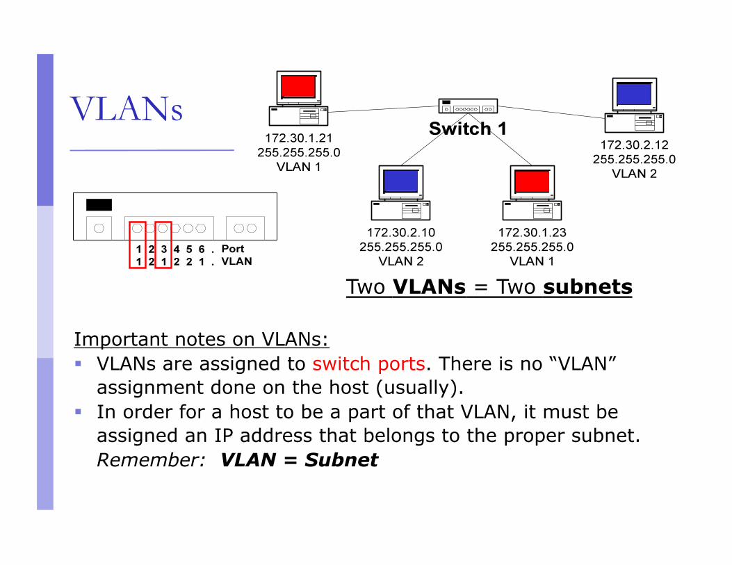
VLANs
Two VLANs = Two subnets
Important notes on VLANs: VLANs are assigned to switch ports. There is no “VLAN”
assignment done on the host (usually). In order for a host to be a part of that VLAN, it must be
assigned an IP address that belongs to the proper subnet. Remember: VLAN = Subnet
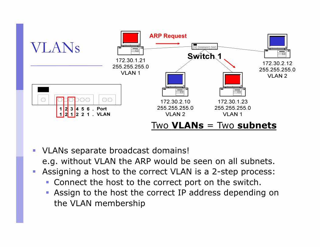
VLANs
Two VLANs = Two subnets
VLANs separate broadcast domains! e.g. without VLAN the ARP would be seen on all subnets.
Assigning a host to the correct VLAN is a 2-step process: Connect the host to the correct port on the switch. Assign to the host the correct IP address depending on
the VLAN membership
ARP Request
VLAN operation
As a device enters the network, it automatically assumes the VLAN membership of the port to which it is attached.
The default VLAN for every port in the switch is VLAN 1 and cannot be deleted. (This statement does not give the whole story. More in the lab later for interested groups…)
All other ports on the switch may be reassigned to alternate VLANs.
VLANs across switches
Two switches can exchange traffic from one or more VLANs
Inter-switch links are configured as trunks, carrying frames from all or a subset of a switch’s VLANs
Each frame carries a tag that identifies which VLAN it belongs to
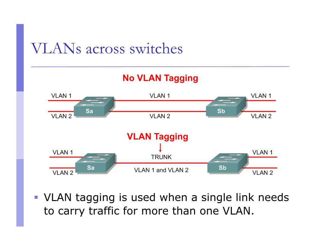
VLANs across switches
VLAN tagging is used when a single link needs to carry traffic for more than one VLAN.
No VLAN Tagging
VLAN Tagging
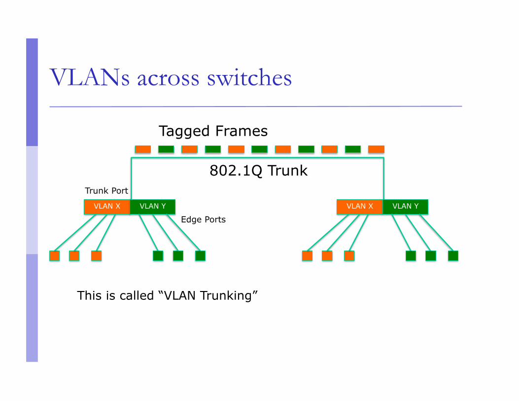
VLANs across switches
802.1Q Trunk
Tagged Frames
VLAN X VLAN Y VLAN X VLAN Y
Edge Ports
Trunk Port
This is called “VLAN Trunking”
802.1Q
The IEEE standard that defines how ethernet frames should be tagged when moving across switch trunks
This means that switches from different vendors are able to exchange VLAN traffic.
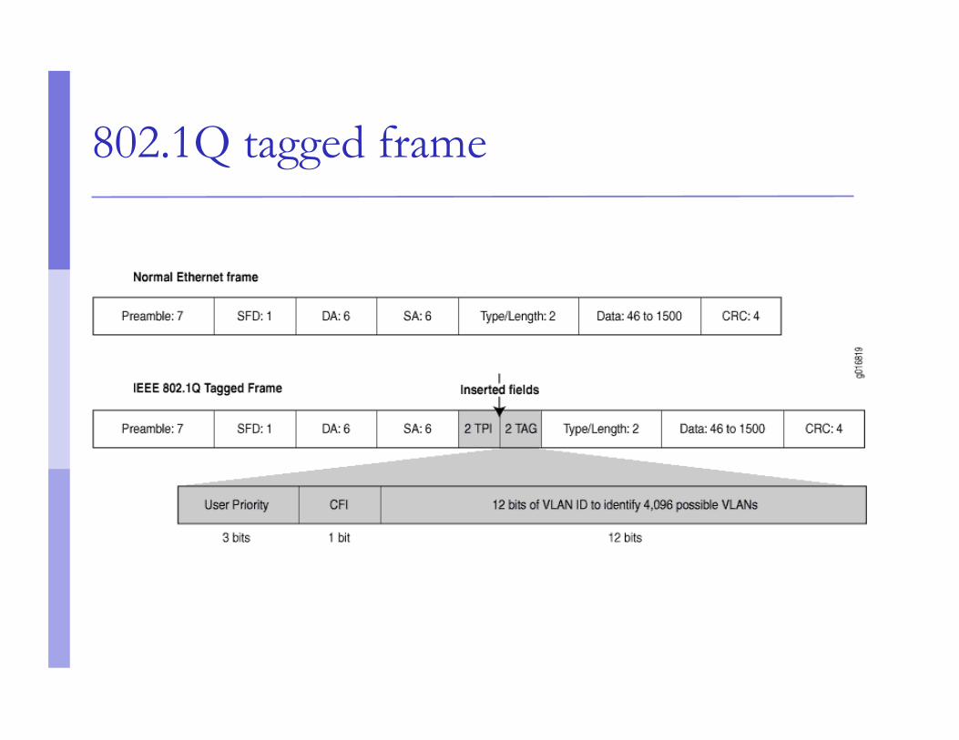
802.1Q tagged frame
Tagged vs. Untagged
Edge ports are not tagged, they are just “members” of a VLAN
You only need to tag frames in switch-to-switch links (trunks), when transporting multiple VLANs
A trunk can transport both tagged and untagged VLANs As long as the two switches agree on how to handle
those
VLANS increase complexity
You can no longer “just replace” a switch Now you have VLAN configuration to maintain Field technicians need more skills
You have to make sure that all the switch-to-switch trunks are carrying all the necessary VLANs Need to keep in mind when adding/removing
VLANs
Good reasons to use VLANs
You want to segment your network into multiple subnets, but can’t buy enough switches Hide sensitive infrastructure like IP phones,
building controls, etc.
Separate control traffic from user traffic Restrict who can access your switch management
address
Bad reasons to use VLANs
Because you can, and you feel cool Because they will completely secure your
hosts (or so you think) Because they allow you to extend the same IP
network over multiple separate buildings
Do not build “VLAN spaghetti”
Extending a VLAN to multiple buildings across trunk ports
Bad idea because: Broadcast traffic is carried across all trunks from
one end of the network to another Broadcast storm can spread across the extent of
the VLAN Maintenance and troubleshooting nightmare
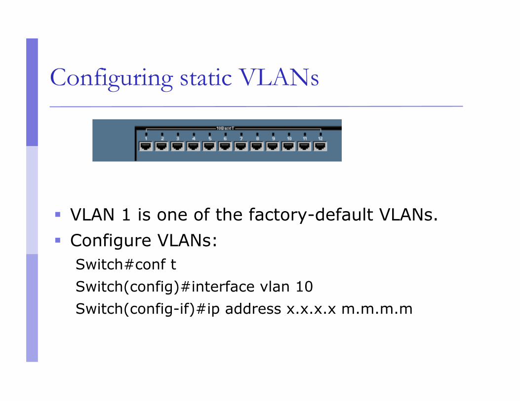
Configuring static VLANs
VLAN 1 is one of the factory-default VLANs. Configure VLANs:
Switch#conf t Switch(config)#interface vlan 10 Switch(config-if)#ip address x.x.x.x m.m.m.m
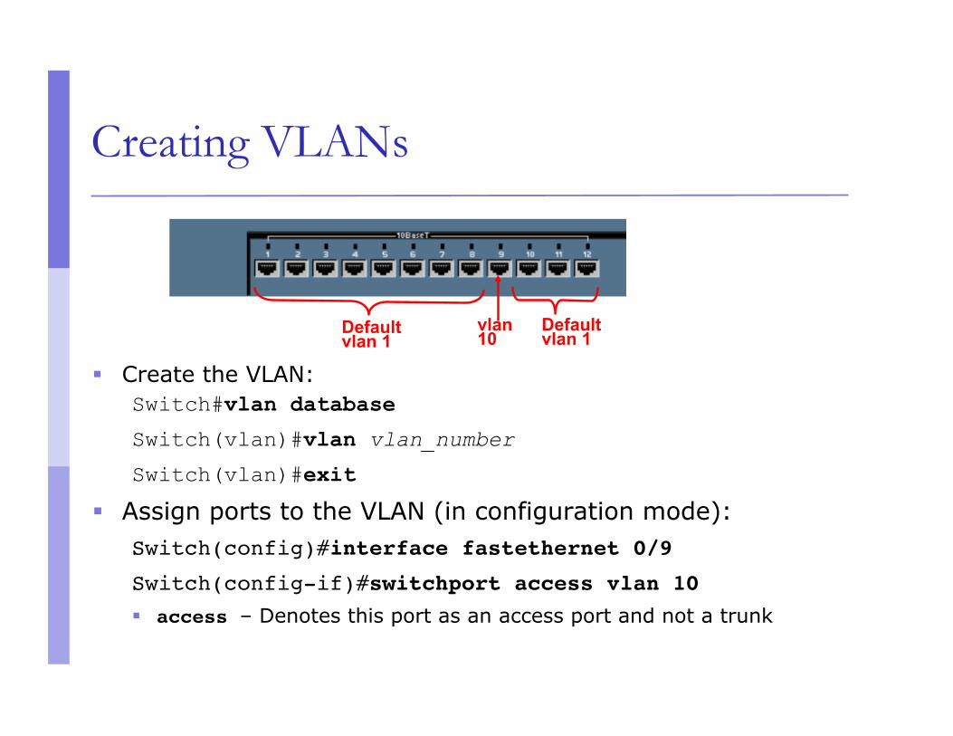
Creating VLANs
Create the VLAN: Switch#vlan database Switch(vlan)#vlan vlan_number
Switch(vlan)#exit Assign ports to the VLAN (in configuration mode):
Switch(config)#interface fastethernet 0/9
Switch(config-if)#switchport access vlan 10
access – Denotes this port as an access port and not a trunk
vlan 10 Default
vlan 1 Default vlan 1
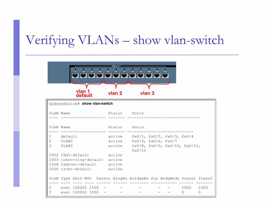
Verifying VLANs – show vlan-switch
vlan 3 vlan 2 vlan 1 default
show vlan-switch
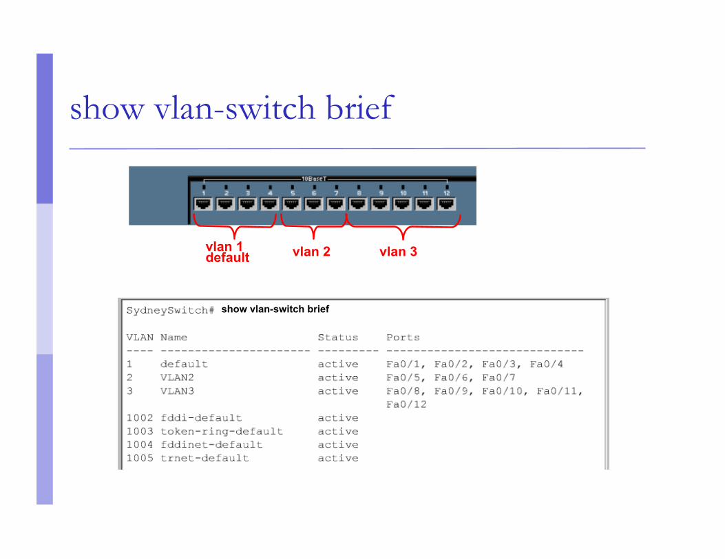
show vlan-switch brief
vlan 3 vlan 2 vlan 1 default
show vlan-switch brief
vlan database commands
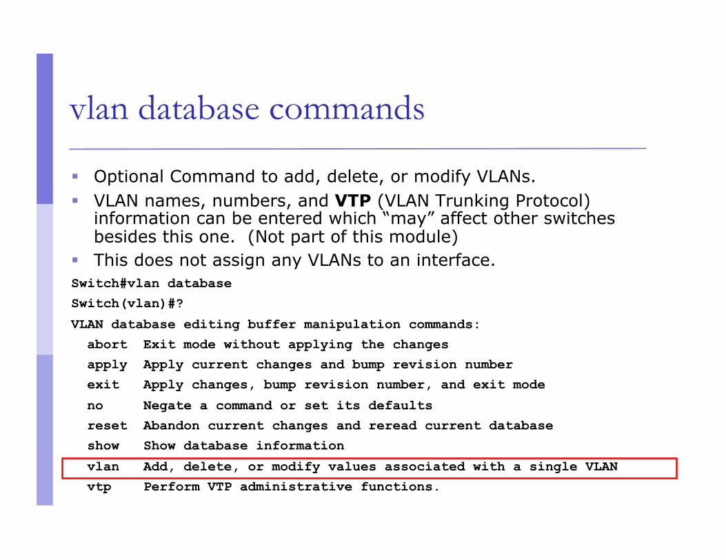
Optional Command to add, delete, or modify VLANs. VLAN names, numbers, and VTP (VLAN Trunking Protocol)
information can be entered which “may” affect other switches besides this one. (Not part of this module)
This does not assign any VLANs to an interface. Switch#vlan database Switch(vlan)#?
VLAN database editing buffer manipulation commands: abort Exit mode without applying the changes
apply Apply current changes and bump revision number
exit Apply changes, bump revision number, and exit mode
no Negate a command or set its defaults reset Abandon current changes and reread current database
show Show database information
vlan Add, delete, or modify values associated with a single VLAN vtp Perform VTP administrative functions.
VLAN trunking
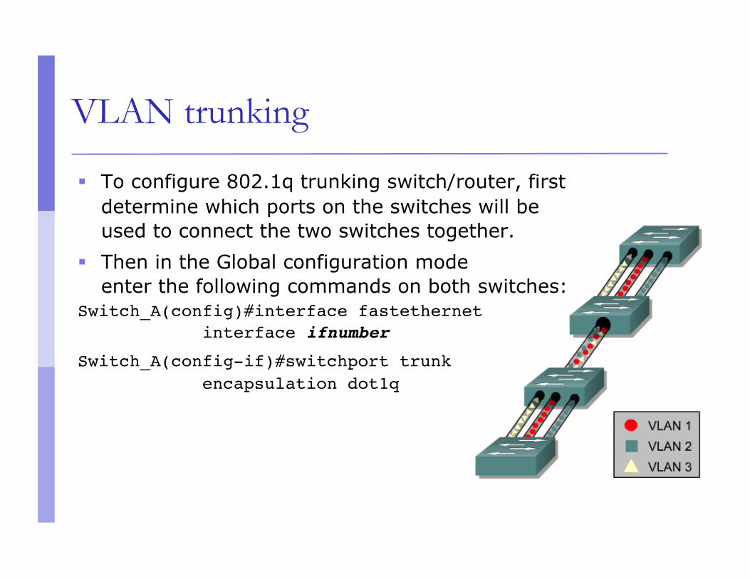
To configure 802.1q trunking switch/router, first determine which ports on the switches will be used to connect the two switches together.
Then in the Global configuration mode enter the following commands on both switches:
Switch_A(config)#interface fastethernet interface ifnumber
Switch_A(config-if)#switchport trunk encapsulation dot1q
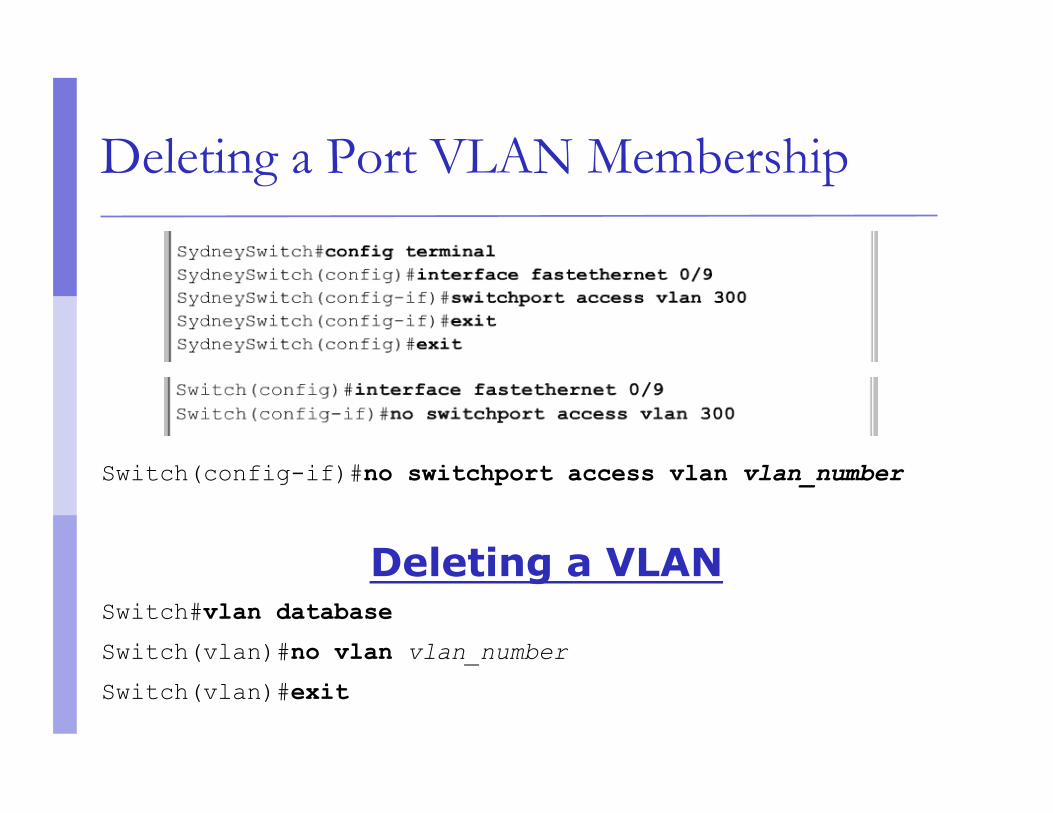
Deleting a Port VLAN Membership
Switch(config-if)#no switchport access vlan vlan_number
Deleting a VLAN Switch#vlan database
Switch(vlan)#no vlan vlan_number
Switch(vlan)#exit
Link Aggregation
Link Aggregation
Also known as port bundling, link bundling You can use multiple links in parallel as a
single, logical link For increased capacity For redundancy (fault tolerance)
LACP (Link Aggregation Control Protocol) is a standardized method of negotiating these bundled links between switches
LACP Operation
Two switches connected via multiple links will send LACPDU packets, identifying themselves and the port capabilities
They will then automatically build the logical aggregated links, and then pass traffic.
Switch ports can be configured as active or passive
LACP Operation
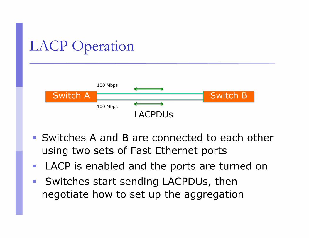
Switches A and B are connected to each other using two sets of Fast Ethernet ports
LACP is enabled and the ports are turned on Switches start sending LACPDUs, then
negotiate how to set up the aggregation
Switch A Switch B
LACPDUs
100 Mbps
100 Mbps
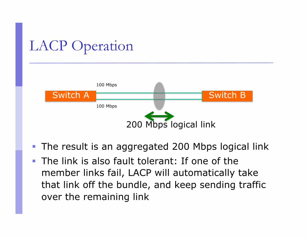
LACP Operation
The result is an aggregated 200 Mbps logical link The link is also fault tolerant: If one of the
member links fail, LACP will automatically take that link off the bundle, and keep sending traffic over the remaining link
200 Mbps logical link
Switch A Switch B 100 Mbps
100 Mbps
Distributing Traffic in Bundled Links
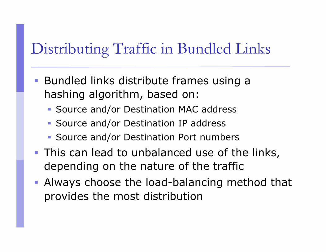
Bundled links distribute frames using a hashing algorithm, based on: Source and/or Destination MAC address Source and/or Destination IP address Source and/or Destination Port numbers
This can lead to unbalanced use of the links, depending on the nature of the traffic
Always choose the load-balancing method that provides the most distribution
Switching Loops
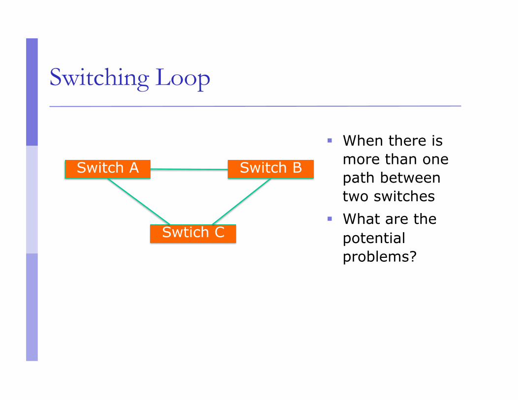
Switching Loop
When there is more than one path between two switches
What are the potential problems?
Switch A Switch B
Swtich C
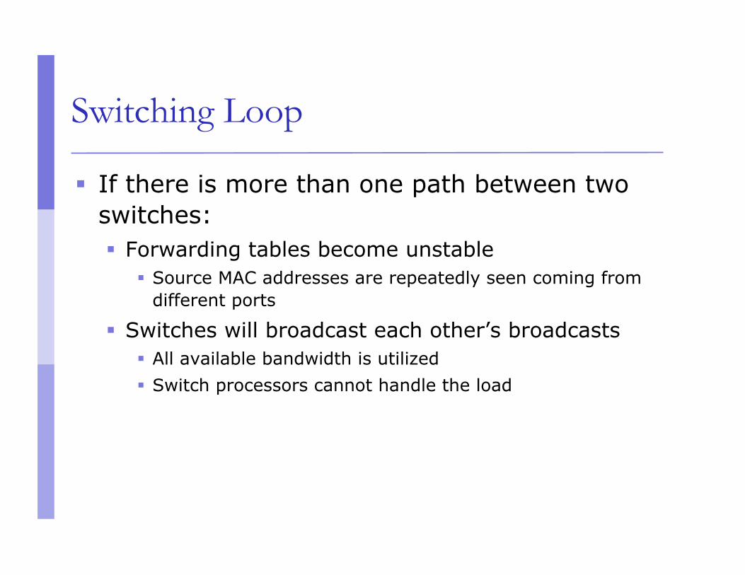
Switching Loop
If there is more than one path between two switches: Forwarding tables become unstable
Source MAC addresses are repeatedly seen coming from different ports
Switches will broadcast each other’s broadcasts All available bandwidth is utilized Switch processors cannot handle the load
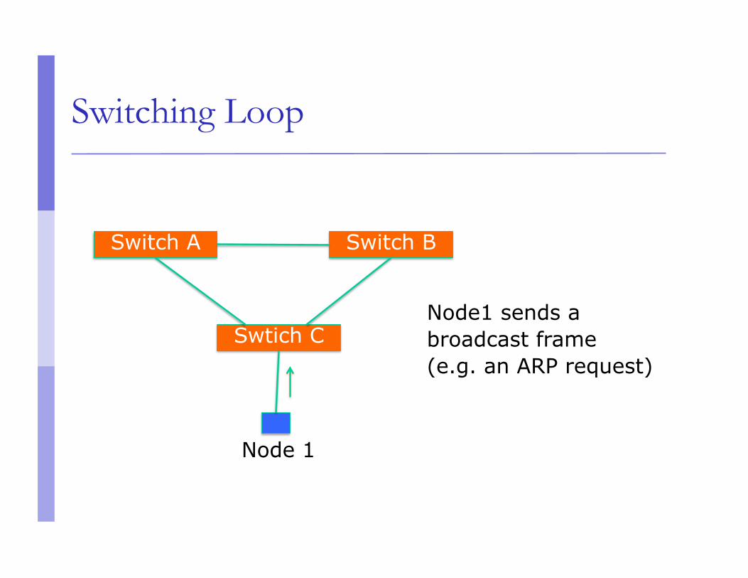
Switching Loop
Switch A Switch B
Swtich C Node1 sends a broadcast frame (e.g. an ARP request)
Node 1
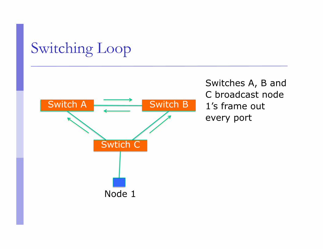
Switching Loop
Switch A Switch B
Swtich C
Switches A, B and C broadcast node 1’s frame out every port
Node 1
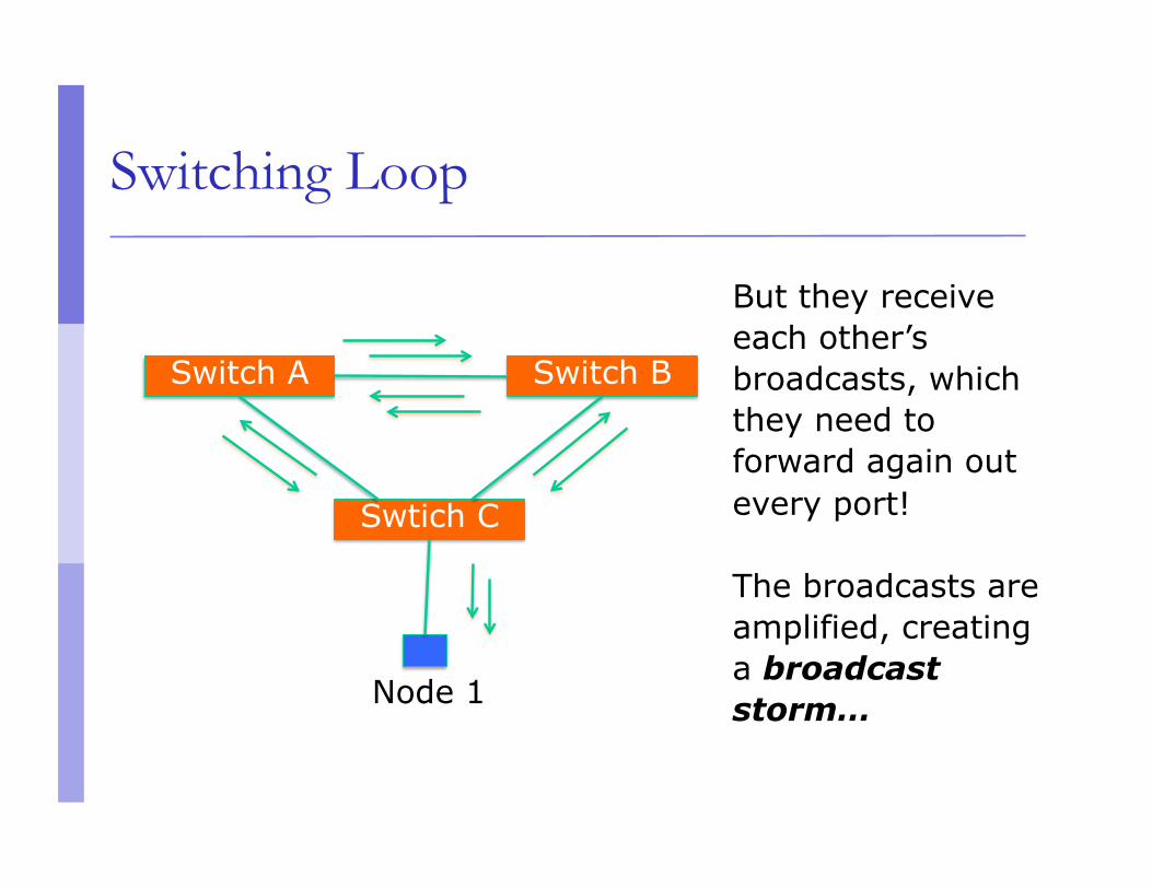
Switching Loop
Switch A Switch B
Swtich C
But they receive each other’s broadcasts, which they need to forward again out every port!
The broadcasts are amplified, creating a broadcast storm… Node 1
Good Switching Loops???
But you can take advantage of loops! Redundant paths improve resilience when:
A switch fails Wiring breaks
How to achieve redundancy without creating dangerous traffic loops?
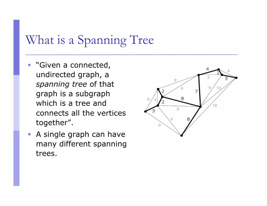
What is a Spanning Tree
“Given a connected, undirected graph, a spanning tree of that graph is a subgraph which is a tree and connects all the vertices together”.
A single graph can have many different spanning trees.
Spanning Tree Protocol
The purpose of the protocol is to have bridges dynamically discover a subset of the topology that is loop-free (a tree) and yet has just enough connectivity so that where physically possible, there is a path between every switch
Spanning Tree Protocol
Several flavors: Traditional Spanning Tree (802.1d) Rapid Spanning Tree or RSTP (802.1w) Multiple Spanning Tree or MSTP (802.1s)
Traditional Spanning Tree (802.1d)
Switches exchange messages that allow them to compute the Spanning Tree These messages are called BPDUs (Bridge Protocol
Data Units) Two types of BPDUs:
Configuration Topology Change Notification (TCN)
Traditional Spanning Tree (802.1d)
First Step: Decide on a point of reference: the Root Bridge The election process is based on the Bridge ID,
which is composed of: The Bridge Priority: A two-byte value that is configurable The MAC address: A unique, hardcoded address that
cannot be changed.
Root Bridge Selection (802.1d)
Each switch starts by sending out BPDUs with a Root Bridge ID equal to its own Bridge ID I am the root!
Received BPDUs are analyzed to see if a lower Root Bridge ID is being announced If so, each switch replaces the value of the
advertised Root Bridge ID with this new lower ID
Eventually, they all agree on who the Root Bridge is
Root Bridge Selection (802.1d)
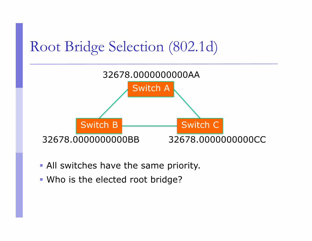
All switches have the same priority. Who is the elected root bridge?
Switch B Switch C
Switch A 32678.0000000000AA
32678.0000000000BB 32678.0000000000CC
Root Port Selection (802.1d)
Now each switch needs to figure out where it is in relation to the Root Bridge Each switch needs to determine its Root Port The key is to find the port with the lowest Root
Path Cost The cumulative cost of all the links leading to the Root
Bridge
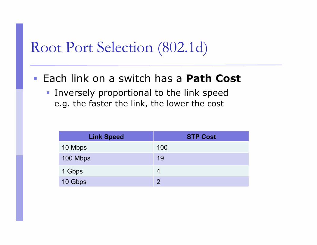
Root Port Selection (802.1d)
Each link on a switch has a Path Cost Inversely proportional to the link speed
e.g. the faster the link, the lower the cost
Link Speed STP Cost 10 Mbps 100 100 Mbps 19
1 Gbps 4 10 Gbps 2
Root Port Selection (802.1d)
Root Path Cost is the accumulation of a link’s Path Cost and the Path Costs learned from neighboring Switches. It answers the question: How much does it cost to
reach the Root Bridge through this port?
Root Port Selection (802.1d)
1. Root Bridge sends out BPDUs with a Root Path Cost value of 0
2. Neighbor receives BPDU and adds port’s Path Cost to Root Path Cost received
3. Neighbor sends out BPDUs with new cumulative value as Root Path Cost
4. Other neighbor’s down the line keep adding in the same fashion
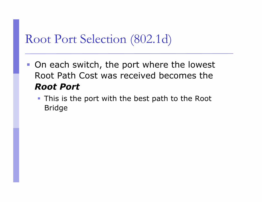
Root Port Selection (802.1d)
On each switch, the port where the lowest Root Path Cost was received becomes the Root Port This is the port with the best path to the Root
Bridge
32678.0000000000BB 32678.0000000000CC
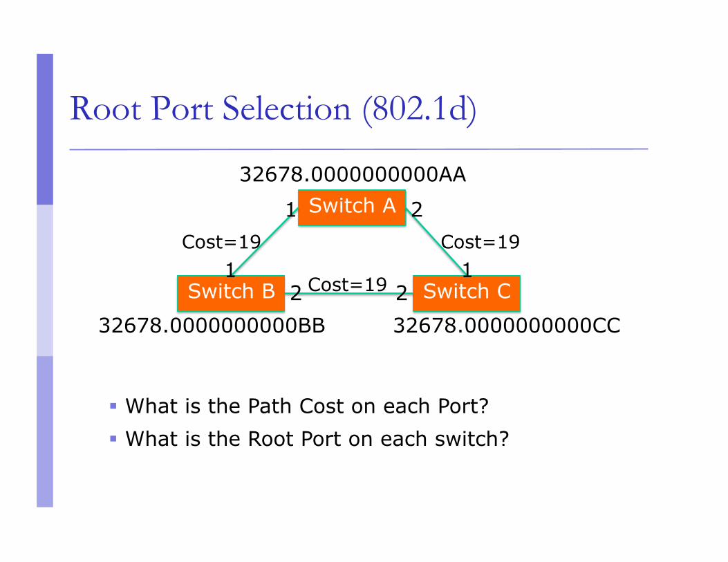
Root Port Selection (802.1d)
Cost=19 Cost=19
Cost=19
What is the Path Cost on each Port? What is the Root Port on each switch?
Switch B Switch C
Switch A 32678.0000000000AA
1 2
1 1 2 2
32678.0000000000BB 32678.0000000000CC
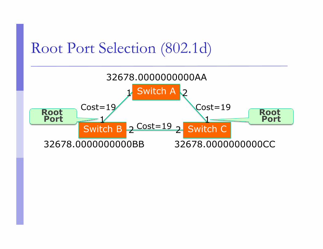
Root Port Selection (802.1d)
Cost=19 Cost=19
Cost=19 Switch B Switch C
Switch A 32678.0000000000AA
1 2
1 1 2 2
Root Port
Root Port
Electing Designated Ports (802.1d)
OK, we now have selected root ports but we haven’t solved the loop problem yet, have we?The links are still active!
Each network segment needs to have only one switch forwarding traffic to and from that segment
Switches then need to identify one Designated Port per link The one with the lowest cumulative Root Path Cost
to the Root Bridge
32678.0000000000BB 32678.0000000000CC
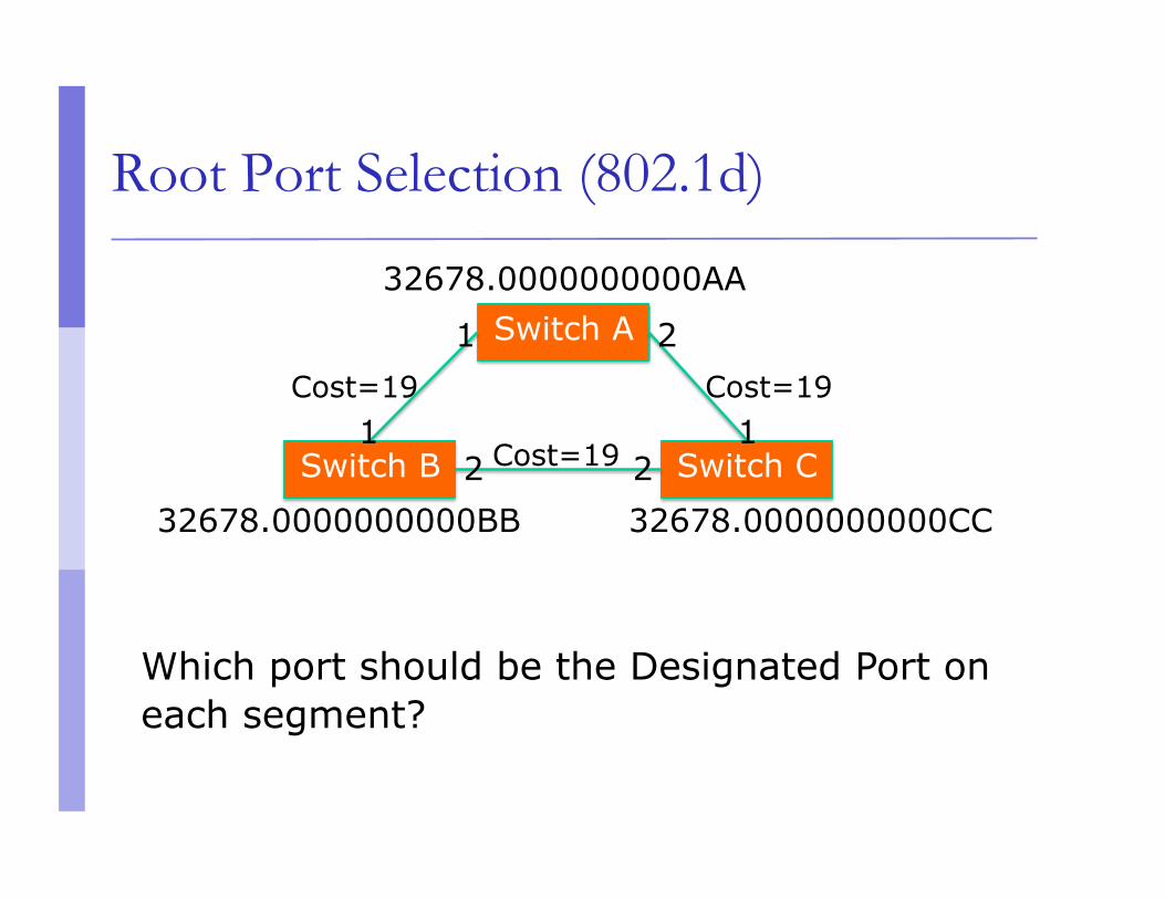
Root Port Selection (802.1d)
Cost=19 Cost=19
Cost=19 Switch B Switch C
Switch A 32678.0000000000AA
1 2
1 1 2 2
Which port should be the Designated Port on each segment?
Electing Designated Ports (802.1d)
Two or more ports in a segment having identical Root Path Costs is possible, which results in a tie condition
All STP decisions are based on the following sequence of conditions: Lowest Root Bridge ID Lowest Root Path Cost to Root Bridge Lowest Sender Bridge ID Lowest Sender Port ID
32678.0000000000BB 32678.0000000000CC
Root Port Selection (802.1d)
Cost=19 Cost=19
Cost=19 Switch B Switch C
Switch A 32678.0000000000AA
1 2
1 1 2 2
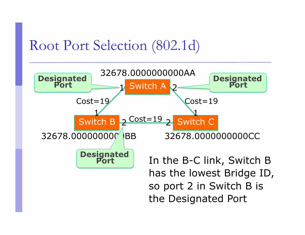
Designated Port
Designated Port
Designated Port In the B-C link, Switch B
has the lowest Bridge ID, so port 2 in Switch B is the Designated Port
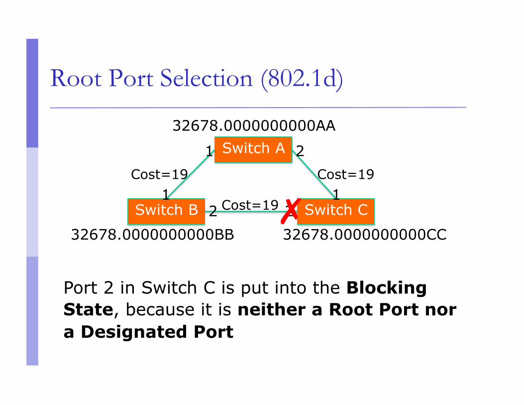
Blocking a port
Any port that is not elected as either a Root Port, nor a Designated Port is put into the Blocking State.
This step effectively breaks the loop and completes the Spanning Tree.
32678.0000000000BB 32678.0000000000CC
Root Port Selection (802.1d)
Cost=19 Cost=19
Cost=19 Switch B Switch C
Switch A 32678.0000000000AA
1 2
1 1 2 2
Port 2 in Switch C is put into the Blocking State, because it is neither a Root Port nor a Designated Port
✗
Spanning Tree Protocol States
Disabled Port is shut down
Blocking Not forwarding frames Receiving BPDUs
Listening Not forwarding frames Sending and receiving BPDUs
Spanning Tree Protocol States
Learning Not forwarding frames Sending and receiving BPDUs Learning new MAC addresses
Forwarding Forwarding frames Sending and receiving BPDUs Learning new MAC addresses
STP Topology Changes
Switches will recalculate if: A new switch is introduced
It could be the new Root Bridge!
A switch fails A link fails
Root Bridge Placement
Using default STP parameters might result in an undesired situation Traffic will flow in non-optimal ways An unstable or slow switch might become the root
You need to plan your assignment of bridge priorities carefully
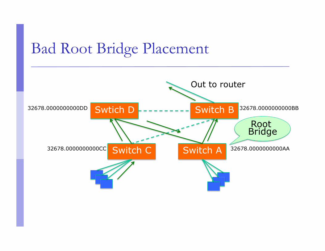
Bad Root Bridge Placement
Switch B
Switch C
Swtich D 32678.0000000000DD 32678.0000000000BB
32678.0000000000CC Switch A 32678.0000000000AA
Root Bridge
Out to router
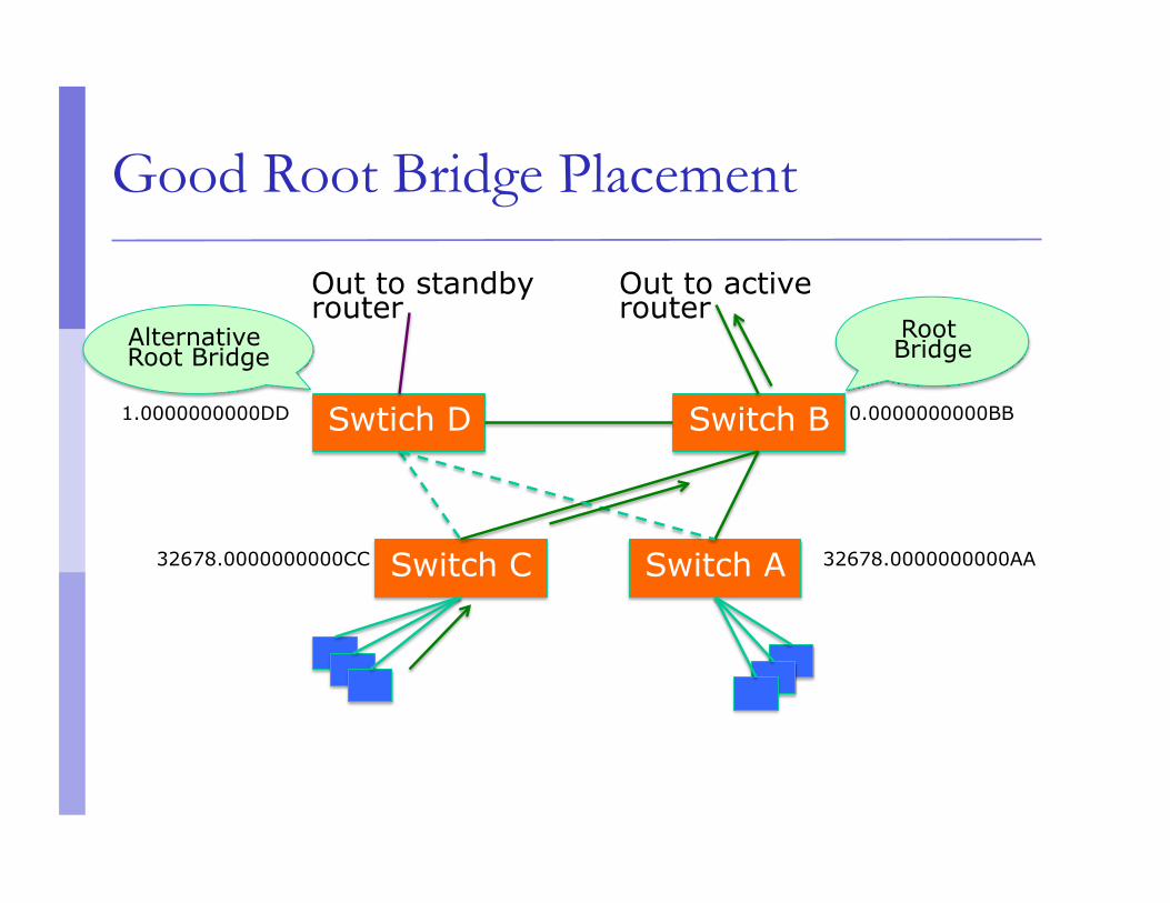
Good Root Bridge Placement
Switch B
Switch C
Swtich D 1.0000000000DD 0.0000000000BB
32678.0000000000CC Switch A 32678.0000000000AA
Alternative Root Bridge
Out to active router
Root Bridge
Out to standby router
Protecting the STP Topology
Some vendors have included features that protect the STP topology: Root Guard BPDU Guard Loop Guard UDLD Etc.
STP Design Guidelines
Enable spanning tree even if you don’t have redundant paths
Always plan and set bridge priorities Make the root choice deterministic Include an alternative root bridge
If possible, do not accept BPDUs on end user ports
802.1d Convergence Speeds
Moving from the Blocking state to the Forwarding State takes at least 2 x Forward Delay time units (~ 30 secs.) This can be annoying when connecting end user stations
Some vendors have added enhancements such as PortFast, which will reduce this time to a minimum for edge ports Never use PortFast or similar in switch-to-switch links
Topology changes typically take 30 seconds too This can be unacceptable in a production network
Rapid Spanning Tree (802.1w)
Convergence is much faster Communication between switches is more
interactive
Edge ports don’t participate Edge ports transition to forwarding state
immediately If BPDUs are received on an edge port, it becomes
a non-edge port to prevent loops
Rapid Spanning Tree (802.1w)
Defines these port roles: Root Port (same as with 802.1d) Alternate Port
A port with an alternate path to the root
Designated Port (same as with 802.1d) Backup Port
A backup/redundant path to a segment where another bridge port already connects.
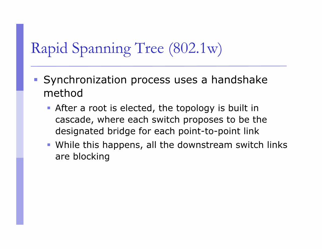
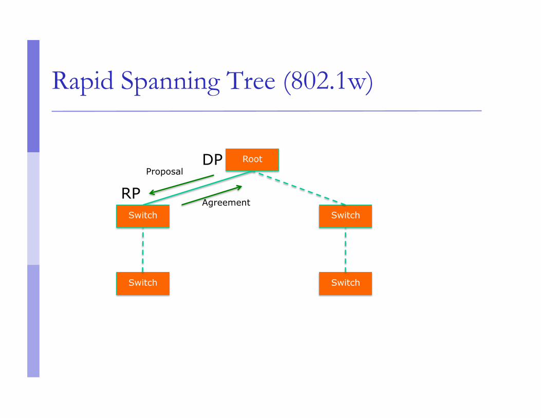
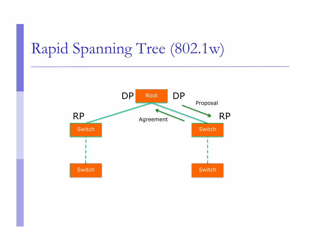
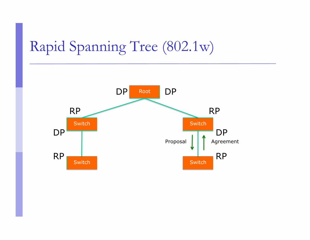
Rapid Spanning Tree (802.1w)
Synchronization process uses a handshake method After a root is elected, the topology is built in
cascade, where each switch proposes to be the designated bridge for each point-to-point link
While this happens, all the downstream switch links are blocking
Rapid Spanning Tree (802.1w)
Root
Switch
Proposal
Switch
Agreement Switch
Switch
DP
RP
Rapid Spanning Tree (802.1w)
Root
Switch
Proposal
Switch
Agreement
Switch
Switch
DP
RP
DP
RP
Rapid Spanning Tree (802.1w)
Root
Switch
Proposal
Switch
Agreement
Switch
Switch
DP
RP
DP
RP
DP
RP
Rapid Spanning Tree (802.1w)
Root
Switch
Proposal
Switch
Agreement
Switch
Switch
DP
RP
DP
RP
DP
RP
DP
RP
Rapid Spanning Tree (802.1w)
Prefer RSTP over STP if you want faster convergence
Always define which ports are edge ports
Multiple Spanning Tree (802.1s)
Allows separate spanning trees per VLAN group Different topologies allow for load balancing
between links Each group of VLANs are assigned to an “instance”
of MST
Compatible with STP and RSTP
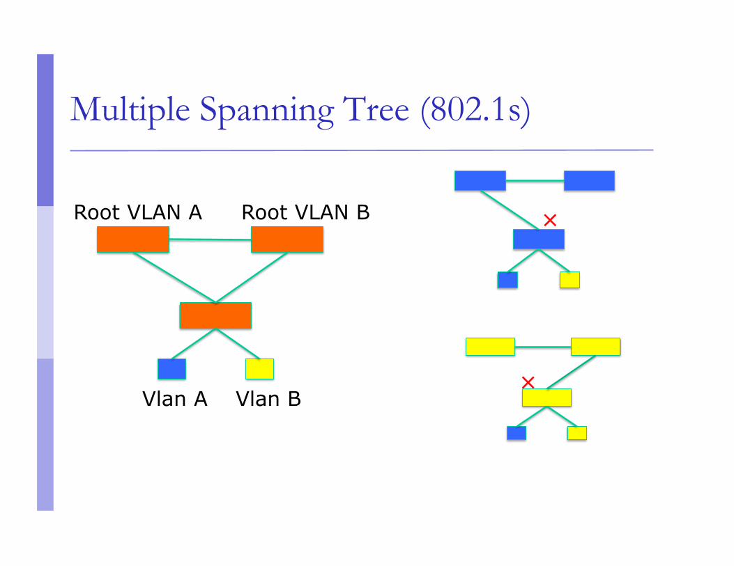
Multiple Spanning Tree (802.1s)
Vlan A Vlan B
Root VLAN A Root VLAN B ✕
✕
Multiple Spanning Tree (802.1s)
MST Region Switches are members of a region if they have the
same set of attributes: MST configuration name MST configuration revision Instance-to-VLAN mapping
A digest of these attributes is sent inside the BPDUs for fast comparison by the switches
One region is usually sufficient
Multiple Spanning Tree (802.1s)
CST = Common Spanning Tree In order to interoperate with other versions of
Spanning Tree, MST needs a common tree that contains all the other islands, including other MST regions
IST = Internal Spanning Tree Internal to the Region, that is Presents the entire region as a single virtual bridge
to the CST outside
Multiple Spanning Tree (802.1s)
MST Instances Groups of VLANs are mapped to particular
Spanning Tree instances These instances will represent the alternative
topologies, or forwarding paths You specify a root and alternate root for each
instance
Multiple Spanning Tree (802.1s)
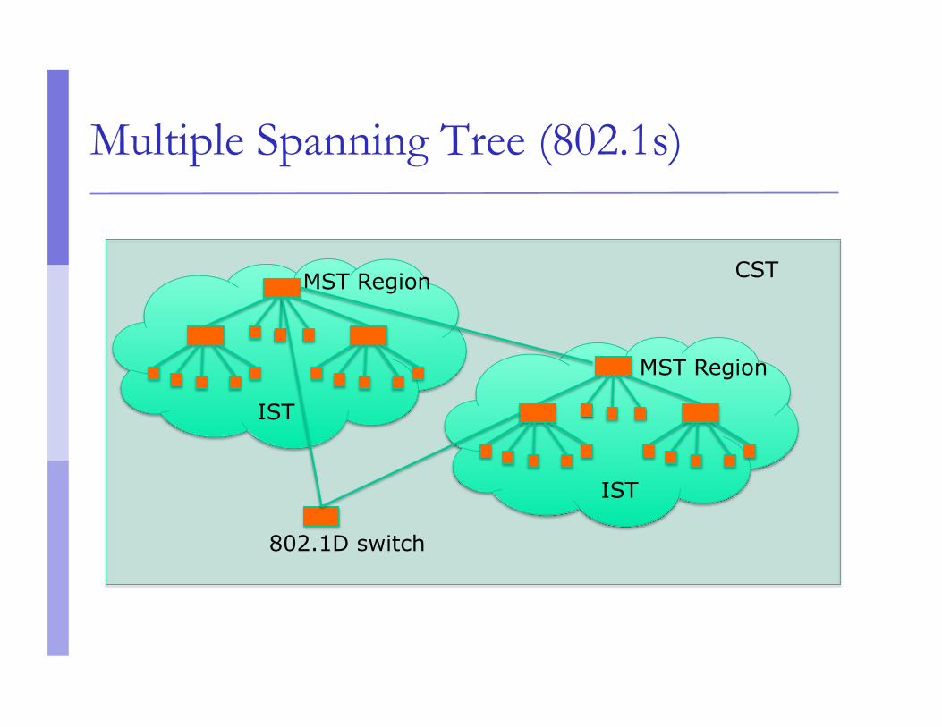
CST MST Region
IST
MST Region
IST
802.1D switch
Multiple Spanning Tree (802.1s)
Design Guidelines Determine relevant forwarding paths, and
distribute your VLANs equally into instances matching these topologies
Assign different root and alternate root switches to each instance
Make sure all switches match region attributes Do not assign VLANs to instance 0, as this is used
by the IST
Selecting Switches
Minimum features: Standards compliance Encrypted management (SSH/HTTPS) VLAN trunking Spanning Tree (RSTP at least) SNMP
At least v2 (v3 has better security) Traps
Selecting Switches
Other recommended features: DHCP Snooping
Prevent end-users from running a rogue DHCP server Happens a lot with little wireless routers (Netgear, Linksys,
etc) plugged in backwards
Uplink ports towards the legitimate DHCP server are defined as “trusted”. If DHCPOFFERs are seen coming from any untrusted port, they are dropped.
Selecting Switches
Other recommended features: Dynamic ARP inspection
A malicious host can perform a man-in-the-middle attack by sending gratuitous ARP responses, or responding to requests with bogus information
Switches can look inside ARP packets and discard gratuitous and invalid ARP packets.
Selecting Switches
Other recommended features: IGMP Snooping:
Switches normally flood multicast frames out every port Snooping on IGMP traffic, the switch can learn which
stations are members of a multicast group, thus forwarding multicast frames only out necessary ports
Very important when users run Norton Ghost, for example.
Network Management
Enable SNMP traps and/or syslog Collect and process in centralized log server
Spanning Tree Changes Duplex mismatches Wiring problems
Monitor configurations Use RANCID to report any changes in the switch
configuration
Network Management
Collect forwarding tables with SNMP Allows you to find a MAC address in your network
quickly You can use simple text files + grep, or a web tool
with DB backend
Enable LLDP (or CDP or similar) Shows how switches are connected to each other
and to other network devices
Documentation
Document where your switches are located Name switch after building name
E.g. building1-sw1
Keep files with physical location Floor, closet number, etc.
Document your edge port connections Room number, jack number, server name