Embed Size (px)
Citation preview
Superabrasive Owner’s Manual – Lavina® 32-S/32-S-HV 6/2014
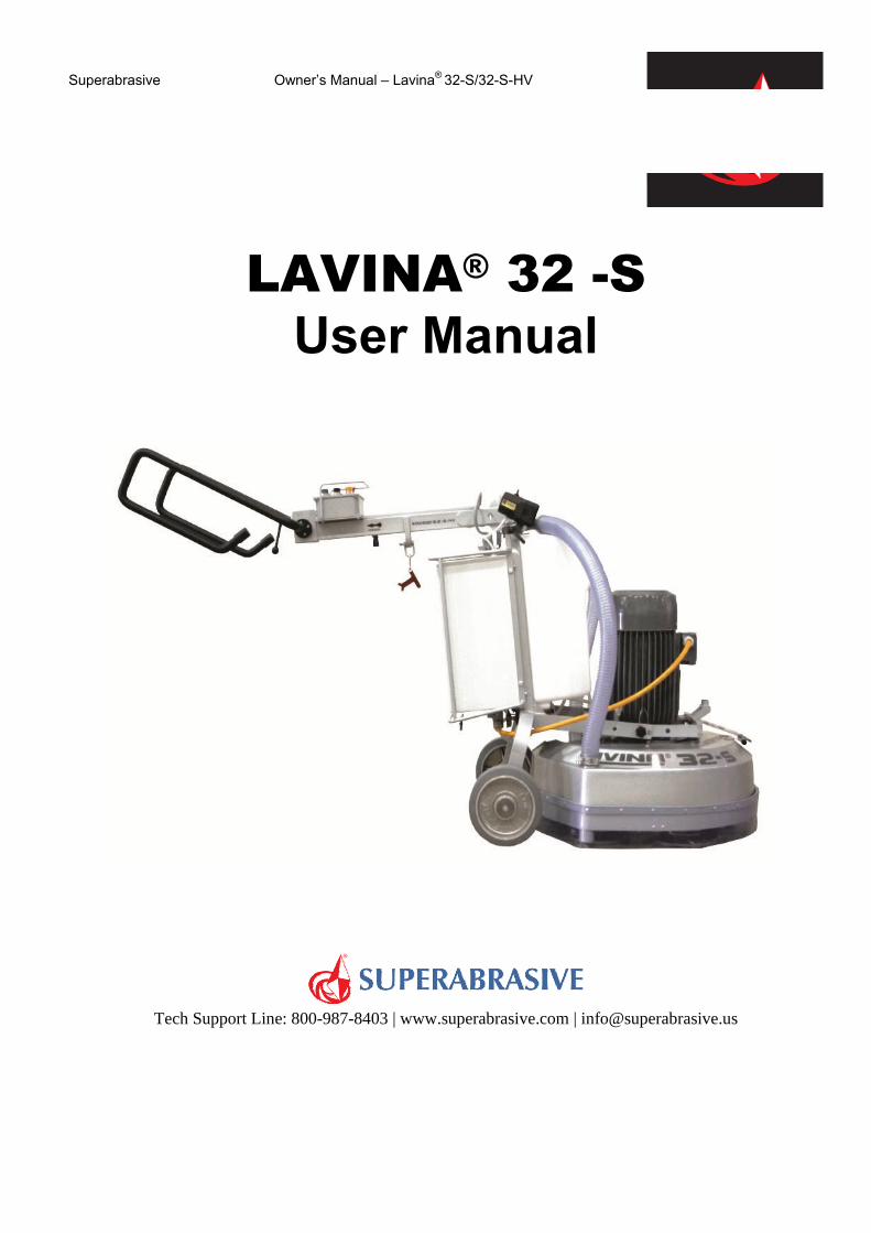
LAVINA® 32 -S User Manual
Tech Support Line: 800-987-8403 | www.superabrasive.com | [email protected]
WARRANTY CARD
A warranty card must be submitted to Superabrasive within 30 days of purchase in order for the foregoing
warranty to apply. See next page for more details on LAVINA warranty and return policies.
Print and mail this form. Or fill out and submit our ONLINE WARRANTY FORM
Customer Information Customer Name
Business Name
Street Address
Street Address line 2
City
State Zip Code
Phone Number
Email Address
Machine Information
Model
Serial Number
Purchased from / Distributor Name
Purchase date
SUPERABRASIVE Inc. 9411 Jackson Trail Road, Hoschton, GA 30548, USA
Tel.: 1 706 658 1122 | Toll Free: 1 800 987 8403 | Fax: 1 706 658 0357 E-mail: [email protected] | www.superabrasive.com
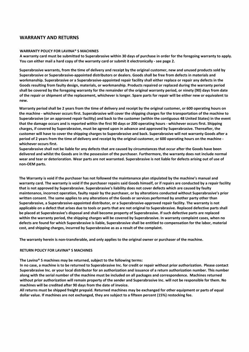
WARRANTY AND RETURNS
WARRANTY POLICY FOR LAVINA® S MACHINES A warranty card must be submitted to Superabrasive within 30 days of purchase in order for the foregoing warranty to apply. You can either mail a hard copy of the warranty card or submit it electronically - see page 2.
Superabrasive warrants, from the time of delivery and receipt by the original customer, new and unused products sold by Superabrasive or Superabrasive-appointed distributors or dealers. Goods shall be free from defects in materials and workmanship. Superabrasive or a Superabrasive-appointed repair facility shall either replace or repair any defects in the Goods resulting from faulty design, materials, or workmanship. Products repaired or replaced during the warranty period shall be covered by the foregoing warranty for the remainder of the original warranty period, or ninety (90) days from date of the repair or shipment of the replacement, whichever is longer. Spare parts for repair will be either new or equivalent to new.
Warranty period shall be 2 years from the time of delivery and receipt by the original customer, or 600 operating hours on the machine - whichever occurs first. Superabrasive will cover the shipping charges for the transportation of the machine to Superabrasive (or an approved repair facility) and back to the customer (within the contiguous 48 United States) in the event that the damage occurs and is reported within the first 90 days or 200 operating hours - whichever occurs first. Shipping charges, if covered by Superabrasive, must be agreed upon in advance and approved by Superabrasive. Thereafter, the customer will have to cover the shipping charges to Superabrasive and back. Superabrasive will not warranty Goods after a period of 2 years from the time of delivery and receipt by the original customer, or 600 operating hours on the machine - whichever occurs first. Superabrasive shall not be liable for any defects that are caused by circumstances that occur after the Goods have been delivered and whilst the Goods are in the possession of the purchaser. Furthermore, the warranty does not include normal wear and tear or deterioration. Wear parts are not warranted. Superabrasive is not liable for defects arising out of use of non-OEM parts.
The warranty herein is non-transferable, and only applies to the original owner or purchaser of the machine.
The Warranty is void if the purchaser has not followed the maintenance plan stipulated by the machine’s manual and warranty card. The warranty is void if the purchaser repairs said Goods himself, or if repairs are conducted by a repair facility that is not approved by Superabrasive. Superabrasive’s liability does not cover defects which are caused by faulty maintenance, incorrect operation, faulty repair by the purchaser, or by alterations conducted without Superabrasive’s prior written consent. The same applies to any alterations of the Goods or services performed by another party other than Superabrasive, a Superabrasive-appointed distributor, or a Superabrasive-approved repair facility. The warranty is not applicable on a defect that arises due to tools or parts that are not original to Superabrasive. Replaced defective parts shall be placed at Superabrasive’s disposal and shall become property of Superabrasive. If such defective parts are replaced within the warranty period, the shipping charges will be covered by Superabrasive. In warranty complaint cases, when no defects are found for which Superabrasive is liable, Superabrasive shall be entitled to compensation for the labor, material cost, and shipping charges, incurred by Superabrasive as as a result of the complaint.
RETURN POLICY FOR LAVINA® S MACHINES
The Lavina® S machines may be returned, subject to the following terms: In no case, a machine is to be returned to Superabrasive Inc. for credit or repair without prior authorization. Please contact Superabrasive Inc. or your local distributor for an authorization and issuance of a return authorization number. This number along with the serial number of the machine must be included on all packages and correspondence. Machines returned without prior authorization will remain property of the sender and Superabrasive Inc. will not be responsible for them. No machines will be credited after 90 days from the date of invoice. All returns must be shipped freight prepaid. Returned machines may be exchanged for other equipment or parts of equal dollar value. If machines are not exchanged, they are subject to a fifteen percent (15%) restocking fee.
Superabrasive Owner’s Manual – Lavina® 32-S/32-S-HV 6/2014
2
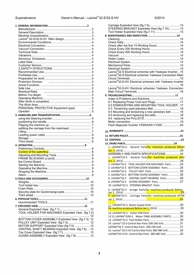
1. GENERAL INFORMATION....................................................3Manufacturer ..................................................................... 3 General Description ........................................................... 3 Machine characteristics ..................................................... 3 Lavina® 32-S/32-S-HV Main design .................................. 3 Environmental Conditions .................................................. 4 Electrical Connection ......................................................... 4 Vacuum Connection .......................................................... 4 Technical Data ................................................................... 4 Vibrations ........................................................................... 4 Sonorous Emissions ......................................................... 4 Label Data ......................................................................... 4 Customer Service .............................................................. 4 2.SAFETY ISTRUCTIONS ................................................ 4 Recommended Use ........................................................... 4 Prohibited Use ................................................................... 4 Preparation for work .......................................................... 5 Protection Devices ..................................................... 5 Arrest Functions ................................................................ 5 Safe Use ............................................................................ 5 Residual Risks ........................................................... 5 Before You Begin ....................................................... 5 Operating Machine ............................................................ 5 After Work is completed..................................................... 5 The Work Area .................................................................. 5 PERSONAL PROTECTIVE Equipment (ppe) ... 5 Operator ................................................................... 5
3. HANDLING AND TRANSPORTATION.......................................6 using the Steering bracket ................................................. 6 positioning the handle ........................................................ 6 Flipping the machine up .................................................... 7 splitting the carriage from the mainhead ............................ 7 Lifting ................................................................................. 7 Leading power cable ......................................................... 8 Storage .............................................................................. 8 Third wheel ........................................................................ 8
4. OPERATION.....................................................................8Preliminary Controls .......................................................... 8 Control of the waterflow ..................................................... 8 Adjusting and Mounting Tools ........................................... 8 FRAME BLOCKING (u-joint] .............................................. 9 the Control Board .............................................................. 9 Starting the Machine .......................................................... 9 Operating the Machine ...................................................... 9 Stopping the Machine ........................................................ 9 Alarm ................................................................................. 9
5.TOOLS AND ACCESSORIES..................................................10Weights............................................................................ 10 Tool holder key ................................................................ 10 Foam Plate ...................................................................... 10 Security plate for Quickchange pads ............................... 10 Third wheel ...................................................................... 10
6. POPULAR TOOLS.............................................................11recommended TOOLS..................................................... 11
7. EXPLODED VIEW.............................................................12General Exploded View (fig.7.1) ..................................... 12 TOOL HOLDER FOR MACHINES Exploded View (fig.7.2) ........................................................................................ 12 BOTTOM COVER ASSEMBLY Exploded View (fig.7.3) 12 PULLEY UNIT Exploded View (fig.7.4) ........................... 12 MOTOR SUPPORT Exploded View (fig.7.5) ................... 12 CENTRAL SHAFT BEARING Exploded View (fig.7.6) ... 13 Top Cover Exploded View (fig.7.7) ................................. 13 GUARD ASSEMBLY Exploded View (fig.7.8) ................. 13
Carriage Exploded View (fig.7.9) ...................................... 13 STEERING BRACKET Exploded View (fig.7.10) ............. 13 Tool Holder Exploded View (fig.7.11) ............................... 13
8. MAINTENANCE AND INSPECTION.......................................14 Cleaning ........................................................................... 14 Check Daily ...................................................................... 14 Check after the first 15 Working Hours ............................. 14 Check Every 200 Working Hours ..................................... 14 Check Every 400 Working Hours ..................................... 14 Vacuum ............................................................................ 14 Water Leaks ..................................................................... 14 Electrical System .............................................................. 14 Mechanical Parts .............................................................. 14 Electrical System .............................................................. 15 Lavina®32-S Electrical schemes with Yaskawa Inverter ... 15 Lavina®32-S Electrical schemes Yaskawa Connection Main Circuit Terminals .............................................................. 15 Lavina®32-S-HV Electrical schemes with Yaskawa Inverter ......................................................................................... 16 Lavina®32-S-HV Electrical schemes Yaskawa Connection Main Circuit Terminals ...................................................... 16
9. TROUBLESHOOTING.........................................................17Index of Problems and Solutions ...................................... 17 9.1 Replacing Power Cord and Plugs ............................... 17 9.2 DISMOUNTING AND MOUNTING TOOL HOLDER .. 17 9.3 Tensioning used planetary Belt ................................. 18 9.4 Mounting and tensioning a new planetary belt ........... 18 9.5 tensioning and replacing the belts .............................. 18 9.6 replacing the PULLEYS ............................................. 19 Motor connection .............................................................. 19 Fault diagnosis Inverter YASKAWA V1000 ...................... 20
10. WARRANTY ..........................................................................23
11. RETURN POLICY............................................... ....................2312. DISPOSAL .................................. ..........................................2313. SPARE PARTS................................................................24
1. LAVINA®32‐S General Parts/for machines produced Before Jan. 1, 2014/....................................................................... 24 ASSEMBLY AND PARTS SPECIFICATIONS .................. 24 1. LAVINA®32‐S General Parts/for machines produced after Jan. 1, 2013/....................................................................... 24 2. LAVINA®32‐S TOOL HOLDER FOR MACHINES Parts ........... 24 3. LAVINA®32‐S BOTTOM COVER ASSEMBLY Parts ............... 254. LAVINA®32‐S PULLEY UNIT Parts ................................... 25 5. LAVINA®32‐S BOTTOM COVER ASSEMBLY Parts ............... 266. LAVINA®32‐S CENTRAL SHAFT BEARING Parts ................. 26 8. LAVINA®32‐S GUARD ASSEMBLY Parts ........................... 27 10. LAVINA®32‐S STEERING BRACKET Parts
9. LAVINA®32‐S Carriage Parts/for machines produced Before Jan.1 , 2014/ ........................................................................29.... 9. LAVINA®32‐S Carriage Parts/for machines produced AFTERJan.1, 2014/............................................................ ...........29
11. LAVINA®32‐S Water Supply Parts ................................... 30 for machine produced Before Jan.1, 2014/............................. 30
13. LAVINA®32‐S motor FAN Parts ...................................... 30 13.11 LAVINA®32M‐S Water TANK ASSEMBLY PARTS ........... 30 12. LAVINA®32‐S Tool Holder Parts ...................................... 30 14. Lavina® 32‐S Control Box Parts 200‐240 Volt .................... 31 LAVINA®32‐S Control Box Parts 200‐240 Volt ....................... 31 15. Lavina® 32‐S‐HV Control Box Parts 380‐480 Volt ............... 32LAVINA®32‐S‐HV Control Box Parts 380‐480 Volt .................. 32
Superabrasive Owner’s Manual – Lavina® 32-S/32-S-HV 6/2014
3
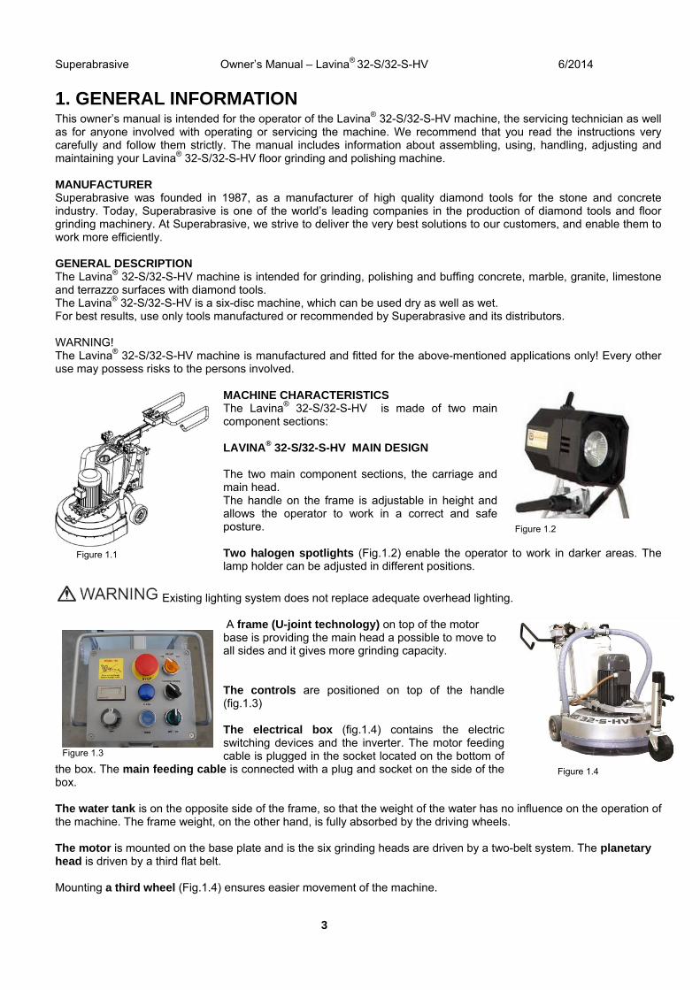
1. GENERAL INFORMATIONThis owner’s manual is intended for the operator of the Lavina® 32-S/32-S-HV machine, the servicing technician as well as for anyone involved with operating or servicing the machine. We recommend that you read the instructions very carefully and follow them strictly. The manual includes information about assembling, using, handling, adjusting and maintaining your Lavina® 32-S/32-S-HV floor grinding and polishing machine.
MANUFACTURER Superabrasive was founded in 1987, as a manufacturer of high quality diamond tools for the stone and concrete industry. Today, Superabrasive is one of the world’s leading companies in the production of diamond tools and floor grinding machinery. At Superabrasive, we strive to deliver the very best solutions to our customers, and enable them to work more efficiently.
GENERAL DESCRIPTION The Lavina® 32-S/32-S-HV machine is intended for grinding, polishing and buffing concrete, marble, granite, limestone and terrazzo surfaces with diamond tools. The Lavina® 32-S/32-S-HV is a six-disc machine, which can be used dry as well as wet. For best results, use only tools manufactured or recommended by Superabrasive and its distributors.
WARNING! The Lavina® 32-S/32-S-HV machine is manufactured and fitted for the above-mentioned applications only! Every other use may possess risks to the persons involved.
MACHINE CHARACTERISTICS The Lavina® 32-S/32-S-HV is made of two main component sections:
LAVINA® 32-S/32-S-HV MAIN DESIGN
The two main component sections, the carriage and main head. The handle on the frame is adjustable in height and allows the operator to work in a correct and safe posture.
Two halogen spotlights (Fig.1.2) enable the operator to work in darker areas. The lamp holder can be adjusted in different positions.
Existing lighting system does not replace adequate overhead lighting.
A frame (U-joint technology) on top of the motor base is providing the main head a possible to move to all sides and it gives more grinding capacity.
The controls are positioned on top of the handle (fig.1.3)
The electrical box (fig.1.4) contains the electric switching devices and the inverter. The motor feeding cable is plugged in the socket located on the bottom of
the box. The main feeding cable is connected with a plug and socket on the side of the box.
The water tank is on the opposite side of the frame, so that the weight of the water has no influence on the operation of the machine. The frame weight, on the other hand, is fully absorbed by the driving wheels.
The motor is mounted on the base plate and is the six grinding heads are driven by a two-belt system. The planetary head is driven by a third flat belt.
Mounting a third wheel (Fig.1.4) ensures easier movement of the machine.
Figure 1.2
Figure 1 1
Figure 1.1
Figure 1.3
Figure 1.4
Superabrasive Owner’s Manual Original Language – Lavina ®32-S /32-S-HV 6/2014
4
ENVIRONMENTAL CONDITIONS The temperature range for operating the Lavina® 32-S/32-S-HV outdoors is between 41°F and 86°F or 5°C and 30°C. Never use the Lavina® 32-S/32-S-HV during rain or snow when working outdoors. When working indoors, always operate the machine in well-ventilated areas.
ELECTRICAL CONNECTION The voltage (Volt) and power (Ampere) are displayed on a label on the electrical control box to avoid any incorrect connection. Refer to these before connecting the power. To avoid electrical shocks, make sure the ground power supply is functioning properly.
VACUUM CONNECTION A connection for a vacuum dust extractor is located on the carriage. The Lavina® 32-S/32-S-HV does not include a vacuum dust extractor. The customer must purchase the vacuum dust extractor separately. The hose of the vacuum extractor must be Ø 76 mm/ 3 Inch and can be glided over the three-way pipe. The vacuum dust extractor must be adapted for floor grinders and have a minimum air displacement of 500m3/h with a negative vacuum of 21 kPa.
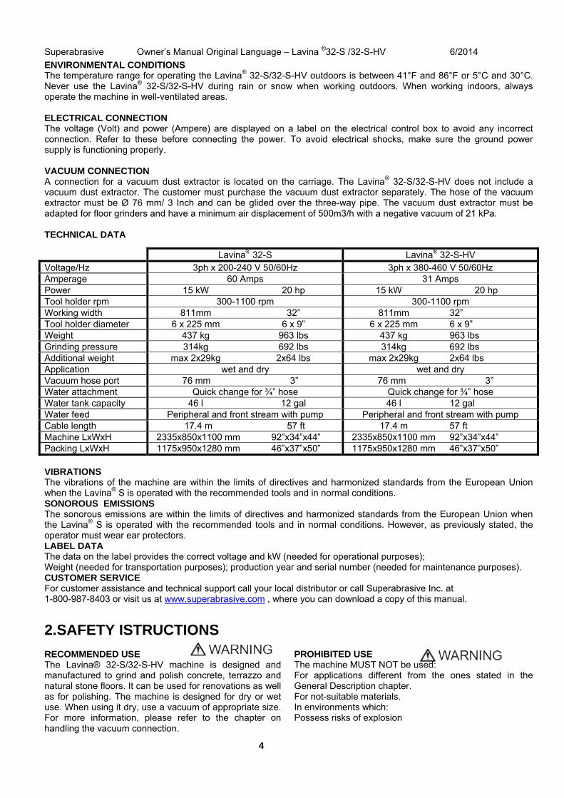
TECHNICAL DATA
VIBRATIONS The vibrations of the machine are within the limits of directives and harmonized standards from the European Union when the Lavina® S is operated with the recommended tools and in normal conditions. SONOROUS EMISSIONS The sonorous emissions are within the limits of directives and harmonized standards from the European Union when the Lavina® S is operated with the recommended tools and in normal conditions. However, as previously stated, the operator must wear ear protectors. LABEL DATA The data on the label provides the correct voltage and kW (needed for operational purposes); Weight (needed for transportation purposes); production year and serial number (needed for maintenance purposes). CUSTOMER SERVICE For customer assistance and technical support call your local distributor or call Superabrasive Inc. at 1-800-987-8403 or visit us at www.superabrasive.com , where you can download a copy of this manual.
2.SAFETY ISTRUCTIONS
RECOMMENDED USE The Lavina® 32-S/32-S-HV machine is designed and manufactured to grind and polish concrete, terrazzo and natural stone floors. It can be used for renovations as well as for polishing. The machine is designed for dry or wet use. When using it dry, use a vacuum of appropriate size. For more information, please refer to the chapter on handling the vacuum connection.
PROHIBITED USE The machine MUST NOT be used: For applications different from the ones stated in the General Description chapter. For not-suitable materials. In environments which: Possess risks of explosion
Lavina® 32-S Lavina® 32-S-HV Voltage/Hz 3ph x 200-240 V 50/60Hz 3ph x 380-460 V 50/60Hz Amperage 60 Amps 31 Amps Power 15 kW 20 hp 15 kW 20 hp Tool holder rpm 300-1100 rpm 300-1100 rpm Working width 811mm 32” 811mm 32” Tool holder diameter 6 x 225 mm 6 x 9” 6 x 225 mm 6 x 9” Weight 437 kg 963 lbs 437 kg 963 lbs Grinding pressure 314kg 692 lbs 314kg 692 lbs Additional weight max 2x29kg 2x64 lbs max 2x29kg 2x64 lbs Application wet and dry wet and dry Vacuum hose port 76 mm 3” 76 mm 3” Water attachment Quick change for ¾” hose Quick change for ¾” hose Water tank capacity 46 l 12 gal 46 l 12 gal Water feed Peripheral and front stream with pump Peripheral and front stream with pump Cable length 17.4 m 57 ft 17.4 m 57 ft Machine LxWxH 2335x850x1100 mm 92”x34”x44” 2335x850x1100 mm 92”x34”x44” Packing LxWxH 1175x950x1280 mm 46”x37”x50” 1175x950x1280 mm 46”x37”x50”
Superabrasive Owner’s Manual Original Language – Lavina ®32-S /32-S-HV 6/2014
5
Possess high concentration of powders or oil substances in the air Possess risks of fire Feature inclement conditions. Possess electromagnetic radiation.
PREPARATION FOR WORK Make sure that: You have closed the work area, so that no person unfamiliar with operating the machine can enter the area The tool plate and tools are adjusted to the machine properly There are no missing parts of the machine The machine is in upright working position The protection devices are working properly. The electrical cable is free to move and follow the machine easily. In order to keep the electrical cable from being damaged, no vehicle should cross the zone where electrical cables are situated. PROTECTION DEVICES The machine is equipped with several protection devices including the following: An emergency stop button A protection skirt and a hood for protecting the tool plates. These devices protect the operator and/or others persons from potential injuries. Do not remove them. On contrary, before using the machine, please ensure that all protectiive devices are mounted and function properly. ARREST FUNCTIONS Functions of arresting of the machine are following: Button to stop the motor (category 1) Emergency button (category 1) SAFE USE The Lavina® 32-S/32-S-HV is designed to eliminate all risks correlated with its use. However, it is not possible to eliminate the risks of an eventual accident with the machine. Unskilled or uninstructed operator may cause correlated residual risks. Such risks are: Position Risks due to operator’s incorrect working position Tangling up Risks due to wearing inappropriate working clothes Training Risks due to lack of operational training NOTE: In order to reduce all consequences of the above-mentioned risks, we advise that machine operators follow the instructions in the manual at all times. RESIDUAL RISKS During the normal operating and maintenance cycles, the operator is exposed to few residual risks, which cannot be eliminated due to the nature of the operations. BEFORE YOU BEGIN Working area must be clear from any debris or objects. A first-time operator must always read the manual and pay attention to all safety instructions. All electric connections and cables must be inspected for potential damages. Ground wire system of the power supply must be also inspected. Perform general daily inspections of the machine and inspect the machine before each use.
Always inspect the safety devices: The emergency break must be clear and working The tool protector must be working The machine must be clean Never operate the machine in the rain! Confirm that there are no missing parts especially after transportation, repair or maintenance. Before filling the water tank with water make sure the machine is not working and the main switch is turned off. Before turning on the machine make sure that the base is placed on the floor, the machine MUST NOT be in an upright position when turned on! OPERATING MACHINE When operating the Lavina® 32-S /32-S-HV, make certain that there is no one, but you around the machine. Never leave the machine unattended while working. The electrical cable must move freely and must be damage-free. The water hose must move freely and must be damage-free. Check if the floor, you work on, is not too uneven. If this is the case, it may damage the machine. AFTER WORK IS COMPLETED Clean the machine and its surroundings properly Empty and clean the water tank Unplug the machine and wind up the electrical cable Store the machine in a safe place THE WORK AREA Make certain that people or vehicles do not enter the work area. Avoid cables and hoses being in the way. Always check the floor for debris
PERSONAL PROTECTIVE EQUIPMENT (PPE)
Always wear safety shoes when working with the machine. Always wear ear protectors when working with the machine. All personnel in the immediate work area must wear safety glasses with side shields. Always wear safety gloves when changing the tools. Always wear clothes suitable for the work environment. OPERATOR The Lavina® 32-S/32-S-HV machine. The operator must know the machine’s work environment. Only one operator at a time can work with the machine. The operator must be properly trained and well instructed prior operating the machine. The operator must understand all the instructions in this manual. The operator must understand and interpret all the drawings and designs in manual. The operator must know all sanitation and safety regulations pertaining to the operation of The operator must have floor grinding experience. The operator must know what to do in case of emergency. The operator must have an adequate technical knowledge and preparation.
Superabrasive Owner’s Manual – Lavina® 32-S/32-S-HV 6/2014
6
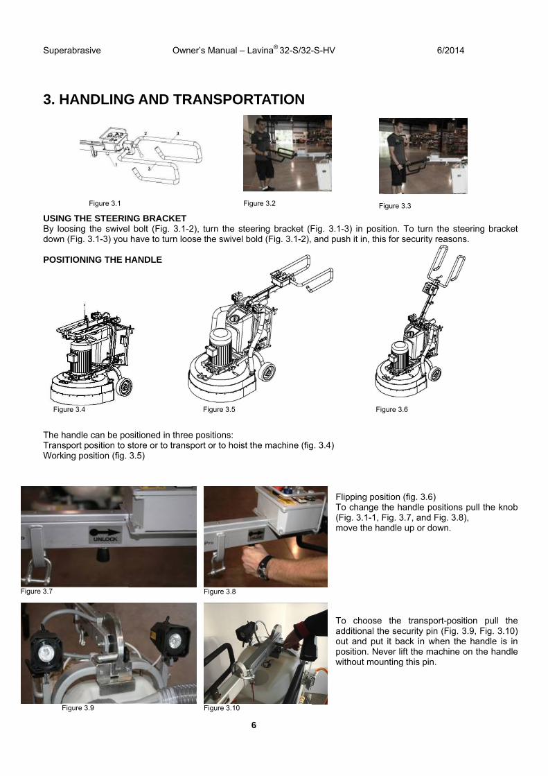
3. HANDLING AND TRANSPORTATION
USING THE STEERING BRACKET By loosing the swivel bolt (Fig. 3.1-2), turn the steering bracket (Fig. 3.1-3) in position. To turn the steering bracket down (Fig. 3.1-3) you have to turn loose the swivel bold (Fig. 3.1-2), and push it in, this for security reasons. POSITIONING THE HANDLE The handle can be positioned in three positions: Transport position to store or to transport or to hoist the machine (fig. 3.4) Working position (fig. 3.5)
Flipping position (fig. 3.6) To change the handle positions pull the knob (Fig. 3.1-1, Fig. 3.7, and Fig. 3.8), move the handle up or down. To choose the transport-position pull the additional the security pin (Fig. 3.9, Fig. 3.10) out and put it back in when the handle is in position. Never lift the machine on the handle without mounting this pin.
Figure 3.4 Figure 3.6 Figure 3.5
Figure 3.7
Figure 3.9
Figure 3.8
Figure 3.10
Figure 3.1 Figure 3.2 Figure 3.3
Superabrasive Owner’s Manual Original Language – Lavina ®32-S /32-S-HV 6/2014
7
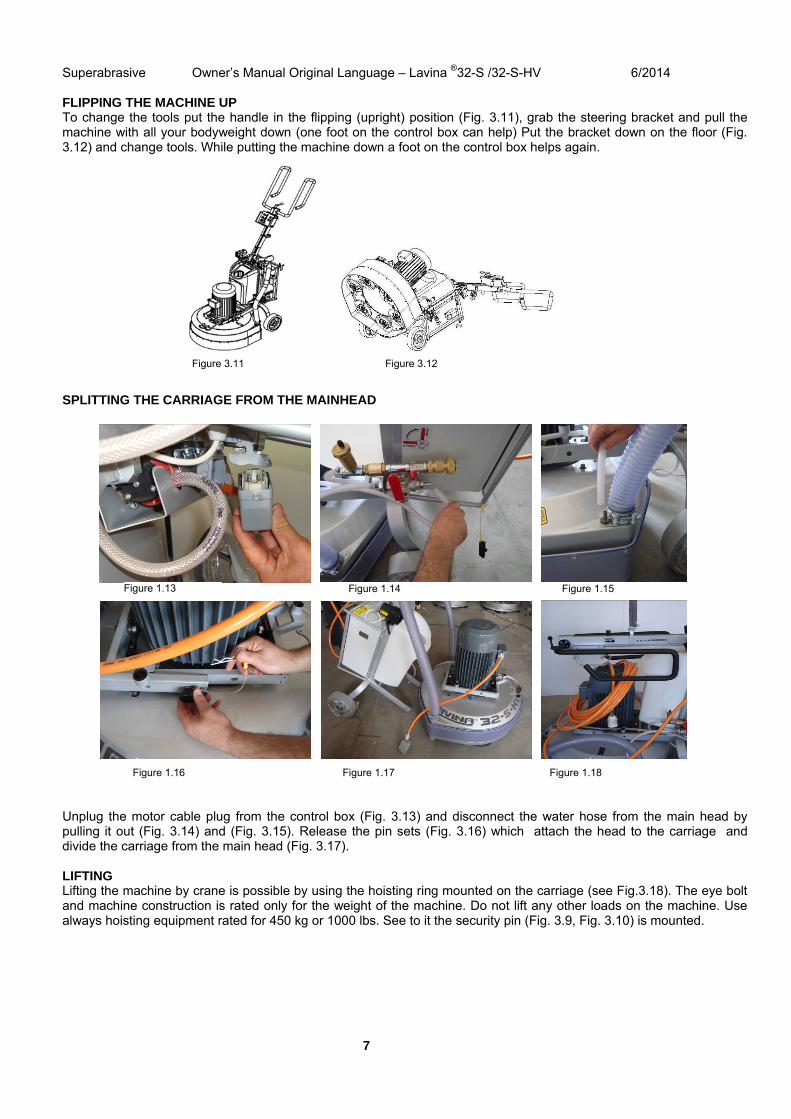
FLIPPING THE MACHINE UP To change the tools put the handle in the flipping (upright) position (Fig. 3.11), grab the steering bracket and pull the machine with all your bodyweight down (one foot on the control box can help) Put the bracket down on the floor (Fig. 3.12) and change tools. While putting the machine down a foot on the control box helps again. SPLITTING THE CARRIAGE FROM THE MAINHEAD Unplug the motor cable plug from the control box (Fig. 3.13) and disconnect the water hose from the main head by pulling it out (Fig. 3.14) and (Fig. 3.15). Release the pin sets (Fig. 3.16) which attach the head to the carriage and divide the carriage from the main head (Fig. 3.17). LIFTING Lifting the machine by crane is possible by using the hoisting ring mounted on the carriage (see Fig.3.18). The eye bolt and machine construction is rated only for the weight of the machine. Do not lift any other loads on the machine. Use always hoisting equipment rated for 450 kg or 1000 lbs. See to it the security pin (Fig. 3.9, Fig. 3.10) is mounted.
Figure 3.12 Figure 3.11
Figure 1.13 Figure 1.14 Figure 1.15
Figure 1.16 Figure 1.17 Figure 1.18
Superabrasive Owner’s Manual Original Language – Lavina ®32-S /32-S-HV 6/2014
8
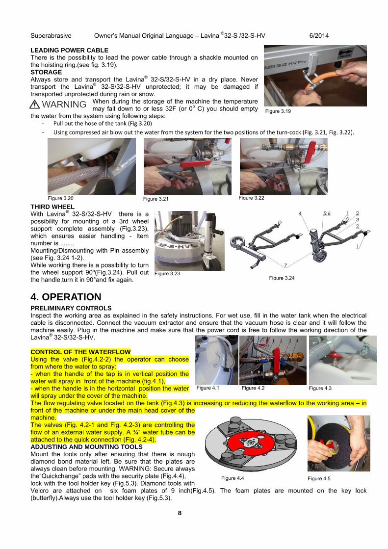
LEADING POWER CABLE There is the possibility to lead the power cable through a shackle mounted on the hoisting ring.(see fig. 3.19). STORAGE Always store and transport the Lavina® 32-S/32-S-HV in a dry place. Never transport the Lavina® 32-S/32-S-HV unprotected; it may be damaged if transported unprotected during rain or snow.
When during the storage of the machine the temperature may fall down to or less 32F (or 0o C) you should empty
the water from the system using following steps: ‐ Pull out the hose of the tank (Fig.3.20)
‐ Using compressed air blow out the water from the system for the two positions of the turn‐cock (Fig. 3.21, Fig. 3.22).
THIRD WHEEL With Lavina® 32-S/32-S-HV there is a possibility for mounting of a 3rd wheel support complete assembly (Fig.3.23), which ensures easier handling - Item number is ........ Mounting/Dismounting with Pin assembly (see Fig. 3.24 1-2). While working there is a possibility to turn the wheel support 90º(Fig.3.24). Pull out the handle,turn it in 90°and fix again.
4. OPERATION PRELIMINARY CONTROLS Inspect the working area as explained in the safety instructions. For wet use, fill in the water tank when the electrical cable is disconnected. Connect the vacuum extractor and ensure that the vacuum hose is clear and it will follow the machine easily. Plug in the machine and make sure that the power cord is free to follow the working direction of the Lavina® 32-S/32-S-HV. CONTROL OF THE WATERFLOW Using the valve (Fig.4.2-2) the operator can choose from where the water to spray: - when the handle of the tap is in vertical position the water will spray in front of the machine (fig.4.1), - when the handle is in the horizontal position the water will spray under the cover of the machine. The flow regulating valve located on the tank (Fig.4.3) is increasing or reducing the waterflow to the working area – in front of the machine or under the main head cover of the machine. The valves (Fig. 4.2-1 and Fig. 4.2-3) are controlling the flow of an external water supply. A ¾” water tube can be attached to the quick connection (Fig. 4.2-4). ADJUSTING AND MOUNTING TOOLS Mount the tools only after ensuring that there is nough diamond bond material left. Be sure that the plates are always clean before mounting. WARNING: Secure always the“Quickchange” pads with the security plate (Fig.4.4), lock with the tool holder key (Fig.5.3). Diamond tools with Velcro are attached on six foam plates of 9 inch(Fig.4.5). The foam plates are mounted on the key lock (butterfly).Always use the tool holder key (Fig.5.3).
Figure 3.19
Figure 4.5 Figure 4.4
Figure 3.24
Figure 3.20 Figure 3.22Figure 3.21
Figure 4.1 Figure 4.2 Figure 4.3
Figure 3.23
Superabrasive Owner’s Manual Original Language – Lavina ®32-S /32-S-HV 6/2014
9
FRAME BLOCKING (U-JOINT] The relation between the working head and the trolley is the frame (U-joint), which allows rotation about two perpendicular axes to better follow the profile of the floor. The movement round one of axis can be blocked with two screws to the plank, mounted on the front of the frame(Fig.4.6). Unscrew the bolts and turn the plank so it fixes the frame to the carrier with its tooth and then tighten the bolts(Fig.4.6). Thus the lateral movement of the machine is blocked.
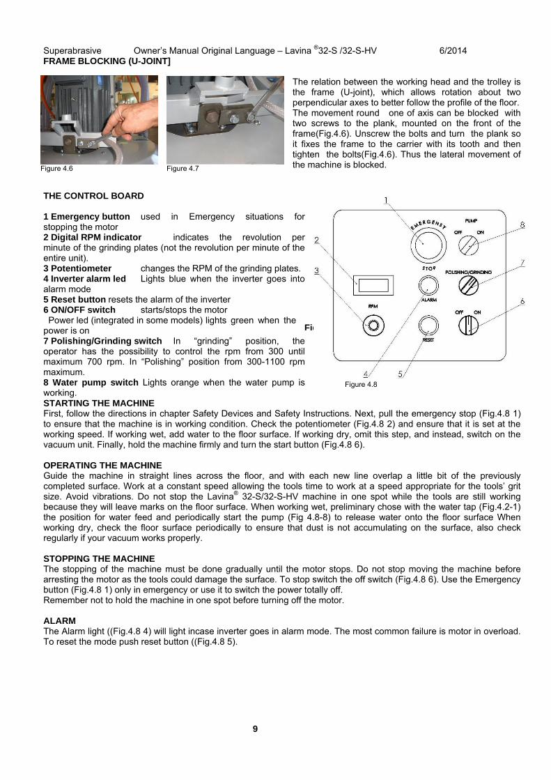
THE CONTROL BOARD 1 Emergency button used in Emergency situations for stopping the motor 2 Digital RPM indicator indicates the revolution per minute of the grinding plates (not the revolution per minute of the entire unit). 3 Potentiometer changes the RPM of the grinding plates. 4 Inverter alarm led Lights blue when the inverter goes into alarm mode 5 Reset button resets the alarm of the inverter 6 ON/OFF switch starts/stops the motor Power led (integrated in some models) lights green when the power is on 7 Polishing/Grinding switch In “grinding” position, the operator has the possibility to control the rpm from 300 until maximum 700 rpm. In “Polishing” position from 300-1100 rpm maximum. 8 Water pump switch Lights orange when the water pump is working. STARTING THE MACHINE First, follow the directions in chapter Safety Devices and Safety Instructions. Next, pull the emergency stop (Fig.4.8 1) to ensure that the machine is in working condition. Check the potentiometer (Fig.4.8 2) and ensure that it is set at the working speed. If working wet, add water to the floor surface. If working dry, omit this step, and instead, switch on the vacuum unit. Finally, hold the machine firmly and turn the start button (Fig.4.8 6). OPERATING THE MACHINE Guide the machine in straight lines across the floor, and with each new line overlap a little bit of the previously completed surface. Work at a constant speed allowing the tools time to work at a speed appropriate for the tools’ grit size. Avoid vibrations. Do not stop the Lavina® 32-S/32-S-HV machine in one spot while the tools are still working because they will leave marks on the floor surface. When working wet, preliminary chose with the water tap (Fig.4.2-1) the position for water feed and periodically start the pump (Fig 4.8-8) to release water onto the floor surface When working dry, check the floor surface periodically to ensure that dust is not accumulating on the surface, also check regularly if your vacuum works properly. STOPPING THE MACHINE The stopping of the machine must be done gradually until the motor stops. Do not stop moving the machine before arresting the motor as the tools could damage the surface. To stop switch the off switch (Fig.4.8 6). Use the Emergency button (Fig.4.8 1) only in emergency or use it to switch the power totally off. Remember not to hold the machine in one spot before turning off the motor. ALARM The Alarm light ((Fig.4.8 4) will light incase inverter goes in alarm mode. The most common failure is motor in overload. To reset the mode push reset button ((Fig.4.8 5).
Figure 4.3
Figure 4.6 Figure 4.7
Figure 4.8
Superabrasive Owner’s Manual Original Language – Lavina ®32-S /32-S-HV 6/2014
10
5.TOOLS AND ACCESSORIESWEIGHTS Superabrasive offers additional weights for increasing the productivity of the machine (Fig.5.1). Each additional weight weighs about 64 lbs or 29 kg. The number of weights you choose to use will vary from none to two. Each individual application, type and condition of surface, power capacity of the outlet, etc. will determine the number of weights you can use without tripping a breaker. The first weight stacks on to three posts on the frame around the outer bowl (Fig.5.2). The second weight stacks onto the first. The additional weights depend on the tools; it is not always possible to add weights. Some tools work too aggressively and the machine can stop. The weight can be ordered with item number A08.00.00.00
TOOL HOLDER KEY The tool holder key (Fig. 5.3) is used for adjusting, mounting and dismounting of the tools. Always use the key for mounting. Item number is A03.00.00.00
FOAM PLATE Diamond tools with Velcro are mounted on the foam plate 9“(Fig.5.4). The foam plate is mounted on the flexible backer plate. Item number is LV-9-FP-S
SECURITY PLATE FOR QUICKCHANGE PADS
Plate (Fig.5.5) used to ensure the “Quickchange” pads. Item number is A38.00.01
THIRD WHEEL There is possibility for mounting of third wheel support complete assembly (Fig.5.6), which ensures easy transportation - Item number is L32-S.04.00.00
Figure 5.3
Figure 5.4
Figure 5.5
Figure 5.6
10
6. POPULAR TOOLS
RECOMMENDED TOOLS
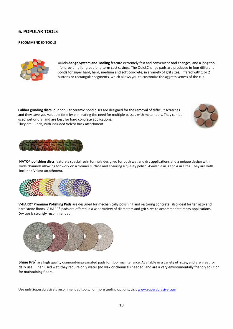
QuickChange System and Tooling feature extremely fast and convenient tool changes, and a long tool life, providing for great long‐term cost savings. The QuickChange pads are produced in four different bonds for super hard, hard, medium and soft concrete, in a variety of grit sizes. Offered with 1 or 2 buttons or rectangular segments, which allows you to customize the aggressiveness of the cut.
Calibra grinding discs: our popular ceramic bond discs are designed for the removal of difficult scratches and they save you valuable time by eliminating the need for multiple passes with metal tools. They can be used wet or dry, and are best for hard concrete applications. They are 3-inch, with included Velcro back attachment.
NATO® polishing discs feature a special resin formula designed for both wet and dry applications and a unique design with wide channels allowing for work on a cleaner surface and ensuring a quality polish. Available in 3 and 4 in sizes. They are with included Velcro attachment.
V‐HARR® Premium Polishing Pads are designed for mechanically polishing and restoring concrete; also ideal for terrazzo and hard stone floors. V‐HARR® pads are offered in a wide variety of diameters and grit sizes to accommodate many applications. Dry use is strongly recommended.
Shine Pro® are high quality diamond‐impregnated pads for floor maintenance. Available in a variety of sizes, and are great for daily use. When used wet, they require only water (no wax or chemicals needed) and are a very environmentally friendly solution for maintaining floors.
Use only Superabrasive’s recommended tools. For more tooling options, visit www.superabrasive.com
Superabrasive Owner’s Manual Original Language – Lavina ®32-S /32-S-HV 6/2014
12
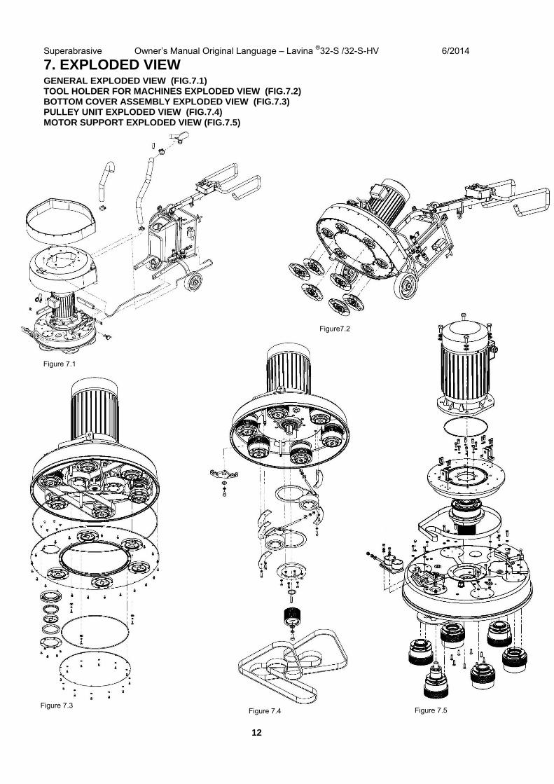
7. EXPLODED VIEWGENERAL EXPLODED VIEW (FIG.7.1) TOOL HOLDER FOR MACHINES EXPLODED VIEW (FIG.7.2) BOTTOM COVER ASSEMBLY EXPLODED VIEW (FIG.7.3) PULLEY UNIT EXPLODED VIEW (FIG.7.4) MOTOR SUPPORT EXPLODED VIEW (FIG.7.5)
Figure 7.1
Figure7.2
Figure 7.4 Figure 7.3
Figure 7.5
Superabrasive Owner’s Manual Original Language – Lavina ®32-S /32-S-HV 6/2014
13
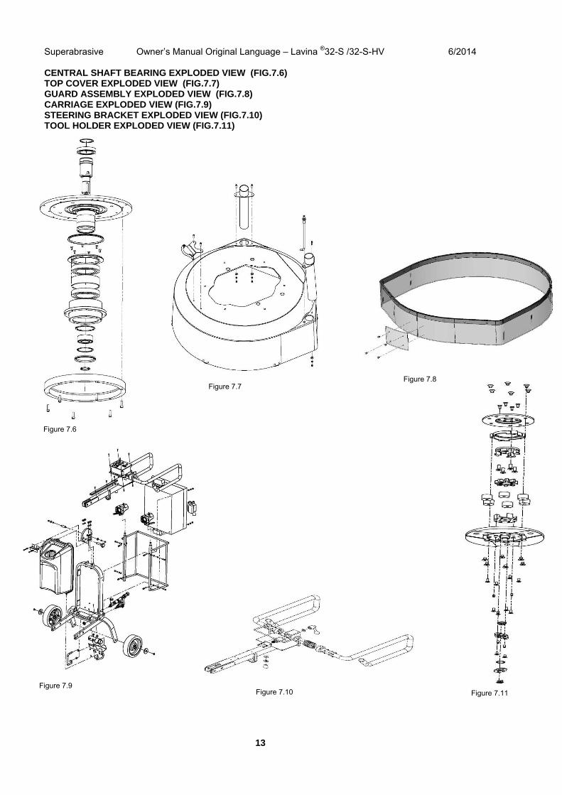
CENTRAL SHAFT BEARING EXPLODED VIEW (FIG.7.6) TOP COVER EXPLODED VIEW (FIG.7.7) GUARD ASSEMBLY EXPLODED VIEW (FIG.7.8) CARRIAGE EXPLODED VIEW (FIG.7.9) STEERING BRACKET EXPLODED VIEW (FIG.7.10) TOOL HOLDER EXPLODED VIEW (FIG.7.11)
Figure 7.10
Figure 7.6
Figure 7.7 Figure 7.8
Figure 7.11 Figure 7.9
Superabrasive Owner’s Manual Original Language – Lavina ®32-S /32-S-HV 6/2014
14
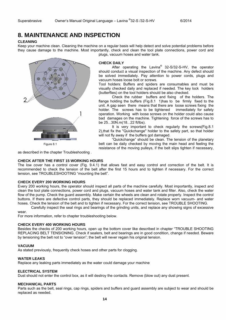
8. MAINTENANCE AND INSPECTION CLEANING Keep your machine clean. Cleaning the machine on a regular basis will help detect and solve potential problems before they cause damage to the machine. Most importantly, check and clean the tool plate connections, power cord and
plugs, vacuum hoses and water tank. CHECK DAILY
After operating the Lavina® 32-S/32-S-HV, the operator should conduct a visual inspection of the machine. Any defect should be solved immediately. Pay attention to power cords, plugs and vacuum hoses loose bolt or screws. Tool holders: Buffers and spiders are consumables and must be visually checked daily and replaced if needed. The key lock holders (butterflies) on the tool holders should be also checked. Check the rubber buffers and fixing of the holders. The flange holding the buffers (Fig.8.1 1)has to be firmly fixed to the unit. A gap seen there means that there are loose screws fixing the holder. The screws has to be tightened immediately for safety operation. Working with loose screws on the holder could also cause bad damages on the machine. Tightening force of the screws has to be 25...30N.m(18...22 ft/lbs). It is very important to check regularly the screws(Fig.8.1 2),that fix the "Quickchange" holder to the safety part, so that holder will not fly away if the buffers got damaged.
“Quickchange” should be clean. The tension of the planetary belt can be daily checked by moving the main head and feeling the resistance of the moving pulleys, if the belt slips tighten if necessary,
as described in the chapter Troubleshooting . CHECK AFTER THE FIRST 15 WORKING HOURS The low cover has a control cover (Fig. 9.4.1) that allows fast and easy control and correction of the belt. It is recommended to check the tension of the belt after the first 15 hours and to tighten if necessary. For the correct tension, see TROUBLESHOOTING “mounting the belt”. CHECK EVERY 200 WORKING HOURS Every 200 working hours, the operator should inspect all parts of the machine carefully. Most importantly, inspect and clean the tool plate connections, power cord and plugs, vacuum hoses and water tank and filter. Also, check the water flow of the pump. Check the guard assembly. Make certain the wheels are clean and rotate properly. Inspect the control buttons. If there are defective control parts, they should be replaced immediately. Replace worn vacuum- and water hoses. Check the tension of the belt and to tighten if necessary. For the correct tension, see TROUBLE SHOOTING.
Carefully inspect the seal rings and bearings of the grinding units, and replace any showing signs of excessive wear. For more information, refer to chapter troubleshooting below. CHECK EVERY 400 WORKING HOURS Besides the checks of 200 working hours, open up the bottom cover like described in chapter “TROUBLE SHOOTING REPLACING BELT TENSIONING. Check if sealers, belt and bearings are in good condition, change if needed. Beware by tensioning the belt not to “over tension”; the belt will never regain his original tension. VACUUM As stated previously, frequently check hoses and other parts for clogging. WATER LEAKS Replace any leaking parts immediately as the water could damage your machine ELECTRICAL SYSTEM Dust should not enter the control box, as it will destroy the contacts. Remove (blow out) any dust present. MECHANICAL PARTS Parts such as the belt, seal rings, cap rings, spiders and buffers and guard assembly are subject to wear and should be replaced as needed.
Figure 8.1
Superabrasive Owner’s Manual Original Language – Lavina ®32-S /32-S-HV 6/2014
15
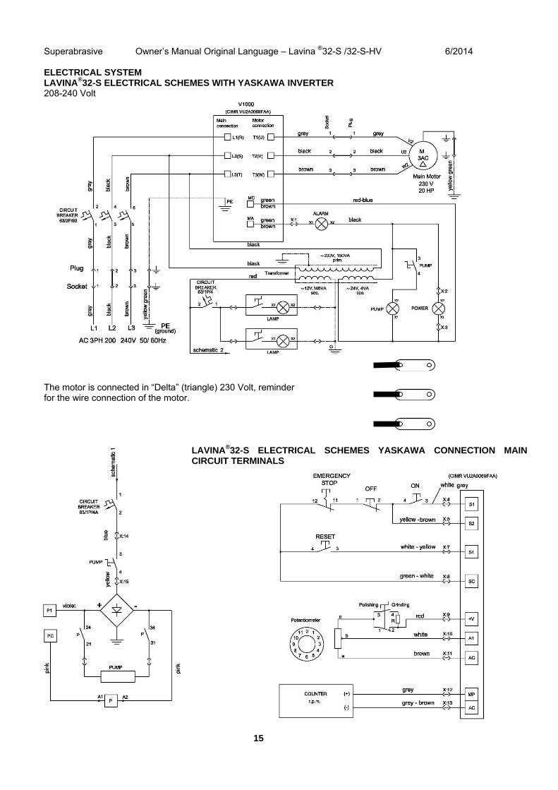
ELECTRICAL SYSTEM LAVINA®32-S ELECTRICAL SCHEMES WITH YASKAWA INVERTER 208-240 Volt
The motor is connected in “Delta” (triangle) 230 Volt, reminder for the wire connection of the motor.
LAVINA®32-S ELECTRICAL SCHEMES YASKAWA CONNECTION MAIN CIRCUIT TERMINALS
Superabrasive Owner’s Manual Original Language – Lavina ®32-S /32-S-HV 6/2014
16
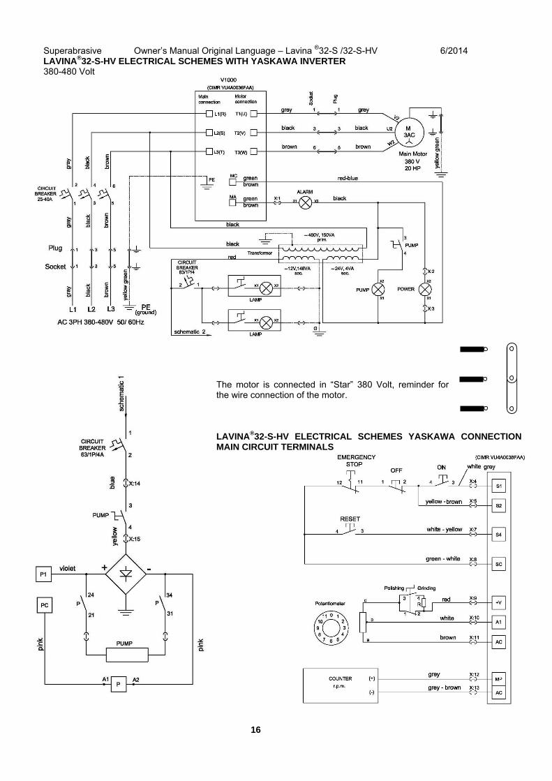
LAVINA®32-S-HV ELECTRICAL SCHEMES WITH YASKAWA INVERTER 380-480 Volt
The motor is connected in “Star” 380 Volt, reminder for the wire connection of the motor. LAVINA®32-S-HV ELECTRICAL SCHEMES YASKAWA CONNECTION MAIN CIRCUIT TERMINALS

Superabrasive Owner’s Manual Original Language – Lavina ®32-S /32-S-HV 6/2014
17
Figure 9.2.7 Figure 9.2.8 Figure 9.2.9 Figure 9.2.10
9. TROUBLESHOOTING INDEX OF PROBLEMS AND SOLUTIONS 9.1 REPLACING POWER CORD AND PLUGS When replacing the power cord or plugs always use cords and plugs with specifications as the original ones. Never use lower quality or different type cord and plugs. 9.2 DISMOUNTING AND MOUNTING TOOL HOLDER TO CHANGE BUFFERS AND SPIDERs, CHANGING V-RINGS AND FELT-RINGS
To check or replace the buffers and the spiders, the tool holders have to be dismounted. Remove the countersunk screws on top of the buffer (Fig.9.2.1). Take the disc off (Fig.9.2.2), the spider can be removed or replaced (Fig.9.2.3). By loosing four Hex cap bolts (Fig.9.2.4), the disc comes loose (Fig.9.2.5) and the buffers can be replaced (Fig.9.2.6). Attention, by mounting use always the “blue” thread locking adhesive, except on the bolts to lock the buffers (Fig.9.2.5). Use always original bolts. Depending on the number (3,4 or 6) of buffers, the holder can be more flexible or rigid.
When the tool holder is dismounted, you can change the sealers (V-Ring and Felt-Ring). Take out Felt-Ring, Adaptor and V-Ring. Before mounting check on which side the adaptor is fitting, remember the correct side. Mount the V-Ring with the smallest lip of the V to inside (Fig.9.2.7) just push the V-ring so the top is on the same level as the pulley top (Fig.9.2.8). Than take the adaptor in the correct way and push the V-Ring down with the adaptor (Fig.9.2.9). The lowest lip of the V-Ring should only barely touch its gliding surface; also never push the V-Ring down with fingers. Mount now the Felt-ring on top (Fig.9.2.10). Close the sealers with the cap (Fig.9.2.11).
Figure 9.2.1 Figure 9.2.2 Figure 9.2.3
Figure 9.2.4 Figure 9.2.5 Figure 9.2.6 Figure 4 3
Figure 9.2.11
Superabrasive Owner’s Manual Original Language – Lavina ®32-S /32-S-HV 6/2014
18
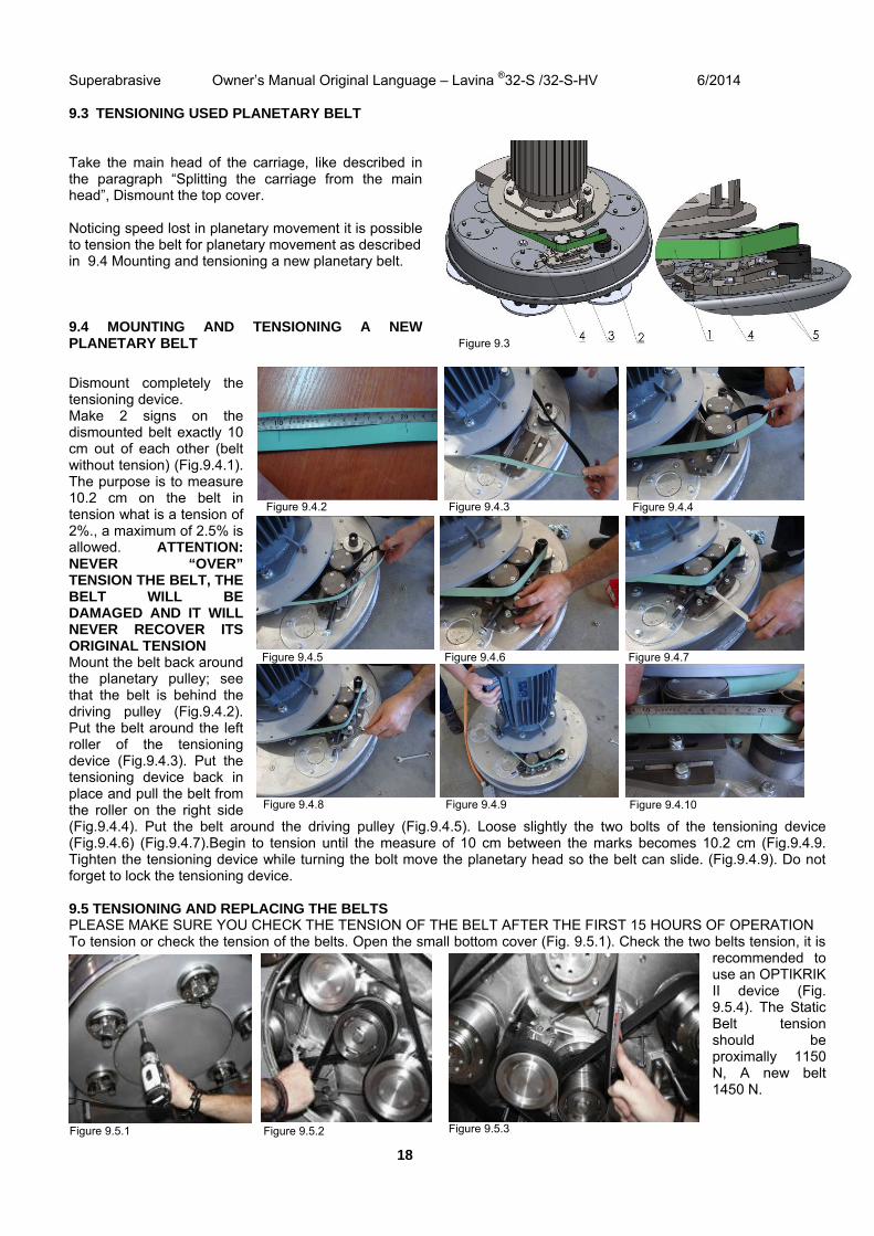
9.3 TENSIONING USED PLANETARY BELT Take the main head of the carriage, like described in the paragraph “Splitting the carriage from the main head”, Dismount the top cover. Noticing speed lost in planetary movement it is possible to tension the belt for planetary movement as described in 9.4 Mounting and tensioning a new planetary belt. 9.4 MOUNTING AND TENSIONING A NEW PLANETARY BELT
Dismount completely the tensioning device. Make 2 signs on the dismounted belt exactly 10 cm out of each other (belt without tension) (Fig.9.4.1). The purpose is to measure 10.2 cm on the belt in tension what is a tension of 2%., a maximum of 2.5% is allowed. ATTENTION: NEVER “OVER” TENSION THE BELT, THE BELT WILL BE DAMAGED AND IT WILL NEVER RECOVER ITS ORIGINAL TENSION Mount the belt back around the planetary pulley; see that the belt is behind the driving pulley (Fig.9.4.2). Put the belt around the left roller of the tensioning device (Fig.9.4.3). Put the tensioning device back in place and pull the belt from the roller on the right side (Fig.9.4.4). Put the belt around the driving pulley (Fig.9.4.5). Loose slightly the two bolts of the tensioning device (Fig.9.4.6) (Fig.9.4.7).Begin to tension until the measure of 10 cm between the marks becomes 10.2 cm (Fig.9.4.9. Tighten the tensioning device while turning the bolt move the planetary head so the belt can slide. (Fig.9.4.9). Do not forget to lock the tensioning device. 9.5 TENSIONING AND REPLACING THE BELTS PLEASE MAKE SURE YOU CHECK THE TENSION OF THE BELT AFTER THE FIRST 15 HOURS OF OPERATION To tension or check the tension of the belts. Open the small bottom cover (Fig. 9.5.1). Check the two belts tension, it is
recommended to use an OPTIKRIK II device (Fig. 9.5.4). The Static Belt tension should be proximally 1150 N, A new belt 1450 N.
Figure 9.4.6 Figure 9.4.5 Figure 9.4.7
Figure 9.4.9 Figure 9.4.8 Figure 9.4.10
Figure 9.4.3 Figure 9.4.2 Figure 9.4.4
Figure 9.3
Figure 9.5.2 Figure 9.5.3 Figure 9.5.1
Superabrasive Owner’s Manual Original Language – Lavina ®32-S /32-S-HV 6/2014
19
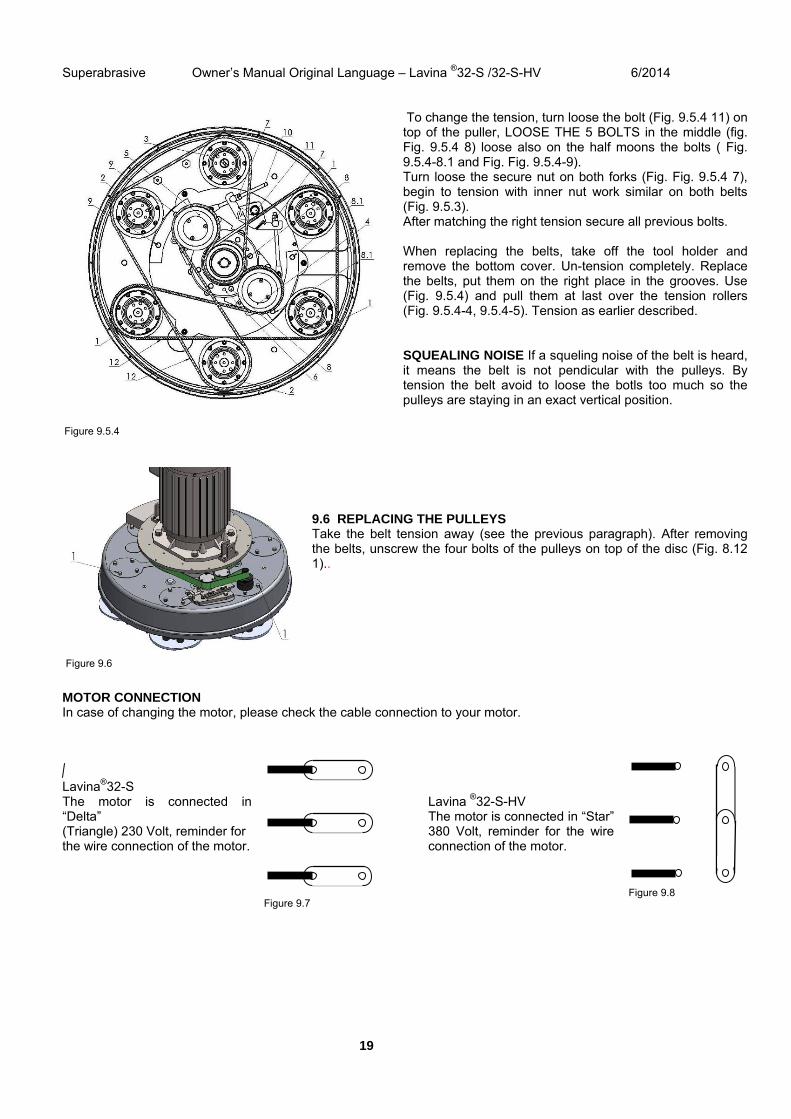
To change the tension, turn loose the bolt (Fig. 9.5.4 11) on top of the puller, LOOSE THE 5 BOLTS in the middle (fig. Fig. 9.5.4 8) loose also on the half moons the bolts ( Fig. 9.5.4-8.1 and Fig. Fig. 9.5.4-9). Turn loose the secure nut on both forks (Fig. Fig. 9.5.4 7), begin to tension with inner nut work similar on both belts (Fig. 9.5.3). After matching the right tension secure all previous bolts. When replacing the belts, take off the tool holder and remove the bottom cover. Un-tension completely. Replace the belts, put them on the right place in the grooves. Use (Fig. 9.5.4) and pull them at last over the tension rollers (Fig. 9.5.4-4, 9.5.4-5). Tension as earlier described. SQUEALING NOISE If a squeling noise of the belt is heard, it means the belt is not pendicular with the pulleys. By tension the belt avoid to loose the botls too much so the pulleys are staying in an exact vertical position.
9.6 REPLACING THE PULLEYS Take the belt tension away (see the previous paragraph). After removing the belts, unscrew the four bolts of the pulleys on top of the disc (Fig. 8.12 1)..
MOTOR CONNECTION In case of changing the motor, please check the cable connection to your motor. Lavina®32-S The motor is connected in “Delta” (Triangle) 230 Volt, reminder for the wire connection of the motor.
Lavina ®32-S-HV The motor is connected in “Star” 380 Volt, reminder for the wire connection of the motor.
Figure 9.7 Figure 9.8
Figure 9.5.4
Figure 9.6
Figure 9.5.4
Superabrasive Owner’s Manual Original Language – Lavina ®32-S /32-S-HV 6/2014
20
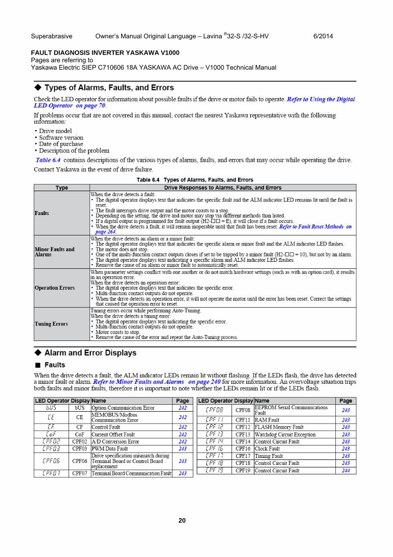
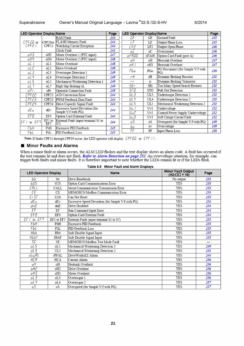
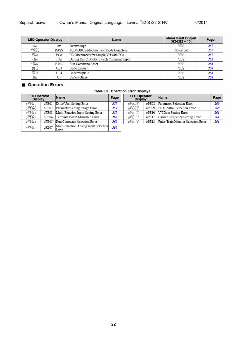
FAULT DIAGNOSIS INVERTER YASKAWA V1000 Pages are referring to Yaskawa Electric SIEP C710606 18A YASKAWA AC Drive – V1000 Technical Manual
Superabrasive Owner’s Manual Original Language – Lavina ®32-S /32-S-HV 6/2014
21
Superabrasive Owner’s Manual Original Language – Lavina ®32-S /32-S-HV 6/2014
22
WARRANTY AND RETURNS
10. WARRANTY POLICY FOR LAVINA® S MACHINESA warranty card must be submitted to Superabrasive within 30 days of purchase in order for the foregoing warranty to apply. You can either mail a hard copy of the warranty card or submit it electronically - see page 2.
Superabrasive warrants, from the time of delivery and receipt by the original customer, new and unused products sold by Superabrasive or Superabrasive-appointed distributors or dealers. Goods shall be free from defects in materials and workmanship. Superabrasive or a Superabrasive-appointed repair facility shall either replace or repair any defects in the Goods resulting from faulty design, materials, or workmanship. Products repaired or replaced during the warranty period shall be covered by the foregoing warranty for the remainder of the original warranty period, or ninety (90) days from date of the repair or shipment of the replacement, whichever is longer. Spare parts for repair will be either new or equivalent to new.
Warranty period shall be 2 years from the time of delivery and receipt by the original customer, or 600 operating hours on the machine - whichever occurs first. Superabrasive will cover the shipping charges for the transportation of the machine to Superabrasive (or an approved repair facility) and back to the customer (within the contiguous 48 United States) in the event that the damage occurs and is reported within the first 90 days or 200 operating hours - whichever occurs first. Shipping charges, if covered by Superabrasive, must be agreed upon in advance and approved by Superabrasive. Thereafter, the customer will have to cover the shipping charges to Superabrasive and back. Superabrasive will not warranty Goods after a period of 2 years from the time of delivery and receipt by the original customer, or 600 operating hours on the machine - whichever occurs first. Superabrasive shall not be liable for any defects that are caused by circumstances that occur after the Goods have been delivered and whilst the Goods are in the possession of the purchaser. Furthermore, the warranty does not include normal wear and tear or deterioration. Wear parts are not warranted. Superabrasive is not liable for defects arising out of use of non-OEM parts.
The warranty herein is non-transferable, and only applies to the original owner or purchaser of the machine.
The Warranty is void if the purchaser has not followed the maintenance plan stipulated by the machine’s manual and warranty card. The warranty is void if the purchaser repairs said Goods himself, or if repairs are conducted by a repair facility that is not approved by Superabrasive. Superabrasive’s liability does not cover defects which are caused by faulty maintenance, incorrect operation, faulty repair by the purchaser, or by alterations conducted without Superabrasive’s prior written consent. The same applies to any alterations of the Goods or services performed by another party other than Superabrasive, a Superabrasive-appointed distributor, or a Superabrasive-approved repair facility. The warranty is not applicable on a defect that arises due to tools or parts that are not original to Superabrasive. Replaced defective parts shall be placed at Superabrasive’s disposal and shall become property of Superabrasive. If such defective parts are replaced within the warranty period, the shipping charges will be covered by Superabrasive. In warranty complaint cases, when no defects are found for which Superabrasive is liable, Superabrasive shall be entitled to compensation for the labor, material cost, and shipping charges, incurred by Superabrasive as as a result of the complaint.
11. RETURN POLICY FOR LAVINA® S MACHINES
The Lavina® S machines may be returned, subject to the following terms: In no case, a machine is to be returned to Superabrasive Inc. for credit or repair without prior authorization. Please contact Superabrasive Inc. or your local distributor for an authorization and issuance of a return authorization number. This number along with the serial number of the machine must be included on all packages and correspondence. Machines returned without prior authorization will remain property of the sender and Superabrasive Inc. will not be responsible for them. No machines will be credited after 90 days from the date of invoice. All returns must be shipped freight prepaid. Returned machines may be exchanged for other equipment or parts of equal dollar value. If machines are not exchanged, they are subject to a fifteen percent (15%) restocking fee.
If your machine after time is not usable or needs to be replaced, send the machine back to Superabrasive or a local distributor, where a professional disposal complying with the environment laws and directives is guaranteed.
12. DISPOSAL
23
Superabrasive Owner’s Manual Original Language – Lavina ®32-S /32-S-HV 6/2014
24
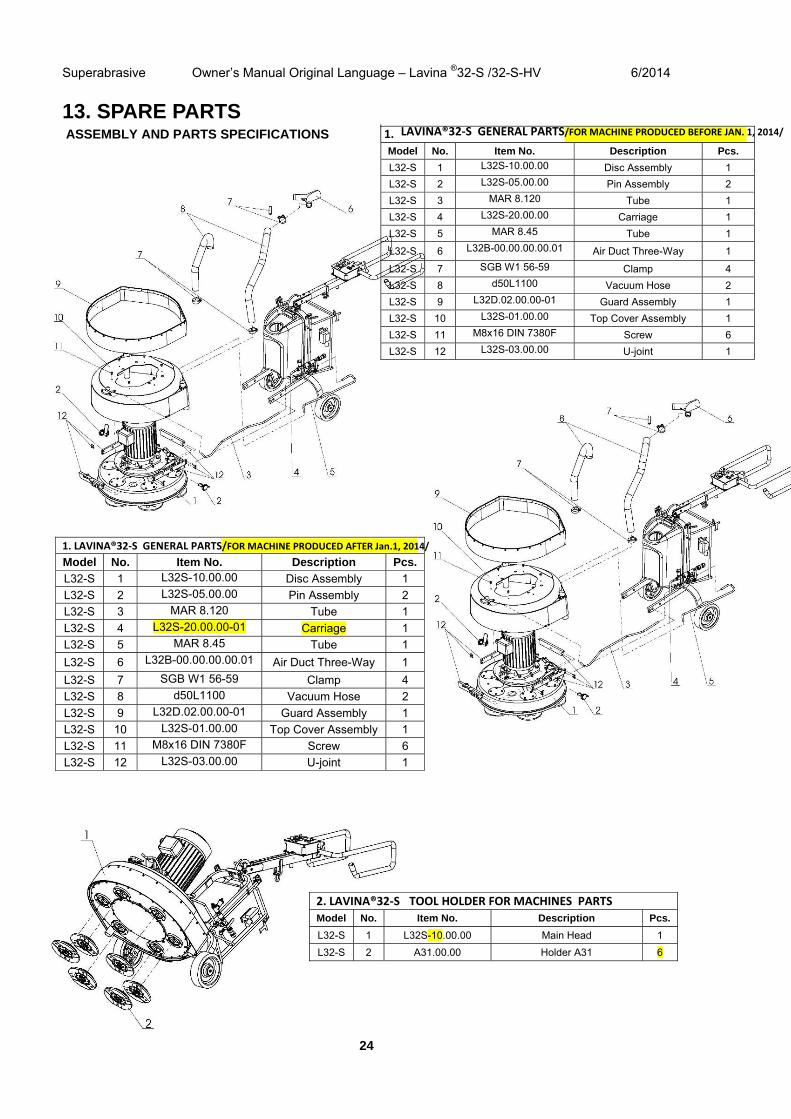
13. SPARE PARTS ASSEMBLY AND PARTS SPECIFICATIONS 1. LAVINA®32‐S GENERAL PARTS/FOR MACHINE PRODUCED BEFORE JAN. 1, 2014/
Model No. Item No. Description Pcs.
L32-S 1 L32S-10.00.00 Disc Assembly 1
L32-S 2 L32S-05.00.00 Pin Assembly 2
L32-S 3 MAR 8.120 Tube 1
L32-S 4 L32S-20.00.00 Carriage 1
L32-S 5 MAR 8.45 Tube 1
L32-S 6 L32B-00.00.00.00.01 Air Duct Three-Way 1
L32-S 7 SGB W1 56-59 Clamp 4
L32-S 8 d50L1100 Vacuum Hose 2
L32-S 9 L32D.02.00.00-01 Guard Assembly 1
L32-S 10 L32S-01.00.00 Top Cover Assembly 1
L32-S 11 M8x16 DIN 7380F Screw 6
L32-S 12 L32S-03.00.00 U-joint 1
1. LAVINA®32‐S GENERAL PARTS/FOR MACHINE PRODUCED AFTER Jan.1, 2014/Model No. Item No. Description Pcs.
L32-S 1 L32S-10.00.00 Disc Assembly 1
L32-S 2 L32S-05.00.00 Pin Assembly 2
L32-S 3 MAR 8.120 Tube 1
L32-S 4 L32S-20.00.00-01 Carriage 1
L32-S 5 MAR 8.45 Tube 1
L32-S 6 L32B-00.00.00.00.01 Air Duct Three-Way 1
L32-S 7 SGB W1 56-59 Clamp 4
L32-S 8 d50L1100 Vacuum Hose 2
L32-S 9 L32D.02.00.00-01 Guard Assembly 1
L32-S 10 L32S-01.00.00 Top Cover Assembly 1
L32-S 11 M8x16 DIN 7380F Screw 6
L32-S 12 L32S-03.00.00 U-joint 1
2. LAVINA®32‐S TOOL HOLDER FOR MACHINES PARTS
Model No. Item No. Description Pcs.
L32-S 1 L32S-10.00.00 Main Head 1
L32-S 2 A31.00.00 Holder A31 6
Superabrasive Owner’s Manual Original Language – Lavina ®32-S /32-S-HV 6/2014
25
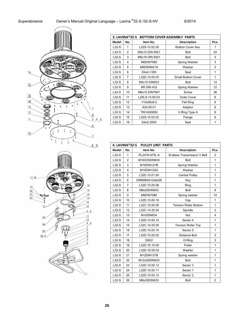
3. LAVINA®32‐S BOTTOM COVER ASSEMBLY PARTS
Model No. Item No. Description Pcs.
L32-S 1 L32S-10.02.00 Bottom Cover Ass. 1
L32-S 2 M5x12 DIN 6921 Bolt 24
L32-S 3 M6x16 DIN 6921 Bolt 3
L32-S 4 M6DIN7980 Spring Washer 3
L32-S 5 M6DIN9021A Washer 3
L32-S 6 D4x2-1350 Seal 1
L32-S 7 L32D.10.00.03 Small Bottom Cover 1
L32-S 8 М5х10 DIN933 Bolt 12
L32-S 9 M5 DIN 433 Spring Washer 12
L32-S 10 М6х10 DIN7991 Screw 36
L32-S 11 L25LS-14.00.03 Outer Cover 6
L32-S 12 110x90x8.5 Felt Ring 6
L32-S 13 A34.00.01 Adaptor 6
L32-S 14 TWVA00800 V-Ring Type A 6
L32-S 15 L32S-10.02.02 Flange 6
L32-S 16 D4x2-2500 Seal 1
4. LAVINA®32‐S PULLEY UNIT PARTSModel No. Item No. Description Pcs.
L32-S 1 PL2476-975L-9 Endless Transmission V Belt 2
L32-S 2 M16X35DIN933 Bolt 1
L32-S 3 M16DIN127B Spring Washer 1
L32-S 4 M16DIN125A Washer 1
L32-S 5 L32D.10.01.00 Central Pulley 1
L32-S 6 DIN6885A12x8x56 Key 1
L32-S 7 L32D.10.00.06 Ring 1
L32-S 8 M8x25DIN933 Bolt 8
L32-S 9 M8DIN7980 Spring washer 10
L32-S 10 L32D.10.00.18 Cap 1
L32-S 11 L32C.15.00.00 Tension Roller Bottom 1
L32-S 12 L32C.14.20.04 Spindle 2
L32-S 13 M10DIN934 Nut 4
L32-S 14 L32D.10.00.14 Sector 4 1
L32-S 15 L32C.14.00.00 Tension Roller Top 1
L32-S 16 L32D.10.00.15 Sector 5 1
L32-S 17 L32D.10.00.02 Distance Bolt 3
L32-S 18 D6X2 O-Ring 3
L32-S 19 L32D.16.10.00 Puller 1
L32-S 20 L32D-16.00.03 Washer 1
L32-S 21 M12DIN127B Spring washer 1
L32-S 22 M12x20DIN933 Bolt 1
L32-S 23 L32D.10.00.13 Sector 3 1
L32-S 24 L32D.10.00.11 Sector 1 1
L32-S 25 L32D.10.00.12 Sector 2 1
L32-S 26 M8x35DIN933 Bolt 2

Superabrasive Owner’s Manual Original Language – Lavina ®32-S /32-S-HV 6/2014
26
5. LAVINA®32‐S BOTTOM COVER ASSEMBLY PARTS
Model No. Item No. Description Pcs.
L32-S 1 M16X35DIN933 Bolt 4
L32-S 2 M16DIN127B Spring Washer 4
L32-S 3 M16DIN125A Washer 4
L32-S 4 S321 Electro Motor 1
L32-S 5 M8X20DIN912 Screw 14
L32-S 6 M8DIN7980 Spring Washer 14
L32-S 7 L32-01.02.00.00.01 Fork 2
L32-S 8 L32S-11.00.00 Central shaft bearing 1
L32-S 8.1 L32S-11.12.00 Disc Assembly with Planetary Pulley 1
L32-S 9 TC-20 EF L1730x30x2 Endless Transmission Flat Belt 1
L32-S 10 L32D.12.00.00-02 Pulley Top Belt 2
L32-S 11 L32D.12.00.00-01 Pulley Bottom Belt 3
L32-S 12 L32S-13.00.00 Pulley Unit 1
L32-S 13 L32D.10.00.01 Disc 1
L32-S 14 L32S-17.00.00 Planetary Tensioning Unit 1
L32-S 15 D4x2-850 Seal 1
L32-S 16 M8X30DIN7991 Screw 8
6. LAVINA®32‐S CENTRAL SHAFT BEARING PARTSModel No. Item No. Description Pcs.
L32-S 1 B65DIN471 Retaining Ring 1
L32-S 2 6013 Roller Assembly 1
L32-S 3 L32D.11.00.05 Extension Shaft 1
L32-S 4 L32S-11.02.00 Disc Assembly 1
L32-S 5 TWVL01700 V-Seal 1
L32-S 6 M6x16DIN7991 Screw 6
L32-S 7 L32D.11.00.03 Cap 1
L32-S 8 6019 Roller Assembly 2
L32-S 9 L32D.11.00.04 Spacer 1
L32-S 10 L32D.11.01.00 Housing 1
L32-S 11 B95DIN471 Retaining Ring 1
L32-S 12 3208 Roller Assembly 1
L32-S 13 A80DIN472 Retaining Ring 1
L32-S 14 TWVA00950 V-Seal 1
L32-S 15 L32D.11.00.06 Ring 1
L32-S 16 L32S.11.00.17 Planetary Pulley 1
L32-S 17 M8x30 DIN 912 Screw 6
Superabrasive Owner’s Manual Original Language – Lavina ®32-S /32-S-HV 6/2014
27
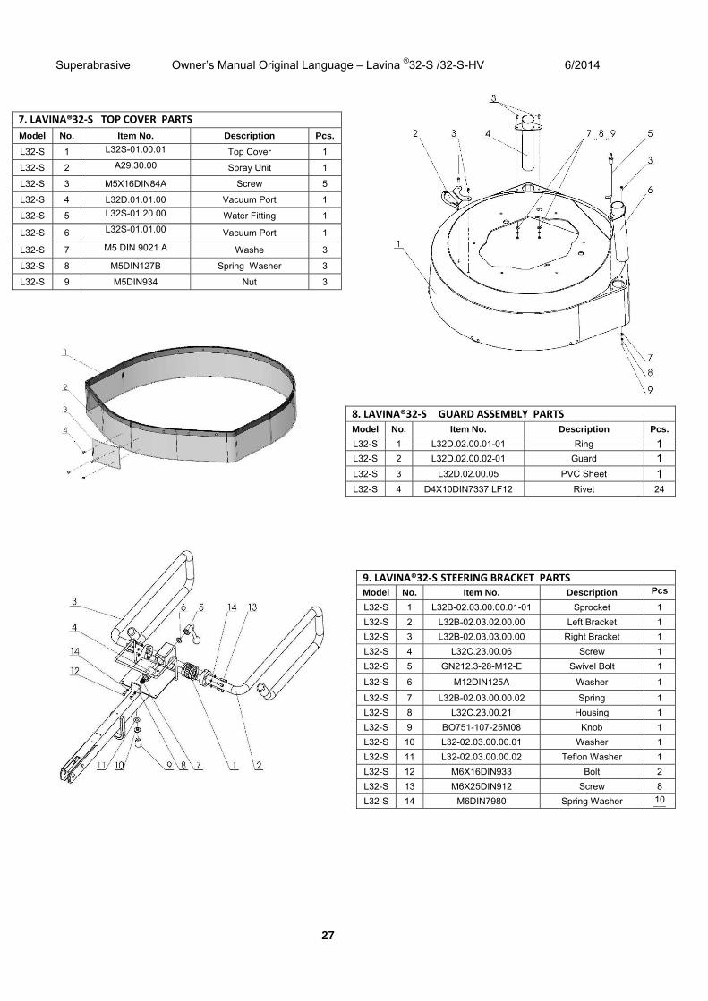
7. LAVINA®32‐S TOP COVER PARTS
Model No. Item No. Description Pcs.
L32-S 1 L32S-01.00.01 Top Cover 1
L32-S 2 А29.30.00 Spray Unit 1
L32-S 3 M5X16DIN84A Screw 5
L32-S 4 L32D.01.01.00 Vacuum Port 1
L32-S 5 L32S-01.20.00 Water Fitting 1
L32-S 6 L32S-01.01.00 Vacuum Port 1
L32-S 7 M5 DIN 9021 A Washe 3
L32-S 8 M5DIN127B Spring Washer 3
L32-S 9 M5DIN934 Nut 3
8. LAVINA®32‐S GUARD ASSEMBLY PARTS
Model No. Item No. Description Pcs.
L32-S 1 L32D.02.00.01-01 Ring 1 L32-S 2 L32D.02.00.02-01 Guard 1 L32-S 3 L32D.02.00.05 PVC Sheet 1 L32-S 4 D4X10DIN7337 LF12 Rivet 24
9. LAVINA®32‐S STEERING BRACKET PARTSModel No. Item No. Description Pcs
L32-S 1 L32B-02.03.00.00.01-01 Sprocket 1
L32-S 2 L32B-02.03.02.00.00 Left Bracket 1
L32-S 3 L32B-02.03.03.00.00 Right Bracket 1
L32-S 4 L32C.23.00.06 Screw 1
L32-S 5 GN212.3-28-M12-E Swivel Bolt 1
L32-S 6 M12DIN125A Washer 1
L32-S 7 L32B-02.03.00.00.02 Spring 1
L32-S 8 L32C.23.00.21 Housing 1
L32-S 9 BO751-107-25M08 Knob 1
L32-S 10 L32-02.03.00.00.01 Washer 1
L32-S 11 L32-02.03.00.00.02 Teflon Washer 1
L32-S 12 M6X16DIN933 Bolt 2
L32-S 13 M6X25DIN912 Screw 8
L32-S 14 M6DIN7980 Spring Washer 10
Superabrasive Owner’s Manual Original Language – Lavina ®32-S /32-S-HV 6/2014
28
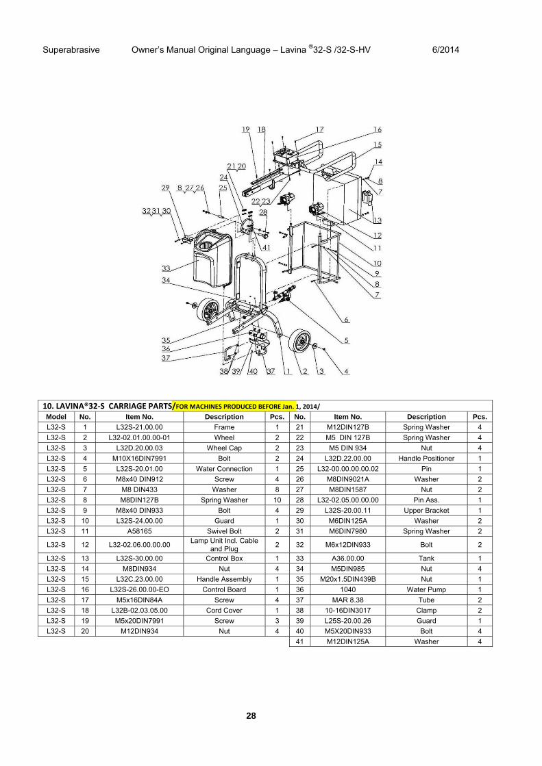
10. LAVINA®32‐S CARRIAGE PARTS/FOR MACHINES PRODUCED BEFORE Jan. 1, 2014/Model No. Item No. Description Pcs. No. Item No. Description Pcs.
L32-S 1 L32S-21.00.00 Frame 1 21 M12DIN127B Spring Washer 4
L32-S 2 L32-02.01.00.00-01 Wheel 2 22 M5 DIN 127B Spring Washer 4
L32-S 3 L32D.20.00.03 Wheel Cap 2 23 M5 DIN 934 Nut 4
L32-S 4 M10X16DIN7991 Bolt 2 24 L32D.22.00.00 Handle Positioner 1
L32-S 5 L32S-20.01.00 Water Connection 1 25 L32-00.00.00.00.02 Pin 1
L32-S 6 M8x40 DIN912 Screw 4 26 M8DIN9021A Washer 2
L32-S 7 M8 DIN433 Washer 8 27 M8DIN1587 Nut 2
L32-S 8 M8DIN127B Spring Washer 10 28 L32-02.05.00.00.00 Pin Ass. 1
L32-S 9 М8х40 DIN933 Bolt 4 29 L32S-20.00.11 Upper Bracket 1
L32-S 10 L32S-24.00.00 Guard 1 30 M6DIN125A Washer 2
L32-S 11 A58165 Swivel Bolt 2 31 M6DIN7980 Spring Washer 2
L32-S 12 L32-02.06.00.00.00 Lamp Unit Incl. Cable
and Plug 2 32 M6x12DIN933 Bolt 2
L32-S 13 L32S-30.00.00 Control Box 1 33 A36.00.00 Tank 1
L32-S 14 M8DIN934 Nut 4 34 M5DIN985 Nut 4
L32-S 15 L32C.23.00.00 Handle Assembly 1 35 M20x1.5DIN439B Nut 1
L32-S 16 L32S-26.00.00-EO Control Board 1 36 1040 Water Pump 1
L32-S 17 M5x16DIN84A Screw 4 37 MAR 8.38 Tube 2
L32-S 18 L32B-02.03.05.00 Cord Cover 1 38 10-16DIN3017 Clamp 2
L32-S 19 M5x20DIN7991 Screw 3 39 L25S-20.00.26 Guard 1
L32-S 20 M12DIN934 Nut 4 40 M5X20DIN933 Bolt 4
41 M12DIN125A Washer 4
Superabrasive Owner’s Manual Original Language – Lavina ®32-S /32-S-HV 6/2014
29
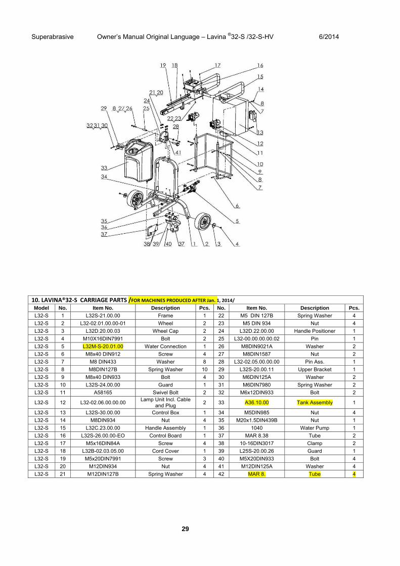
10. LAVINA®32‐S CARRIAGE PARTS /FOR MACHINES PRODUCED AFTER Jan. 1, 2014/Model No. Item No. Description Pcs. No. Item No. Description Pcs.
L32-S 1 L32S-21.00.00 Frame 1 22 M5 DIN 127B Spring Washer 4
L32-S 2 L32-02.01.00.00-01 Wheel 2 23 M5 DIN 934 Nut 4
L32-S 3 L32D.20.00.03 Wheel Cap 2 24 L32D.22.00.00 Handle Positioner 1
L32-S 4 M10X16DIN7991 Bolt 2 25 L32-00.00.00.00.02 Pin 1
L32-S 5 L32M-S-20.01.00 Water Connection 1 26 M8DIN9021A Washer 2
L32-S 6 M8x40 DIN912 Screw 4 27 M8DIN1587 Nut 2
L32-S 7 M8 DIN433 Washer 8 28 L32-02.05.00.00.00 Pin Ass. 1
L32-S 8 M8DIN127B Spring Washer 10 29 L32S-20.00.11 Upper Bracket 1
L32-S 9 М8х40 DIN933 Bolt 4 30 M6DIN125A Washer 2
L32-S 10 L32S-24.00.00 Guard 1 31 M6DIN7980 Spring Washer 2
L32-S 11 A58165 Swivel Bolt 2 32 M6x12DIN933 Bolt 2
L32-S 12 L32-02.06.00.00.00 Lamp Unit Incl. Cable
and Plug 2 33 A36.10.00 Tank Assembly 1
L32-S 13 L32S-30.00.00 Control Box 1 34 M5DIN985 Nut 4
L32-S 14 M8DIN934 Nut 4 35 M20x1.5DIN439B Nut 1
L32-S 15 L32C.23.00.00 Handle Assembly 1 36 1040 Water Pump 1
L32-S 16 L32S-26.00.00-EO Control Board 1 37 MAR 8.38 Tube 2
L32-S 17 M5x16DIN84A Screw 4 38 10-16DIN3017 Clamp 2
L32-S 18 L32B-02.03.05.00 Cord Cover 1 39 L25S-20.00.26 Guard 1
L32-S 19 M5x20DIN7991 Screw 3 40 M5X20DIN933 Bolt 4
L32-S 20 M12DIN934 Nut 4 41 M12DIN125A Washer 4
L32-S 21 M12DIN127B Spring Washer 4 42 MAR 8. Tube 4
Superabrasive Owner’s Manual Original Language – Lavina ®32-S /32-S-HV 6/2014
30
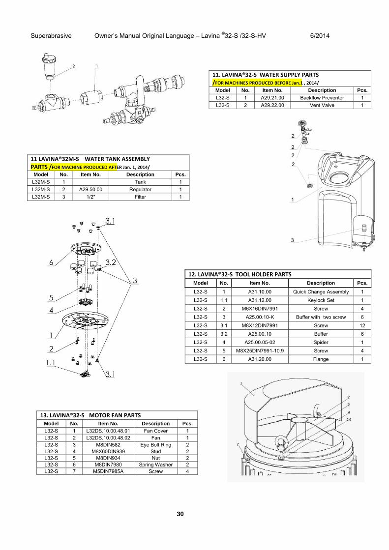
11. LAVINA®32‐S WATER SUPPLY PARTS/FOR MACHINES PRODUCED BEFORE Jan.1 , 2014/
Model No. Item No. Description Pcs.
L32-S 1 A29.21.00 Backflow Preventer 1
L32-S 2 A29.22.00 Vent Valve 1
13. LAVINA®32‐S MOTOR FAN PARTSModel No. Item No. Description Pcs.
L32-S 1 L32DS.10.00.48.01 Fan Cover 1 L32-S 2 L32DS.10.00.48.02 Fan 1 L32-S 3 M8DIN582 Eye Bolt Ring 2 L32-S 4 M8X60DIN939 Stud 2 L32-S 5 M8DIN934 Nut 2 L32-S 6 M8DIN7980 Spring Washer 2 L32-S 7 M5DIN7985A Screw 4
11 LAVINA®32M‐S WATER TANK ASSEMBLY PARTS /FOR MACHINE PRODUCED AFTER Jan. 1, 2014/
Model No. Item No. Description Pcs.
L32M-S 1 Tank 1
L32M-S 2 A29.50.00 Regulator 1
L32M-S 3 1/2" Filter 1
12. LAVINA®32‐S TOOL HOLDER PARTS
Model No. Item No. Description Pcs.
L32-S 1 A31.10.00 Quick Change Assembly 1
L32-S 1.1 A31.12.00 Keylock Set 1
L32-S 2 M6X16DIN7991 Screw 4
L32-S 3 A25.00.10-K Buffer with two screw 6
L32-S 3.1 M8X12DIN7991 Screw 12
L32-S 3.2 A25.00.10 Buffer 6
L32-S 4 A25.00.05-02 Spider 1
L32-S 5 M8X25DIN7991-10.9 Screw 4
L32-S 6 A31.20.00 Flange 1
Superabrasive Owner’s Manual Original Language – Lavina ®32-S /32-S-HV 6/2014
31
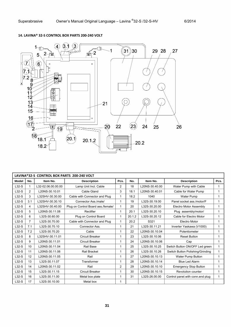
14. LAVINA® 32‐S CONTROL BOX PARTS 200‐240 VOLT
LAVINA®32‐S CONTROL BOX PARTS 200‐240 VOLT
Model No. Item No. Description Pcs. No. Item No. Description Pcs.
L32-S 1 L32-02.06.00.00.00 Lamp Unit Incl. Cable 2 18 L20NS-30.40.00 Water Pump with Cable 1
L32-S 2 L20NS-30.10.01 Cable Gland 3 18.1 L20NS-30.40.01 Cable for Water Pump 1
L32-S 3 L32SHV-30.30.00 Cable with Connector and Plug 1 18.2 1040 Water Pump 1
L32-S 3.1 L32SHV-30.30.10 Connector Ass./male/ 1 19 L32S-30.19.00 Panel socket ass./motor/F 1
L32-S 4 L32SHV-30.40.00 Plug on Control Board ass./female/ 1 20 L32S-30.20.00 Electro Motor Assembly 1
L32-S 5 L20NS-30.11.08 Rectifier 1 20.1 L32S-30.20.10 Plug assembly/motor/ 1
L32-S 6 L32S-30.60.00 Plug on Control Board 1 20.1.2 L32S-30.20.12 Cable for Electro Motor 1
L32-S 7 L32S-30.70.00 Cable with Connector and Plug 1 20.2 S321 Electro Motor 1
L32-S 7.1 L32S-30.70.10 Connector Ass. 1 21 L32S-30.11.21 Inverter Yaskawa (V1000) 1
L32-S 7.2 L32S-30.70.20 Cable 1 22 L20NS-30.10.04 Potentiometer 1
L32-S 8 L32SHV-30.11.01 Circuit Breaker 1 23 L32S-30.10.06 Reset Button 1
L32-S 9 L20NS-30.11.01 Circuit Breaker 1 24 L20NS-30.10.06 Cap 1
L32-S 10 L20NS-30.11.04 Rail Base 1 25 L32S-30.10.25 Switch Button ON/OFF Led green 1
L32-S 11 L20NS-30.11.06 Rail Bracket 1 26 L32S-30.10.26 Switch Button Polishing/Grinding 1
L32-S 12 L20NS-30.11.05 Rail 1 27 L20NS-30.10.13 Water Pump Button 1
L32-S 13 L32S-30.11.07 Transformer 1 28 L20NS-30.10.14 Blue Led Alarm 1
L32-S 14 L20NS-30.11.02 Rail 2 29 L20NS-30.10.10 Emergency Stop Button 1
L32-S 15 L32S-30.11.15 Circuit Breaker 1 30 L20NS-30.10.15 Revolution counter 1
L32-S 16 L32S-30.11.00 Metal box plate 1 31 L32S-26.00.00 Control panel.with conn.end plug 1
L32-S 17 L32S-30.10.00 Metal box 1
Superabrasive Owner’s Manual Original Language – Lavina ®32-S /32-S-HV 6/2014
32
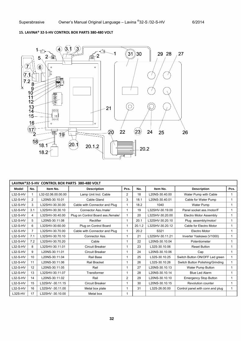
15. LAVINA® 32‐S‐HV CONTROL BOX PARTS 380‐480 VOLT
LAVINA®32‐S‐HV CONTROL BOX PARTS 380‐480 VOLT
Model No. Item No. Description Pcs. No. Item No. Description Pcs.
L32-S-HV 1 L32-02.06.00.00.00 Lamp Unit Incl. Cable 2 18 L20NS-30.40.00 Water Pump with Cable 1
L32-S-HV 2 L20NS-30.10.01 Cable Gland 3 18.1 L20NS-30.40.01 Cable for Water Pump 1
L32-S-HV 3 L32SHV-30.30.00 Cable with Connector and Plug 1 18.2 1040 Water Pump 1
L32-S-HV 3.1 L32SHV-30.30.10 Connector Ass./male/ 1 19 L32SHV-30.19.00 Panel socket ass./motor/F 1
L32-S-HV 4 L32SHV-30.40.00 Plug on Control Board ass./female/ 1 20 L32SHV-30.20.00 Electro Motor Assembly 1
L32-S-HV 5 L20NS-30.11.08 Rectifier 1 20.1 L32SHV-30.20.10 Plug assembly/motor/ 1
L32-S-HV 6 L32SHV-30.60.00 Plug on Control Board 1 20.1.2 L32SHV-30.20.12 Cable for Electro Motor 1
L32-S-HV 7 L32SHV-30.70.00 Cable with Connector and Plug 1 20.2 S321 Electro Motor 1
L32-S-HV 7.1 L32SHV-30.70.10 Connector Ass. 1 21 L32SHV-30.11.21 Inverter Yaskawa (V1000) 1
L32-S-HV 7.2 L32SHV-30.70.20 Cable 1 22 L20NS-30.10.04 Potentiometer 1
L32-S-HV 8 L32SHV-30.11.01 Circuit Breaker 1 23 L32S-30.10.06 Reset Button 1
L32-S-HV 9 L20NS-30.11.01 Circuit Breaker 1 24 L20NS-30.10.06 Cap 1
L32-S-HV 10 L20NS-30.11.04 Rail Base 1 25 L32S-30.10.25 Switch Button ON/OFF Led green 1
L32-S-HV 11 L20NS-30.11.06 Rail Bracket 1 26 L32S-30.10.26 Switch Button Polishing/Grinding 1
L32-S-HV 12 L20NS-30.11.05 Rail 1 27 L20NS-30.10.13 Water Pump Button 1
L32-S-HV 13 L32SHV-30.11.07 Transformer 1 28 L20NS-30.10.14 Blue Led Alarm 1
L32-S-HV 14 L20NS-30.11.02 Rail 2 29 L20NS-30.10.10 Emergency Stop Button 1
L32-S-HV 15 L32SHV -30.11.15 Circuit Breaker 1 30 L20NS-30.10.15 Revolution counter 1
L32-S-HV 16 L32SHV -30.11.00 Metal box plate 1 31 L32S-26.00.00 Control panel.with conn.end plug 1
L32S-HV 17 L32SHV -30.10.00 Metal box 1