Embed Size (px)
Citation preview
LaunchpadP1.1 attached to touch screen topP1.2 attached to touch screen right
But…
P1.1 and P1.2 attached to J3
Multivibrators and wave shaping circuits
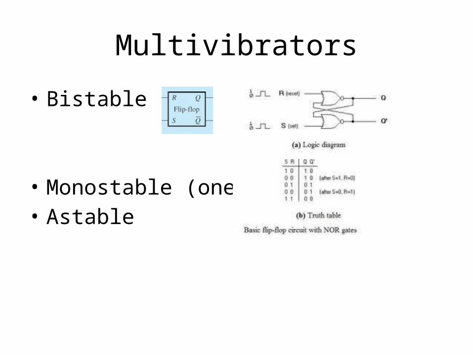
Multivibrators
• Bistable
• Monostable (one shot)• Astable
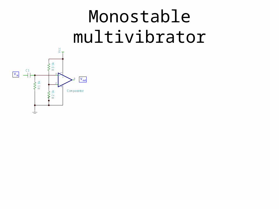
Monostable multivibrator
Vcc
C1
R1
1k -
+ +3
2
6
74
Comparator
R2
1kR
3 1k
V in
Vout
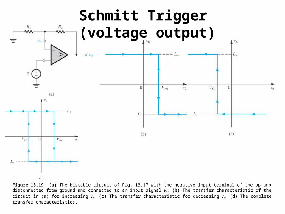
Figure 13.19 (a) The bistable circuit of Fig. 13.17 with the negative input terminal of the op amp disconnected from ground and connected to an input signal vI. (b) The transfer characteristic of the circuit in (a) for increasing vI. (c) The transfer characteristic for decreasing vI. (d) The complete transfer characteristics.
Schmitt Trigger (voltage output)
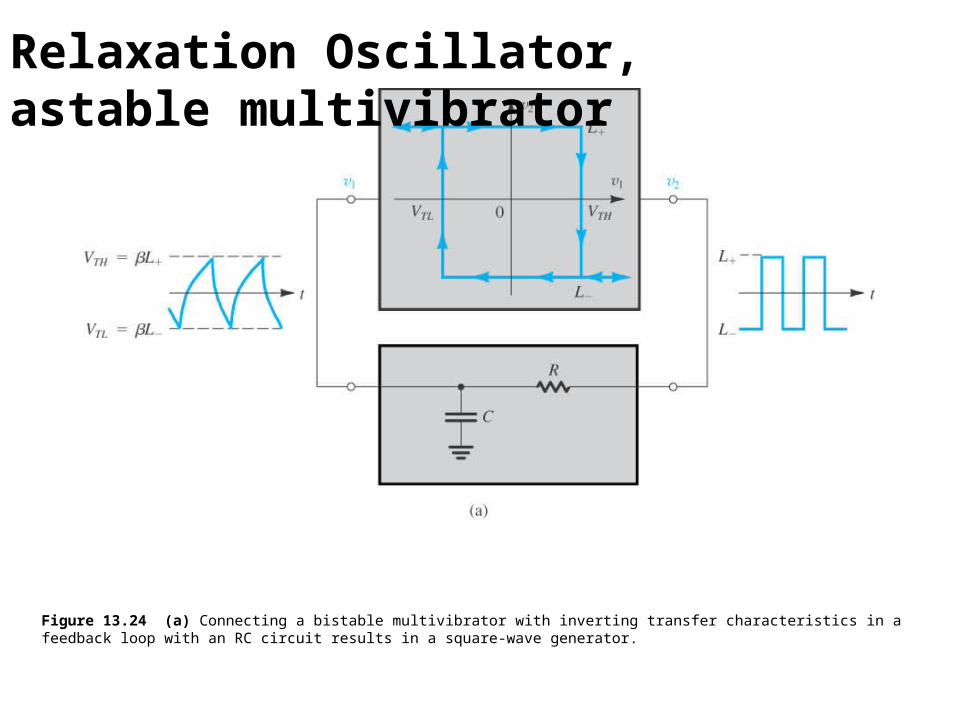
Figure 13.24 (a) Connecting a bistable multivibrator with inverting transfer characteristics in a feedback loop with an RC circuit results in a square-wave generator.
Relaxation Oscillator, astable multivibrator
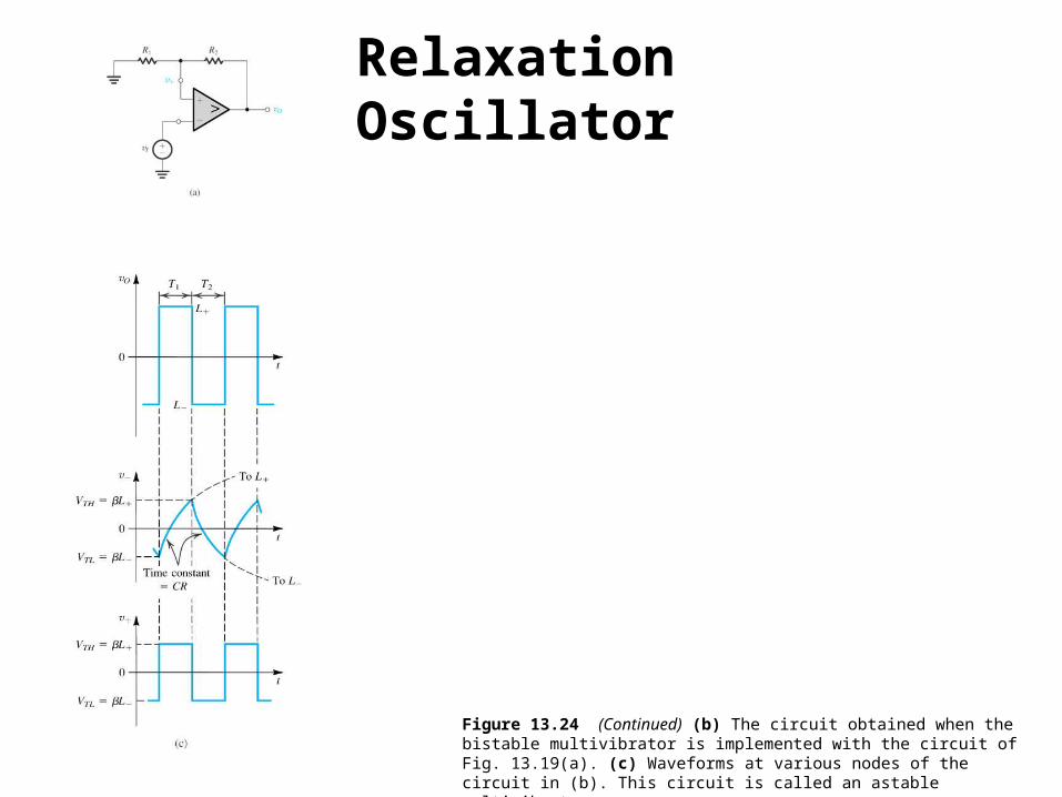
Figure 13.24 (Continued) (b) The circuit obtained when the bistable multivibrator is implemented with the circuit of Fig. 13.19(a). (c) Waveforms at various nodes of the circuit in (b). This circuit is called an astable multivibrator.
Relaxation Oscillator
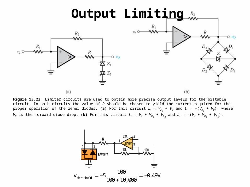
Figure 13.23 Limiter circuits are used to obtain more precise output levels for the bistable circuit. In both circuits the value of R should be chosen to yield the current required for the proper operation of the zener diodes. (a) For this circuit L+ = VZ1
+ VD and L– = –(VZ2 + VD), where VD is
the forward diode drop. (b) For this circuit L+ = VZ + VD1 + VD2
and L– = –(VZ + VD3 + VD4
).
1005 0 49100 10 000thresholdv . V
,
Output Limiting
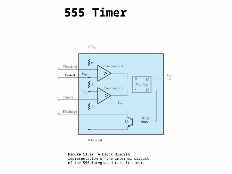
Figure 13.27 A block diagram representation of the internal circuit of the 555 integrated-circuit timer.
555 Timer
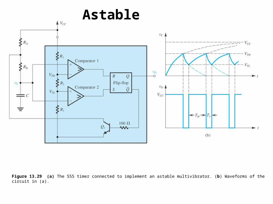
Figure 13.29 (a) The 555 timer connected to implement an astable multivibrator. (b) Waveforms of the circuit in (a).
Astable
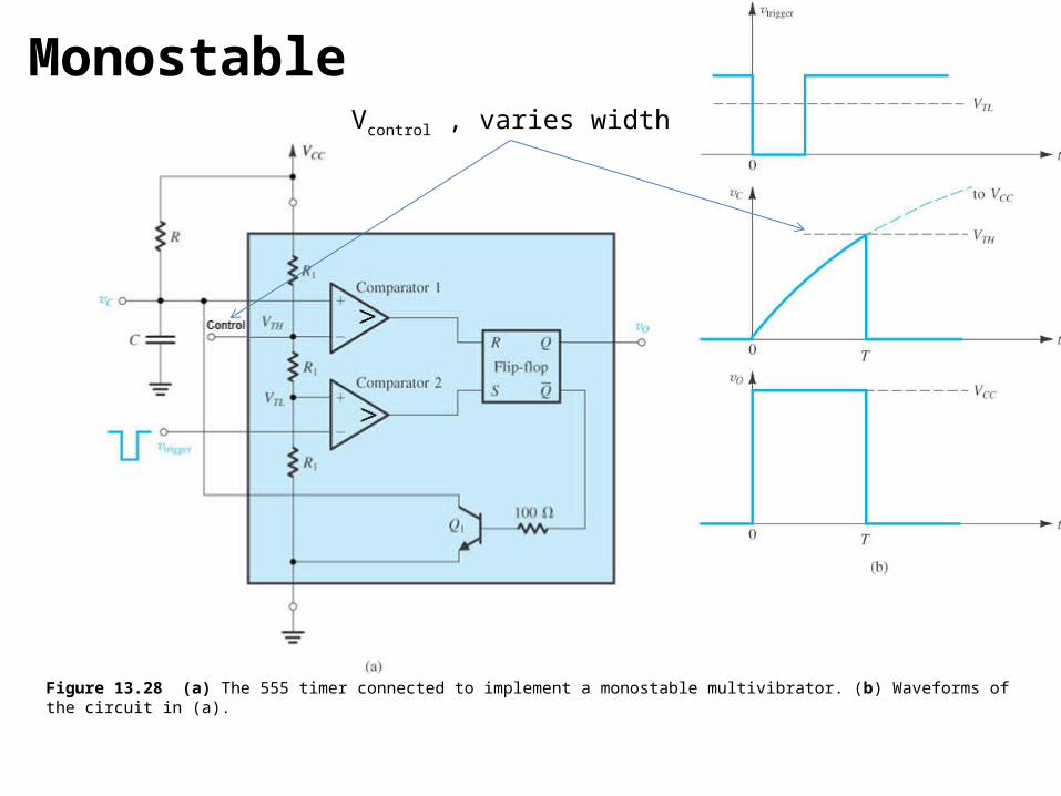
Figure 13.28 (a) The 555 timer connected to implement a monostable multivibrator. (b) Waveforms of the circuit in (a).
Vcontrol , varies width
Monostable
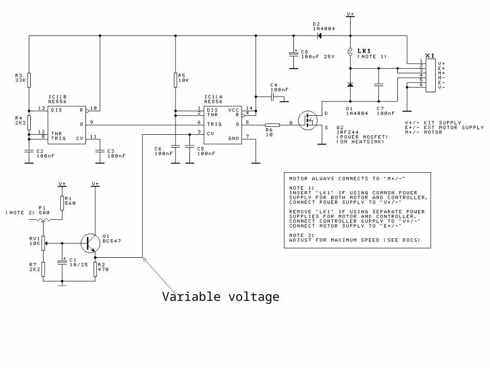
Variable voltage
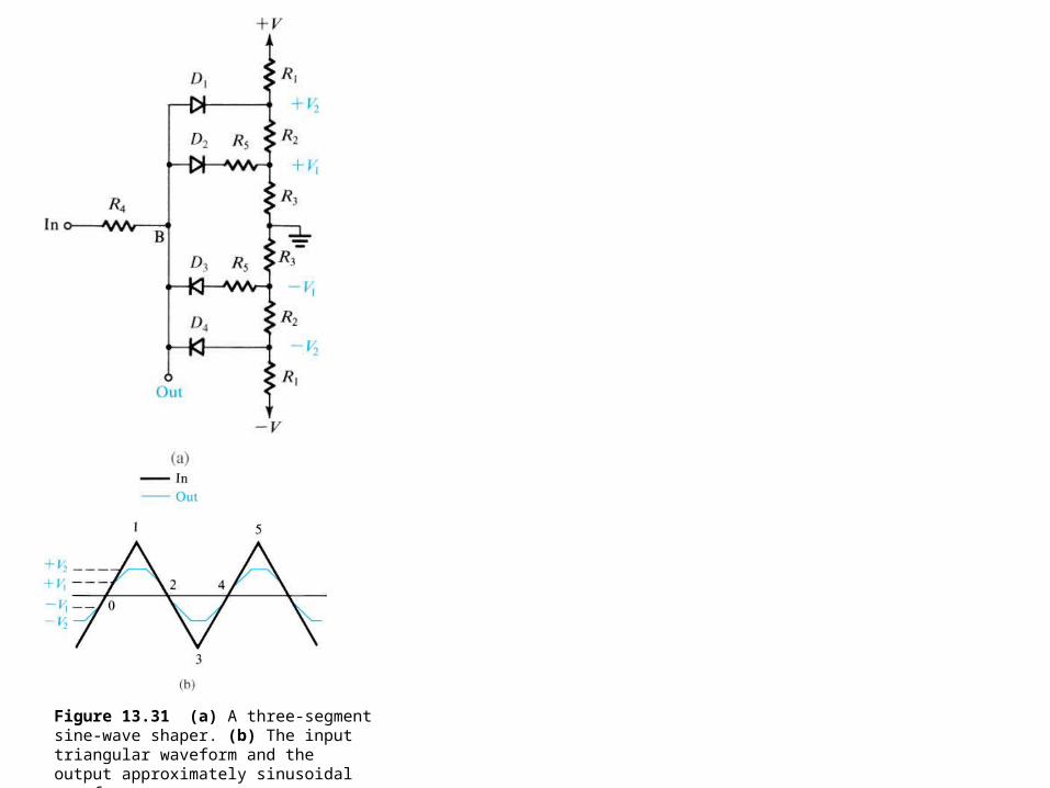
Figure 13.31 (a) A three-segment sine-wave shaper. (b) The input triangular waveform and the output approximately sinusoidal waveform.