Embed Size (px)
Citation preview

Latex 3000 Printer Series
Site Preparation Guide

© 2015 HP Development Company, L.P.
2
Legal notices
The information contained herein is subject tochange without notice.
The only warranties for HP Products andservices are set forth in the express warrantystatement accompanying such products andservices. Nothing herein should be construedas constituting an additional warranty. HP shallnot be liable for technical or editorial errors oromissions contained herein.
Table of contents
1 Introduction .................................................................................................................................................. 1
System configuration ............................................................................................................................................. 1
Documentation ...................................................................................................................................................... 1
Site preparation overview ..................................................................................................................................... 1
Customer responsibility ......................................................................................................................................... 2
2 Site preparation ............................................................................................................................................ 4
Planning for printer installation ............................................................................................................................ 4
Installation time schedule ..................................................................................................................................... 4
System operation requirements ............................................................................................................................ 5
Air supply requirements (pneumatic spindle) ..................................................................................................... 11
Room and spacial requirements .......................................................................................................................... 11
Designing the print production area ................................................................................................................... 14
Computer and networking requirements ............................................................................................................ 16
3 Shipment arrival preparation ....................................................................................................................... 20
Unloading area ..................................................................................................................................................... 20
Route from unloading site to installation site .................................................................................................... 20
Shipment items .................................................................................................................................................... 20
Tools and manpower required for installation .................................................................................................... 21
Moving equipment ............................................................................................................................................... 21
Waste disposal ..................................................................................................................................................... 24
ENWW iii

iv ENWW
1 Introduction
System configurationYour printer is supplied almost fully assembled and ready for the simple installation procedures described indetail in the installation guide. It comes complete with printheads and a printhead cleaner roll.
DocumentationThe following manuals are provided with your printer, and can also be downloaded fromhttp://www.hp.com/go/Latex3000/manuals/, http://www.hp.com/go/Latex3100/manuals/ andhttp://www.hp.com/go/Latex3500/manuals/.
● Introductory information
● Limited warranty
● Legal information
● Site preparation guide
● Site preparation checklist
● Installation guide
● User's guide
Site preparation overviewThis guide should assist in the following planning considerations:
● Modifications to the installation area
● Site accessibility
● Emergency exits
● Planning the print production area
● Mechanical, electrical and environmental specifications
● Computer and network connectivity
● Contracting a specialist mover with a forklift and/or suitable moving equipment
● Contracting an electrician
All information in this guide is provided on the assumption that installation planners and personnel arefamiliar with:
ENWW System configuration 1
● Architectural and planning requirements
● Applicable laws, regulations and standards
NOTE: It is important to read the information provided in this guide thoroughly and ensure completecompliance with all installation and operation prerequisites, safety procedures, warnings, cautions, and localregulations.
Customer responsibilityPlanning the site and printer environment
You are responsible for all preparations of the physical site, and you must complete the following tasks:
● Prepare the site for unloading. See Unloading area on page 20.
● Make sure the route from the unloading site to the installation site meets specifications. See Route fromunloading site to installation site on page 20.
● Make sure you have the necessary equipment to handle the printer, as well as a specialist mover who isfamiliar with your site and the information provided in this guide. See Moving equipment on page 21.
● Meet the requirements for second floor installations (if necessary). See Above ground floor installationon page 23.
● Configure the building's electrical system used to power the printer to meet the printer's requirementsand the Electrical Code requirements of the local jurisdiction of the country where the equipment isinstalled. A qualified electrician is required to power up the printer on the day of installation. SeeElectrical configuration on page 5.
● Provide an adequate air supply for the pneumatic spindles. See Air supply requirements (pneumaticspindle) on page 11.
● Meet temperature and humidity requirements and ensure proper ventilation for the printer. SeeVentilation and air conditioning on page 12 and Temperature and humidity on page 11.
● Supply all necessary emergency equipment. See Safety installations on page 14.
RIP installationIf you have bought HP RIP software for your printer:
● You must ensure that a computer is available on which to install the RIP.
● For full functionality, you are recommended to ensure that the computer is connected to the Internet.
● You must ensure that the HP RIP software has arrived by the agreed date of printer installation.
If you have bought non-HP RIP software for your printer:
NOTE: This guide does not provide information about your RIP solution.
● You must install the RIP on a suitable computer and ensure that it is fully functional by the agreed dateof printer installation.
● For full functionality, you are recommended to ensure that the computer is connected to the Internet.
● You must ensure that a RIP specialist and a network specialist are present on the agreed date of printerinstallation.
2 Chapter 1 Introduction ENWW
NetworkingYou are responsible for all networking requirements, and you must complete the following tasks:
NOTE: In order to perform remote support, the printer must have access to the internet using the LANconnection.
● Have an adequate network ready for the day of installation. See Computer and networking requirementson page 16.
● Provide a CAT-6 LAN cable to connect the printer to your LAN on the day of installation.
Printing supplies for testing and trainingYou are responsible for providing the following printing supplies:
● Seven ink cartridges, for the six colors and the optimizer (no cartridges are supplied with the printer)
NOTE: In addition, you are recommended to have a second set of seven ink cartridges, four printheads,and one HP 881 Latex Cleaning Roll, in case any replacements are needed.
● Compressed air supply for the pneumatic spindle. See Air pressure supply on page 11.
● Some rolls of substrate for printing; preferably the substrate type that you plan to use most in future
● To test dual-roll printing, two rolls of max 1524 mm (63 in), max weight per roll 80 kg.
Return the site preparation checklistThe checklist must be completed and returned to your reseller or service representative a minimum of twoweeks before the day of installation.
NOTE: Any delays during installation that are caused by an unprepared site will be charged to the customer.Take care that your site is properly prepared to ensure a smooth and easy installation.
Recycle the disposable ink bag and HP 881 Latex Cleaning RollThese items require disposal according to local regulations. For further information, please refer to the MSDSdocument about your printer's ink, available from http://www.hp.com/hpinfo/community/environment/productinfo/psis_inkjet.htm.
Recycle the printheadsThe printheads require disposal according to local regulations. For further information, please refer to theMSDS document about your printer's ink, available from http://www.hp.com/hpinfo/community/environment/productinfo/psis_inkjet.htm. Within some countries covered by the ‘HP Planet Partners Returns’, HP isoffering a recycling program. For full details of this program, please visit http://www.hp.com/recycle/.
Dispose of liquid wasteDispose of liquid waste in compliance with all applicable federal, state, and local regulations.
ENWW Customer responsibility 3
2 Site preparation
Planning for printer installationThis chapter covers the main topics related to efficient planning and preparation of the site. Take intoconsideration any structural modifications required and the time required for submission and approval ofplans to the relevant local authorities. Secure temporary storage for the shipping crate prior to equipmentinstallation may also be necessary.
CAUTION: All cables connected to the printer should be contained within suitable conduits; these may beoverhead or channeled into the floor, as appropriate. Tripping over loose wires or cables can cause personalinjury and/or damage to the equipment.
Installation time scheduleThe best method to ensure a smooth and trouble-free installation process is proper site preparation. Thefollowing time schedule estimate is based on the assumption that all system components have beendelivered in proper working order and all site preparation and planning requirements have been met andcompleted, in accordance with the specifications provided in this guide. The installation process is divided intotwo phases:
Table 2-1 Installation time schedule
Time to completion
Installation and system configuration 2 full working days
Operation and maintenance training 2.5 full working days
Although the optimal time schedule requires approximately 4 working days, it may be necessary to scheduleadditional time for either phase. Please plan ahead for any special circumstances that may occur during theinstallation process, and do not plan for production during installation and training.
If the RIP software is bought from HP, the training will cover the normal use of the RIP. The following aspectsof RIP usage will be covered:
HP Scitex ONYX Thrive 211 RIP
● RIP-Queue
● Configure the printer (Quickset, Device output, Media, Page size, Properties)
● Main items of the Job Editor (Printer and media selection, Preview and size, Tiling setup, Colorcorrection, Print)
The Media Manager will not be covered.
4 Chapter 2 Site preparation ENWW

HP Scitex CALDERA GRAND RIP V10
● Server Administration (Server, Configure, Connection)
● GrandRIP+ (Main, Tool, Settings)
● Spooler
● Image Work Directory (Image positioning and scale setting on the page, and so on)
Profile creation will not be covered.
System operation requirementsElectrical configuration
NOTE: An electrician is required for the setup and configuration of the building electrical system used topower the printer and also for printer installation. Make sure that your electrician is appropriately certifiedaccording to local regulations and supplied with all the information regarding the electrical configuration.
The HP Internal Print Server can be powered with a single-phase line that can be used with an UninterruptiblePower Supply (UPS). The UPS must be rated to meet the power requirements of the printer, and should be inaccordance with the wiring standards of the country of installation.
The printer requires the following electrical components to be supplied and installed by the customer,according to the Electrical Code requirements of the local jurisdiction of the country of installation.
1. Uninterruptible Power Supply (UPS) for single-phase control line (optional)
NOTE: The HP Internal Print Server power can be obtained by making a connection inside the electricalcabinet.
2. Power Distribution Unit (PDU) including single-phase branch circuit breaker (optional)
3. Power Distribution Unit (PDU) including three-phase or two-phase branch circuit breaker depending onthe power configuration
ENWW System operation requirements 5
NOTE: Remember that you are required to follow the local laws, regulations, and standards that apply tothe electrical installation of your printer.
NOTE: The printer is not supplied with any power cable.
Power distribution unit (PDU)
The PDU must be rated to meet the power requirements of the printer, and should be in accordance with theElectrical Code requirements of the local jurisdiction of the country where the equipment is installed.
Power specifications
Configuration 1: 380–415 V line-to-line three-phase configuration
Table 2-2 Three-phase specifications
Number of power wires 5 (L1/L2/L3/N/PE)
Input voltage (line to line) 380–415 V~ (±10%)
Input frequency 50/60 Hz
Power consumption (typical) 9–11 kW
Maximum load current (per phase) 35 A
Table 2-3 Branch circuit breaker specifications
Three-phase 4 poles, 40/50 A
Table 2-4 AC three-phase power cable specifications
Configuration 5 wires, L1/L2/L3/N/PE
Wire Strained Cu minimum, 10 mm² or 8 AWG
Terminals Lines, ferrule terminals, PE, M8 ring terminal
External diameter range 22.0–33.0 mm
Configuration 2: 200–240 V line-to-line three-phase configuration
Table 2-5 Three-phase specifications
Number of power wires) 4 (L1/L2/L3/PE)
Input voltage (line to line) 200–240V (±10%)
Input frequency 50/60 Hz
Power consumption (typical) 9–11 kW
Maximum load current (per phase) 56 A
Table 2-6 Branch circuit breaker specifications
Three-phase 3 poles, 63/70 A
6 Chapter 2 Site preparation ENWW
Table 2-7 AC three-phase power cable specifications
Configuration 4 wires, L1/L2/L3/PE
Wire Strained Cu minimum, 10 mm² or 6 AWG
Terminals Lines, ferrule terminals, PE, M8 ring terminal
External diameter range 22.0–33.0 mm
Configuration 3: 380–415 V line-to-line three-phase configuration with single-phase control
Table 2-8 Specifications
Three-phase line Single-phase control
Number of power wires 5 (L1/L2/L3/N/PE) 3 (L/N/PE)
Input voltage (line to line) 380–415 V~ (±10%) 100–240 V (±10%)
Input frequency 50/60 Hz 50/60 Hz
Power consumption (typical) 9–11 kW 0.5 kW
Maximum load current (per phase) 35 A 10 A
Table 2-9 Branch circuit breaker specifications
Three-phase 4 poles, 40/50 A
Two-phase control 2 poles, 15/16/20 A
Table 2-10 AC Power cable specifications
Three-phase line Single-phase line
Configuration 5 wires, L1/L2/L3/N/PE 3 wires, L/N/PE
Wire Strained Cu minimum, 10 mm² or 8 AWG Strained Cu minimum, 1.5 mm² or 16 AWG
Terminals Lines, ferrule terminals, PE, M8 ringterminal
Lines, ferrule terminals, PE, M4 ringterminal
External diameter range 22.0–33.0 mm 5.0–11.0 mm
Configuration 4: 200–240 V line-to-line three-phase configuration with single-phase control
Table 2-11 Specifications
Three-phase line Single-phase control
Number of power wires 4 (L1/L2/L3/PE) 3 (L/N/PE)
Input voltage (line to line) 200–240 V (±10%) 100–240 V (±10%)
Input frequency 50/60 Hz 50/60 Hz
Power consumption (typical) 9–11 kW 0.5 kW
Maximum load current (per phase) 56 A 10 A
ENWW System operation requirements 7
Table 2-12 Branch circuit breaker specifications
Three-phase 3 poles, 63/70 A
Two-phase control 2 poles, 15/16/20 A
Table 2-13 AC Power cable specifications
Three-phase line Single-phase line
Configuration 4 wires, L1/L2/L3/PE 3 wires, L/N/PE
Wire Strained Cu minimum, 10 mm² or 6 AWG Strained Cu minimum, 2.5 mm² or 16 AWG
Terminals Lines, ferrule terminals, PE, M8 ringterminal
Lines, ferrule terminals, PE, M4 ringterminal
External diameter range 22.0–33.0 mm 5.0–11.0 mm
Configuration 5: 240 V line-to-line single-phase configuration
NOTE: Three-phase power provides a more efficient means of supplying large electrical loads than single-phase power, which is common in offices and homes. Connect single-phase if no three-phase power isavailable.
Table 2-14 Single-phase specifications
Number of power wires 3 (L1/L2/PE)
Input voltage (line to line) 240 V (±10%)
Input frequency 50/60 Hz
Power consumption (typical) 9–11 kW
Maximum load current (per phase) 72 A
Table 2-15 Branch circuit breaker specifications
Two-phase 2 poles, 90 A
Table 2-16 AC single-phase power cable specifications
Configuration 3 wires, L1/L2/PE
Wire Strained Cu minimum, 4 AWG
Terminals Lines, ferrule terminals, PE, M8 ring terminal
External diameter range 22.0–33.0 mm
Configuration 6: 240 V line-to-line single-phase configuration with single-phase control
NOTE: Three-phase power provides a more efficient means of supplying large electrical loads than single-phase power, which is common in offices and homes. Connect single-phase if no three-phase power isavailable.
8 Chapter 2 Site preparation ENWW
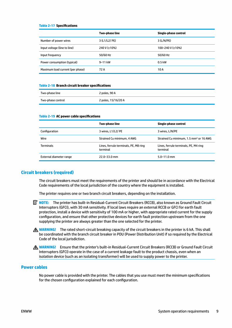
Table 2-17 Specifications
Two-phase line Single-phase control
Number of power wires 3 (L1/L2/ PE) 3 (L/N/PE)
Input voltage (line to line) 240 V (±10%) 100–240 V (±10%)
Input frequency 50/60 Hz 50/60 Hz
Power consumption (typical) 9–11 kW 0.5 kW
Maximum load current (per phase) 72 A 10 A
Table 2-18 Branch circuit breaker specifications
Two-phase line 2 poles, 90 A
Two-phase control 2 poles, 15/16/20 A
Table 2-19 AC power cable specifications
Two-phase line Single-phase control
Configuration 3 wires, L1/L2/ PE 3 wires, L/N/PE
Wire Strained Cu minimum, 4 AWG Strained Cu minimum, 1.5 mm² or 16 AWG
Terminals Lines, ferrule terminals, PE, M8 ringterminal
Lines, ferrule terminals, PE, M4 ringterminal
External diameter range 22.0–33.0 mm 5.0–11.0 mm
Circuit breakers (required)
The circuit breakers must meet the requirements of the printer and should be in accordance with the ElectricalCode requirements of the local jurisdiction of the country where the equipment is installed.
The printer requires one or two branch circuit breakers, depending on the installation.
NOTE: The printer has built-in Residual-Current Circuit Breakers (RCCB), also known as Ground Fault CircuitInterrupters (GFCI), with 30 mA sensitivity. If local laws require an external RCCB or GFCI for earth faultprotection, install a device with sensitivity of 100 mA or higher, with appropriate rated current for the supplyconfiguration, and ensure that other protective devices for earth fault protection upstream from the onesupplying the printer are always greater than the one selected for the printer.
WARNING! The rated short-circuit breaking capacity of the circuit breakers in the printer is 6 kA. This shallbe coordinated with the branch circuit breaker in PDU (Power Distribution Unit) if so required by the ElectricalCode of the local jurisdiction.
WARNING! Ensure that the printer's built-in Residual-Current Circuit Breakers (RCCB) or Ground Fault CircuitInterrupters (GFCI) operate in the case of a current leakage fault to the product chassis, even when anisolation device (such as an isolating transformer) will be used to supply power to the printer.
Power cables
No power cable is provided with the printer. The cables that you use must meet the minimum specificationsfor the chosen configuration explained for each configuration.
ENWW System operation requirements 9

PE connections for mains power should be made through an M8 stub.
The power cable for PC power can be routed from above the right of the top cover; it can be routed from theceiling.
Powerline disturbancesReliable operation of your printer depends on the availability of relatively noise-free AC power.
● In order to ensure optimum performance and reliability, your printer should be protected fromvariations in line voltage, which are common to production printing environments. Lighting, line faults,or the power switching commonly found in machinery in factory environments can generate linetransients that far exceed the peak value of the applied voltage. If not reduced, these micro-secondpulses can disrupt system operation.
● If the power line supplying the installation site is a public low voltage line shared with other users, thepower line impedance Zmax must be less than 93 mΩ, to comply with European standard EN/IEC61000-3-12. If other users on the same power line report any flickering of incandescent light bulbs,contact your electricity supplier to verify that the power network has an impedance lower than the onespecified above.
● It is recommended to include overvoltage (OVP) and transient protection on the power supply to theprinter.
● All electrical noise generating equipment, like fans, fluorescent lighting, and air-conditioning systems,should be kept separate from the power source used for your printer.
GroundingThe printer must be connected to a good quality, dedicated ground line in order to avoid electrical risk. Pleasenote your obligation to comply with the National Electrotechnical Code (NEC) in the county of installation.
The following grounding tasks must be fulfilled to meet the site preparation requirements:
● Grounding wires should be insulated and at least equal in size to the phase conductors.
● Ground impedance must be less than 0.5 Ω.
● The installation of a single point and dedicated ground.
● Power stabilizer equipment that is supplied by three uninterrupted phase wires and one uninterruptedcopper ground wire from the main building service panel. These should run in the same conduit andshould be at least equal in size to the phase wires.
10 Chapter 2 Site preparation ENWW
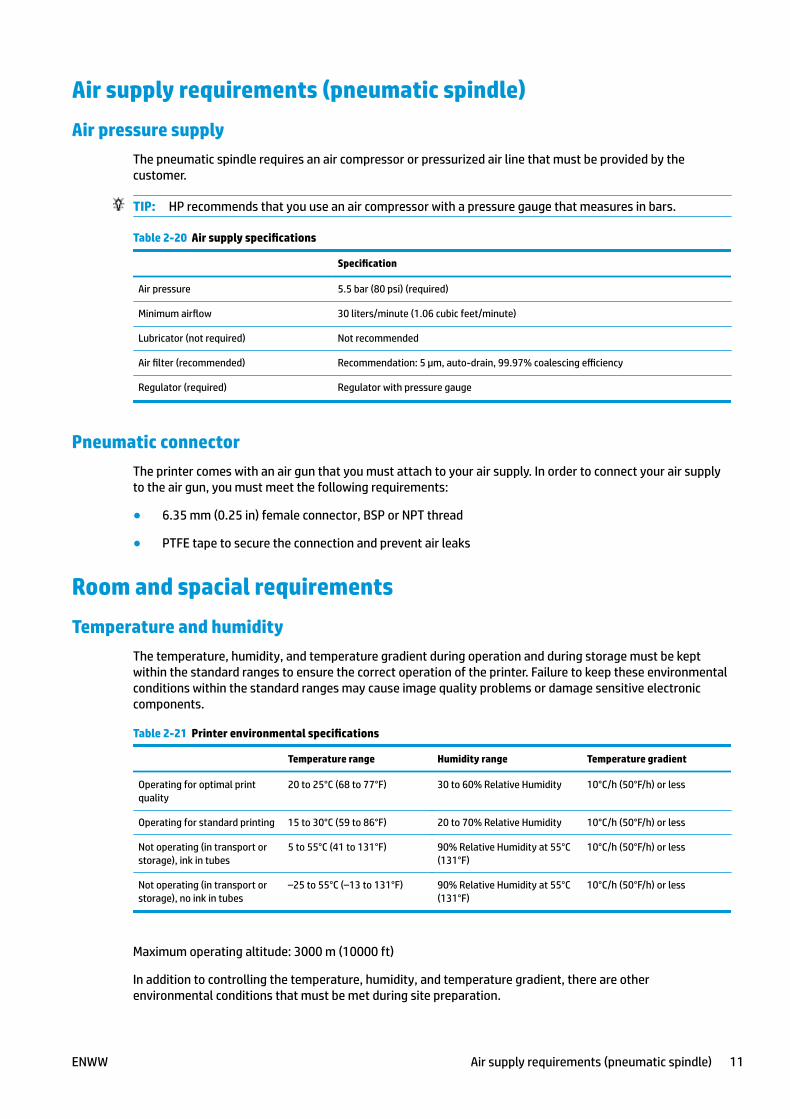
Air supply requirements (pneumatic spindle)Air pressure supply
The pneumatic spindle requires an air compressor or pressurized air line that must be provided by thecustomer.
TIP: HP recommends that you use an air compressor with a pressure gauge that measures in bars.
Table 2-20 Air supply specifications
Specification
Air pressure 5.5 bar (80 psi) (required)
Minimum airflow 30 liters/minute (1.06 cubic feet/minute)
Lubricator (not required) Not recommended
Air filter (recommended) Recommendation: 5 µm, auto-drain, 99.97% coalescing efficiency
Regulator (required) Regulator with pressure gauge
Pneumatic connectorThe printer comes with an air gun that you must attach to your air supply. In order to connect your air supplyto the air gun, you must meet the following requirements:
● 6.35 mm (0.25 in) female connector, BSP or NPT thread
● PTFE tape to secure the connection and prevent air leaks
Room and spacial requirementsTemperature and humidity
The temperature, humidity, and temperature gradient during operation and during storage must be keptwithin the standard ranges to ensure the correct operation of the printer. Failure to keep these environmentalconditions within the standard ranges may cause image quality problems or damage sensitive electroniccomponents.
Table 2-21 Printer environmental specifications
Temperature range Humidity range Temperature gradient
Operating for optimal printquality
20 to 25°C (68 to 77°F) 30 to 60% Relative Humidity 10°C/h (50°F/h) or less
Operating for standard printing 15 to 30°C (59 to 86°F) 20 to 70% Relative Humidity 10°C/h (50°F/h) or less
Not operating (in transport orstorage), ink in tubes
5 to 55°C (41 to 131°F) 90% Relative Humidity at 55°C(131°F)
10°C/h (50°F/h) or less
Not operating (in transport orstorage), no ink in tubes
–25 to 55°C (–13 to 131°F) 90% Relative Humidity at 55°C(131°F)
10°C/h (50°F/h) or less
Maximum operating altitude: 3000 m (10000 ft)
In addition to controlling the temperature, humidity, and temperature gradient, there are otherenvironmental conditions that must be met during site preparation.
ENWW Air supply requirements (pneumatic spindle) 11
● Do not install the printer where it will be exposed to direct sunlight or a strong light source.
● Do not install the printer in a dusty environment. Remove any accumulated dust before moving theprinter into the area.
Ventilation and air conditioningAs with all equipment installations, to maintain ambient comfort levels, air conditioning or ventilation in thework area should take into account that the printer produces heat. Typically, the printer's power dissipation is9-11 KW (31-38 KBTU/h).
Air conditioning and ventilation should meet with local environmental, health and safety (EHS) guidelines andregulations. Consult your usual air conditioning or EHS specialist for advice on the appropriate measures foryour location.
For a more prescriptive approach to adequate ventilation, you could refer to the ANSI/ASHRAE (AmericanSociety of Heating, Refrigerating and Air-Conditioning Engineers) 62.1-2007 Ventilation for Acceptable IndoorAir Quality. As an example, a minimum exhaust rate of 2.5 L/s.m² (0.5 cfm/ft²) of fresh make up air for “copy,printing rooms” is specified.
Special ventilation is not required to meet US OSHA requirements on occupational exposure to VOCs fromHP Latex inks. Special ventilation-equipment installation is at the discretion of the customer—no specific HPrecommendation is intended for special ventilation. Customers should consult state and local requirementsand regulations.
NOTE: The ventilation and air conditioning units should not blow air directly onto the printer.
NOTE: You are recommended to maintain a positive airflow in the print production room to help preventdust from entering the room.
NOTE: HP recommends a minimum of 10 ACH (air changes per hour) for a 80 m³ room.
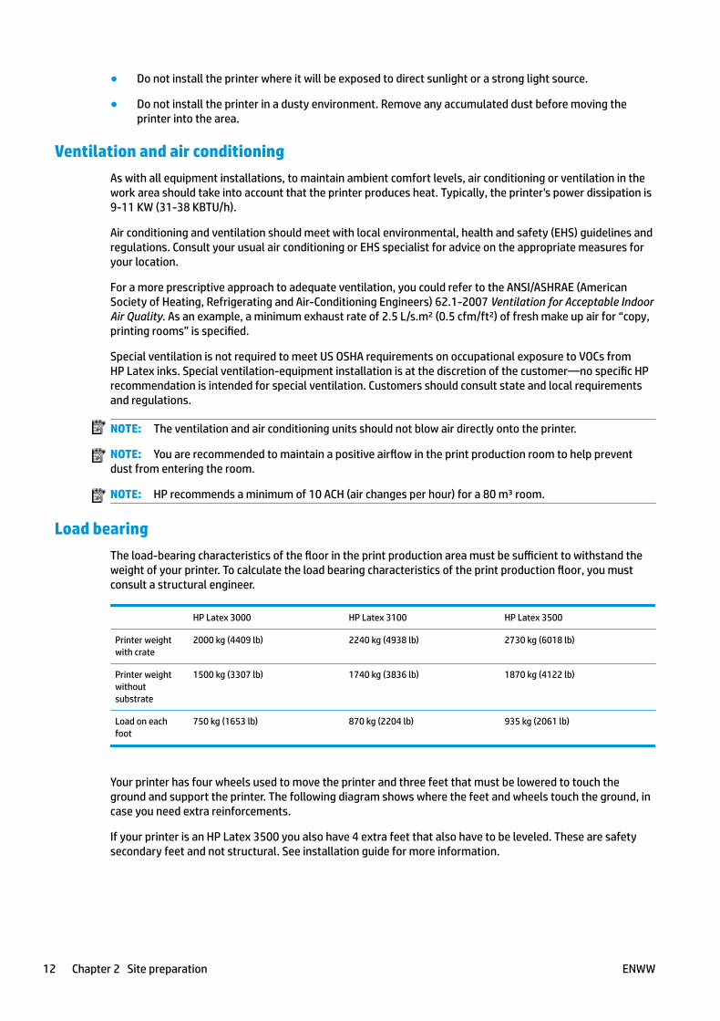
Load bearingThe load-bearing characteristics of the floor in the print production area must be sufficient to withstand theweight of your printer. To calculate the load bearing characteristics of the print production floor, you mustconsult a structural engineer.
HP Latex 3000 HP Latex 3100 HP Latex 3500
Printer weightwith crate
2000 kg (4409 lb) 2240 kg (4938 lb) 2730 kg (6018 lb)
Printer weightwithoutsubstrate
1500 kg (3307 lb) 1740 kg (3836 lb) 1870 kg (4122 lb)
Load on eachfoot
750 kg (1653 lb) 870 kg (2204 lb) 935 kg (2061 lb)
Your printer has four wheels used to move the printer and three feet that must be lowered to touch theground and support the printer. The following diagram shows where the feet and wheels touch the ground, incase you need extra reinforcements.
If your printer is an HP Latex 3500 you also have 4 extra feet that also have to be leveled. These are safetysecondary feet and not structural. See installation guide for more information.
12 Chapter 2 Site preparation ENWW
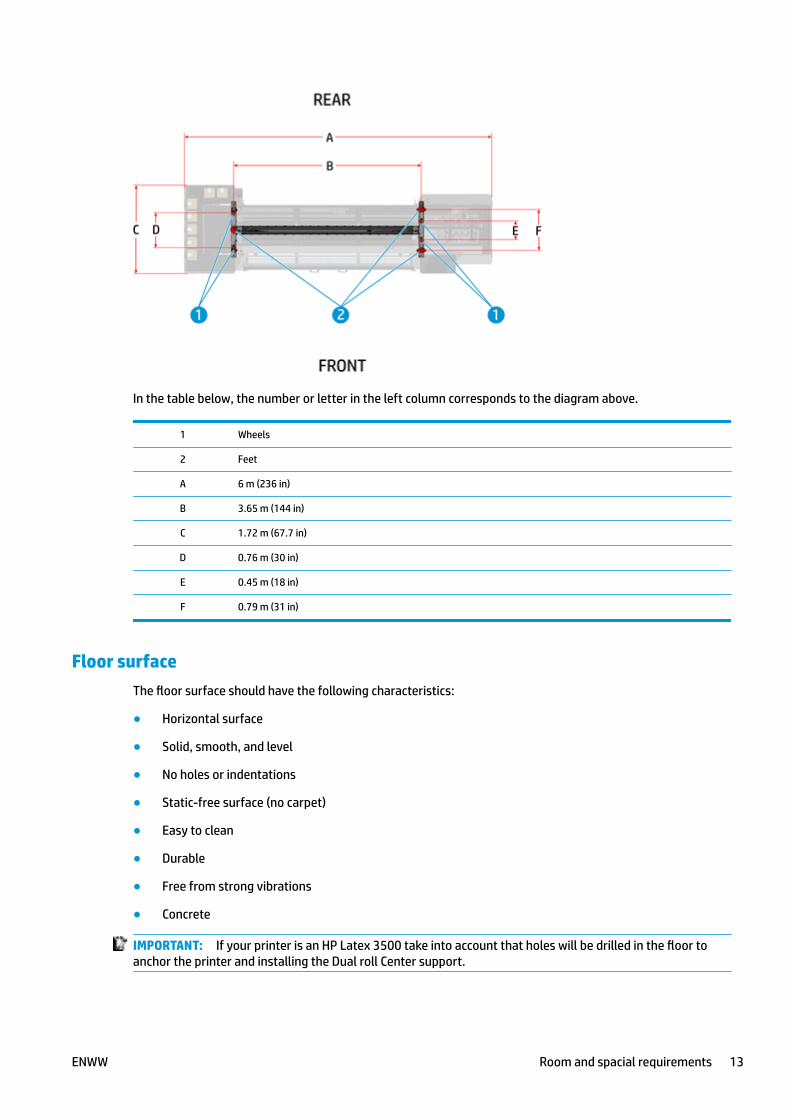
In the table below, the number or letter in the left column corresponds to the diagram above.
1 Wheels
2 Feet
A 6 m (236 in)
B 3.65 m (144 in)
C 1.72 m (67.7 in)
D 0.76 m (30 in)
E 0.45 m (18 in)
F 0.79 m (31 in)
Floor surfaceThe floor surface should have the following characteristics:
● Horizontal surface
● Solid, smooth, and level
● No holes or indentations
● Static-free surface (no carpet)
● Easy to clean
● Durable
● Free from strong vibrations
● Concrete
IMPORTANT: If your printer is an HP Latex 3500 take into account that holes will be drilled in the floor toanchor the printer and installing the Dual roll Center support.
ENWW Room and spacial requirements 13
LightingWhenever your printer is in operation, the print production area should be well lit to provide the operator withoptimal conditions for checking the color and alignment during print production. If there is not enoughnatural light, artificial lighting will be required.
Designing the print production areaSafety installations
Fire fighting equipment
You must provide two fire extinguishers for the site. Make sure the extinguishers are placed where they areeasily accessible in case of fire.
● A fire extinguisher certified for electrical fires must be in the print production area.
● A fire extinguisher must be placed in the substrate storage area, due to the large amount of solidcombustibles (substrates).
Emergency exits and first aid stations should also be considered.
Optimal room layoutYour printer requires enough space to perform the following tasks:
● Use the HP Internal Print Server
● Replace a substrate roll
● Service the printer or replace printer components
● Ensure the printer is well ventilated
Your printer has the following dimensions:
Table 2-22 Physical specifications
HP Latex 3000 HP Latex 3100/3500
Weight 1500 kg (3307 lb) 1740 Kg (3836 lb)/1870 Kg (4122 lb)
Width 5.98 m (235 in) 5.98 m (235 in)
Depth 1.72 m (67.7 in) 1.72 m (68 in)
Height 1.67 m (65.7 in) 1.87 m (74 in)
14 Chapter 2 Site preparation ENWW
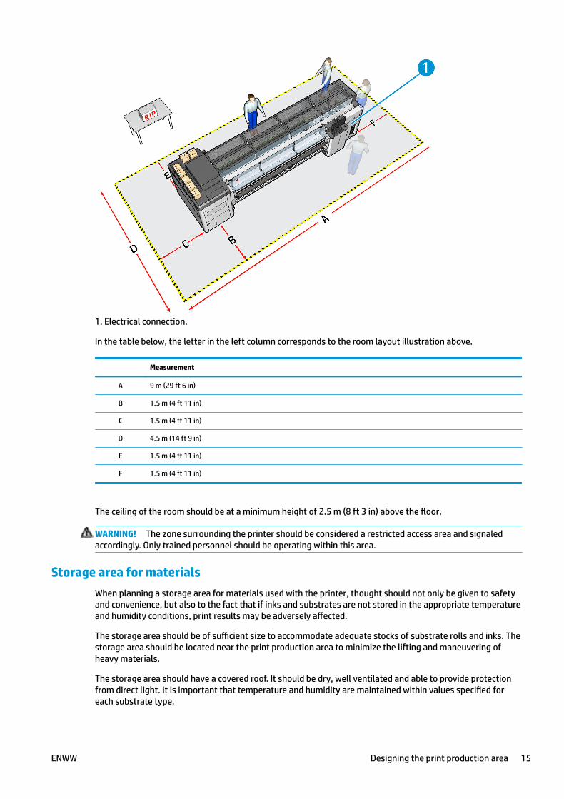
1. Electrical connection.
In the table below, the letter in the left column corresponds to the room layout illustration above.
Measurement
A 9 m (29 ft 6 in)
B 1.5 m (4 ft 11 in)
C 1.5 m (4 ft 11 in)
D 4.5 m (14 ft 9 in)
E 1.5 m (4 ft 11 in)
F 1.5 m (4 ft 11 in)
The ceiling of the room should be at a minimum height of 2.5 m (8 ft 3 in) above the floor.
WARNING! The zone surrounding the printer should be considered a restricted access area and signaledaccordingly. Only trained personnel should be operating within this area.
Storage area for materialsWhen planning a storage area for materials used with the printer, thought should not only be given to safetyand convenience, but also to the fact that if inks and substrates are not stored in the appropriate temperatureand humidity conditions, print results may be adversely affected.
The storage area should be of sufficient size to accommodate adequate stocks of substrate rolls and inks. Thestorage area should be located near the print production area to minimize the lifting and maneuvering ofheavy materials.
The storage area should have a covered roof. It should be dry, well ventilated and able to provide protectionfrom direct light. It is important that temperature and humidity are maintained within values specified foreach substrate type.
ENWW Designing the print production area 15
NOTE: Allow enough (environmentally controlled) space to store the printheads. This is indicated by thedirectional arrows on the printhead boxes.
Storage conditions for substrate rollsKeep substrate rolls in their sealed wrapping material while they are placed in storage.
Store substrate rolls vertically to avoid the migration of plasticizers in some materials.
Move substrates from the storage area to the print production area at least 24 hours before use, so that theycan reach the required moistness and operating temperature.
NOTE: HP substrate rolls have a 12 month warranty when the substrate rolls are stored under optimalconditions. The warranty term varies depending upon the material and the manufacturer.
Computer and networking requirementsRequirements
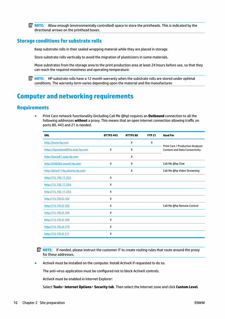
● Print Care network functionality (including Call Me @hp) requires an Outbound connection to all thefollowing addresses without a proxy. This means that an open internet connection allowing traffic onports 80, 443 and 21 is needed.
URL HTTPS 443 HTTPS 80 FTP 21 Used For
http://www.hp.com X XPrint Care / Production AnalyzerContent and Data Connectivityhttps://spcastweb01p.saas.hp.com X X
http://spcw01.saas.hp.com X
http://h50203.www5.hp.com X X Call Me @hp Chat
http://g5w2114g.atlanta.hp.com X Call Me @hp Video Streaming
http://15.192.17.253 X
http://15.192.17.254 X
http://15.192.17.255 X
http://15.193.0.102 X
http://15.193.0.103 X Call Me @hp Remote Control
http://15.193.0.104 X
http://15.193.0.169 X
http://15.193.0.170 X
http://15.193.0.171 X
NOTE: If needed, please instruct the customer IT to create routing rules that route around the proxyfor these addresses.
● ActiveX must be installed on the computer. Install ActiveX if requested to do so.
The anti-virus application must be configured not to block ActiveX controls.
ActiveX must be enabled in Internet Explorer:
Select Tools> Internet Options> Security tab. Then select the Internet zone and click Custom Level.
16 Chapter 2 Site preparation ENWW
Under ActiveX controls and plug-ins, enable:
◦ Allow previously unused ActiveX controls to run without prompt
◦ Automatic prompting for ActiveX controls
● A minimum upload speed of 256 bps is required.
HP provides the following system components:
HP provided components
● HP Internal Print Server
◦ PC and power cord. PC LAN card connections: 2 ethernet ports, one for the e-box LAN cable toconnect the printer to the PC, and the other to connect to the network
◦ Monitor and power cord
◦ Keyboard
◦ Mouse
◦ Windows 7 Embedded
◦ HP Internal Print Server software
◦ HP Scitex Print Care software
◦ Symantec Antivirus
◦ Webcam
● 1-Gb Ethernet cables
Customer provided components
● Ethernet LAN (minimum 100 Mb/s, optimum 1 Gb/s) connection
● RIP station and software
● CAT-6 LAN cable long enough to connect the printer to the network
RIP requirementsThere are two RIPs offered by HP that may be used with the printer:
● HP Scitex ONYX Thrive 211 RIP: product number D9Z41A
● HP Scitex Caldera Grand RIP v10 Software: product number L5E74A
The software and hardware requirements of these RIPs are as follows.
HP Scitex ONYX Thrive 211 RIP (v 11.1.2)
● Main Workstation requirements:
◦ Operating System: Microsoft Windows 7 Professional operating system (SP1 or higher) Windows 8Professional
NOTE: 32-bit operating systems have a hardware limit of 4GB of RAM. It is recommended you use64-bit operating systems for high volume workflows.
◦ Processor: Intel Core i7 or Equivalent
ENWW Computer and networking requirements 17

◦ RAM: 4 GB/processing core
◦ Hard Drive
◦ Multiple Hard Drives
● 1 – Dedicated System Drive
● 1 – Dedicated Drive for ONYX Thrive (500+ GB Free Space)
◦ Network Connectivity: Gigabit ethernet for TCP/IP printers
NOTE: Firewall and antivirus must be disabled or configured to allow ONYX applications andprinter ports (515, 1947, 8889, 9100 and 10000). There may be other ports needed, please seedevice manufacturer for details.
◦ Monitor: 1280 × 1024 pixels, 16-bit color
◦ USB port for security key
◦ DVD-ROM drive
● Distributed Workstation requirements:
◦ Microsoft Windows 7 Professional operating system (SP1 or higher) Windows 8 Professional
NOTE: 32-bit operating systems have a hardware limit of 4GB of RAM. It is recommended you use64-bit operating systems for high volume workflows.
◦ Processor: Intel Core i7 or Equivalent
◦ RAM: 4 GB/processing core
◦ Hard Drive: 250 GB Free
◦ Network Connectivity: Gigabit ethernet for TCP/IP printers
NOTE: Firewall and antivirus must be disabled or configured to allow ONYX applications andprinter ports (515, 1947, 8889, 9100 and 10000). There may be other ports needed, please seedevice manufacturer for details.
● Thrive Production Manager requirements:
◦ Macintosh, Windows PC or Mobile Device with HTML web browser
For further details of Onyx configuration, see http://www.onyxgfx.com/system-specifications/.
HP Scitex CALDERA GRAND RIP V10 (minimum configuration)
● Linux:
◦ Operating System: Caldera Debian x64 (recommended)
◦ Processor : Intel Core i3, i5 or i7
◦ RAM : 4GB or 8GB (recommended). Minimum 1GB per core, recommended at least 2 GB per core
◦ HDD : 250GB
◦ Monitor / Videocard : 1280x1024 resolution
● Mac:
18 Chapter 2 Site preparation ENWW

◦ Operating System : OS 10.8, 10.9, 10.10
◦ Hardware : Intel Core i3 ,i5 or i7 based Mac mini, iMac or Mac Pro.MacBook Air and MacBook Pro notsupported !PPC based hardware (G5, G4, …) not supported.
◦ 4GB or more. Minimum 1GB per core, recommended at least 2 GB per core.
◦ HDD : 250GB
◦ Monitor : Resolution at least 1280 x 1024
For further details of Caldera configuration, see:
● http://www.caldera.eu/en/support.php?page=operating_system
● http://www.caldera.com/product/grandrip/
External color profilingIn order to build color profiles for your printer, an external color sensor is needed. Make sure to choose anexternal spectrophotometer that is compatible with your RIP.
During the installation training, it is the customer's responsibility to have a RIP specialist available to createcolor profiles.
ENWW Computer and networking requirements 19
3 Shipment arrival preparation
Unloading areaA suitable unloading area will need to be designated that will be easily accessible to the delivery truck. Thiswill require sufficient space to unload the large crate in which your printer is shipped. When planning this area,consider the following:
● Height and width of entrance to unloading area
● Ramps used to access the unloading area
● Height and size of unloading dock (if applicable)
Route from unloading site to installation siteThe route between the unloading area of the printer and the installation site, including any corridors anddoorways through which the printer must be transported, is important to proper site preparation and must beplanned before the arrival of the printer. This pathway must be clear when the printer arrives. Regardingground floor room access, transport of the bulky printer components requires:
Table 3-1 Doorway, ceiling and corridor specifications
Printer Crate
Minimum doorway width 1.85 m (72.9 in) 2 m (78.8 in)
Minimum ceiling height 2 m (78.8 in) 2.5 m (98.5 in)
Minimum corridor width 1.85 m (72.9 in) 2 m (78.8 in)
Minimum corridor width for a 90° turn 3.9 m (154 in) 3.9 m (154 in)
WARNING! After being removed from the crate, the printer can be moved up or down a ramp of no morethan 5% inclination.
TIP: Decide when you will remove the printer from the crate. It is recommended that the shipping crate beunpacked as close as possible to the printer's final destination. Usually, the printer is removed from the cratebefore moving it to the installation site.
Disassembling the crate requires an electric screwdriver that must be plugged into a power outlet, so makesure that a power outlet is available near the site where you plan to disassemble the crate.
Shipment itemsAll printer components will arrive in a single crate. The dimensions and weight of the crate and printer are asfollows:
20 Chapter 3 Shipment arrival preparation ENWW
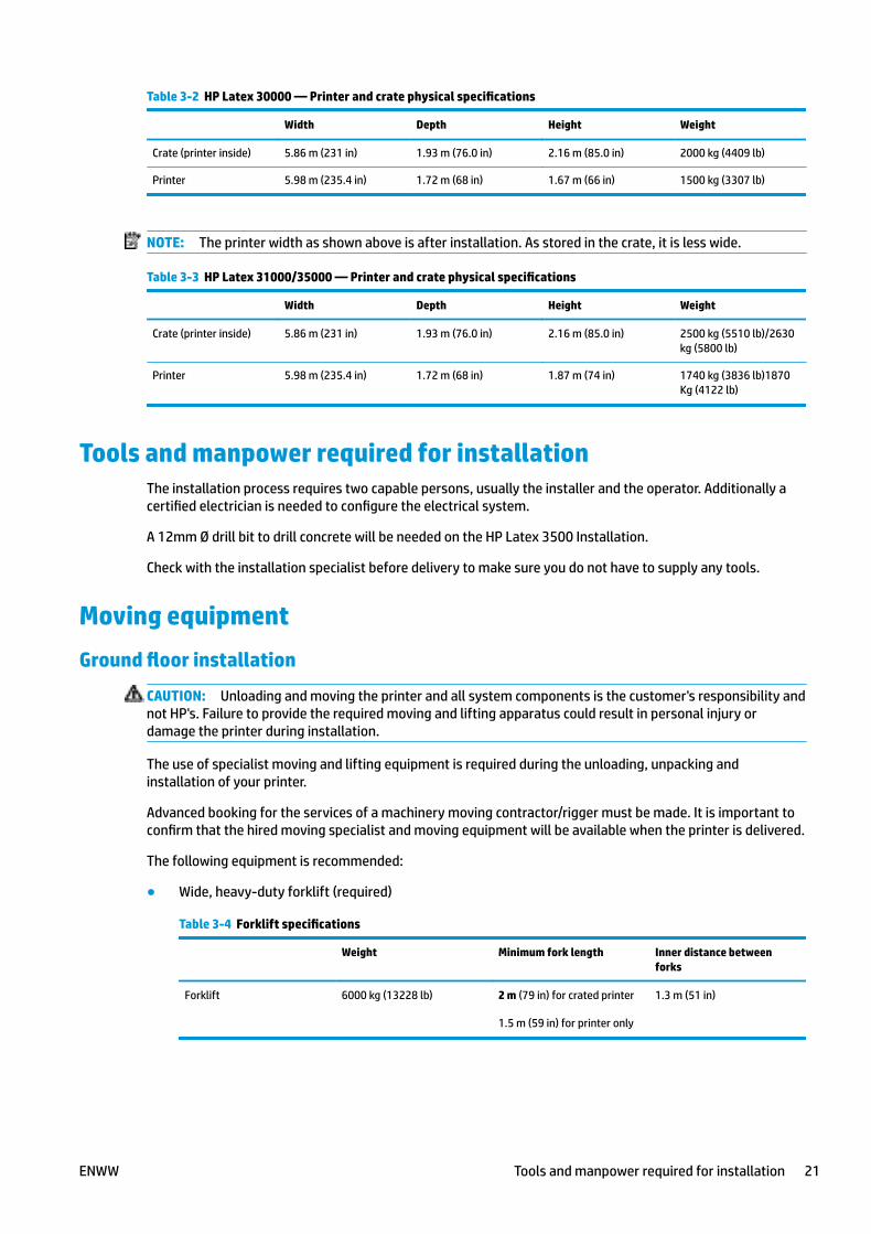
Table 3-2 HP Latex 30000 — Printer and crate physical specifications
Width Depth Height Weight
Crate (printer inside) 5.86 m (231 in) 1.93 m (76.0 in) 2.16 m (85.0 in) 2000 kg (4409 lb)
Printer 5.98 m (235.4 in) 1.72 m (68 in) 1.67 m (66 in) 1500 kg (3307 lb)
NOTE: The printer width as shown above is after installation. As stored in the crate, it is less wide.
Table 3-3 HP Latex 31000/35000 — Printer and crate physical specifications
Width Depth Height Weight
Crate (printer inside) 5.86 m (231 in) 1.93 m (76.0 in) 2.16 m (85.0 in) 2500 kg (5510 lb)/2630kg (5800 lb)
Printer 5.98 m (235.4 in) 1.72 m (68 in) 1.87 m (74 in) 1740 kg (3836 lb)1870Kg (4122 lb)
Tools and manpower required for installationThe installation process requires two capable persons, usually the installer and the operator. Additionally acertified electrician is needed to configure the electrical system.
A 12mm Ø drill bit to drill concrete will be needed on the HP Latex 3500 Installation.
Check with the installation specialist before delivery to make sure you do not have to supply any tools.
Moving equipmentGround floor installation
CAUTION: Unloading and moving the printer and all system components is the customer's responsibility andnot HP's. Failure to provide the required moving and lifting apparatus could result in personal injury ordamage the printer during installation.
The use of specialist moving and lifting equipment is required during the unloading, unpacking andinstallation of your printer.
Advanced booking for the services of a machinery moving contractor/rigger must be made. It is important toconfirm that the hired moving specialist and moving equipment will be available when the printer is delivered.
The following equipment is recommended:
● Wide, heavy-duty forklift (required)
Table 3-4 Forklift specifications
Weight Minimum fork length Inner distance betweenforks
Forklift 6000 kg (13228 lb) 2 m (79 in) for crated printer
1.5 m (59 in) for printer only
1.3 m (51 in)
ENWW Tools and manpower required for installation 21
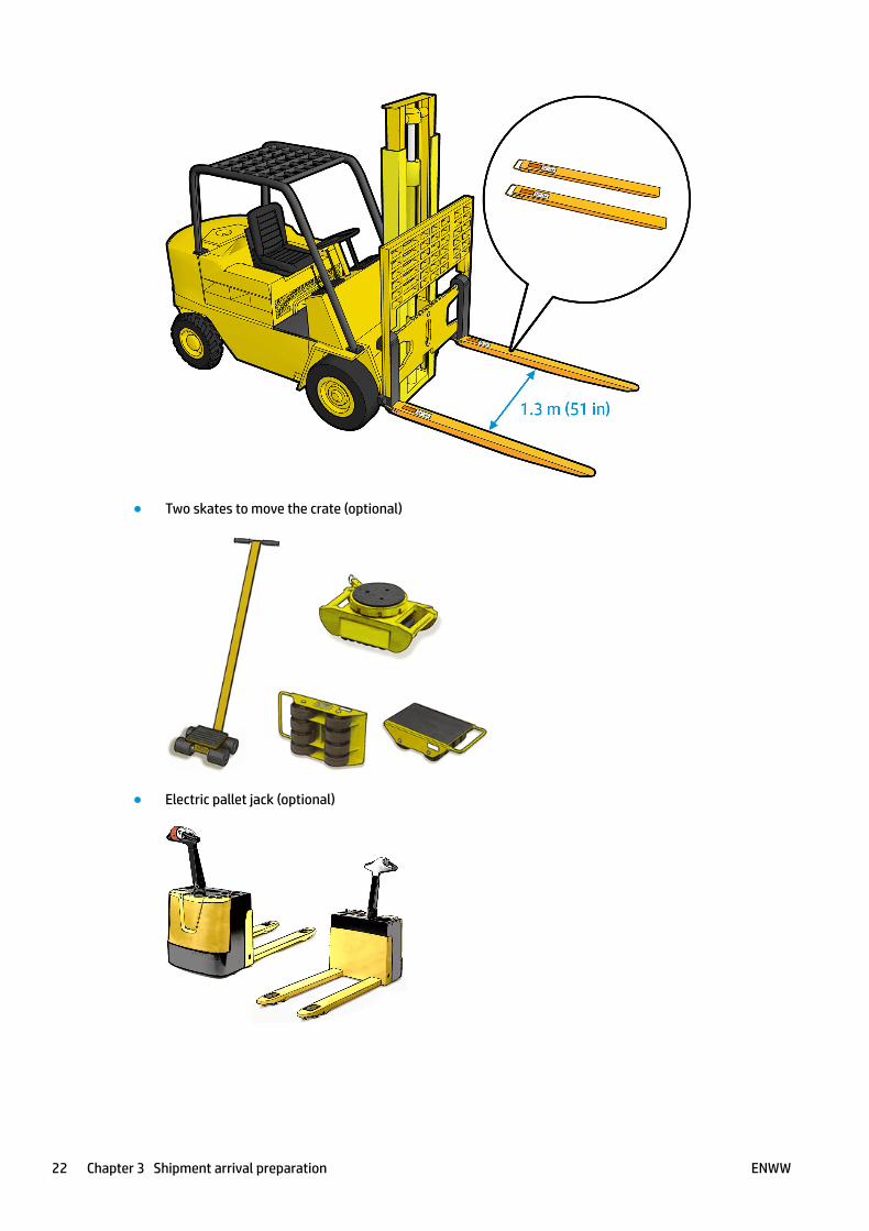
● Two skates to move the crate (optional)
● Electric pallet jack (optional)
22 Chapter 3 Shipment arrival preparation ENWW
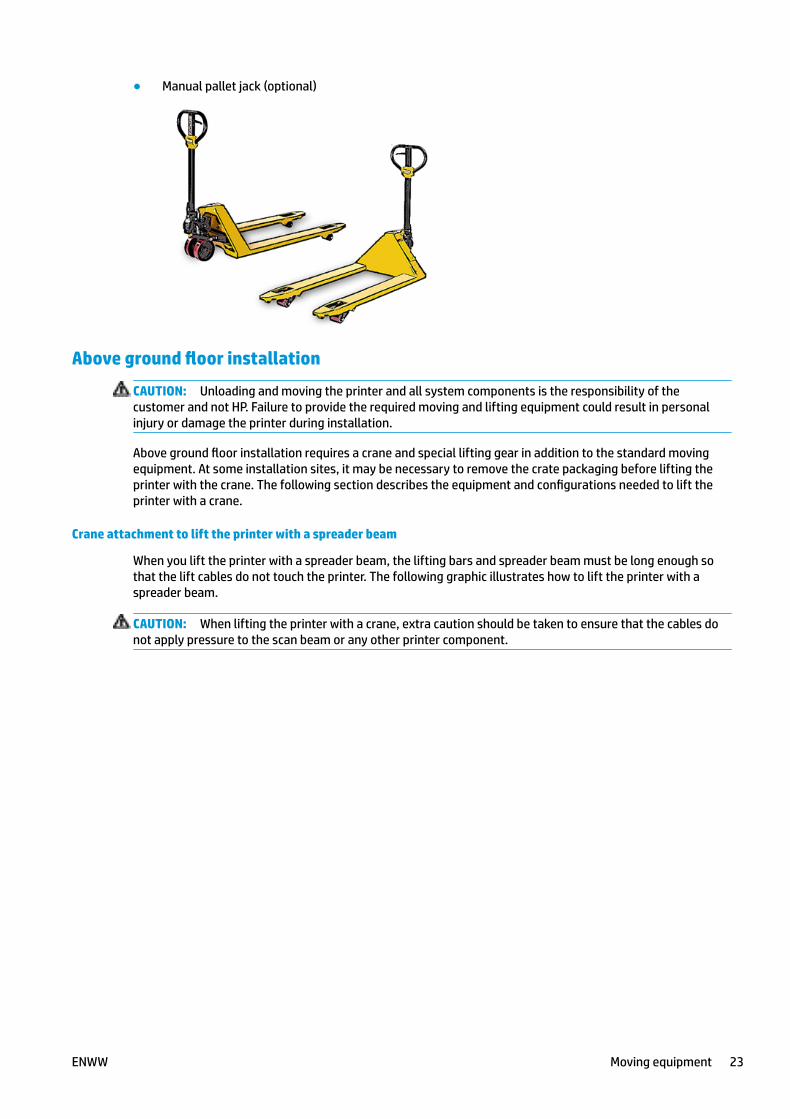
● Manual pallet jack (optional)
Above ground floor installation
CAUTION: Unloading and moving the printer and all system components is the responsibility of thecustomer and not HP. Failure to provide the required moving and lifting equipment could result in personalinjury or damage the printer during installation.
Above ground floor installation requires a crane and special lifting gear in addition to the standard movingequipment. At some installation sites, it may be necessary to remove the crate packaging before lifting theprinter with the crane. The following section describes the equipment and configurations needed to lift theprinter with a crane.
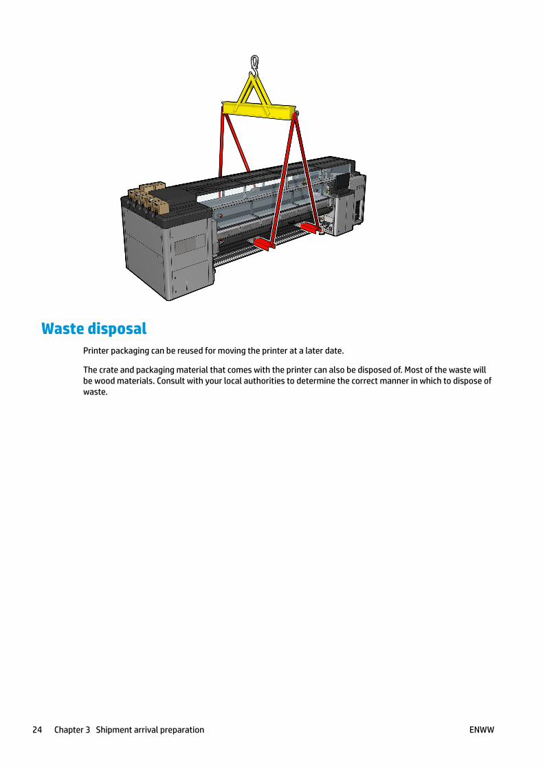
Crane attachment to lift the printer with a spreader beam
When you lift the printer with a spreader beam, the lifting bars and spreader beam must be long enough sothat the lift cables do not touch the printer. The following graphic illustrates how to lift the printer with aspreader beam.
CAUTION: When lifting the printer with a crane, extra caution should be taken to ensure that the cables donot apply pressure to the scan beam or any other printer component.
ENWW Moving equipment 23
Waste disposalPrinter packaging can be reused for moving the printer at a later date.
The crate and packaging material that comes with the printer can also be disposed of. Most of the waste willbe wood materials. Consult with your local authorities to determine the correct manner in which to dispose ofwaste.
24 Chapter 3 Shipment arrival preparation ENWW