Embed Size (px)
Citation preview
J Low Temp PhysDOI 10.1007/s10909-013-0985-4
Latest NIKA Results and the NIKA-2 Project
A. Monfardini · R. Adam · A. Adane · P. Ade · P. André · A. Beelen · B. Belier ·A. Benoit · A. Bideaud · N. Billot · O. Bourrion · M. Calvo · A. Catalano ·G. Coiffard · B. Comis · A. D’Addabbo · F.-X. Désert · S. Doyle · J. Goupy ·C. Kramer · S. Leclercq · J. Macias-Perez · J. Martino · P. Mauskopf ·F. Mayet · F. Pajot · E. Pascale · N. Ponthieu · V. Revéret · L. Rodriguez ·G. Savini · K. Schuster · A. Sievers · C. Tucker · R. Zylka
Received: 15 July 2013 / Accepted: 18 November 2013© Springer Science+Business Media New York 2013
Abstract NIKA (New IRAM KID Arrays) is a dual-band imaging instrument in-stalled at the IRAM (Institut de RadioAstronomie Millimetrique) 30-meter telescope
A. Monfardini (B) · A. Benoit · M. Calvo · A. D’Addabbo · J. GoupyInstitut Néel, CNRS and Université de Grenoble, Grenoble, Francee-mail: [email protected]
R. Adam · O. Bourrion · A. Catalano · B. Comis · J. Macias-Perez · F. MayetLaboratoire de Physique Subatomique et de Cosmologie (LPSC), CNRS and Université de Grenoble,Grenoble, France
A. Adane · G. Coiffard · S. Leclercq · K. SchusterInstitut de RadioAstronomie Millimetrique (IRAM), Grenoble, France
P. Ade · A. Bideaud · S. Doyle · P. Mauskopf · E. Pascale · C. TuckerAstronomy Instrumentation Group, University of Cardiff, Cardiff, UK
P. André · V. Revéret · L. RodriguezCEA-Irfu, Saclay, France
A. Beelen · J. Martino · F. PajotInstitut d’Astrophysique Spatiale (IAS), CNRS and Université Paris Sud, Orsay, France
B. BelierInstitut d’Electronique Fondamentale (IEF), Université Paris Sud, Orsay, France
F.-X. Désert · N. PonthieuInstitut de Planétologie et dAstrophysique de Grenoble (IPAG), CNRS and Université de Grenoble,Grenoble, France
N. Billot · C. Kramer · A. Sievers · R. ZylkaInstituto Radioastronomía Milimétrica (IRAM), Granada, Spain
G. SaviniUniversity College London (UCL), London, UK
J Low Temp Phys
at Pico Veleta (Spain). Two distinct Kinetic Inductance Detectors (KID) focal planesallow the camera to simultaneous image a field-of-view of about 2 arc-min in thebands 125 to 175 GHz (150 GHz) and 200 to 280 GHz (240 GHz). The sensitiv-ity and stability achieved during the last commissioning Run in June 2013 allowsopening the instrument to general observers. We report here the latest results, in par-ticular in terms of sensitivity, now comparable to the state-of-the-art Transition EdgeSensors (TES) bolometers, relative and absolute photometry. We describe briefly thenext generation NIKA-2 instrument, selected by IRAM to occupy, from 2015, thecontinuum imager/polarimeter slot at the 30-m telescope.
Keywords Kinetic inductance detectors · Millimeter astronomy · Superconductingdetectors
1 Introduction
Millimeter astronomy, traditionally important for the study of the early/cold evolu-tionary stages of the main astrophysical objects, i.e. stars, galaxies, is now a centralsubject for cosmological studies too. This interest has been further boosted by therecent Planck multi-band (22 GHz to 850 GHz) surveys [1]. In addition, the Herschelspace telescope, operated at sub-millimeter and far-infrared wavelengths, mappedefficiently large portions [2] of the Sky discovering a huge number of potentially in-teresting follow-up sources for a large ground-based telescope operating at longerwavelenghts. The 30-m IRAM telescope (Pico Veleta, Spain, 2850 meters a.s.l.) is,with its 6.5 arc-min field-of-view (FoV) and angular resolution of 10 arc-sec at 240GHz (16 arc-sec at 150 GHz), a crucial tool to bridge, in terms of sensitivity and an-gular scale, between the ground-based interferometers (e.g. ALMA [3] and NOEMA[4], high angular resolution, high sensitivity, small field-of-view) and the small Spacetelescopes (e.g. Planck, coarse angular resolution, moderate limiting sensitivity, sur-veys). The IRAM telescope is already equipped with state-of-the-art heterodyne in-struments performing high-resolution spectroscopy between 74 GHz and 360 GHz.A large field-of-view, multicolor continuum instrument able to detect fainter sourcesis the natural complement to the existing instrumentation.
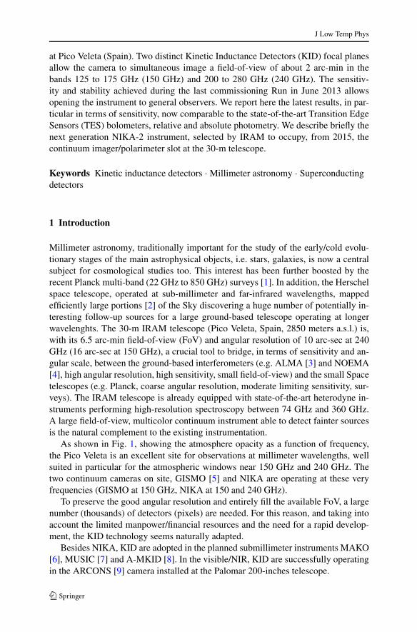
As shown in Fig. 1, showing the atmosphere opacity as a function of frequency,the Pico Veleta is an excellent site for observations at millimeter wavelengths, wellsuited in particular for the atmospheric windows near 150 GHz and 240 GHz. Thetwo continuum cameras on site, GISMO [5] and NIKA are operating at these veryfrequencies (GISMO at 150 GHz, NIKA at 150 and 240 GHz).
To preserve the good angular resolution and entirely fill the available FoV, a largenumber (thousands) of detectors (pixels) are needed. For this reason, and taking intoaccount the limited manpower/financial resources and the need for a rapid develop-ment, the KID technology seems naturally adapted.
Besides NIKA, KID are adopted in the planned submillimeter instruments MAKO[6], MUSIC [7] and A-MKID [8]. In the visible/NIR, KID are successfully operatingin the ARCONS [9] camera installed at the Palomar 200-inches telescope.
J Low Temp Phys
Fig. 1 Atmosphere opacity(zenith) at Pico Veleta. Red:2 mm precipitable water vapor(pwv), good observingconditions; Blue: 7 mm pwv,average summer conditions(Color figure online)
2 The NIKA Development: 2009–2013
The NIKA program started in November 2008, mainly driven by the new technologydevelopments ongoing on the Kinetic Inductance Detectors (KID) at SRON, Cardiffand Institut Néel, Grenoble. The goal, as already explained in the Introduction, wasto equip the large millimeter telescope at Pico Veleta with an innovative deep-fieldcamera. At that time, multiplexed KID hadn’t been demonstrated yet at a telescope,and the achieved sensitivities on the sky were still rather poor. Despite that, newideas like the Lumped Element KID (LEKID) proposed by Doyle et al. [10] and theencouraging preliminary results concerning antenna-coupled KID [11] convinced usthat building such an instrument was possible in a relatively short amount of time.Three European laboratories (Institut Neel, AIG Cardiff, SRON) decided on this baseto start an intense phase of development culminated in October 2009, i.e. less thanone year after the kick-off, in the first astronomical light for a multiplexed (MUX)KID camera. In the first observational run we demonstrated the performances of bothantenna-coupled detectors and LEKID at 150 GHz [13]. From the MUX electron-ics point-of-view, we used during the observations both an FFTS [14] (Fast FourierTransform Spectrometer) system and a more classical DDC [15] (Direct Down Con-version). Despite the still poor sensitivities, the run was a big success from the tech-nological point-of-view.
In Run 2, in October 2010, NIKA wa improved to a dual-band [16] (150 GHz and240 GHz) instrument. Also, it had grown already to a hundreds pixels fully multi-plexed instrument. For that test, we adopted single polarization LEKID at 150 GHzand antenna-coupled KID at 240 GHz. The sensitivity at 150 GHz improved by afactor of three compared to the previous experience.
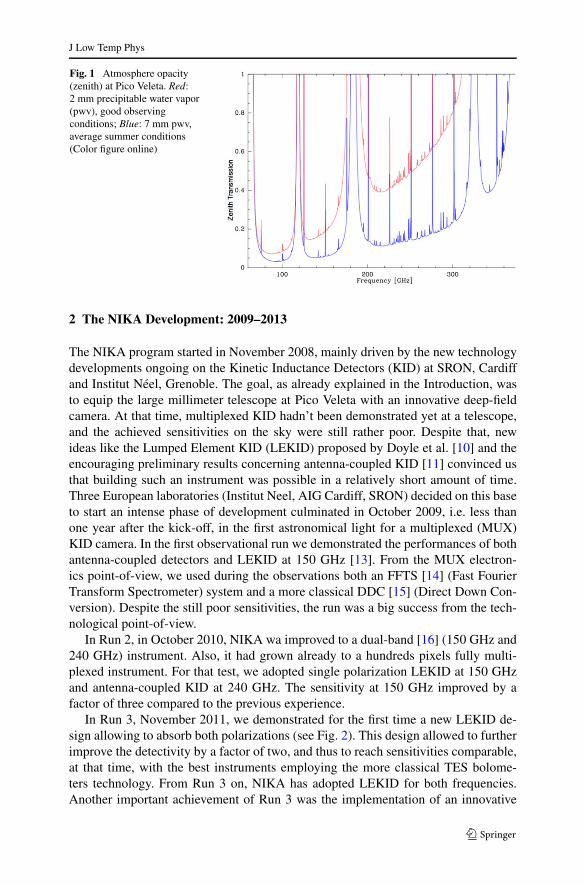
In Run 3, November 2011, we demonstrated for the first time a new LEKID de-sign allowing to absorb both polarizations (see Fig. 2). This design allowed to furtherimprove the detectivity by a factor of two, and thus to reach sensitivities comparable,at that time, with the best instruments employing the more classical TES bolome-ters technology. From Run 3 on, NIKA has adopted LEKID for both frequencies.Another important achievement of Run 3 was the implementation of an innovative
J Low Temp Phys
Fig. 2 The NIKA LEKIDdesign based on a fractal-shapedinductor and an interdigitedcapacitor. The LEKID isinductively coupled to aCoPlanar Waveguide (CPW).Black: thin (e.g. 20 nm)Aluminium; white: Siliconsubstrate. The pixel size is about2 mm. The main designparameters are shown in thedrawing and explained in moredetail in Roesch et al. [12]
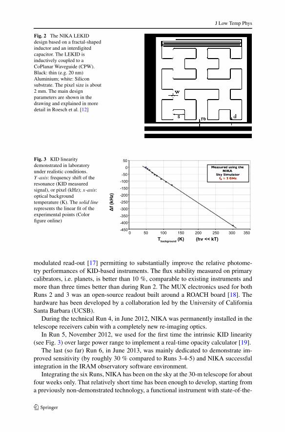
Fig. 3 KID linearitydemonstrated in laboratoryunder realistic conditions.Y -axis: frequency shift of theresonance (KID measuredsignal), or pixel (kHz); x-axis:optical backgroundtemperature (K). The solid linerepresents the linear fit of theexperimental points (Colorfigure online)
modulated read-out [17] permitting to substantially improve the relative photome-try performances of KID-based instruments. The flux stability measured on primarycalibrators, i.e. planets, is better than 10 %, comparable to existing instruments andmore than three times better than during Run 2. The MUX electronics used for bothRuns 2 and 3 was an open-source readout built around a ROACH board [18]. Thehardware has been developed by a collaboration led by the University of CaliforniaSanta Barbara (UCSB).
During the technical Run 4, in June 2012, NIKA was permanently installed in thetelescope receivers cabin with a completely new re-imaging optics.
In Run 5, November 2012, we used for the first time the intrinsic KID linearity(see Fig. 3) over large power range to implement a real-time opacity calculator [19].
The last (so far) Run 6, in June 2013, was mainly dedicated to demonstrate im-proved sensitivity (by roughly 30 % compared to Runs 3-4-5) and NIKA successfulintegration in the IRAM observatory software environment.
Integrating the six Runs, NIKA has been on the sky at the 30-m telescope for aboutfour weeks only. That relatively short time has been enough to develop, starting froma previously non-demonstrated technology, a functional instrument with state-of-the-
J Low Temp Phys
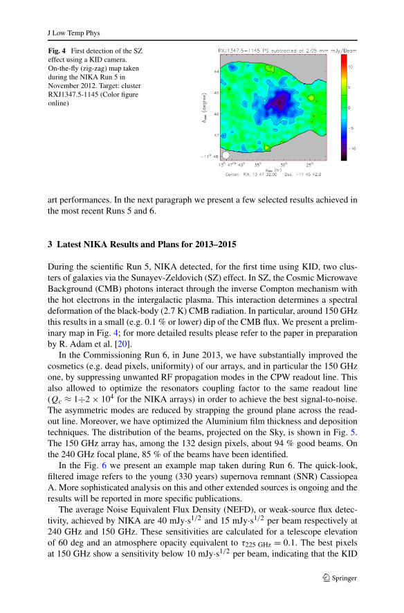
Fig. 4 First detection of the SZeffect using a KID camera.On-the-fly (zig-zag) map takenduring the NIKA Run 5 inNovember 2012. Target: clusterRXJ1347.5-1145 (Color figureonline)
art performances. In the next paragraph we present a few selected results achieved inthe most recent Runs 5 and 6.
3 Latest NIKA Results and Plans for 2013–2015
During the scientific Run 5, NIKA detected, for the first time using KID, two clus-ters of galaxies via the Sunayev-Zeldovich (SZ) effect. In SZ, the Cosmic MicrowaveBackground (CMB) photons interact through the inverse Compton mechanism withthe hot electrons in the intergalactic plasma. This interaction determines a spectraldeformation of the black-body (2.7 K) CMB radiation. In particular, around 150 GHzthis results in a small (e.g. 0.1 % or lower) dip of the CMB flux. We present a prelim-inary map in Fig. 4; for more detailed results please refer to the paper in preparationby R. Adam et al. [20].
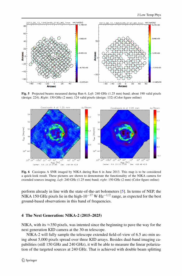
In the Commissioning Run 6, in June 2013, we have substantially improved thecosmetics (e.g. dead pixels, uniformity) of our arrays, and in particular the 150 GHzone, by suppressing unwanted RF propagation modes in the CPW readout line. Thisalso allowed to optimize the resonators coupling factor to the same readout line(Qc ≈ 1÷2 × 10⁴ for the NIKA arrays) in order to achieve the best signal-to-noise.The asymmetric modes are reduced by strapping the ground plane across the read-out line. Moreover, we have optimized the Aluminium film thickness and depositiontechniques. The distribution of the beams, projected on the Sky, is shown in Fig. 5.The 150 GHz array has, among the 132 design pixels, about 94 % good beams. Onthe 240 GHz focal plane, 85 % of the beams have been identified.
In the Fig. 6 we present an example map taken during Run 6. The quick-look,filtered image refers to the young (330 years) supernova remnant (SNR) CassiopeaA. More sophisticated analysis on this and other extended sources is ongoing and theresults will be reported in more specific publications.
The average Noise Equivalent Flux Density (NEFD), or weak-source flux detec-tivity, achieved by NIKA are 40 mJy·s1/2 and 15 mJy·s1/2 per beam respectively at240 GHz and 150 GHz. These sensitivities are calculated for a telescope elevationof 60 deg and an atmosphere opacity equivalent to τ225 GHz = 0.1. The best pixelsat 150 GHz show a sensitivity below 10 mJy·s1/2 per beam, indicating that the KID
J Low Temp Phys
Fig. 5 Projected beams measured during Run 6. Left: 240 GHz (1.25 mm) band; about 190 valid pixels(design: 224). Right: 150 GHz (2 mm); 124 valid pixels (design: 132) (Color figure online)
Fig. 6 Cassiopea A SNR imaged by NIKA during Run 6 in June 2013. This map is to be considereda quick-look result. These pictures are shown to demonstrate the functionality of the NIKA camera forextended sources imaging. Left: 240 GHz (1.25 mm) band; right: 150 GHz (2 mm) (Color figure online)
perform already in line with the state-of-the-art bolometers [5]. In terms of NEP, theNIKA 150 GHz pixels lie in the high-10−17 W·Hz−1/2 range, as expected for the bestground-based observations in this band of frequencies.
4 The Next Generation: NIKA-2 (2015–2025)
NIKA, with its ≈350 pixels, was intented since the beginning to pave the way for thenext generation KID camera at the 30-m telescope.
NIKA-2 will fully sample the telescope extended field-of-view of 6.5 arc-min us-ing about 5,000 pixels spread over three KID arrays. Besides dual-band imaging ca-pabilities (still 150 GHz and 240 GHz), it will be able to measure the linear polariza-tion of the targeted sources at 240 GHz. That is achieved with double beam splitting
J Low Temp Phys
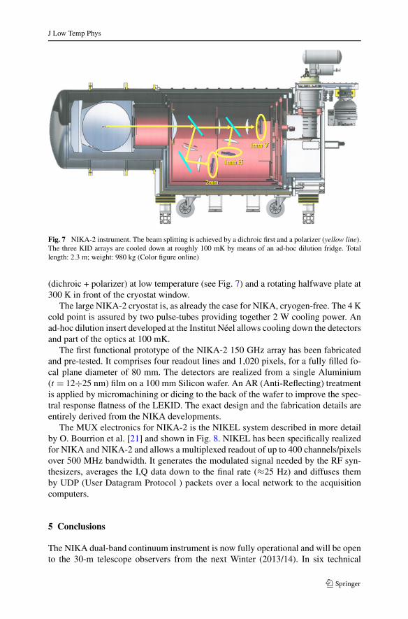
Fig. 7 NIKA-2 instrument. The beam splitting is achieved by a dichroic first and a polarizer (yellow line).The three KID arrays are cooled down at roughly 100 mK by means of an ad-hoc dilution fridge. Totallength: 2.3 m; weight: 980 kg (Color figure online)
(dichroic + polarizer) at low temperature (see Fig. 7) and a rotating halfwave plate at300 K in front of the cryostat window.
The large NIKA-2 cryostat is, as already the case for NIKA, cryogen-free. The 4 Kcold point is assured by two pulse-tubes providing together 2 W cooling power. Anad-hoc dilution insert developed at the Institut Néel allows cooling down the detectorsand part of the optics at 100 mK.
The first functional prototype of the NIKA-2 150 GHz array has been fabricatedand pre-tested. It comprises four readout lines and 1,020 pixels, for a fully filled fo-cal plane diameter of 80 mm. The detectors are realized from a single Aluminium(t = 12÷25 nm) film on a 100 mm Silicon wafer. An AR (Anti-Reflecting) treatmentis applied by micromachining or dicing to the back of the wafer to improve the spec-tral response flatness of the LEKID. The exact design and the fabrication details areentirely derived from the NIKA developments.
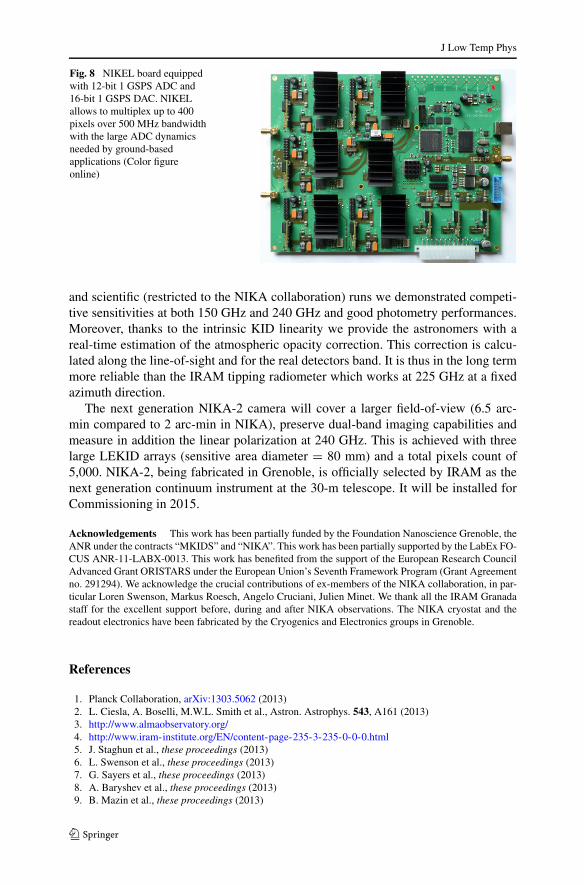
The MUX electronics for NIKA-2 is the NIKEL system described in more detailby O. Bourrion et al. [21] and shown in Fig. 8. NIKEL has been specifically realizedfor NIKA and NIKA-2 and allows a multiplexed readout of up to 400 channels/pixelsover 500 MHz bandwidth. It generates the modulated signal needed by the RF syn-thesizers, averages the I,Q data down to the final rate (≈25 Hz) and diffuses themby UDP (User Datagram Protocol ) packets over a local network to the acquisitioncomputers.
5 Conclusions
The NIKA dual-band continuum instrument is now fully operational and will be opento the 30-m telescope observers from the next Winter (2013/14). In six technical
J Low Temp Phys
Fig. 8 NIKEL board equippedwith 12-bit 1 GSPS ADC and16-bit 1 GSPS DAC. NIKELallows to multiplex up to 400pixels over 500 MHz bandwidthwith the large ADC dynamicsneeded by ground-basedapplications (Color figureonline)
and scientific (restricted to the NIKA collaboration) runs we demonstrated competi-tive sensitivities at both 150 GHz and 240 GHz and good photometry performances.Moreover, thanks to the intrinsic KID linearity we provide the astronomers with areal-time estimation of the atmospheric opacity correction. This correction is calcu-lated along the line-of-sight and for the real detectors band. It is thus in the long termmore reliable than the IRAM tipping radiometer which works at 225 GHz at a fixedazimuth direction.
The next generation NIKA-2 camera will cover a larger field-of-view (6.5 arc-min compared to 2 arc-min in NIKA), preserve dual-band imaging capabilities andmeasure in addition the linear polarization at 240 GHz. This is achieved with threelarge LEKID arrays (sensitive area diameter = 80 mm) and a total pixels count of5,000. NIKA-2, being fabricated in Grenoble, is officially selected by IRAM as thenext generation continuum instrument at the 30-m telescope. It will be installed forCommissioning in 2015.
Acknowledgements This work has been partially funded by the Foundation Nanoscience Grenoble, theANR under the contracts “MKIDS” and “NIKA”. This work has been partially supported by the LabEx FO-CUS ANR-11-LABX-0013. This work has benefited from the support of the European Research CouncilAdvanced Grant ORISTARS under the European Union’s Seventh Framework Program (Grant Agreementno. 291294). We acknowledge the crucial contributions of ex-members of the NIKA collaboration, in par-ticular Loren Swenson, Markus Roesch, Angelo Cruciani, Julien Minet. We thank all the IRAM Granadastaff for the excellent support before, during and after NIKA observations. The NIKA cryostat and thereadout electronics have been fabricated by the Cryogenics and Electronics groups in Grenoble.
References
1. Planck Collaboration, arXiv:1303.5062 (2013)2. L. Ciesla, A. Boselli, M.W.L. Smith et al., Astron. Astrophys. 543, A161 (2013)3. http://www.almaobservatory.org/4. http://www.iram-institute.org/EN/content-page-235-3-235-0-0-0.html5. J. Staghun et al., these proceedings (2013)6. L. Swenson et al., these proceedings (2013)7. G. Sayers et al., these proceedings (2013)8. A. Baryshev et al., these proceedings (2013)9. B. Mazin et al., these proceedings (2013)
J Low Temp Phys
10. S. Doyle, P. Mauskopf, J. Naylon et al., J. Low Temp. Phys. 151, 530 (2008)11. S.J.C. Yates, J.J.A. Baselmans, A.M. Baryshev et al., AIP Proc. 1185, 144 (2009)12. M. Roesch et al., arXiv:1212.4585 (2012)13. A. Monfardini, L.J. Swenson, A. Bideaud et al., Astron. Astrophys. 521, A29 (2010)14. S.J.C. Yates et al., Appl. Phys. Lett. 95, 042504 (2009)15. L.J. Swenson et al., AIP Proc. 1185, 84 (2009)16. A. Monfardini, A. Benoit, A. Bideaud et al., Astrophys. J. Suppl. Ser. 194(2), 24 (2011)17. M. Calvo, M. Roesch, F.-X. Désert et al., Astron. Astrophys. 551, L12 (2013)18. R. Duan et al., Proc. SPIE 7741, 77411V (2010)19. A. Catalano, M. Calvo, N. Ponthieu et al., in preparation (2013)20. R. Adam et al., in preparation (2013)21. O. Bourrion, A. Bideaud, A. Benoit et al., J. Instrum. 6, P06012 (2011)