Embed Size (px)
Citation preview

Latest ITU-T Recommendations K series: Protection against
interference (SG5, WP1, Q2-Q5)
Presented by Mick Maytum
Prepared by Mick MAYTUM, ITU-T SG5 Q2 Rapporteur, ICT Consultant &
Tatjana GAZIVODA-NIKOLIC, Associate Q2 rapporteur, Bourns, Inc.
24-26 March 2015Huntsville, Alabama
PROTECTIONENGINEERSGROUP CONFERENCE
Latest ITU-TSurge Protection
K Recommendations

This presentation lists recent ITU-T, Study Group 5, K series Recommendations concerned with surge protection from Working Party 1, Questions 2 through 5. Each new or revised Recommendation is covered in terms of title, URL (if available), summary and points of technical interest. From the information provided, readers can decide if a document warrants more detailed study.
24-26 March 2015Huntsville, Alabama
PROTECTIONENGINEERSGROUP CONFERENCE
Latest ITU-TSurge Protection
K Recommendations
New Recommendations: K.95: Surge parameters of isolating transformers used in telecommunication devices and equipment K.96: Surge protective components: Overview of surge mitigation functions and technologies K.97: Lightning protection of distributed base stations K.98: Overvoltage protection guide for telecommunications equipment installed in customer premises K.99: Surge protective component application guide - Gas discharge tubes K.102: Parameters of fixed-voltage thyristor overvoltage protector components used for the protection of telecommunication installations K.103: Surge protective component application guide - Silicon PN junction clamping components K.104: Method for identifying the transfer potential of EPR from HV and/or MV to the earthing system or neutral of LV network K.105: Lightning protection of photovoltaic power supply system feeding a radio base station
24-26 March 2015Huntsville, Alabama
PROTECTIONENGINEERSGROUP CONFERENCE
Latest ITU-TSurge Protection
K Recommendations

K.95 (02/2014): Surge parameters of isolating transformers used in telecommunication devices and equipment
https://www.itu.int/rec/dologin_pub.asp?lang=e&id=T-REC-K.95-201402-I!!PDF-E&type=items
Summary: Telecommunication devices and equipment can use non-linear limiting, linear attenuating, or both types of functions to mitigate surges occurring on services. Isolating transformers attenuate common-mode voltage surges on a service. Recommendation ITU-T K.95 gives test methods and preferred values for the isolating transformer surge parameters that are harmonized with established international standards on insulation coordination levels and test techniques.
24-26 March 2015Huntsville, Alabama
PROTECTIONENGINEERSGROUP CONFERENCE
Latest ITU-TSurge Protection
K Recommendations

K.95 (02/2014): Surge parameters of isolating transformers used in telecommunication devices and equipment
24-26 March 2015Huntsville, Alabama
PROTECTIONENGINEERSGROUP CONFERENCE
Latest ITU-TSurge Protection
K Recommendations
Main Contents
Surge parameters: Transformer surge mitigation, Common-mode surges, Differential-mode surges
Characteristics: Characteristic measurement, Inter-winding capacitance, Insulation resistance, Signal transformer voltage-time product
Ratings: Rating verification, Rated impulse voltage, Signal transformer rated winding d.c.
Rated impulse voltage (kV) Impulse withstand voltage (kV)
1.5 1.75
2.5 2.92
4 4.92
6 7.39
K.96 (02/2014): Surge protective components: Overview of surge mitigation functions and technologies
https://www.itu.int/rec/dologin_pub.asp?lang=e&id=T-REC-K.96-201402-I!!PDF-E&type=items
Summary: Recommendation ITU-T K.96 presents information on the basic forms of surge mitigation and component technologies available to device and equipment designers. Following this basic Recommendation, further Recommendations in this surge protective components series will describe the applications principles of specific component technologies.
24-26 March 2015Huntsville, Alabama
PROTECTIONENGINEERSGROUP CONFERENCE
Latest ITU-TSurge Protection
K Recommendations

K.96 (02/2014): Surge protective components: Overview of surge mitigation functions and technologies
24-26 March 2015Huntsville, Alabama
PROTECTIONENGINEERSGROUP CONFERENCE
Latest ITU-TSurge Protection
K Recommendations
Low-pass High-passBand-pass
Frequency Selective
Continuous
Characteristic1
Discontinuous
Characteristic2
Overvoltage
Surge Mitigation Functions
Common-mode/Differential-mode Mitigation
Common-mode/Differential-mode Mitigation
Overcurrent
1 Clamping characteristic2 Switching characteristic, has a switching transition
Continuous
Characteristic1
Discontinuous
Characteristic2
Differential-mode Mitigation
EMC ChokeNeutralisingIsolating
Transformer Action
Common-mode Mitigation
Linear SuppressionNon-linear Limiting
K.97 (02/2014): Lightning protection of distributed base stations
https://www.itu.int/rec/dologin_pub.asp?lang=e&id=T-REC-K.97-201402-I!!PDF-E&type=items
Summary: Recommendation ITU-T K.97 deals with lightning protection of a distributed base station (DBS) on the tower site. A DBS is a new type of radio base station which consists of a remote radio unit (RRU) located on the tower, and a base band unit (BBU) inside the shelter at the bottom of the tower. Lightning protection of DBS is not fully covered by Recommendation ITU-T K.56. The main objective of this Recommendation is the lightning protection of RRU and rectifier interfaces with direct current (DC) power cable, and bonding of the DBS. Protection of these interfaces is achieved by installing a protection module. Possible protection schemes for such installations are also described. This Recommendation indicates when these protection modules should be used, and provides indication of their withstand current. The surge protective device (SPD) needed on the feeder cable is also indicated. Bonding configurations of the protection module and of the optical fibre cable are also illustrated. Appendix I shows an example of an isolated protection solution.
24-26 March 2015Huntsville, Alabama
PROTECTIONENGINEERSGROUP CONFERENCE
Latest ITU-TSurge Protection
K Recommendations

K.97 (02/2014): Lightning protection of distributed base stations
24-26 March 2015Huntsville, Alabama
PROTECTIONENGINEERSGROUP CONFERENCE
Latest ITU-TSurge Protection
K Recommendations
Key Contents
- Protection of DBS (Distributed Base Station): Protection need, RRU (Remote Radio Unit) protection, Protection of rectifier, The need for feeder SPD
- Bonding of DBS: Bonding RRU and protection module, DC power cable, Bonding configuration of protection module at rectifier side, BBU (Base Band Unit) bonding, Bonding of optical fibre cable
- Appendices: I – Isolated protection solution: Example, II – Assessment of the energy delivered to clamping type SPC used in RRU protection module (see Towering Powering protection problem on Remote Radio Head (RRH) cellular systems, PEG 2012) The PEG 2012 paper findings were further expanded by Remote Radio Unit (RRU) DC Feed protection, which analyses the SPD energy for various lightning waveforms.
K.98 (08/2014): Overvoltage protection guide for telecommunication equipment installed in customer premises
Not freely available: Consented in approval and editing
Summary: This Recommendation contains the information needed to protect telecommunications equipment installed in customer premises from damage due to lightning strikes to the power and telecommunications lines/cables. It shows that it is possible to protect equipment against a direct strike to the incoming service (power or telecommunications) providing that the strike point is more than a couple of hundred metres from the customer premises in an urban area. The information provided takes into consideration the impact of the different types of power distribution systems. It determines the impact of both the length of the telecommunication Surge Protection Device (SPD) bonding conductor and the resistance to earth at the customer’s premise. It also calculates the necessary isolation level for the protection of equipment without the use of primary protection. It recommends the installation of a Multiservice Surge Protective Device (MSPD) or equivalent protection as the first level of protection. When necessary, primary protection is required to protect the MSPD or equivalent protection. For strikes to the services closer to the customer premises an engineering solution is required.
24-26 March 2015Huntsville, Alabama
PROTECTIONENGINEERSGROUP CONFERENCE
Latest ITU-TSurge Protection
K Recommendations

K.98 (08/2014): Overvoltage protection guide for telecommunication equipment installed in customer premises Subject of Thursday presentation “Direct Lightning Strike Surge Propagation in Customer Premises Wiring”. This presentation analyses the contents of ITU-T K.98: Overvoltage protection guide for telecommunications equipment installed in customer premises. K.98 has over 160 pages and over 30 customer premise wiring voltage and current plots for the first 100 µs or more of the surge. A simulated lightning strike of 5/75 is used based on the findings of CIGRÉ TB 549 (2013) Lightning Parameters for Engineering Applications (covered at PEG 2014). The lightning strike is assumed to be either to the telecommunications line or the a.c. mains supply. This international document considers mains configuration types of TN-S, TN-C, TN-C-S, TT and IT. The effects of various earthing system lead lengths and earth electrode resistances are also considered. The information in K.98 can be used to identify the most at risk customer premise situations for direct lightning damage
24-26 March 2015Huntsville, Alabama
PROTECTIONENGINEERSGROUP CONFERENCE
Latest ITU-TSurge Protection
K Recommendations
K.99 (08/2014): Surge protective component application guide - Gas discharge tubes
https://www.itu.int/rec/dologin_pub.asp?lang=e&id=T-REC-K.99-201408-I!!PDF-E&type=items
Summary: Recommendation ITU-T K.99 describes the construction, characteristics, ratings and application examples of gas discharge tubes (GDTs) intended for the protection of exchange and outdoor equipment, subscriber or customer equipment and telecommunication lines from surges.
24-26 March 2015Huntsville, Alabama
PROTECTIONENGINEERSGROUP CONFERENCE
Latest ITU-TSurge Protection
K Recommendations
K.99 (08/2014): Surge protective component application guide - Gas discharge tubes
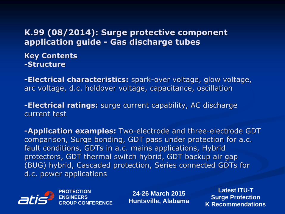
Key Contents -Structure
-Electrical characteristics: spark-over voltage, glow voltage, arc voltage, d.c. holdover voltage, capacitance, oscillation -Electrical ratings: surge current capability, AC discharge current test -Application examples: Two-electrode and three-electrode GDT comparison, Surge bonding, GDT pass under protection for a.c. fault conditions, GDTs in a.c. mains applications, Hybrid protectors, GDT thermal switch hybrid, GDT backup air gap (BUG) hybrid, Cascaded protection, Series connected GDTs for d.c. power applications
24-26 March 2015Huntsville, Alabama
PROTECTIONENGINEERSGROUP CONFERENCE
Latest ITU-TSurge Protection
K Recommendations
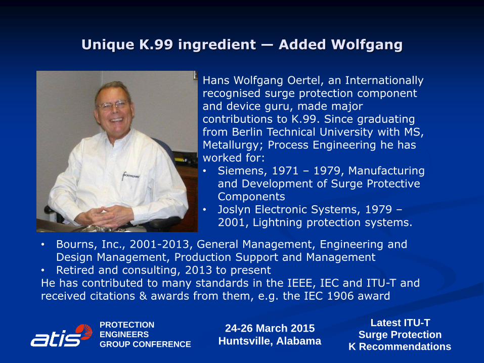
Unique K.99 ingredient — Added Wolfgang
24-26 March 2015Huntsville, Alabama
PROTECTIONENGINEERSGROUP CONFERENCE
Latest ITU-TSurge Protection
K Recommendations
Hans Wolfgang Oertel, an Internationally recognised surge protection component and device guru, made major contributions to K.99. Since graduating from Berlin Technical University with MS, Metallurgy; Process Engineering he has worked for: • Siemens, 1971 – 1979, Manufacturing
and Development of Surge Protective Components
• Joslyn Electronic Systems, 1979 – 2001, Lightning protection systems.
• Bourns, Inc., 2001-2013, General Management, Engineering and Design Management, Production Support and Management
• Retired and consulting, 2013 to present He has contributed to many standards in the IEEE, IEC and ITU-T and received citations & awards from them, e.g. the IEC 1906 award
K.102 (08/2014): Parameters of fixed-voltage thyristor overvoltage protector components used for the protection of telecommunication installations
https://www.itu.int/rec/dologin_pub.asp?lang=e&id=T-REC-K.102-201408-I!!PDF-E&type=items
Summary: Recommendation ITU-T K.102 defines the basic electrical parameters to be met by fixed-voltage thyristor overvoltage protector components used for the protection of telecommunications equipment or lines from surges. Examples of equipment include those located either within a telecommunications centre [b-ITU-T K.20], customer premises [b-ITU-T K.21], in access or in trunk networks [b-ITU-T K.45]. It is intended that this Recommendation be used for the harmonization of existing or future specifications issued by thyristor surge protective component manufacturers, telecommunication equipment manufacturers, administrations or network operators.
24-26 March 2015Huntsville, Alabama
PROTECTIONENGINEERSGROUP CONFERENCE
Latest ITU-TSurge Protection
K Recommendations
K.102 (08/2014): Parameters of fixed-voltage thyristor overvoltage protector components used for the protection of telecommunication installations
This Recommendation harmonises with various IEC standards for fixed voltage thyristor schematic symbols, letter symbols, definitions, characteristics and ratings. It provides a normative reference for the future “Surge protective component application guide – fixed voltage thyristors “ document. Gated thyristors are sufficiently complex to have their own parameter and application guide documents at a future date.
24-26 March 2015Huntsville, Alabama
PROTECTIONENGINEERSGROUP CONFERENCE
Latest ITU-TSurge Protection
K Recommendations
K.103: Surge protective component application guide - Silicon PN junction components
Not freely available: Consented (12/2014) in approval and editing
Summary: This Recommendation in the Surge Protective Component Application Guide series covers voltage limiting components, having one or two silicon PN junctions. These surge protective components (SPCs) are clamping type overvoltage protectors [b-ITU-T K.96]. Components covered use the following PN junction technologies; Zener breakdown, avalanche breakdown, fold-back, punch-through and rectification. Guidance is given on construction, characteristics, ratings and application examples.
24-26 March 2015Huntsville, Alabama
PROTECTIONENGINEERSGROUP CONFERENCE
Latest ITU-TSurge Protection
K Recommendations
K.103: Surge protective component application guide - Silicon PN junction components
Key Contents: - Construction: Packaging, Semiconductor junction structure and electrical properties, Single PN junction structure and electrical characteristic, NPN or PNP junction structures and electrical characteristics. - Characteristics: Stand-off or maximum reverse working voltage, Breakdown voltage, Clamping voltage, Punch-through voltage, Snap back voltage, Forward biased PN junction voltage, Junction capacitance, Package inductance. - Ratings: Peak pulse current, Maximum peak pulse power, Power dissipation. - Application examples: Series connection, Parallel connection, DC supply protection, Automotive load dump, Power over Ethernet (PoE), Power frequency protection, Signal protection, Power Line Communication (PLC) power line coupling, USB 2.0 port, USB 3.0 port, Ethernet PHY port, IC data lines, DS1 (T1/E1/J1) HDSL-4 ports, DS3 (T3/E3) Ports, SDSL ports.
24-26 March 2015Huntsville, Alabama
PROTECTIONENGINEERSGROUP CONFERENCE
Latest ITU-TSurge Protection
K Recommendations

K.104: Method for identifying the transfer potential of EPR from HV and/or MV to the earthing system or neutral of LV network
Not freely available: Consented (12/2014) in approval and editing
Summary: In the case of earth fault in high or medium voltage a.c. network significant earth potential rise (EPR) can occur in the earthing structure where the current is discharged to the earth, typically in the earthing grid of substation involved in the fault. When the earthing grid is connected metallically to long conductors like earth wires, neutral conductors, counterpoises, cable sheaths, pipes and rails, the EPR can be transferred far away well beyond the zone of influence. This Recommendation describes the mechanism of potential transfer to the customer’s premises with special view of the transfer through the neutral conductor of the low voltage network and the sheath of the telecommunication cable. Calculation techniques are given for the determination of the magnitude of EPR and transferred potential. Mitigation techniques for preventing the transfer of EPR are proposed. Different isolation techniques are proposed as possible mitigation applicable in the telecommunication plant.
24-26 March 2015Huntsville, Alabama
PROTECTIONENGINEERSGROUP CONFERENCE
Latest ITU-TSurge Protection
K Recommendations
K.104: Method for identifying the transfer potential of EPR from HV and/or MV to the earthing system or neutral of LV network
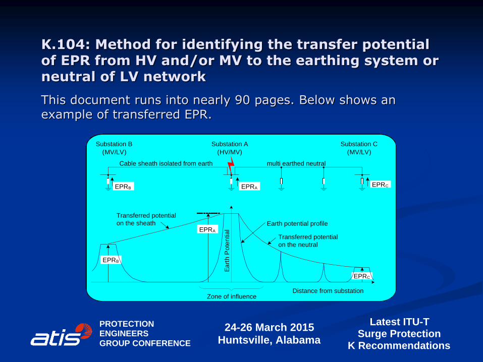
This document runs into nearly 90 pages. Below shows an example of transferred EPR.
24-26 March 2015Huntsville, Alabama
PROTECTIONENGINEERSGROUP CONFERENCE
Latest ITU-TSurge Protection
K Recommendations
Earth potential profile
Transferred potential
on the neutral
Distance from substation
Ea
rth
Po
ten
tia
l
Zone of influence
multi earthed neutralCable sheath isolated from earth
EPRA
EPRB
EPRC
Transferred potential
on the sheath
EPRAEPRBEPRC
Substation A
(HV/MV)
Substation B
(MV/LV)
Substation C
(MV/LV)
K.105: Lightning protection of photovoltaic power supply system feeding a radio base station
Not freely available: Consented (12/2014) in approval and editing
Summary: This Recommendation addresses the lightning protection of a solar photovoltaic power supply system feeding a Radio Base Station. The purpose of this Recommendation is to give guidance on the earthing, bonding and protection of the photovoltaic power supply system feeding Radio Base Station.
24-26 March 2015Huntsville, Alabama
PROTECTIONENGINEERSGROUP CONFERENCE
Latest ITU-TSurge Protection
K Recommendations
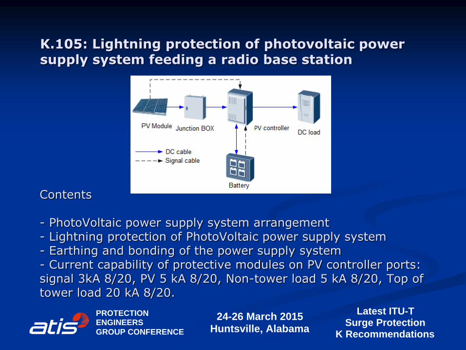
Contents - PhotoVoltaic power supply system arrangement - Lightning protection of PhotoVoltaic power supply system - Earthing and bonding of the power supply system - Current capability of protective modules on PV controller ports: signal 3kA 8/20, PV 5 kA 8/20, Non-tower load 5 kA 8/20, Top of tower load 20 kA 8/20.
24-26 March 2015Huntsville, Alabama
PROTECTIONENGINEERSGROUP CONFERENCE
Latest ITU-TSurge Protection
K Recommendations
K.105: Lightning protection of photovoltaic power supply system feeding a radio base station
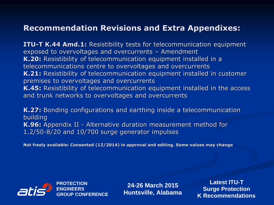
Recommendation Revisions and Extra Appendixes: ITU-T K.44 Amd.1: Resistibility tests for telecommunication equipment exposed to overvoltages and overcurrents – Amendment K.20: Resistibility of telecommunication equipment installed in a telecommunications centre to overvoltages and overcurrents K.21: Resistibility of telecommunication equipment installed in customer premises to overvoltages and overcurrents K.45: Resistibility of telecommunication equipment installed in the access and trunk networks to overvoltages and overcurrents K.27: Bonding configurations and earthing inside a telecommunication building K.96: Appendix II - Alternative duration measurement method for 1.2/50-8/20 and 10/700 surge generator impulses Not freely available: Consented (12/2014) in approval and editing. Some values may change
24-26 March 2015Huntsville, Alabama
PROTECTIONENGINEERSGROUP CONFERENCE
Latest ITU-TSurge Protection
K Recommendations
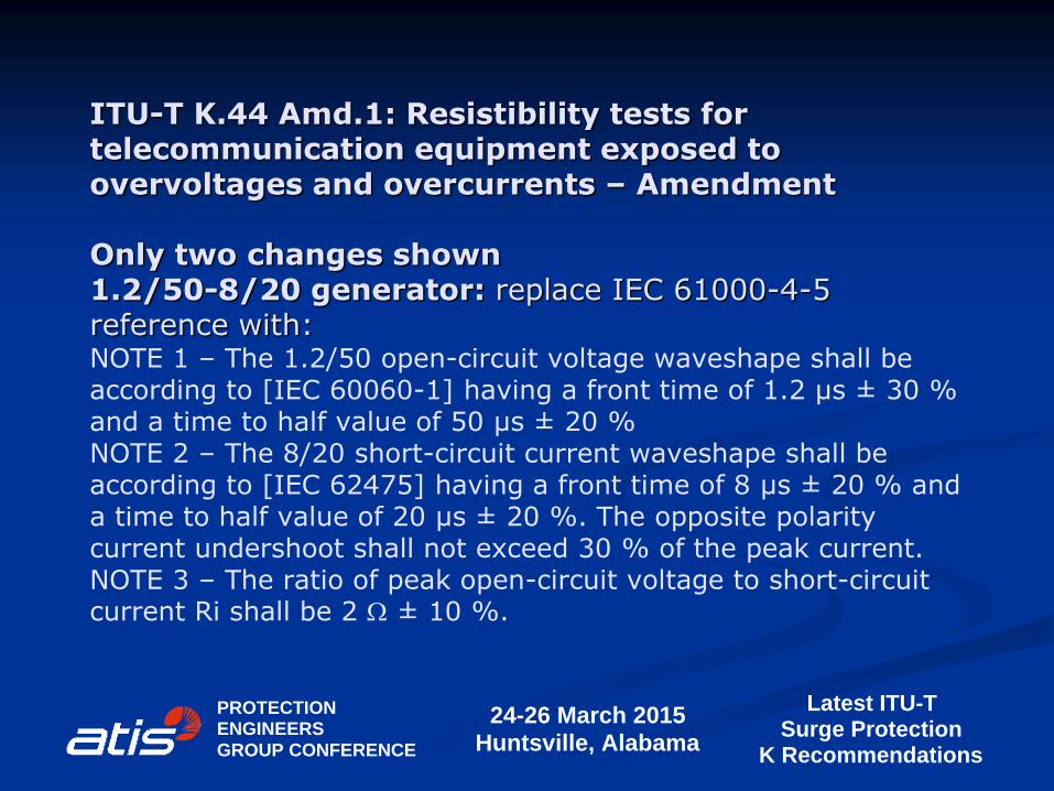
ITU-T K.44 Amd.1: Resistibility tests for telecommunication equipment exposed to overvoltages and overcurrents – Amendment Only two changes shown 1.2/50-8/20 generator: replace IEC 61000-4-5 reference with: NOTE 1 – The 1.2/50 open-circuit voltage waveshape shall be according to [IEC 60060-1] having a front time of 1.2 µs ± 30 % and a time to half value of 50 µs ± 20 % NOTE 2 – The 8/20 short-circuit current waveshape shall be according to [IEC 62475] having a front time of 8 µs ± 20 % and a time to half value of 20 µs ± 20 %. The opposite polarity current undershoot shall not exceed 30 % of the peak current. NOTE 3 – The ratio of peak open-circuit voltage to short-circuit current Ri shall be 2 W ± 10 %.
24-26 March 2015Huntsville, Alabama
PROTECTIONENGINEERSGROUP CONFERENCE
Latest ITU-TSurge Protection
K Recommendations

ITU-T K.44 Amd.1: Resistibility tests for telecommunication equipment exposed to overvoltages and overcurrents – Amendment
24-26 March 2015Huntsville, Alabama
PROTECTIONENGINEERSGROUP CONFERENCE
Latest ITU-TSurge Protection
K Recommendations
Add: Figure A.6.7-3a – Ethernet port longitudinal/common
mode withstand test circuit
1.2/50-8/20
combination
wave generator
Power
Port
EUT
Generator return/Earth
ScreenOther PortsE
ba c d
EUT
reference bar
Termination &
Decoupling
7
5
4
6
3
2
8
1
Ethernet
Port
5 ohm

K.20: Resistibility of telecommunication equipment installed in a telecommunications centre to overvoltages and overcurrents Add: test requirements for UTP Ethernet DM (pair) 600 V/1.5 kV, 1.2/50-8/20, 10 W
CM 2.5 kV/6 kV, 1.2/50-8/20, 5 W test requirements for STP Ethernet 2.5 kV/6 kV, 1.2/50-8/20, 10 W test requirements for PoE DM (inter-pair) 600 V/1.5 kV, 1.2/50-8/20, 10 W
STP shield testing 2.5 kV/6 kV, 1.2/50-8/20, 10 W
24-26 March 2015Huntsville, Alabama
PROTECTIONENGINEERSGROUP CONFERENCE
Latest ITU-TSurge Protection
K Recommendations

K.21: Resistibility of telecommunication equipment installed in customer premises to overvoltages and overcurrents Add: test requirements for UTP Ethernet DM (pair) 600 V/1.5 kV, 1.2/50-8/20, 10 W
CM 2.5 kV/6 kV, 1.2/50-8/20, 5 W test requirements for STP Ethernet 2.5 kV/6 kV, 1.2/50-8/20, 10 W test requirements for PoE DM (inter-pair) 600 V/1.5 kV, 1.2/50-8/20, 10 W
STP shield testing 2.5 kV/6 kV, 1.2/50-8/20, 10 W
24-26 March 2015Huntsville, Alabama
PROTECTIONENGINEERSGROUP CONFERENCE
Latest ITU-TSurge Protection
K Recommendations

K.45: Resistibility of telecommunication equipment installed in the access and trunk networks to overvoltages and overcurrents Add: test requirements for UTP Ethernet DM (pair) 600 V/1.5 kV, 1.2/50-8/20, 10 W
CM 2.5 kV/6 kV, 1.2/50-8/20, 5 W test requirements for STP Ethernet 2.5 kV/6 kV, 1.2/50-8/20, 10 W test requirements for PoE DM (inter-pair) 600 V/1.5 kV, 1.2/50-8/20, 10 W
STP shield testing 2.5 kV/6 kV, 1.2/50-8/20, 10 W
24-26 March 2015Huntsville, Alabama
PROTECTIONENGINEERSGROUP CONFERENCE
Latest ITU-TSurge Protection
K Recommendations
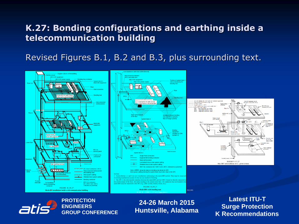
K.27: Bonding configurations and earthing inside a telecommunication building Revised Figures B.1, B.2 and B.3, plus surrounding text.
24-26 March 2015Huntsville, Alabama
PROTECTIONENGINEERSGROUP CONFERENCE
Latest ITU-TSurge Protection
K Recommendations
Recommendation K.27 (05/96) 15
PE
T0506060-92/d05
L1 L2 L3 N PE
PE
Floor
Support column of thebuilding Reinforcement
400 V DC equipment
Bonding ring conductor
System block 1Mesh-BN equipment
Interconnection
Bonding mat
Interconnectedreinforcement
Mesh-BNequipment
48 V dcservice panel
Frame of dcpowerplant
Plumbing
Aircon
AC distribution
System block 2
mesh-BN equipment
Main earthing terminal
To foundationreinforcement/ring
conductor
To earthelectrode
Telecomcables
Basement
Lower floor
Floor n
Floor n+1
DC return conductor (+48 V)
Interconnected reinforcementand building steel
Intra-system cabling
Shielded inter-system cabling
Bonding conductor
FIGURE B.1/K.27
Mesh-BN installation inside a telecommunication building
Bonding ring conductor(recommended)
Connection of cable shieldto the rack is recommended
FIG
URE B.1/K.27.....[D05] = 23.5 cm (page pleine)
400 V DC power supply
400 V dc conductor
(for +200 V and -200 V,
indicated as potential)
Recommendation K.27 (05/96) 17
T0505750-90/d06
Interconnection betweenSPC1 and cable duct
SPC3
SPC2
Frames of system block 1interconnected by thebonding mat
Floor
Bonding mat 1
Connection of cable screento the frame is recommended
SPC1
Steel reinforcementof the floor
System block 3
Insulation between bonding
mat and CBN to prevent
flow of foreign currents
Existingequipment
installed on CBN(system 4)
System block 2
Equipotential bonding conductor
Steel reinforcement
Unshielded intra-or inter-system cabling
Shielded intra-or inter-system cabling
400 V dc conductor (for +200 V and -200 V, indicated as potential)
Inter-system cabling entering the system block must enter close to the SPC
Dots ( ) along the edge at a bonding mat denote its SPC
NOTES
1 System blocks 1, 2 and 3 are new installations conforming to the mesh-IBN method. They may be connected
to existing installations (system 4) that use any method of bonding.
FIGURE B.2/K.27
Mesh-IBN with bonding mat
Single Point Connection
2 The SPC is the only metallic interface between the mesh-IBN and the CBN. It must be directly connected to
the reinforcement of the floor. All cables leading to the system enter here. All conductors that are bonded to themesh-IBN must be connected to the SPC (e.g. cable screens, battery return, etc.).
Low impedance cable duct (CBN Element)
SPC
FIGURE
B.2/K.27.....[D06] = 22.5 cm (page pleine)
400 V DC power supply
400 V DC equipment

K.96: Appendix II - Alternative duration measurement method for 1.2/50-8/20 and 10/700 surge generator impulses Summary The time to half value of a double exponential surge, simulating a lightning impulse, is traditionally measured from a virtual zero point to the 50% amplitude decay point of the waveform, as explained in Appendix I, I.3. The time duration of Electrostatic Discharge (ESD) and Electrical Fast Transient (EFT) impulses is measured as the time for which the impulse exceeds the 50 % amplitude level. The time measured from virtual zero will always be longer than the time between the two waveform 50 % points. Edition 3 of IEC 61000-4-5 (2014) departs from the traditional lightning surge time to half value measurement by specifying the use of the time between the two waveform 50 % points for the 1.2/50-8/20 and 10/700 surge generator waveforms. Amendment 1 to Recommendation ITU-T K.96 introduces Appendix II, which discusses the time value changes caused by the Edition 3 approach and how other standards can be referenced to maintain the tradition measurement method. More details on the change can be found here.
24-26 March 2015Huntsville, Alabama
PROTECTIONENGINEERSGROUP CONFERENCE
Latest ITU-TSurge Protection
K Recommendations
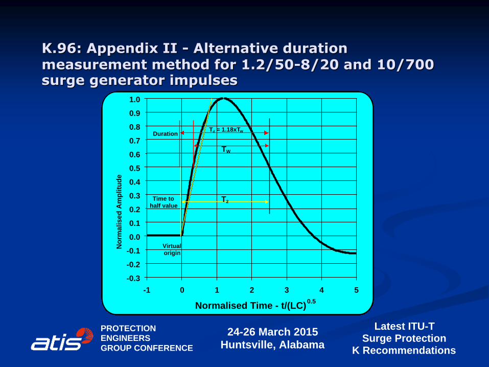
K.96: Appendix II - Alternative duration measurement method for 1.2/50-8/20 and 10/700 surge generator impulses
24-26 March 2015Huntsville, Alabama
PROTECTIONENGINEERSGROUP CONFERENCE
Latest ITU-TSurge Protection
K Recommendations
Normalised Time - t/(LC)0.5
0 1 2 3 4 5
No
rma
lis
ed
Am
pli
tud
e
-0.3
-0.2
-0.1
0.1
0.2
0.3
0.4
0.6
0.7
0.8
0.9
0.0
0.5
1.0
-1
WT
Td = 1.18xTW
Virtualorigin
Duration
Time tohalf value
T2
Latest ITU-T Recommendations K series: Protection against interference (SG5, WP1, Q2-Q5)
24-26 March 2015Huntsville, Alabama
PROTECTIONENGINEERSGROUP CONFERENCE
Latest ITU-TSurge Protection
K Recommendations
This presentation has described • nine new Recommendations, • four revised Recommendations, • one Amendment and • one new Appendix. The document topics reflect the ITU-T WP1 members interest in equipment resistibility requirements, Ethernet, distributed base stations, surge protective components and earthing & bonding. Mick Maytum Email: [email protected] Website: http://pes-spdc.org/