Embed Size (px)
Citation preview
Technical Specification MEF 46.0
Latching Loopback Protocol and Functionality
MEF 46.0 © The Metro Ethernet Forum 2014. Any reproduction of this document, or any portion thereof, shall contain the following statement: "Reproduced with permission of the Metro Ethernet Forum." No user of this document is authorized to modify any of the information contained herein.
Disclaimer
The information in this publication is freely available for reproduction and use by any recipient and is believed to be accurate as of its publication date. Such information is subject to change without notice and the Metro Ethernet Forum (MEF) is not responsible for any errors. The MEF does not assume responsibility to update or correct any information in this publication. No repre-sentation or warranty, expressed or implied, is made by the MEF concerning the completeness, accuracy, or applicability of any information contained herein and no liability of any kind shall be assumed by the MEF as a result of reliance upon such information.
The information contained herein is intended to be used without modification by the recipient or user of this document. The MEF is not responsible or liable for any modifications to this docu-ment made by any other party.
The receipt or any use of this document or its contents does not in any way create, by implication or otherwise:
• any express or implied license or right to or under any patent, copyright, trademark or trade secret rights held or claimed by any MEF member company which are or may be associated with the ideas, techniques, concepts or expressions contained herein; nor
• any warranty or representation that any MEF member companies will announce any product(s) and/or service(s) related thereto, or if such announcements are made, that such announced product(s) and/or service(s) embody any or all of the ideas, technologies, or concepts contained herein; nor
• any form of relationship between any MEF member companies and the recipient or user of this document.
Implementation or use of specific Metro Ethernet standards or recommendations and MEF speci-fications will be voluntary, and no company shall be obliged to implement them by virtue of par-ticipation in the Metro Ethernet Forum. The MEF is a non-profit international organization ac-celerating industry cooperation on Metro Ethernet technology. The MEF does not, expressly or otherwise, endorse or promote any specific products or services.
© The Metro Ethernet Forum 2014. All Rights Reserved.
MEF 46.0 © The Metro Ethernet Forum 2014. Any reproduction of this document, or any portion thereof, shall contain the following statement: "Reproduced with permission of the Metro Ethernet Forum." No user of this document is authorized to modify any of the information contained herein.
Table of Contents 1. List of Contributing Members .............................................................................................. 1
2. Abstract ................................................................................................................................... 1
3. Terms and Acronyms ............................................................................................................ 1
4. Scope........................................................................................................................................ 7
5. Compliance Levels ................................................................................................................. 7
6. Network Reference Model and Use Cases ........................................................................... 8
6.1 Ethernet Test Equipment that can Generate Latching Loopback Requests ....................... 8 6.2 Devices That Can Respond to Latching Loopback Requests ............................................ 9 6.3 UNI to UNI Use Case ........................................................................................................ 9 6.4 ENNI to UNI Use Case ................................................................................................... 10 6.5 UNI to ENNI Use Case ................................................................................................... 11 6.6 ENNI to ENNI Use Case ................................................................................................. 12
7. Functional Requirements .................................................................................................... 13
7.1 Latching Loopback State Machine .................................................................................. 13 Latching Loopback State Machine Overview ....................................................................... 18 7.1.1 Latching Loopback State Machine Variables ....................................................................... 19 7.1.2 Latching Loopback State Machine Events ............................................................................ 19 7.1.3 Latching Loopback State Machine Actions .......................................................................... 21 7.1.4 Latching Loopback State Machine Transitions ..................................................................... 22 7.1.5
7.2 Operation of Latching Loopback ..................................................................................... 24 7.3 Latching Loopback Requirements ................................................................................... 28
Latching Loopback Provisioning .......................................................................................... 28 7.3.1 Latching Loopback Prohibited State ..................................................................................... 29 7.3.2 Latching Loopback Inactive State ......................................................................................... 29 7.3.3 Latching Loopback Active State ........................................................................................... 29 7.3.4
8. Message Protocol .................................................................................................................. 33
8.1 Overview ......................................................................................................................... 33 8.2 Message Interchange Diagrams ....................................................................................... 33
Discovery .............................................................................................................................. 33 8.2.1 State Verification .................................................................................................................. 34 8.2.2 Loopback Activation and Deactivation ................................................................................. 35 8.2.3 Latching Loopback Protocol Resiliency ............................................................................... 36 8.2.4
8.3 Protocol Syntax................................................................................................................ 36 MEL ...................................................................................................................................... 38 8.3.1 Version .................................................................................................................................. 38 8.3.2 OpCode ................................................................................................................................. 38 8.3.3 Flags ...................................................................................................................................... 38 8.3.4
8.3.4.1 Loopback Status ................................................................................................................. 38 8.3.4.2 Loopback Direction ........................................................................................................... 39 8.3.4.3 Unrecognized TLV ............................................................................................................. 39
TLV Offset ............................................................................................................................ 39 8.3.5 Message Type ........................................................................................................................ 39 8.3.6 Response Code ...................................................................................................................... 40 8.3.7
MEF 46.0 © The Metro Ethernet Forum 2014. Any reproduction of this document, or any portion thereof, shall contain the following statement: "Reproduced with permission of the Metro Ethernet Forum." No user of this document is authorized to modify any of the information contained herein.
Page i
Loopback Port MAC Address ............................................................................................... 42 8.3.8 TLVs ..................................................................................................................................... 42 8.3.9
8.3.9.1 Expiration Timer TLV ........................................................................................................ 44 End TLV ................................................................................................................................ 44 8.3.10
9. References ............................................................................................................................. 45
Appendix A Latching Loopback Protocol Resiliency (Informative) ................................. 46 A.1 Loopback State Enquiry ........................................................................................................................ 46 A.2 Loopback Activate ................................................................................................................................ 47 A.3 Loopback Deactivate ............................................................................................................................. 48 A.4 Loopback Expiration Time .................................................................................................................... 48
MEF 46.0 © The Metro Ethernet Forum 2014. Any reproduction of this document, or any portion thereof, shall contain the following statement: "Reproduced with permission of the Metro Ethernet Forum." No user of this document is authorized to modify any of the information contained herein.
Page ii
List of Figures Figure 1 – Test Equipment that Can Send Latching Loopback Requests ....................................... 8 Figure 2 – Devices that Can Respond to Latching Loopback Requests ......................................... 9 Figure 3 – UNI to UNI Loopback Use Case ................................................................................. 10 Figure 4 – ENNI to UNI Loopback Use Case .............................................................................. 11 Figure 5 – UNI to ENNI Loopback Use Case .............................................................................. 11 Figure 6 – ENNI to ENNI Loopback Use Case ............................................................................ 12 Figure 7 – Latching Loopback State Machine Diagram ............................................................... 14 Figure 8 – Latching Loopback State Machine Transitions ........................................................... 15 Figure 9 – Latching Loopback Function Location ....................................................................... 16 Figure 10 – Example of ESCF Tag Manipulation ........................................................................ 17 Figure 11 – Latching Loopback Active: Detailed Connections and Terminology ....................... 26 Figure 12 – External Loopback..................................................................................................... 27 Figure 13 – Latching Loopback Details for a Multipoint Service Mapped at 3-ports .................. 32 Figure 14 – Discovery Message Interchange ................................................................................ 34 Figure 15 – State Verification Message Interchange .................................................................... 35 Figure 16 – Loopback Activation Message Interchange .............................................................. 36 Figure 17 – Generic LL PDU Format ........................................................................................... 37 Figure 18 – Latching Loopback TLV Format ............................................................................... 42 Figure 19 – Expiration Timer TLV format ................................................................................... 44
MEF 46.0 © The Metro Ethernet Forum 2014. Any reproduction of this document, or any portion thereof, shall contain the following statement: "Reproduced with permission of the Metro Ethernet Forum." No user of this document is authorized to modify any of the information contained herein.
Page iii
List of Tables Table 1 – Terms and Acronyms ...................................................................................................... 6 Table 2 – Flag Field Definitions ................................................................................................... 38 Table 3 – Latching Loopback Control Message Types ................................................................ 39 Table 4 – MEP Control Message Response Codes ....................................................................... 41 Table 5 – Latching Loopback TLV Subtypes ............................................................................... 43
MEF 46.0 © The Metro Ethernet Forum 2014. Any reproduction of this document, or any portion thereof, shall contain the following statement: "Reproduced with permission of the Metro Ethernet Forum." No user of this document is authorized to modify any of the information contained herein.
Page iv
Latching Loopback Protocol and Functionality
1. List of Contributing Members
The following members of the MEF participated in the development of this document and have requested to be included in this list.
Adva Optical Networking SE Comcast Albis Technologies Embratel Alcatel Lucent EXFO Inc AT&T Level 3 Broadcom JDSU Calix Microsemi Carrier Ethernet Academy Omnitron Systems Technology, Inc. Coriant RAD Data Communications Ceragon Networks Time Warner Cable China Telecom Transition Networks Ciena Corporation Verizon Business Cisco Systems
2. Abstract
This specification describes the use cases, functionality and protocol for a Latching Loopback feature in Ethernet Equipment. Latching Loopback can be controlled to return selected Ethernet frames in the direction from which they came.
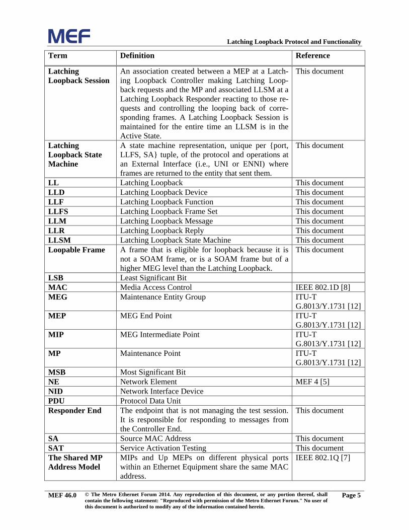
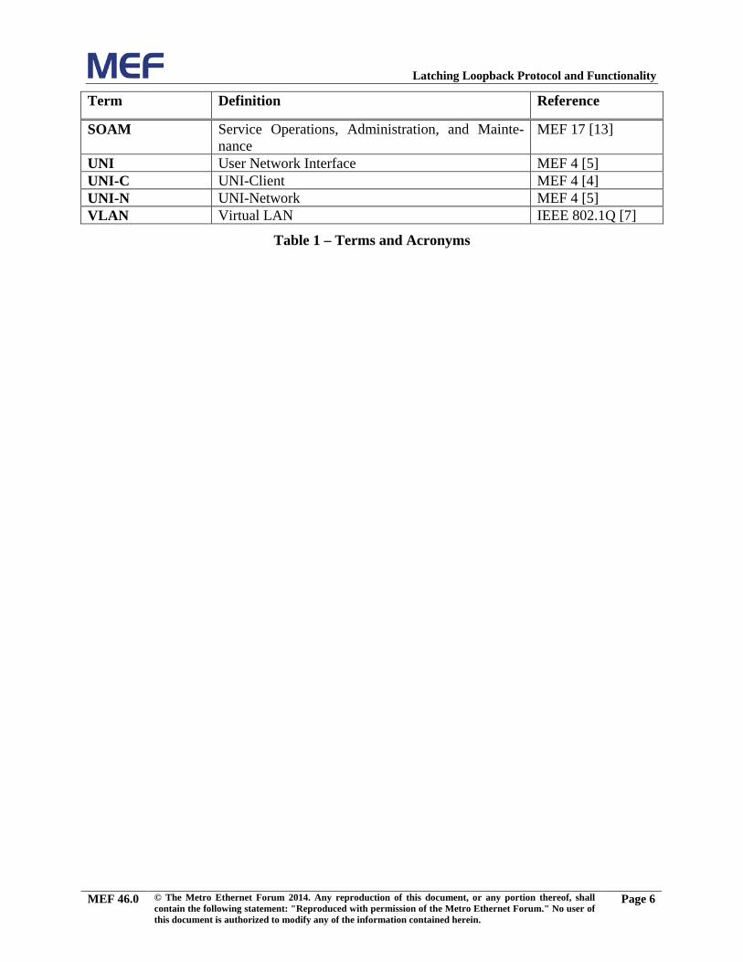
3. Terms and Acronyms
This section defines the terms used in this document. In many cases, the normative definitions to terms are found in other documents. In these cases, the third column is used to provide the refer-ence that is controlling, in other MEF or external documents.
Term Definition Reference
CEN Carrier Ethernet Network MEF 12.2 [6] Controller End The endpoint that manages control procedures for
tests such as SAT or Latching Loopback. It is re-sponsible for initiating test session(s) and reporting results of the test session(s).
This document
DA Destination MAC Address This document
EI External Interface MEF 4 [5]
ENNI External Network Network Interface MEF 4 [5]
ESCF ETH Subscriber Conditioning Function MEF 12.2 [6]
MEF 46.0 © The Metro Ethernet Forum 2014. Any reproduction of this document, or any portion thereof, shall contain the following statement: "Reproduced with permission of the Metro Ethernet Forum." No user of this document is authorized to modify any of the information contained herein.
Page 1
Latching Loopback Protocol and Functionality
Term Definition Reference
ETE Ethernet Test Equipment This document ETE-A Ethernet Test Equipment-Application This document ETE-I Ethernet Test Equipment-Instrument This document
ETE-TH Ethernet Test Equipment-Test Head This document
ETH Ethernet Services Layer MEF 4 [5]
Ethernet Equipment
A Network Element or Ethernet Test Equipment, with ETH functions, installed or used in a CEN.
This document
Ethernet Subscriber Conditioning Function
The Ethernet Subscriber Conditioning Function (ESCF) is the processing entity responsible for clas-sification, filtering, metering, marking, policing, scheduling, shaping and, in general, conditioning the subscriber flow into and out of a UNI-N.
MEF 12.2 [6]
Ethernet Test Equipment
A general term to include an Ethernet Test Equip-ment-Application, Ethernet Test Equipment-Test Head, and/or Ethernet Test Equipment-Instrument.
This document
Ethernet Test Equipment-Application
Functionality resident in a Network Element which may include a Generator Test Function, a Collector Test Function, and/or Latching Loopback Function that enables the Network Element to perform Ser-vice Activation Testing and activate/deactivate loopback devices.
This document
Ethernet Test Equipment-Instrument
A portable, external Ethernet testing equipment not permanently installed in the network, which may include a Generator Test Function, a Collector Test Function, and/or Latching Loopback Function that enables the ETE to perform Service Activation Testing and activate/deactivate loopback devices.
This document
Ethernet Test Equipment-Test Head
An external Ethernet testing equipment permanent-ly installed in the network, which may include a Generator Test Function, a Collector Test Function, and/or Latching Loopback Function that enables the ETE to perform Service Activation Testing and ac-tivate/deactivate loopback devices. It is not in-volved in the forwarding path of services.
This document
ETSS Ethernet Test Support System This document
MEF 46.0 © The Metro Ethernet Forum 2014. Any reproduction of this document, or any portion thereof, shall contain the following statement: "Reproduced with permission of the Metro Ethernet Forum." No user of this document is authorized to modify any of the information contained herein.
Page 2
Latching Loopback Protocol and Functionality
Term Definition Reference
Ethernet Test Support System
A function that coordinates test activity at Ethernet Test Equipment or Network Elements.
This document
External Interface A User-Network Interface (UNI) or an External Network Network Interface.
MEF 4 [5]
External Loopback
For an LLF at an EI located at the boundary be-tween a CEN and an External Network, a loopback where frames received at the EI from the External Network are looped back out through the same EI towards the External Network.
This document
External Network The network connected to an EI; that is: • the network containing the UNI-N if the EI
is a UNI-C • the network containing the UNI-C if the EI
is a UNI-N • the network containing the peer ENNI-N if
the EI is an ENNI-N
This document
FCS Frame Check Sequence IEEE 802.1Q [7] Individual MP Address Model
Each MP in an Ethernet Equipment has the MAC address of the underlying physical port; i.e., MPs on different physical ports have different MAC ad-dresses.
IEEE 802.1Q [7]
Information Rate The average bit rate of Ethernet service frames at the measurement point starting with the first MAC address bit and ending with the last FCS bit.
ITU-T Y.1564 [10]
Internal Loopback For an LLF at an EI located at the boundary be-tween a CEN and an External Network, a loopback where frames received at the EI from within the CEN are looped back towards the CEN.
This document
Latching Loopback Controller
The Controller End ETE MEP that initiates a Latch-ing Loopback Session and which sends LLMs to a Latching Loopback Responder.
This document
Latching Loopback Control Message
Either a Latching Loopback Message or a Latching Loopback Reply.
This document
Latching Loopback Device
Any Network Element or Ethernet Test Equipment which acts as Latching Loopback Responder and supports the Latching Loopback Function and pro-tocol defined in this specification.
This document
MEF 46.0 © The Metro Ethernet Forum 2014. Any reproduction of this document, or any portion thereof, shall contain the following statement: "Reproduced with permission of the Metro Ethernet Forum." No user of this document is authorized to modify any of the information contained herein.
Page 3
Latching Loopback Protocol and Functionality
Term Definition Reference
Latching Loopback Frame Set
A set of frames identified at an LLF within a partic-ular EI by containing the same CE-VLAN ID and/or S-VLAN ID, or by being untagged; that is, that fall into one of the following five cases1: a) untagged; or b) containing a C-tag with a particular CE-VLAN
ID at a UNI, and not containing an S-tag; or c) containing an S-tag with a particular S-VLAN
ID at an ENNI that does not have a VUNI as-sociated with that S-VLAN ID , or at an ENNI that has a VUNI associated with that S-VLAN ID if the frame is received over the ENNI; or
d) containing an S-tag with a particular S-VLAN ID at an ENNI that has a VUNI associated with that S-VLAN ID, and not containing a C-tag; or
e) containing an S-tag with a particular S-VLAN ID at an ENNI that has a VUNI associated with that S-VLAN ID, and containing a C-tag with a particular CE-VLAN ID.
Latching Loopback Control Messages may be con-sumed by a MP and hence not pass though the LLF; however, they are considered to belong to an LLFS according to the tags they would have when passing through the LLF, if the consuming MP did not ex-ist.
This document
Latching Loopback Function
The collection of all Latching Loopback State Ma-chines and associated functionality for a given port.
This document
Latching Loopback Message
A PDU sent from a Latching Loopback Controller to a Latching Loopback Responder.
This document
Latching Loopback Reply
A PDU sent from a Latching Loopback Responder to a Latching Loopback Controller, usually in re-sponse to a Latching Loopback Message.
This document
Latching Loopback Responder
The Responder End MP that implements a Latching Loopback Session and which sends LLRs to a Latching Loopback Controller.
This document
1 An S-tagged frame arriving at an ENNI that has a VUNI for that S-VID could belong to two LLFSs, one matching just the S-tag at the ENNI (case c), and one matching both the S-tag and the C-tag if any at the VUNI (case d or e).
MEF 46.0 © The Metro Ethernet Forum 2014. Any reproduction of this document, or any portion thereof, shall contain the following statement: "Reproduced with permission of the Metro Ethernet Forum." No user of this document is authorized to modify any of the information contained herein.
Page 4
Latching Loopback Protocol and Functionality
Term Definition Reference
Latching Loopback Session
An association created between a MEP at a Latch-ing Loopback Controller making Latching Loop-back requests and the MP and associated LLSM at a Latching Loopback Responder reacting to those re-quests and controlling the looping back of corre-sponding frames. A Latching Loopback Session is maintained for the entire time an LLSM is in the Active State.
This document
Latching Loopback State Machine
A state machine representation, unique per {port, LLFS, SA} tuple, of the protocol and operations at an External Interface (i.e., UNI or ENNI) where frames are returned to the entity that sent them.
This document
LL Latching Loopback This document LLD Latching Loopback Device This document LLF Latching Loopback Function This document LLFS Latching Loopback Frame Set This document LLM Latching Loopback Message This document LLR Latching Loopback Reply This document LLSM Latching Loopback State Machine This document Loopable Frame A frame that is eligible for loopback because it is
not a SOAM frame, or is a SOAM frame but of a higher MEG level than the Latching Loopback.
This document
LSB Least Significant Bit MAC Media Access Control IEEE 802.1D [8] MEG Maintenance Entity Group ITU-T
G.8013/Y.1731 [12] MEP MEG End Point ITU-T
G.8013/Y.1731 [12] MIP MEG Intermediate Point ITU-T
G.8013/Y.1731 [12] MP Maintenance Point ITU-T
G.8013/Y.1731 [12] MSB Most Significant Bit NE Network Element MEF 4 [5] NID Network Interface Device PDU Protocol Data Unit Responder End The endpoint that is not managing the test session.
It is responsible for responding to messages from the Controller End.
This document
SA Source MAC Address This document SAT Service Activation Testing This document The Shared MP Address Model
MIPs and Up MEPs on different physical ports within an Ethernet Equipment share the same MAC address.
IEEE 802.1Q [7]
MEF 46.0 © The Metro Ethernet Forum 2014. Any reproduction of this document, or any portion thereof, shall contain the following statement: "Reproduced with permission of the Metro Ethernet Forum." No user of this document is authorized to modify any of the information contained herein.
Page 5
Latching Loopback Protocol and Functionality
Term Definition Reference
SOAM Service Operations, Administration, and Mainte-nance
MEF 17 [13]
UNI User Network Interface MEF 4 [5] UNI-C UNI-Client MEF 4 [4] UNI-N UNI-Network MEF 4 [5] VLAN Virtual LAN IEEE 802.1Q [7]
Table 1 – Terms and Acronyms
MEF 46.0 © The Metro Ethernet Forum 2014. Any reproduction of this document, or any portion thereof, shall contain the following statement: "Reproduced with permission of the Metro Ethernet Forum." No user of this document is authorized to modify any of the information contained herein.
Page 6
Latching Loopback Protocol and Functionality
4. Scope
This specification defines the protocol and functionality for Latching Loopbacks (LLs) for Ser-vice Activation Testing (SAT) and troubleshooting up to the Information Rate for point-to-point and multipoint services across multiple Carrier Ethernet Networks (CENs). The Latching Loop-back Function (LLF) is intended to be implemented in UNI and ENNI locations in various Carri-er Ethernet equipment such as Network Interface Devices (NIDs), bridges, switches, and Ether-net Test Equipment (ETE). Ethernet Equipment that implements the Latching Loopback Func-tion is referred to as a Latching Loopback Device (LLD). The functionality has been developed to be compatible with older test methodologies such as IETF RFC 2544 [9] and newer method-ologies such as ITU Y.1564 [10]. An important characteristic of the loopback is that it leaves the Ethernet frame payload unaltered.
This specification defines Protocol Data Units (PDUs) that control an LLF. There are no special PDU types for LL test packets.
5. Compliance Levels
The key words "MUST", "MUST NOT", "REQUIRED", "SHALL", "SHALL NOT", "SHOULD", "SHOULD NOT", "RECOMMENDED", "MAY", and "OPTIONAL" in this document are to be interpreted as described in RFC 2119 [3]. All key words are presented in up-per case, bold text.
A paragraph preceded by [Rx], where x indicates a sequentially increasing number throughout the document, specifies a mandatory requirement that MUST be followed. A paragraph preceded by [Dy], where y indicates a sequentially increasing number throughout the document, specifies a desired requirement that SHOULD be followed. A paragraph preceded by [Oz], where z indi-cates a sequentially increasing number throughout the document, specifies an optional require-ment that MAY be followed.
MEF 46.0 © The Metro Ethernet Forum 2014. Any reproduction of this document, or any portion thereof, shall contain the following statement: "Reproduced with permission of the Metro Ethernet Forum." No user of this document is authorized to modify any of the information contained herein.
Page 7
Latching Loopback Protocol and Functionality
6. Network Reference Model and Use Cases
The need for Latching Loopback comes from the various use cases that employ the technique. This section discusses various ways that a Latching Loopback can be configured to enable a test session.
6.1 Ethernet Test Equipment that can Generate Latching Loopback Requests
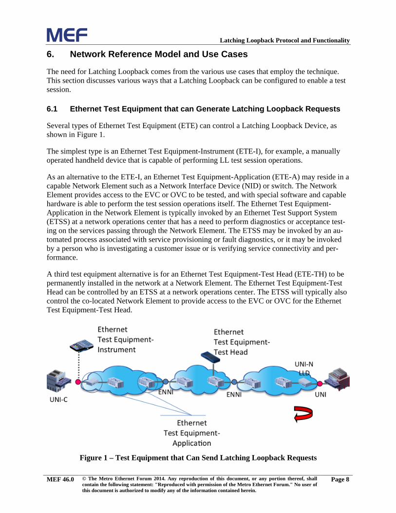
Several types of Ethernet Test Equipment (ETE) can control a Latching Loopback Device, as shown in Figure 1.
The simplest type is an Ethernet Test Equipment-Instrument (ETE-I), for example, a manually operated handheld device that is capable of performing LL test session operations.
As an alternative to the ETE-I, an Ethernet Test Equipment-Application (ETE-A) may reside in a capable Network Element such as a Network Interface Device (NID) or switch. The Network Element provides access to the EVC or OVC to be tested, and with special software and capable hardware is able to perform the test session operations itself. The Ethernet Test Equipment-Application in the Network Element is typically invoked by an Ethernet Test Support System (ETSS) at a network operations center that has a need to perform diagnostics or acceptance test-ing on the services passing through the Network Element. The ETSS may be invoked by an au-tomated process associated with service provisioning or fault diagnostics, or it may be invoked by a person who is investigating a customer issue or is verifying service connectivity and per-formance.
A third test equipment alternative is for an Ethernet Test Equipment-Test Head (ETE-TH) to be permanently installed in the network at a Network Element. The Ethernet Test Equipment-Test Head can be controlled by an ETSS at a network operations center. The ETSS will typically also control the co-located Network Element to provide access to the EVC or OVC for the Ethernet Test Equipment-Test Head.
Figure 1 – Test Equipment that Can Send Latching Loopback Requests
MEF 46.0 © The Metro Ethernet Forum 2014. Any reproduction of this document, or any portion thereof, shall contain the following statement: "Reproduced with permission of the Metro Ethernet Forum." No user of this document is authorized to modify any of the information contained herein.
Page 8
Latching Loopback Protocol and Functionality
It should be noted that all these alternatives are regarded as valid use cases for Latching Loop-back. Although only a single type of test equipment will be shown in most figures, other test equipment alternatives could also be used.
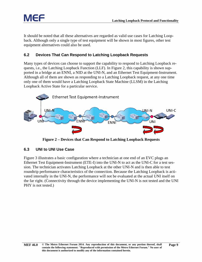
6.2 Devices That Can Respond to Latching Loopback Requests
Many types of devices can choose to support the capability to respond to Latching Loopback re-quests, i.e., the Latching Loopback Function (LLF). In Figure 2, this capability is shown sup-ported in a bridge at an ENNI, a NID at the UNI-N, and an Ethernet Test Equipment-Instrument. Although all of them are shown as responding to a Latching Loopback request, at any one time only one of them would have a Latching Loopback State Machine (LLSM) in the Latching Loopback Active State for a particular service.
Figure 2 – Devices that Can Respond to Latching Loopback Requests
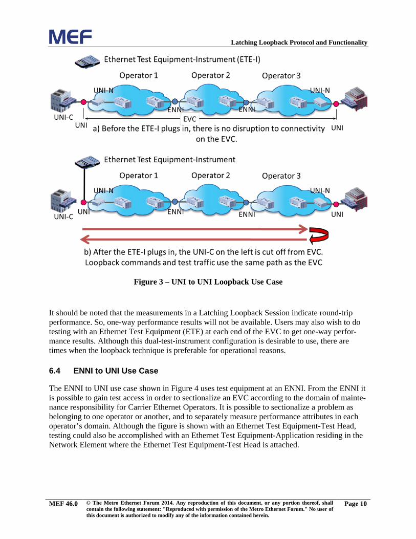
6.3 UNI to UNI Use Case
Figure 3 illustrates a basic configuration where a technician at one end of an EVC plugs an Ethernet Test Equipment-Instrument (ETE-I) into the UNI-N to act as the UNI-C for a test ses-sion. The technician activates Latching Loopback at the other UNI-N and is then able to test roundtrip performance characteristics of the connection. Because the Latching Loopback is acti-vated internally in the UNI-N, the performance will not be evaluated at the actual UNI itself on the far right. (Connectivity through the device implementing the UNI-N is not tested and the UNI PHY is not tested.)
MEF 46.0 © The Metro Ethernet Forum 2014. Any reproduction of this document, or any portion thereof, shall contain the following statement: "Reproduced with permission of the Metro Ethernet Forum." No user of this document is authorized to modify any of the information contained herein.
Page 9
Latching Loopback Protocol and Functionality
Figure 3 – UNI to UNI Loopback Use Case
It should be noted that the measurements in a Latching Loopback Session indicate round-trip performance. So, one-way performance results will not be available. Users may also wish to do testing with an Ethernet Test Equipment (ETE) at each end of the EVC to get one-way perfor-mance results. Although this dual-test-instrument configuration is desirable to use, there are times when the loopback technique is preferable for operational reasons.
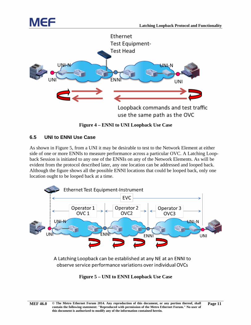
6.4 ENNI to UNI Use Case
The ENNI to UNI use case shown in Figure 4 uses test equipment at an ENNI. From the ENNI it is possible to gain test access in order to sectionalize an EVC according to the domain of mainte-nance responsibility for Carrier Ethernet Operators. It is possible to sectionalize a problem as belonging to one operator or another, and to separately measure performance attributes in each operator’s domain. Although the figure is shown with an Ethernet Test Equipment-Test Head, testing could also be accomplished with an Ethernet Test Equipment-Application residing in the Network Element where the Ethernet Test Equipment-Test Head is attached.
MEF 46.0 © The Metro Ethernet Forum 2014. Any reproduction of this document, or any portion thereof, shall contain the following statement: "Reproduced with permission of the Metro Ethernet Forum." No user of this document is authorized to modify any of the information contained herein.
Page 10
Latching Loopback Protocol and Functionality
Figure 4 – ENNI to UNI Loopback Use Case
6.5 UNI to ENNI Use Case
As shown in Figure 5, from a UNI it may be desirable to test to the Network Element at either side of one or more ENNIs to measure performance across a particular OVC. A Latching Loop-back Session is initiated to any one of the ENNIs on any of the Network Elements. As will be evident from the protocol described later, any one location can be addressed and looped back. Although the figure shows all the possible ENNI locations that could be looped back, only one location ought to be looped back at a time.
Figure 5 – UNI to ENNI Loopback Use Case
MEF 46.0 © The Metro Ethernet Forum 2014. Any reproduction of this document, or any portion thereof, shall contain the following statement: "Reproduced with permission of the Metro Ethernet Forum." No user of this document is authorized to modify any of the information contained herein.
Page 11
Latching Loopback Protocol and Functionality
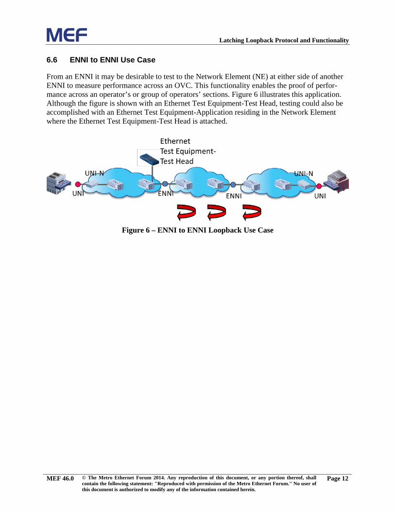
6.6 ENNI to ENNI Use Case
From an ENNI it may be desirable to test to the Network Element (NE) at either side of another ENNI to measure performance across an OVC. This functionality enables the proof of perfor-mance across an operator’s or group of operators’ sections. Figure 6 illustrates this application. Although the figure is shown with an Ethernet Test Equipment-Test Head, testing could also be accomplished with an Ethernet Test Equipment-Application residing in the Network Element where the Ethernet Test Equipment-Test Head is attached.
Figure 6 – ENNI to ENNI Loopback Use Case
MEF 46.0 © The Metro Ethernet Forum 2014. Any reproduction of this document, or any portion thereof, shall contain the following statement: "Reproduced with permission of the Metro Ethernet Forum." No user of this document is authorized to modify any of the information contained herein.
Page 12
Latching Loopback Protocol and Functionality
7. Functional Requirements
Latching Loopback is initiated by a Latching Loopback Controller that provides in-line control of the Latching Loopback State Machine (LLSM) at a Latching Loopback Responder and sup-plies the Ethernet frames to be looped back by the Latching Loopback Responder. Latching Loopback is implemented by a Latching Loopback Responder at an External Interface (EI) in a Latching Loopback Function (LLF), at the boundary between a CEN and an External Network. Latching Loopback is used within a system that consists of the Ethernet Test Equipment (ETE) that acts as a Latching Loopback Controller; the Carrier Ethernet Network (CEN) that forwards the Latching Loopback Messages (LLMs), the Latching Loopback Replies (LLRs), and the Ethernet frames that are looped back; and the Network Element (NE) or ETE acting as a Latch-ing Loopback Responder that incorporates the EI with an LLF. This section details the function-ality and requirements of the elements of this system, with primary focus being on the exact functionality required in the Latching Loopback State Machine (LLSM) to obtain uniformly sat-isfactory results in all modes.
LLMs and LLRs are carried in SOAM frames, as described in section 8. LLMs are transmitted by a MEP at an ETE acting as a Latching Loopback Controller for a Latching Loopback Session, and are received by an MP at an EI where the Latching Loopback Responder implementing the LLSM for that session is located. LLRs are transmitted by the MP at the Latching Loopback Re-sponder and received by the MEP in the Latching Loopback Controller for the associated Latch-ing Loopback Session. The association of MPs with LLSMs is described further in the following section.
7.1 Latching Loopback State Machine
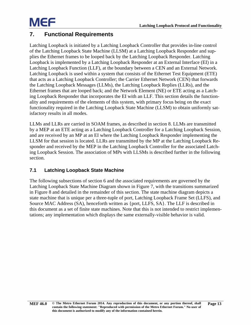
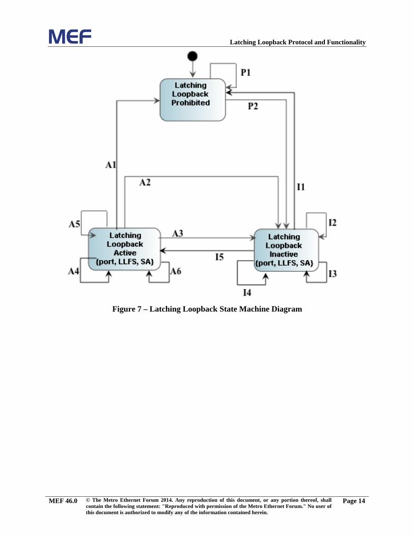
The following subsections of section 6 and the associated requirements are governed by the Latching Loopback State Machine Diagram shown in Figure 7, with the transitions summarized in Figure 8 and detailed in the remainder of this section. The state machine diagram depicts a state machine that is unique per a three-tuple of port, Latching Loopback Frame Set (LLFS), and Source MAC Address (SA), henceforth written as {port, LLFS, SA}. The LLF is described in this document as a set of finite state machines. Note that this is not intended to restrict implemen-tations; any implementation which displays the same externally-visible behavior is valid.
MEF 46.0 © The Metro Ethernet Forum 2014. Any reproduction of this document, or any portion thereof, shall contain the following statement: "Reproduced with permission of the Metro Ethernet Forum." No user of this document is authorized to modify any of the information contained herein.
Page 13
Latching Loopback Protocol and Functionality
Figure 7 – Latching Loopback State Machine Diagram
MEF 46.0 © The Metro Ethernet Forum 2014. Any reproduction of this document, or any portion thereof, shall contain the following statement: "Reproduced with permission of the Metro Ethernet Forum." No user of this document is authorized to modify any of the information contained herein.
Page 14
Latching Loopback Protocol and Functionality
Figure 8 – Latching Loopback State Machine Transitions
Each Latching Loopback is established at a specific LLD port (i.e., an EI) for a specific LLFS identified by the Latching Loopback Activate Request received from an Ethernet Test Equipment (ETE) with a specific SA. The Latching Loopback, and the corresponding LLSM, are thus spe-cific to that {port, LLFS, SA}.
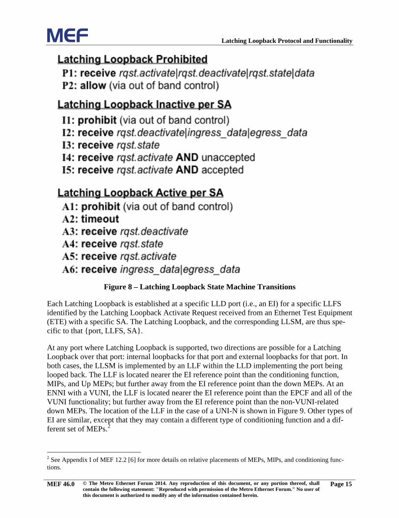
At any port where Latching Loopback is supported, two directions are possible for a Latching Loopback over that port: internal loopbacks for that port and external loopbacks for that port. In both cases, the LLSM is implemented by an LLF within the LLD implementing the port being looped back. The LLF is located nearer the EI reference point than the conditioning function, MIPs, and Up MEPs; but further away from the EI reference point than the down MEPs. At an ENNI with a VUNI, the LLF is located nearer the EI reference point than the EPCF and all of the VUNI functionality; but further away from the EI reference point than the non-VUNI-related down MEPs. The location of the LLF in the case of a UNI-N is shown in Figure 9. Other types of EI are similar, except that they may contain a different type of conditioning function and a dif-ferent set of MEPs.2
2 See Appendix I of MEF 12.2 [6] for more details on relative placements of MEPs, MIPs, and conditioning func-tions.
MEF 46.0 © The Metro Ethernet Forum 2014. Any reproduction of this document, or any portion thereof, shall contain the following statement: "Reproduced with permission of the Metro Ethernet Forum." No user of this document is authorized to modify any of the information contained herein.
Page 15
Latching Loopback Protocol and Functionality
Figure 9 – Latching Loopback Function Location
An External Loopback acts on frames received at the EI from the External Network – that is, from the UNI-C in the case of a UNI-N, from the UNI-N in the case of a UNI-C, or from the peer ENNI-N in the case of an ENNI-N. Loopable Frames that match the SA and LLFS for which the loopback has been activated are looped back out of the same EI, without passing through the conditioning function. (Frames that do not match the {port. LLFS, SA} are handled normally.)
An Internal Loopback acts on frames received at the EI from the CEN – that is, frames that would have been transmitted out of the EI if the loopback was not active. Frames that match the SA and LLFS for which the loopback has been activated pass through the egress conditioning function, are looped back towards the CEN, and then pass through the ingress conditioning func-tion.
Note: An Internal Loopback at a UNI-C is not defined.
An ETE-I might not contain a conditioning function and might not have the capability of for-warding frames between different ports, i.e., of forming part of a CEN. Such devices can only support External Loopback.
As described previously, the LLF instantiates a separate instance of the LLSM per tuple of {port, LLFS, SA}3. An LLSM for a given {port, LLFS, SA} is associated with the Maintenance Points
3 Therefore looping an EVC that maps to multiple VLAN IDs requires multiple state machines.
MEF 46.0 © The Metro Ethernet Forum 2014. Any reproduction of this document, or any portion thereof, shall contain the following statement: "Reproduced with permission of the Metro Ethernet Forum." No user of this document is authorized to modify any of the information contained herein.
Page 16
Latching Loopback Protocol and Functionality
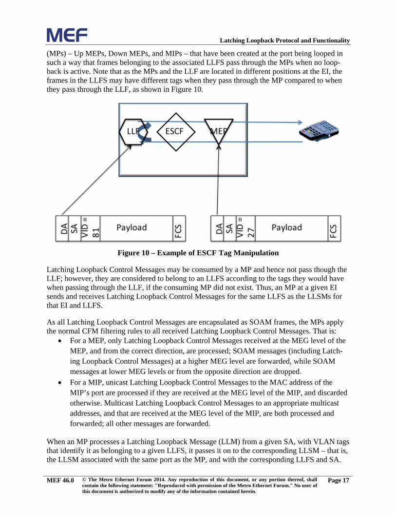
(MPs) – Up MEPs, Down MEPs, and MIPs – that have been created at the port being looped in such a way that frames belonging to the associated LLFS pass through the MPs when no loop-back is active. Note that as the MPs and the LLF are located in different positions at the EI, the frames in the LLFS may have different tags when they pass through the MP compared to when they pass through the LLF, as shown in Figure 10.
Figure 10 – Example of ESCF Tag Manipulation
Latching Loopback Control Messages may be consumed by a MP and hence not pass though the LLF; however, they are considered to belong to an LLFS according to the tags they would have when passing through the LLF, if the consuming MP did not exist. Thus, an MP at a given EI sends and receives Latching Loopback Control Messages for the same LLFS as the LLSMs for that EI and LLFS.
As all Latching Loopback Control Messages are encapsulated as SOAM frames, the MPs apply the normal CFM filtering rules to all received Latching Loopback Control Messages. That is:
• For a MEP, only Latching Loopback Control Messages received at the MEG level of the MEP, and from the correct direction, are processed; SOAM messages (including Latch-ing Loopback Control Messages) at a higher MEG level are forwarded, while SOAM messages at lower MEG levels or from the opposite direction are dropped.
• For a MIP, unicast Latching Loopback Control Messages to the MAC address of the MIP’s port are processed if they are received at the MEG level of the MIP, and discarded otherwise. Multicast Latching Loopback Control Messages to an appropriate multicast addresses, and that are received at the MEG level of the MIP, are both processed and forwarded; all other messages are forwarded.
When an MP processes a Latching Loopback Message (LLM) from a given SA, with VLAN tags that identify it as belonging to a given LLFS, it passes it on to the corresponding LLSM – that is, the LLSM associated with the same port as the MP, and with the corresponding LLFS and SA.
MEF 46.0 © The Metro Ethernet Forum 2014. Any reproduction of this document, or any portion thereof, shall contain the following statement: "Reproduced with permission of the Metro Ethernet Forum." No user of this document is authorized to modify any of the information contained herein.
Page 17
Latching Loopback Protocol and Functionality
Note that there may be more than one MP on a port that passes received LLMs to the same LLSM (e.g., if the MPs are at different MEG levels).
When an LLSM for a given {port, LLFS, SA} sends Latching Loopback Replies (LLRs), it uses the same MP that received the LLM. The MP transmits the LLR using its configured MEG level, with VLAN ID of the corresponding LLM, and in the case of a MIP, in the opposite direction to that in which the LLM was received (i.e., back towards the source of the corresponding LLM).
When an LLSM for a given {port, LLFS, SA} is associated with more than one MP, and the LLSM is in the Loopback Active state, a timer expiration or a management prohibit action caus-es the LLSM to send notification of this using the MP that received the original Loopback Acti-vate request.
Note 1: The port in question could be a physical port or Link Aggregation Group, depending up-on the MP receiving (and its MEG level) and replying to Latching Loopback PDUs. Testing of an individual LAG link port is beyond the scope of this document.
Note 2: Loopback Activate messages that are received via an Up MEP correspond to internal loopbacks; messages received via a Down MEP correspond to external loopbacks; messages re-ceived at a MIP may correspond to either an internal or external loopback depending on which direction the activate message was received from. If an LLSM is associated only with a single MEP, it will only be able to activate the corresponding direction of loopback.
Note 3: SOAM frames at the MEG level of the MP associated with the LLSM are not classified as Loopable Frames; hence even in the Loopback Active state, Latching Loopback Control Mes-sages received at the port at the MEG level of the MP will pass through the LLSM and reach the MP4.
Note 4: An MP may use a shared MAC address, different to the MAC address of the port on which it resides (see 802.1Q [7] annex J.6). In this case, the MAC address of the intended port is included in the LL messages sent/received by the MP, so as to identify the correct port.
Note 5: In the Inactive state, an LLSM could be associated with multiple MPs with the same {port, LLFS} if multiple MPs exist but at different MEG Levels or different directions. Although an LLSM can be associated with multiple MPs, it can be activated by at most one MP at a time.
Latching Loopback State Machine Overview 7.1.1
The LLSM has three states:
• Latching Loopback Prohibited. In this state, loopbacks are prohibited by an adminis-trative action. LLMs addressed to a specific LLSM that is in this state will be discard-ed.
4 See the handling of rqst.activate within the Latching Loopback Active state in 6.1.5.
MEF 46.0 © The Metro Ethernet Forum 2014. Any reproduction of this document, or any portion thereof, shall contain the following statement: "Reproduced with permission of the Metro Ethernet Forum." No user of this document is authorized to modify any of the information contained herein.
Page 18
Latching Loopback Protocol and Functionality
• Latching Loopback Inactive. In this state, loopbacks are permitted, but there is no loopback request currently active.
• Latching Loopback Active: In this state, a loopback is currently active.
At initialization, the LLSM enters the Latching Loopback Prohibited state. Transitions between the Latching Loopback Prohibited state and the Latching Loopback Inactive state are caused solely by administrative actions, performed via a management interface; not through in-band Latching Loopback Control Messages.
Latching Loopback State Machine Variables 7.1.2
Each instance of the LLSM (further described in the following sections) uses the following vari-ables5:
• ll.port: Port for which the LLSM has been instantiated. The port can be identified by its MAC address.
• ll.LLFS: LLFS for which the LLSM has been instantiated.
• ll.SA: SA of the frames to be looped by this LLSM instantiation.
• ll.level: In Latching Loopback Active state, the MEG level of the MP from which the original activate request was received.
• ll.direction: In Latching Loopback Activate state, set to either EXTERNAL, if the activate request was received from a Down MEP, or from a MIP where the message arrived at the EI from the External Network; or to INTERNAL, if the activate request was received from an Up MEP, or from a MIP where the message arrived at the EI from the CEN. In other states, the direction is not applicable.
The LLSM also has one timer, the expiration timer, which is used to time out active loopbacks if no further activation requests are received.
Latching Loopback State Machine Events 7.1.3
There are a number of events that can cause LLSM actions (see 7.1.4) and transitions (see 7.1.5).
• rqst.activate(ex_time, level, direction). The ex_time parameter is equal to the Expiration Timer field in the received LLM PDU. The level and di-rection parameters are set according to the MP that received the message. This event is triggered by receipt of a valid Latching Loopback Activate Request fulfilling all of the following conditions:
o the request was received at one of the MPs associated with this LLSM – i.e., at an MP on ll.port and associated with ll.LLFS
5 The format of the variables are dependent upon the implementation of the LLF.
MEF 46.0 © The Metro Ethernet Forum 2014. Any reproduction of this document, or any portion thereof, shall contain the following statement: "Reproduced with permission of the Metro Ethernet Forum." No user of this document is authorized to modify any of the information contained herein.
Page 19
Latching Loopback Protocol and Functionality
o the source address of the Latching Loopback Activate Request frame was equal to ll.SA
o the destination address was a unicast MAC address matching the MAC ad-dress of the MP
o and the Loopback Port MAC Address field in the received LLM PDU was a unicast MAC address matching the MAC address of ll.port.
• rqst.deactivate(level, direction). The level and direction parame-ters are set according to the MP that received the message. This event is triggered by receipt of a valid Latching Loopback Deactivate Request fulfilling all of the follow-ing conditions:
o the request was received at one of the MPs associated with this LLSM – i.e., at an MP on ll.port and associated with ll.LLFS
o the source address of the Latching Loopback Deactivate Request frame was equal to ll.SA
o the destination address was a unicast MAC address matching the MAC ad-dress of the MP
o and the Loopback Port MAC Address field in the received LLM PDU was a unicast MAC address matching the MAC address of ll.port.
• rqst.state(). This event is triggered by receipt of a valid Latching Loopback State Request fulfilling all of the following conditions:
o the request was received at one of the MPs associated with this LLSM – i.e., at an MP on ll.port and associated with ll.LLFS
o the source address of the Latching Loopback State Request frame was equal to ll.SA
o the destination address was a unicast MAC address matching the MAC ad-dress of the MP
o and the Loopback Port MAC Address field in the received LLM PDU was a unicast MAC address matching the MAC address of ll.port or an appropri-ate multicast address matching the MEG level of the MEP.
• ingress_data(frame). This event is triggered by receipt of any frame at the LLSM that arrived at the EI from the External Network; that is, receipt of a frame at ll.port, from the External Network, with an encapsulation identifying it as belong-ing to ll.LLFS and a source address equal to ll.SA, and which has not been con-sumed by one of the MEPs on that {port, LLFS}. Note that this event includes mes-sages that do not match the criteria for the events above. Such messages include the receipt of activate/deactivate/state requests with DAs that do not meet the above crite-ria.
• egress_data(frame). This event is triggered by receipt of any frame at the LLSM that arrived at the EI from the CEN; that is, receipt of a frame at ll.port that would
MEF 46.0 © The Metro Ethernet Forum 2014. Any reproduction of this document, or any portion thereof, shall contain the following statement: "Reproduced with permission of the Metro Ethernet Forum." No user of this document is authorized to modify any of the information contained herein.
Page 20
Latching Loopback Protocol and Functionality
be forwarded out of the port (if no loopback were active), with an encapsulation iden-tifying it as belonging to ll.LLFS and a source address equal to ll.SA, and which has not been consumed by one of the MEPs on that {port, LLFS}. Note that this event includes messages that do not match the criteria for the events above. Such messages include the receipt of activate/deactivate/state requests with DAs that do not meet the above criteria.
• mgmt.allow. This event is triggered by an administrative action for this LLSM in-stance.
• mgmt.prohibit. This event is triggered by an administrative action for this LLSM instance.
• timer.expiration. This event is triggered upon expiration of the Latching Loop-back Expiration Timer.
Latching Loopback State Machine Actions 7.1.4
The LLSM transitions (see 7.1.5) can generate the following actions.
• rsp.activate(DA, status, direction, ex_time, response). Transmit a Latching Loopback Activate Reply to the specified unicast DA. The Loopback Port MAC Address field in the transmitted LLR PDU is set to the MAC address of ll.port. The status is ACTIVE or INACTIVE, and is used to set the Loopback Status flag in the LLR PDU. If the status is ACTIVE, the direction is EXTERNAL or INTERNAL and is used to set the Loopback Direction flag in the LLR PDU; other-wise the direction is ignored. If the status is ACTIVE, the ex_time is set to the value of the Latching Loopback Expiration Timer; otherwise the ex_time is ignored and the field in the LLR is set to 0. The response code in the LLR PDU is set to the specified response (see Table 4).
• rsp.deactivate(DA, status, direction, response). Transmit a Latching Loopback Deactivate Reply to the specified unicast DA. The Loopback Port MAC Address field in the transmitted LLR PDU is set to the MAC address of ll.port. The status is ACTIVE or INACTIVE, and is used to set the Loopback Status flag in the LLR PDU. If the status is ACTIVE, the direction is EXTERNAL or INTERNAL and is used to set the Loopback Direction flag in the LLR PDU; otherwise the di-rection is ignored. The response code in the LLR PDU is set to the specified re-sponse (see Table 4).
• rsp.state(DA, status, direction, ex_time, response). Transmit a Latching Loopback State Reply to the specified unicast DA6. The status is ACTIVE or INACTIVE, and is used to set the Loopback Status flag in the LLR PDU. If the
6 Note that if more than one port is associated with the specified LLFS, then a separate rsp.state() is sent for each port (each from a separate LLSM).
MEF 46.0 © The Metro Ethernet Forum 2014. Any reproduction of this document, or any portion thereof, shall contain the following statement: "Reproduced with permission of the Metro Ethernet Forum." No user of this document is authorized to modify any of the information contained herein.
Page 21
Latching Loopback Protocol and Functionality
status is ACTIVE, the direction is EXTERNAL or INTERNAL and is used to set the Loopback Direction flag in the LLR PDU; otherwise the direction is ignored. The Loopback Port MAC Address field in the transmitted LLR PDU is set to the MAC address of ll.port. If the status is ACTIVE, the ex_time is set to the value of the Latching Loopback Expiration Timer; otherwise the ex_time is ignored and the field in the LLR is set to 0. The response code in the LLR PDU is set to the speci-fied response (see Table 4).
• start.expiration(time). Start (or restart) the Latching Loopback Expiration Timer with the specified timeout.
• stop.expiration. Stop the Latching Loopback Expiration Timer.
• forward(frame). Forward the received data frame.
• drop(frame). Discard the received data frame.
• loopback(frame). Loopback the received data frame.
Latching Loopback State Machine Transitions 7.1.5
The effect of receiving each of the 8 possible events, in each of the three states, is described be-low.
Latching Loopback Prohibited:
• rqst.activate(time, level, direction), rqst.deactivate(level, direction), rqst.state(), mgmt.prohibit: No action
• ingress_data(frame), egress_data(frame): forward(frame)
• timer.expiration: Cannot occur
• mgmt.allow: Transition to Latching Loopback Inactive state
Latching Loopback Inactive:
MEF 46.0 © The Metro Ethernet Forum 2014. Any reproduction of this document, or any portion thereof, shall contain the following statement: "Reproduced with permission of the Metro Ethernet Forum." No user of this document is authorized to modify any of the information contained herein.
Page 22
Latching Loopback Protocol and Functionality
• rqst.activate(ex_time, level, direction): if accepted7: start.expiration(ex_time) ll.level := level ll.direction := direction rsp.activate(ll.SA, ACTIVE, direction, ex_time, No Error) Transition to Latching Loopback Active state. else: rsp.activate(ll.SA, INACTIVE, NOT_APPLICABLE8, 0, ErrorCode*) * One of: Max Sessions Exceeded, Unsupported, Unknown Error. See Table 4.
• rqst.deactivate(level, direction): rsp.deactivate(ll.SA, INACTIVE, NOT_APPLICABLE, Already Inactive)
• rqst.state(): rsp.state(ll.SA, INACTIVE, NOT_APPLICABLE, 0, No Error)
• ingress_data(frame), egress_data(frame): forward(frame)
• timer.expiration: Cannot occur
• mgmt.allow: No protocol action
• mgmt.prohibit: Transition to Latching Loopback Prohibited state
Latching Loopback Active:
• rqst.activate(ex_time, level, direction): if level = ll.level and direction = ll.direction: start.expiration(ex_time) rsp.activate(ll.SA, ACTIVE, direction, ex_time, Already Active) else: rsp.activate(ll.SA, ACTIVE, ll.direction, 0, Wrong MP)
• rqst.deactivate(level, direction): if level = ll.level and direction = ll.direction: stop.expiration rsp.deactivate(ll.SA, INACTIVE, NOT_APPLICABLE, No Error)
7 The decision on whether to accept the Latching Loopback Activate request is implementation specific. For exam-ple, the request may be rejected because of Max Sessions Exceeded, Unsupported, or Unknown Error. See Table 4. 8 NOT_APPLICABLE is used to indicate that the field is not applicable and therefore what value is included for the implementation of the state machine does not matter. The PDU handling in 7.3 specifies what values to provide in the PDUs.
MEF 46.0 © The Metro Ethernet Forum 2014. Any reproduction of this document, or any portion thereof, shall contain the following statement: "Reproduced with permission of the Metro Ethernet Forum." No user of this document is authorized to modify any of the information contained herein.
Page 23
Latching Loopback Protocol and Functionality
Transition to Latching Loopback Inactive state else: rsp.deactivate(ll.SA, ACTIVE, ll.direction, Wrong MP)
• rqst.state(): rsp.state(ll.SA, ACTIVE, ll.direction, ex_time, No Error)
• ingress_data(frame): if the data frame is a Loopable Frame: if ll.direction = EXTERNAL: loopback(frame) else: drop(frame) else: forward(frame)
• egress_data(frame): if the data frame is a Loopable Frame: if ll.direction = INTERNAL: loopback(frame) else: drop(frame) else: forward(frame)
• timer.expiration: stop.expiration rsp.deactivate(ll.SA, INACTIVE, NOT_APPLICABLE, Timeout) Transition to Latching Loopback Inactive state
• mgmt.allow: No protocol action
• mgmt.prohibit: stop.expiration rsp.deactivate(ll.SA, INACTIVE, NOT_APPLICABLE, Prohibited) Transition to Latching Loopback Prohibited state
7.2 Operation of Latching Loopback
Latching Loopback is brought into use when a test session is desired between a piece of ETE act-ing as a Latching Loopback Controller and a LLD implementing the LLF, for a given LLFS and SA; and the corresponding LLSM for that {port, LLFS, SA} is in the Latching Loopback Inac-tive state. A technician or system gains access to the ETE and connects it in some fashion to the network (via manual connection for an Ethernet Test Equipment-Instrument, or via remote commands for an Ethernet Test Equipment-Test Head or Ethernet Test Equipment-Application) so that the ETE can generate and collect frames on the LLFS to be tested.
The ETE acting as a Latching Loopback Controller sends appropriate commands to loopback an LLFS within an LLF at a Latching Loopback Responder as detailed in section 8. If the MAC ad-
MEF 46.0 © The Metro Ethernet Forum 2014. Any reproduction of this document, or any portion thereof, shall contain the following statement: "Reproduced with permission of the Metro Ethernet Forum." No user of this document is authorized to modify any of the information contained herein.
Page 24
Latching Loopback Protocol and Functionality
dress of the port on the Latching Loopback Responder is unknown, the ETE first transmits a multicast Latching Loopback State Request as detailed in sections 8.2.1 and 8.3. It then receives replies with the MAC addresses from all addressable ports on the LLDs for the LLFS to be tested that are NOT in the Latching Loopback Prohibited state. With all of these MAC addresses known, the test equipment can send a unicast Latching Loopback Activate Request message to one of those looping ports as detailed in sections 8.2.3 and 8.3.
The LLSM in the LLF corresponding to the port, the LLFS, and the SA from which the request was received responds with a Latching Loopback Activate Reply message, and goes into the Latching Loopback Active state for frames in that LLFS. In this state, the LLSM returns all Loopable Frames in that LLFS received from the same direction as the request, and from the originating SA. As each frame is returned, the SA and DA are swapped to ensure that the frame returns to the test equipment; and the FCS is therefore recalculated. Frames that are received that are not in the LLFS under test do not pass through the LLSM for the LLFS under test, and hence continue to be forwarded as normal. Also, frames that are received that are not from the SA un-der test do not pass through the LLSM for the SA under test, and hence continue to be forwarded or discarded as normal.
The test equipment may send all types of Ethernet frames within the LLFS under test as desired, and have all of them that are Loopable Frames with the SA under test looped back.
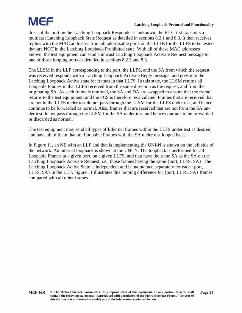
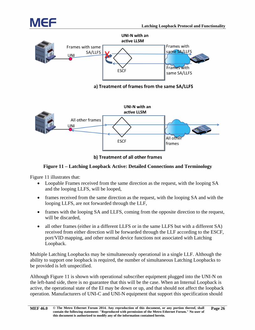
In Figure 11, an NE with an LLF and that is implementing the UNI-N is shown on the left side of the network. An internal loopback is shown at the UNI-N. The loopback is performed for all Loopable Frames at a given port, on a given LLFS, and that have the same SA as the SA on the Latching Loopback Activate Request, i.e., those frames having the same {port, LLFS, SA}. The Latching Loopback Active State is independent and is maintained separately for each {port, LLFS, SA} in the LLF. Figure 11 illustrates this looping difference for {port, LLFS, SA} frames compared with all other frames.
MEF 46.0 © The Metro Ethernet Forum 2014. Any reproduction of this document, or any portion thereof, shall contain the following statement: "Reproduced with permission of the Metro Ethernet Forum." No user of this document is authorized to modify any of the information contained herein.
Page 25
Latching Loopback Protocol and Functionality
Figure 11 – Latching Loopback Active: Detailed Connections and Terminology
Figure 11 illustrates that: • Loopable Frames received from the same direction as the request, with the looping SA
and the looping LLFS, will be looped,
• frames received from the same direction as the request, with the looping SA and with the looping LLFS, are not forwarded through the LLF,
• frames with the looping SA and LLFS, coming from the opposite direction to the request, will be discarded,
• all other frames (either in a different LLFS or in the same LLFS but with a different SA) received from either direction will be forwarded through the LLF according to the ESCF, port/VID mapping, and other normal device functions not associated with Latching Loopback.
Multiple Latching Loopbacks may be simultaneously operational in a single LLF. Although the ability to support one loopback is required, the number of simultaneous Latching Loopbacks to be provided is left unspecified.
Although Figure 11 is shown with operational subscriber equipment plugged into the UNI-N on the left-hand side, there is no guarantee that this will be the case. When an Internal Loopback is active, the operational state of the EI may be down or up, and that should not affect the loopback operation. Manufacturers of UNI-C and UNI-N equipment that support this specification should
MEF 46.0 © The Metro Ethernet Forum 2014. Any reproduction of this document, or any portion thereof, shall contain the following statement: "Reproduced with permission of the Metro Ethernet Forum." No user of this document is authorized to modify any of the information contained herein.
Page 26
Latching Loopback Protocol and Functionality
be aware that very often during the time that a service is activated, the connectivity and perfor-mance must be evaluated prior to the circuit being turned over to the subscriber, and thus prior to the subscriber’s equipment being plugged in with active links.
Note: When a Latching Loopback is active, because only packets matching the specified LLFS and SA are looped at the port, the port as a whole is otherwise operating normally. Accordingly, the port status is not changed, e.g., the operational status of the port is not changed as a result of a Latching Loopback being active, and neither does Latching Loopback being active cause a port to be placed in a locked state.
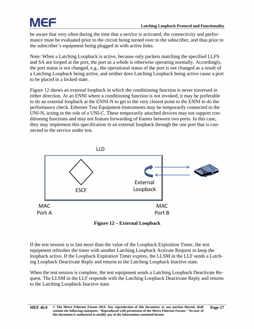
Figure 12 shows an external loopback in which the conditioning function is never traversed in either direction. At an ENNI where a conditioning function is not invoked, it may be preferable to do an external loopback at the ENNI-N to get to the very closest point to the ENNI to do the performance check. Ethernet Test Equipment-Instruments may be temporarily connected to the UNI-N, acting in the role of a UNI-C. These temporarily attached devices may not support con-ditioning functions and may not feature forwarding of frames between two ports. In this case, they may implement this specification in an external loopback through the one port that is con-nected to the service under test.
Figure 12 – External Loopback
If the test session is to last more than the value of the Loopback Expiration Timer, the test equipment refreshes the timer with another Latching Loopback Activate Request to keep the loopback active. If the Loopback Expiration Timer expires, the LLSM in the LLF sends a Latch-ing Loopback Deactivate Reply and returns to the Latching Loopback Inactive state.
When the test session is complete, the test equipment sends a Latching Loopback Deactivate Re-quest. The LLSM in the LLF responds with the Latching Loopback Deactivate Reply and returns to the Latching Loopback Inactive state.
MEF 46.0 © The Metro Ethernet Forum 2014. Any reproduction of this document, or any portion thereof, shall contain the following statement: "Reproduced with permission of the Metro Ethernet Forum." No user of this document is authorized to modify any of the information contained herein.
Page 27
Latching Loopback Protocol and Functionality
7.3 Latching Loopback Requirements
The LLF MUST be capable of associating an LLSM with a MEP. [R1]
At an ENNI, if a MIP is present, then the LLF MUST be capable of associating [R2]an LLSM with the MIP.
At a UNI, if a MIP is present, then the LLF MUST be capable of associating an [R3]LLSM with the MIP.
The external behavior of a LLF MUST be indistinguishable from that exhibited [R4]by instantiating an instance of the Latching Loopback State Machine on every possible {port, LLFS, SA} tuple, where each LLSM conforms to the specifica-tion in 7.1.
Note: This does not require that implementations actually instantiate a state machine for every possible {port, LLFS, SA}. In particular it is noted that no state needs to be maintained for state machines in Latching Loopback Prohibited state. In addition it is possible to instantiate a state machine for a given {port, LLFS, SA} only when a corresponding LL Activate message is re-ceived, since in Latching Loopback Inactive state, data traffic is handled normally. If a LLSM denoted by {port, LLFS, SA} is not in the Latching Loopback Active state and is not in the Latching Loopback Prohibited state, it can be considered to be in the Latching Loopback Inac-tive state.
The link state of a given port associated with an LLF MUST NOT have any [R5]impact on the behavior of the LLSMs associated with the port when responding to LLMs received by the LLF via a different port.
Latching Loopback Provisioning 7.3.1
The default state for all LLSMs within an LLD MUST be Latching Loopback [R6]Prohibited.
The LLD MUST be able to be provisioned on a per {port, LLFS} basis to set [R7]the state of all LLSMs for that {port, LLFS} to either the Latching Loopback Prohibited state or the Latching Loopback Inactive state.
[D1] The LLD SHOULD be able to be provisioned on a per {port, LLFS, SA} basis9 to set the state of all LLSMs for that {port, LLFS, SA} to either the Latching Loopback Prohibited state or the Latching Loopback Inactive state.
[D2] The LLD SHOULD be able to be provisioned to set the state for all LLSMs within the LLF to either the Latching Loopback Prohibited state or the Latching Loopback Inactive state.
9 In order to provision on a per {port, VLAN, SA} basis, the SA from which a Latching Loopback request would be received would have to be known a priori.
MEF 46.0 © The Metro Ethernet Forum 2014. Any reproduction of this document, or any portion thereof, shall contain the following statement: "Reproduced with permission of the Metro Ethernet Forum." No user of this document is authorized to modify any of the information contained herein.
Page 28
Latching Loopback Protocol and Functionality
[D3] The LLD SHOULD be able to be provisioned on a per port basis to set the state for all LLSMs on that port to either Latching Loopback Prohibited or Latching Loopback Inactive states.
Latching Loopback Prohibited State 7.3.2
An LLSM in Prohibited state MUST remain in Prohibited state across rebooting [R8]or restarting of the LLD or the port in the LLD implementing the LLSM.
Latching Loopback Inactive State 7.3.3
An LLSM in Inactive state MUST remain in Inactive state across rebooting or [R9]restarting of the LLD or the port in the LLD implementing the LLSM.
Latching Loopback Active State 7.3.4
When a Latching Loopback is active, SOAM frames received at the same MEG Level or a lower MEG Level as the MP associated with the LLF are handled as is normal for those SOAM frames. All other frames from the specified SA with the specified LLFS received from the specified port are looped (unless they are consumed by a MEP at a higher MEG Level or by a MIP).
The following requirements are specific to the Active state.
An LLSM in Active state MUST revert to Inactive state after rebooting or re-[R10]starting of the LLD or the port in the LLD implementing the LLSM.
An LLF MUST be able to support at least one {port, LLFS, SA} in the Latch-[R11]ing Loopback Active State.
If an Internal Loopback is activated, frame received at the EI from the CEN [R12]MUST be subjected to any egress conditioning function (e.g., ESCF or EPCF) and subsequently subjected to any ingress conditioning function.
If an External Loopback is activated, frames received at the EI from the Exter-[R13]nal Network MUST NOT be subjected to any egress conditioning function (e.g., ESCF or EPCF) or to any ingress conditioning function.
In the Latching Loopback Active state for a given {port, LLFS, SA}, the Latch-[R14]ing Loopback MUST swap each loopable unicast frame’s SA with the DA and recalculate the FCS as a part of looping back each looped frame.
In the Latching Loopback Active state for a given {port, LLFS, SA}, in the case [R15]where a {port, LLFS, SA} frame is received with a multicast or broadcast DA, the LLSM MUST: set the SA of the looped egressing frame to be the MAC address of the port where the Latching Loopback is located; set the DA of the looped egressing frame to be the SA of the received frame;
MEF 46.0 © The Metro Ethernet Forum 2014. Any reproduction of this document, or any portion thereof, shall contain the following statement: "Reproduced with permission of the Metro Ethernet Forum." No user of this document is authorized to modify any of the information contained herein.
Page 29
Latching Loopback Protocol and Functionality
and recalculate the FCS in the transmitted frame based on the revised frame arrangement.
When an LLR is sent by an LLF for an LLSM instance on a given {port, LLFS, [R16]SA}, the SA MUST be set to the MAC address of the MEP or MIP associated with the LLSM.
In Latching Loopback Active state, one of the following 5 cases must apply, corresponding with the 5 cases in which an LLFS is defined:
a) If the LLFS contains frames that are untagged at an EI, then all untagged frames passing through the LLF at that EI with the given SA are looped back. This would be the case, for example, at a UNI for a port-based service or at an ENNI. The associated MP could be, for example, a port-level Down MEP.
b) If the LLFS contains frames that contain a C-tag with a given CE-VLAN ID at a UNI, then all frames that contain that CE-VLAN ID as they pass through the LLF at that UNI, with the given SA, are looped back. This would be the case, for example, at a UNI for a VLAN-based service. The associated MP could be, for example, an Up MEP associated with the given CE-VLAN ID (which might or might not be its primary VID).
c) If the LLFS contains frames that contain an S-tag with a given S-VLAN ID, at an ENNI that does not have a VUNI for that S-VLAN ID, or at an ENNI that has a VUNI for that S-VLAN ID if the LL Activate Request was received over the ENNI, then all frames that contain that S-VLAN ID as they pass through the LLF at that ENNI, with the given SA, are looped back. This would be the case, for example, at an ENNI where the given S-VLAN ID is associated directly with an OVC End Point. The associated MP could be, for example, a down MEP associated with the given S-VLAN ID (which might or might not be its primary VID). In the case where the ENNI has a VUNI for the given S-VLAN ID, and the LL Activate request was received over the ENNI, the MP can only be a MIP or a down MEP, and the Latching Loopback can only be an External Loopback.
d) If the LLFS contains frames that contain an S-tag with a given S-VLAN ID, at an ENNI that has a VUNI associated with that S-VLAN ID, and that do not contain a C-tag, then all frames that contain that S-VLAN ID and do not contain a C-tag as they pass through the LLF at that ENNI, with the given SA, are looped back. This would be the case, for example, at an ENNI with a VUNI for the given S-VLAN ID, where the VUNI has an OVC End Point where untagged frames are mapped to a VLAN-based service10. The as-sociated MP could be, for example, a MIP on the VUNI associated with a CE-VLAN ID that uses untagged frames. The associated MP could be, for example, a MIP on the VUNI associated with untagged frames.
e) If the LLFS contains frames that contain an S-tag with a given S-VLAN ID, at an ENNI that has a VUNI associated with that S-VLAN ID, and a C-tag with a given CE-VLAN
10 One might use a VUNI for the untagged service in order to map EVCs based on DSCP, which can be done only at a UNI (or VUNI).
MEF 46.0 © The Metro Ethernet Forum 2014. Any reproduction of this document, or any portion thereof, shall contain the following statement: "Reproduced with permission of the Metro Ethernet Forum." No user of this document is authorized to modify any of the information contained herein.
Page 30
Latching Loopback Protocol and Functionality
ID, then all frames that contain that S-VLAN ID and CE-VLAN ID as they pass through the LLF at that ENNI, with the given SA, are looped back. This would be the case, for example, at an ENNI with a VUNI for the given S-VLAN ID, where the VUNI has an OVC End Point for a VLAN-based service. The associated MP could be, for example, a MIP on the VUNI associated with the given CE-VLAN ID (which might or might not be its primary VID).
Note 1: A device that is not CE-VLAN aware, receiving a frame that is CE-VLAN tagged, will treat it as a data frame; i.e., by default it will forward it. This means that one cannot loopback on an EVC basis to an RUNI, and one would therefore probably choose the corresponding VUNI instead.
Note 2: Because the S-VLAN ID is not changed on a loopback at an ENNI, it is not possible to do a loopback on an E-Tree service from a leaf UNI to an ENNI-N on the far side of an ENNI EI.
Note 3: An S-tagged frame arriving over an ENNI may belong to more than one LLFS, if the S-VLAN ID is associated with a VUNI. In this case the frame is looped back if the LLSM for any of the corresponding LLFSs is in the Latching Loopback Active State.
There are no special considerations for Latching Loopback being performed on a multipoint ser-vice because only the traffic from the originating SA sent to the port doing the loopback will be looped. See Figure 13.
MEF 46.0 © The Metro Ethernet Forum 2014. Any reproduction of this document, or any portion thereof, shall contain the following statement: "Reproduced with permission of the Metro Ethernet Forum." No user of this document is authorized to modify any of the information contained herein.
Page 31
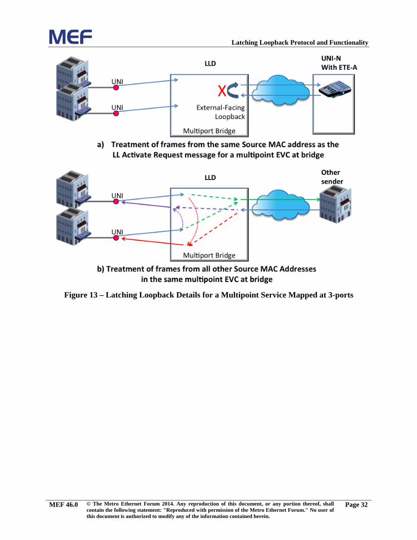
Latching Loopback Protocol and Functionality
Figure 13 – Latching Loopback Details for a Multipoint Service Mapped at 3-ports
MEF 46.0 © The Metro Ethernet Forum 2014. Any reproduction of this document, or any portion thereof, shall contain the following statement: "Reproduced with permission of the Metro Ethernet Forum." No user of this document is authorized to modify any of the information contained herein.
Page 32
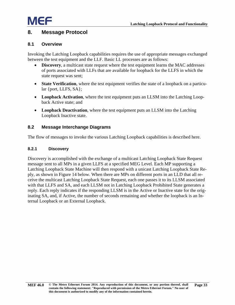
Latching Loopback Protocol and Functionality
8. Message Protocol
8.1 Overview
Invoking the Latching Loopback capabilities requires the use of appropriate messages exchanged between the test equipment and the LLF. Basic LL processes are as follows:
• Discovery, a multicast state request where the test equipment learns the MAC addresses of ports associated with LLFs that are available for loopback for the LLFS in which the state request was sent;
• State Verification, where the test equipment verifies the state of a loopback on a particu-lar {port, LLFS, SA};
• Loopback Activation, where the test equipment puts an LLSM into the Latching Loop-back Active state; and
• Loopback Deactivation, where the test equipment puts an LLSM into the Latching Loopback Inactive state.
8.2 Message Interchange Diagrams
The flow of messages to invoke the various Latching Loopback capabilities is described here.
Discovery 8.2.1
Discovery is accomplished with the exchange of a multicast Latching Loopback State Request message sent to all MPs in a given LLFS at a specified MEG Level. Each MP supporting a Latching Loopback State Machine will then respond with a unicast Latching Loopback State Re-ply, as shown in Figure 14 below. When there are MPs on different ports in an LLD that all re-ceive the multicast Latching Loopback State Request, each one passes it to its LLSM associated with that LLFS and SA, and each LLSM not in Latching Loopback Prohibited State generates a reply. Each reply indicates if the responding LLSM is in the Active or Inactive state for the orig-inating SA, and, if Active, the number of seconds remaining and whether the loopback is an In-ternal Loopback or an External Loopback.
MEF 46.0 © The Metro Ethernet Forum 2014. Any reproduction of this document, or any portion thereof, shall contain the following statement: "Reproduced with permission of the Metro Ethernet Forum." No user of this document is authorized to modify any of the information contained herein.
Page 33
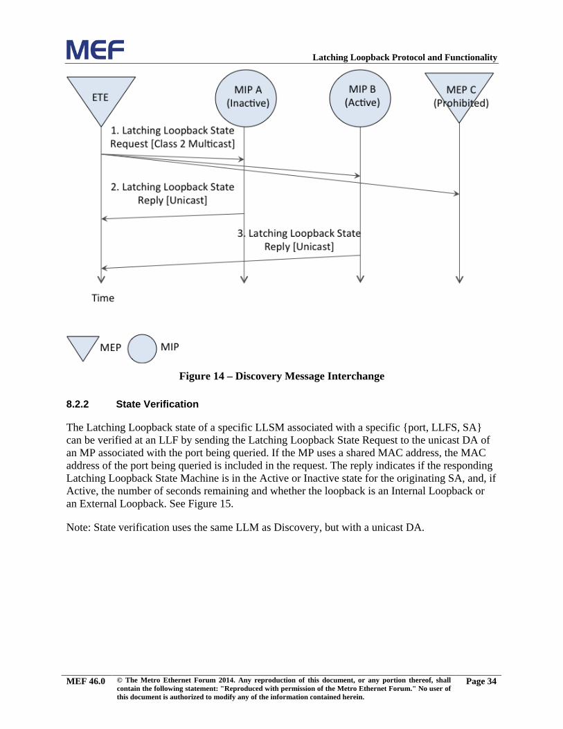
Latching Loopback Protocol and Functionality
Figure 14 – Discovery Message Interchange
State Verification 8.2.2
The Latching Loopback state of a specific LLSM associated with a specific {port, LLFS, SA} can be verified at an LLF by sending the Latching Loopback State Request to the unicast DA of an MP associated with the port being queried. If the MP uses a shared MAC address, the MAC address of the port being queried is included in the request. The reply indicates if the responding Latching Loopback State Machine is in the Active or Inactive state for the originating SA, and, if Active, the number of seconds remaining and whether the loopback is an Internal Loopback or an External Loopback. See Figure 15.
Note: State verification uses the same LLM as Discovery, but with a unicast DA.
MEF 46.0 © The Metro Ethernet Forum 2014. Any reproduction of this document, or any portion thereof, shall contain the following statement: "Reproduced with permission of the Metro Ethernet Forum." No user of this document is authorized to modify any of the information contained herein.
Page 34
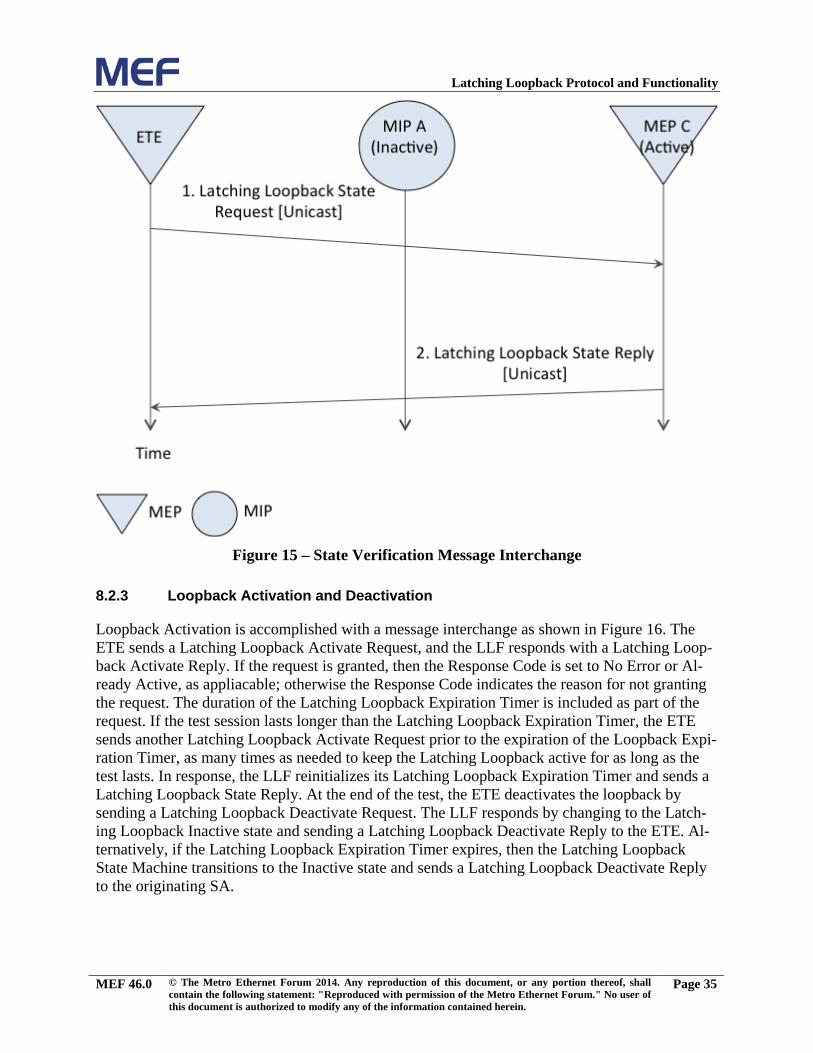
Latching Loopback Protocol and Functionality
Figure 15 – State Verification Message Interchange
Loopback Activation and Deactivation 8.2.3
Loopback Activation is accomplished with a message interchange as shown in Figure 16. The ETE sends a Latching Loopback Activate Request, and the LLF responds with a Latching Loop-back Activate Reply. If the request is granted, then the Response Code is set to No Error or Al-ready Active, as appliacable; otherwise the Response Code indicates the reason for not granting the request. The duration of the Latching Loopback Expiration Timer is included as part of the request. If the test session lasts longer than the Latching Loopback Expiration Timer, the ETE sends another Latching Loopback Activate Request prior to the expiration of the Loopback Expi-ration Timer, as many times as needed to keep the Latching Loopback active for as long as the test lasts. In response, the LLF reinitializes its Latching Loopback Expiration Timer and sends a Latching Loopback State Reply. At the end of the test, the ETE deactivates the loopback by sending a Latching Loopback Deactivate Request. The LLF responds by changing to the Latch-ing Loopback Inactive state and sending a Latching Loopback Deactivate Reply to the ETE. Al-ternatively, if the Latching Loopback Expiration Timer expires, then the Latching Loopback State Machine transitions to the Inactive state and sends a Latching Loopback Deactivate Reply to the originating SA.
MEF 46.0 © The Metro Ethernet Forum 2014. Any reproduction of this document, or any portion thereof, shall contain the following statement: "Reproduced with permission of the Metro Ethernet Forum." No user of this document is authorized to modify any of the information contained herein.
Page 35
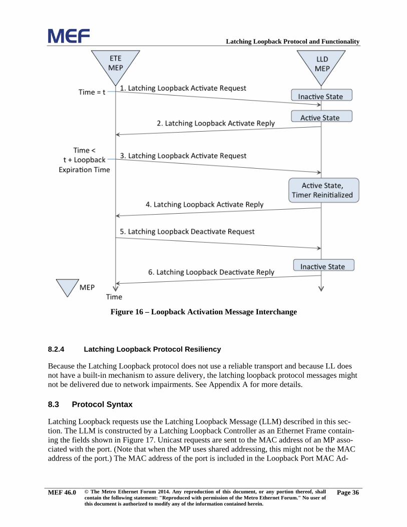
Latching Loopback Protocol and Functionality
Figure 16 – Loopback Activation Message Interchange
Latching Loopback Protocol Resiliency 8.2.4
Because the Latching Loopback protocol does not use a reliable transport and because LL does not have a built-in mechanism to assure delivery, the latching loopback protocol messages might not be delivered due to network impairments. See Appendix A for more details.
8.3 Protocol Syntax
Latching Loopback requests use the Latching Loopback Message (LLM) described in this sec-tion. The LLM is constructed by a Latching Loopback Controller as an Ethernet Frame contain-ing the fields shown in Figure 17. Unicast requests are sent to the MAC address of an MP asso-ciated with the port. (Note that when the MP uses shared addressing, this might not be the MAC address of the port.) The MAC address of the port is included in the Loopback Port MAC Ad-
MEF 46.0 © The Metro Ethernet Forum 2014. Any reproduction of this document, or any portion thereof, shall contain the following statement: "Reproduced with permission of the Metro Ethernet Forum." No user of this document is authorized to modify any of the information contained herein.
Page 36
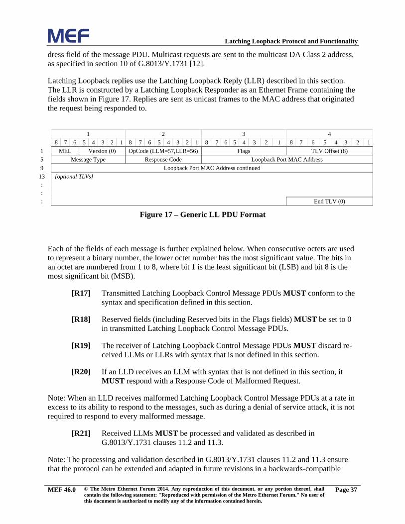
Latching Loopback Protocol and Functionality
dress field of the message PDU. Multicast requests are sent to the multicast DA Class 2 address, as specified in section 10 of G.8013/Y.1731 [12].
Latching Loopback replies use the Latching Loopback Reply (LLR) described in this section. The LLR is constructed by a Latching Loopback Responder as an Ethernet Frame containing the fields shown in Figure 17. Replies are sent as unicast frames to the MAC address that originated the request being responded to.
1 2 3 4 8 7 6 5 4 3 2 1 8 7 6 5 4 3 2 1 8 7 6 5 4 3 2 1 8 7 6 5 4 3 2 1 1 MEL Version (0) OpCode (LLM=57,LLR=56) Flags TLV Offset (8) 5 Message Type Response Code Loopback Port MAC Address 9 Loopback Port MAC Address continued
13 [optional TLVs] : : : End TLV (0)
Figure 17 – Generic LL PDU Format
Each of the fields of each message is further explained below. When consecutive octets are used to represent a binary number, the lower octet number has the most significant value. The bits in an octet are numbered from 1 to 8, where bit 1 is the least significant bit (LSB) and bit 8 is the most significant bit (MSB).
Transmitted Latching Loopback Control Message PDUs MUST conform to the [R17]syntax and specification defined in this section.
Reserved fields (including Reserved bits in the Flags fields) MUST be set to 0 [R18]in transmitted Latching Loopback Control Message PDUs.
The receiver of Latching Loopback Control Message PDUs MUST discard re-[R19]ceived LLMs or LLRs with syntax that is not defined in this section.
If an LLD receives an LLM with syntax that is not defined in this section, it [R20]MUST respond with a Response Code of Malformed Request.
Note: When an LLD receives malformed Latching Loopback Control Message PDUs at a rate in excess to its ability to respond to the messages, such as during a denial of service attack, it is not required to respond to every malformed message.
Received LLMs MUST be processed and validated as described in [R21]G.8013/Y.1731 clauses 11.2 and 11.3.
Note: The processing and validation described in G.8013/Y.1731 clauses 11.2 and 11.3 ensure that the protocol can be extended and adapted in future revisions in a backwards-compatible
MEF 46.0 © The Metro Ethernet Forum 2014. Any reproduction of this document, or any portion thereof, shall contain the following statement: "Reproduced with permission of the Metro Ethernet Forum." No user of this document is authorized to modify any of the information contained herein.
Page 37
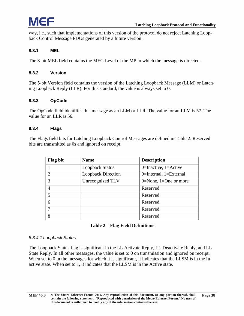
Latching Loopback Protocol and Functionality
way, i.e., such that implementations of this version of the protocol do not reject Latching Loop-back Control Message PDUs generated by a future version.
MEL 8.3.1
The 3-bit MEL field contains the MEG Level of the MP to which the message is directed.
Version 8.3.2
The 5-bit Version field contains the version of the Latching Loopback Message (LLM) or Latch-ing Loopback Reply (LLR). For this standard, the value is always set to 0.
OpCode 8.3.3
The OpCode field identifies this message as an LLM or LLR. The value for an LLM is 57. The value for an LLR is 56.
Flags 8.3.4
The Flags field bits for Latching Loopback Control Messages are defined in Table 2. Reserved bits are transmitted as 0s and ignored on receipt.
Flag bit Name Description 1 Loopback Status 0=Inactive, 1=Active 2 Loopback Direction 0=Internal, 1=External 3 Unrecognized TLV 0=None, 1=One or more 4 Reserved 5 Reserved 6 Reserved 7 Reserved 8 Reserved
Table 2 – Flag Field Definitions
8.3.4.1 Loopback Status
The Loopback Status flag is significant in the LL Activate Reply, LL Deactivate Reply, and LL State Reply. In all other messages, the value is set to 0 on transmission and ignored on receipt. When set to 0 in the messages for which it is significant, it indicates that the LLSM is in the In-active state. When set to 1, it indicates that the LLSM is in the Active state.
MEF 46.0 © The Metro Ethernet Forum 2014. Any reproduction of this document, or any portion thereof, shall contain the following statement: "Reproduced with permission of the Metro Ethernet Forum." No user of this document is authorized to modify any of the information contained herein.
Page 38
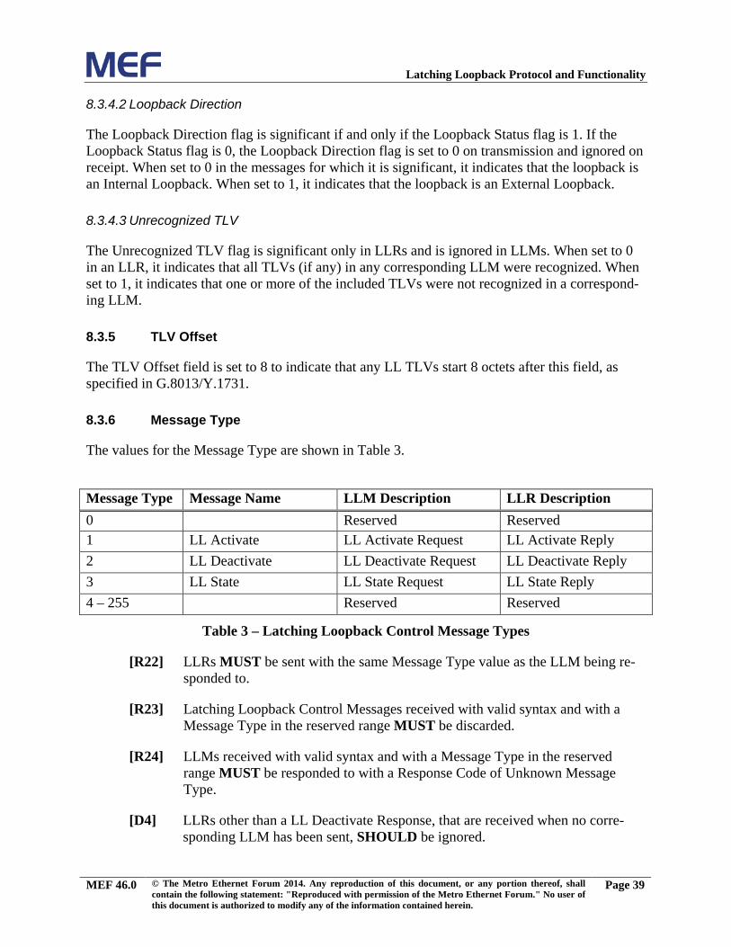
Latching Loopback Protocol and Functionality
8.3.4.2 Loopback Direction
The Loopback Direction flag is significant if and only if the Loopback Status flag is 1. If the Loopback Status flag is 0, the Loopback Direction flag is set to 0 on transmission and ignored on receipt. When set to 0 in the messages for which it is significant, it indicates that the loopback is an Internal Loopback. When set to 1, it indicates that the loopback is an External Loopback.
8.3.4.3 Unrecognized TLV
The Unrecognized TLV flag is significant only in LLRs and is ignored in LLMs. When set to 0 in an LLR, it indicates that all TLVs (if any) in any corresponding LLM were recognized. When set to 1, it indicates that one or more of the included TLVs were not recognized in a correspond-ing LLM.
TLV Offset 8.3.5
The TLV Offset field is set to 8 to indicate that any LL TLVs start 8 octets after this field, as specified in G.8013/Y.1731.
Message Type 8.3.6
The values for the Message Type are shown in Table 3.
Message Type Message Name LLM Description LLR Description 0 Reserved Reserved 1 LL Activate LL Activate Request LL Activate Reply 2 LL Deactivate LL Deactivate Request LL Deactivate Reply 3 LL State LL State Request LL State Reply 4 – 255 Reserved Reserved
Table 3 – Latching Loopback Control Message Types
LLRs MUST be sent with the same Message Type value as the LLM being re-[R22]sponded to.
Latching Loopback Control Messages received with valid syntax and with a [R23]Message Type in the reserved range MUST be discarded.
LLMs received with valid syntax and with a Message Type in the reserved [R24]range MUST be responded to with a Response Code of Unknown Message Type.
[D4] LLRs other than a LL Deactivate Response, that are received when no corre-sponding LLM has been sent, SHOULD be ignored.
MEF 46.0 © The Metro Ethernet Forum 2014. Any reproduction of this document, or any portion thereof, shall contain the following statement: "Reproduced with permission of the Metro Ethernet Forum." No user of this document is authorized to modify any of the information contained herein.
Page 39
Latching Loopback Protocol and Functionality
Note: Because the implementation of a Latching Loopback Controller is not provided by this document, what action, if any, that a Latching Loopback Controller takes in response to receiv-ing multiple unexpected LLRs is not provided.
All LLRs, and all LLMs except an LL State Request MUST have a unicast DA. [R25]
An LL State Request MUST have a unicast or class 2 multicast DA, as speci-[R26]fied in G.8013/Y.1731 clause 10.1.
Response Code 8.3.7
In LLRs, the Response Code field indicates the error or status of a reply. In LLMs, this field is set to 0 and ignored upon receipt. Possible values for Latching Loopback are shown in Table 4.
MEF 46.0 © The Metro Ethernet Forum 2014. Any reproduction of this document, or any portion thereof, shall contain the following statement: "Reproduced with permission of the Metro Ethernet Forum." No user of this document is authorized to modify any of the information contained herein.
Page 40
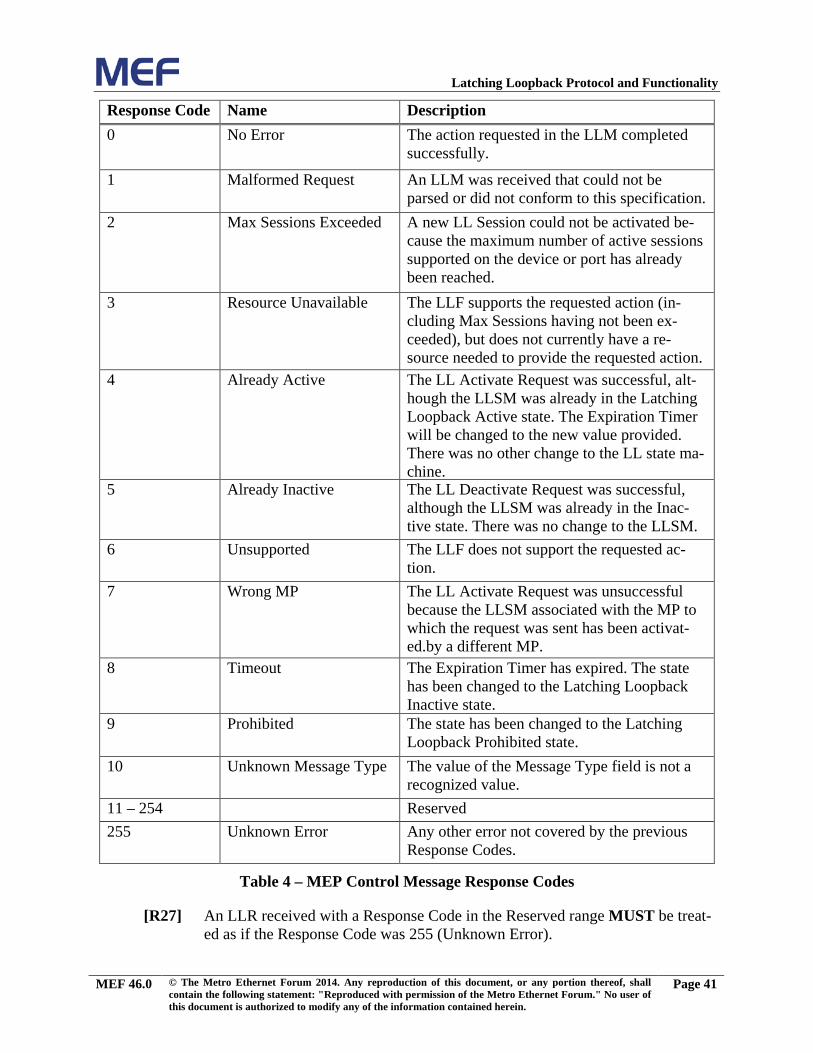
Latching Loopback Protocol and Functionality
Response Code Name Description 0 No Error The action requested in the LLM completed
successfully.
1 Malformed Request An LLM was received that could not be parsed or did not conform to this specification.
2 Max Sessions Exceeded A new LL Session could not be activated be-cause the maximum number of active sessions supported on the device or port has already been reached.
3 Resource Unavailable The LLF supports the requested action (in-cluding Max Sessions having not been ex-ceeded), but does not currently have a re-source needed to provide the requested action.
4 Already Active The LL Activate Request was successful, alt-hough the LLSM was already in the Latching Loopback Active state. The Expiration Timer will be changed to the new value provided. There was no other change to the LL state ma-chine.
5 Already Inactive The LL Deactivate Request was successful, although the LLSM was already in the Inac-tive state. There was no change to the LLSM.
6 Unsupported The LLF does not support the requested ac-tion.
7 Wrong MP The LL Activate Request was unsuccessful because the LLSM associated with the MP to which the request was sent has been activat-ed.by a different MP.
8 Timeout The Expiration Timer has expired. The state has been changed to the Latching Loopback Inactive state.
9 Prohibited The state has been changed to the Latching Loopback Prohibited state.
10 Unknown Message Type The value of the Message Type field is not a recognized value.
11 – 254 Reserved 255 Unknown Error Any other error not covered by the previous
Response Codes.
Table 4 – MEP Control Message Response Codes
An LLR received with a Response Code in the Reserved range MUST be treat-[R27]ed as if the Response Code was 255 (Unknown Error).
MEF 46.0 © The Metro Ethernet Forum 2014. Any reproduction of this document, or any portion thereof, shall contain the following statement: "Reproduced with permission of the Metro Ethernet Forum." No user of this document is authorized to modify any of the information contained herein.
Page 41
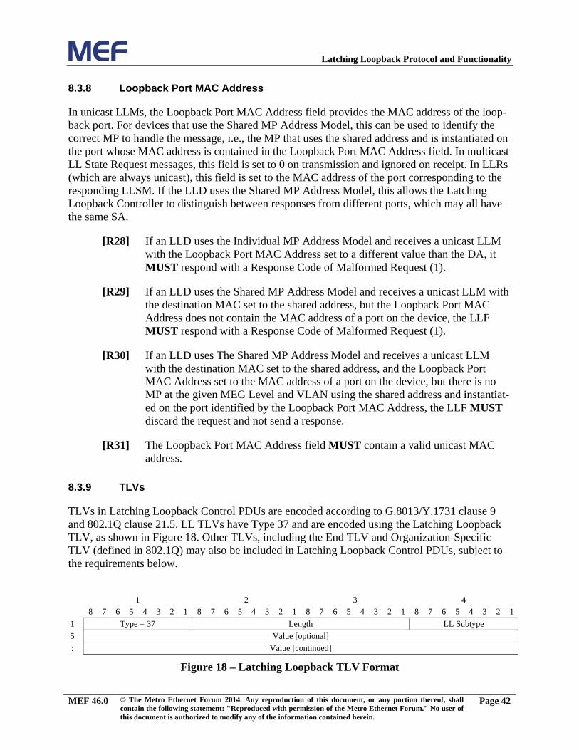
Latching Loopback Protocol and Functionality
Loopback Port MAC Address 8.3.8
In unicast LLMs, the Loopback Port MAC Address field provides the MAC address of the loop-back port. For devices that use the Shared MP Address Model, this can be used to identify the correct MP to handle the message, i.e., the MP that uses the shared address and is instantiated on the port whose MAC address is contained in the Loopback Port MAC Address field. In multicast LL State Request messages, this field is set to 0 on transmission and ignored on receipt. In LLRs (which are always unicast), this field is set to the MAC address of the port corresponding to the responding LLSM. If the LLD uses the Shared MP Address Model, this allows the Latching Loopback Controller to distinguish between responses from different ports, which may all have the same SA.
If an LLD uses the Individual MP Address Model and receives a unicast LLM [R28]with the Loopback Port MAC Address set to a different value than the DA, it MUST respond with a Response Code of Malformed Request (1).
If an LLD uses the Shared MP Address Model and receives a unicast LLM with [R29]the destination MAC set to the shared address, but the Loopback Port MAC Address does not contain the MAC address of a port on the device, the LLF MUST respond with a Response Code of Malformed Request (1).
If an LLD uses The Shared MP Address Model and receives a unicast LLM [R30]with the destination MAC set to the shared address, and the Loopback Port MAC Address set to the MAC address of a port on the device, but there is no MP at the given MEG Level and VLAN using the shared address and instantiat-ed on the port identified by the Loopback Port MAC Address, the LLF MUST discard the request and not send a response.
The Loopback Port MAC Address field MUST contain a valid unicast MAC [R31]address.
TLVs 8.3.9
TLVs in Latching Loopback Control PDUs are encoded according to G.8013/Y.1731 clause 9 and 802.1Q clause 21.5. LL TLVs have Type 37 and are encoded using the Latching Loopback TLV, as shown in Figure 18. Other TLVs, including the End TLV and Organization-Specific TLV (defined in 802.1Q) may also be included in Latching Loopback Control PDUs, subject to the requirements below.
1 2 3 4 8 7 6 5 4 3 2 1 8 7 6 5 4 3 2 1 8 7 6 5 4 3 2 1 8 7 6 5 4 3 2 1
1 Type = 37 Length LL Subtype 5 Value [optional] : Value [continued]
Figure 18 – Latching Loopback TLV Format
MEF 46.0 © The Metro Ethernet Forum 2014. Any reproduction of this document, or any portion thereof, shall contain the following statement: "Reproduced with permission of the Metro Ethernet Forum." No user of this document is authorized to modify any of the information contained herein.
Page 42
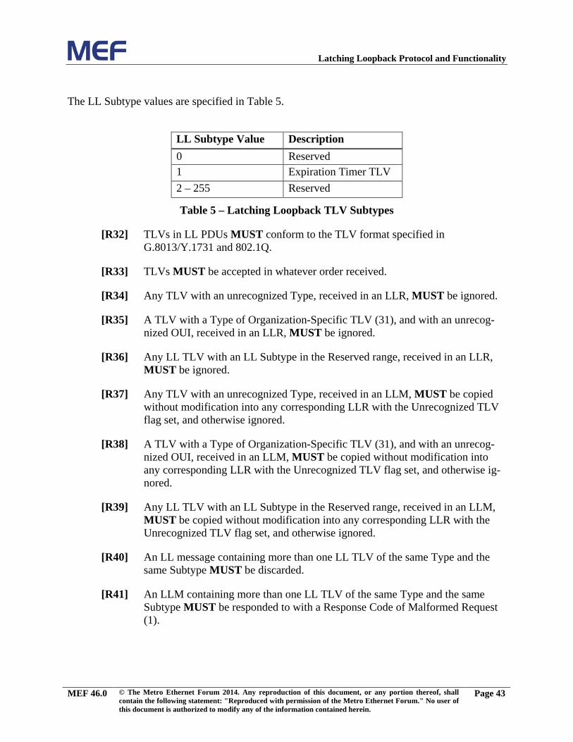
Latching Loopback Protocol and Functionality
The LL Subtype values are specified in Table 5.
LL Subtype Value Description 0 Reserved 1 Expiration Timer TLV 2 – 255 Reserved
Table 5 – Latching Loopback TLV Subtypes
TLVs in LL PDUs MUST conform to the TLV format specified in [R32]G.8013/Y.1731 and 802.1Q.
TLVs MUST be accepted in whatever order received. [R33]
Any TLV with an unrecognized Type, received in an LLR, MUST be ignored. [R34]
A TLV with a Type of Organization-Specific TLV (31), and with an unrecog-[R35]nized OUI, received in an LLR, MUST be ignored.
Any LL TLV with an LL Subtype in the Reserved range, received in an LLR, [R36]MUST be ignored.
Any TLV with an unrecognized Type, received in an LLM, MUST be copied [R37]without modification into any corresponding LLR with the Unrecognized TLV flag set, and otherwise ignored.
A TLV with a Type of Organization-Specific TLV (31), and with an unrecog-[R38]nized OUI, received in an LLM, MUST be copied without modification into any corresponding LLR with the Unrecognized TLV flag set, and otherwise ig-nored.
Any LL TLV with an LL Subtype in the Reserved range, received in an LLM, [R39]MUST be copied without modification into any corresponding LLR with the Unrecognized TLV flag set, and otherwise ignored.
An LL message containing more than one LL TLV of the same Type and the [R40]same Subtype MUST be discarded.
An LLM containing more than one LL TLV of the same Type and the same [R41]Subtype MUST be responded to with a Response Code of Malformed Request (1).
MEF 46.0 © The Metro Ethernet Forum 2014. Any reproduction of this document, or any portion thereof, shall contain the following statement: "Reproduced with permission of the Metro Ethernet Forum." No user of this document is authorized to modify any of the information contained herein.
Page 43
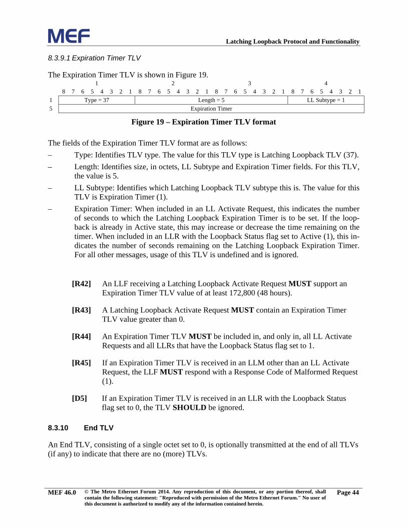
Latching Loopback Protocol and Functionality
8.3.9.1 Expiration Timer TLV
The Expiration Timer TLV is shown in Figure 19. 1 2 3 4 8 7 6 5 4 3 2 1 8 7 6 5 4 3 2 1 8 7 6 5 4 3 2 1 8 7 6 5 4 3 2 1
1 Type = 37 Length = 5 LL Subtype = 1 5 Expiration Timer
Figure 19 – Expiration Timer TLV format
The fields of the Expiration Timer TLV format are as follows: – Type: Identifies TLV type. The value for this TLV type is Latching Loopback TLV (37). – Length: Identifies size, in octets, LL Subtype and Expiration Timer fields. For this TLV,
the value is 5. – LL Subtype: Identifies which Latching Loopback TLV subtype this is. The value for this
TLV is Expiration Timer (1). – Expiration Timer: When included in an LL Activate Request, this indicates the number
of seconds to which the Latching Loopback Expiration Timer is to be set. If the loop-back is already in Active state, this may increase or decrease the time remaining on the timer. When included in an LLR with the Loopback Status flag set to Active (1), this in-dicates the number of seconds remaining on the Latching Loopback Expiration Timer. For all other messages, usage of this TLV is undefined and is ignored.
An LLF receiving a Latching Loopback Activate Request MUST support an [R42]Expiration Timer TLV value of at least 172,800 (48 hours).
A Latching Loopback Activate Request MUST contain an Expiration Timer [R43]TLV value greater than 0.
An Expiration Timer TLV MUST be included in, and only in, all LL Activate [R44]Requests and all LLRs that have the Loopback Status flag set to 1.
If an Expiration Timer TLV is received in an LLM other than an LL Activate [R45]Request, the LLF MUST respond with a Response Code of Malformed Request (1).
[D5] If an Expiration Timer TLV is received in an LLR with the Loopback Status flag set to 0, the TLV SHOULD be ignored.
End TLV 8.3.10
An End TLV, consisting of a single octet set to 0, is optionally transmitted at the end of all TLVs (if any) to indicate that there are no (more) TLVs.
MEF 46.0 © The Metro Ethernet Forum 2014. Any reproduction of this document, or any portion thereof, shall contain the following statement: "Reproduced with permission of the Metro Ethernet Forum." No user of this document is authorized to modify any of the information contained herein.
Page 44
Latching Loopback Protocol and Functionality
9. References
[1] MEF 10.3, Ethernet Services Attributes, Phase 3 October 2013
[2] MEF 26.1, External Network Network Interface, Phase 2, January 2012
[3] IETF RFC 2119, Key words for use in RFCs to Indicate Requirement Levels, March 1997
[4] MEF 30.1, Service OAM Fault Management Implementation Agreement, Phase 2, January 2013
[5] MEF 4, Metro Ethernet Architecture Framework – Part 1: Generic Framework, May 2004
[6] MEF 12.2, Carrier Ethernet Network Architecture Framework, Part 2: Ethernet Ser-vices Layer, October 2013
[7] IEEE 802.1Q, Virtual Bridged Local Area Networks, August 2011
[8] IEEE 802.1D, Media Access Control Bridges, June 2004
[9] IETF RFC 2544, Benchmarking Methodology for Network Interconnect Devices, March 1999
[10] ITU-T Y.1564, Ethernet service activation test methodology, March 2011
[11] IEEE 802, IEEE Standard for Local and Metropolitan Area Networks: Overview and Architecture, February 2002
[12] ITU-T G.8013/Y.1731, OAM functions and mechanism for Ethernet based networks, November 2013
[13] MEF 17, Service OAM Requirements & Framework – Phase 1, April 2007
MEF 46.0 © The Metro Ethernet Forum 2014. Any reproduction of this document, or any portion thereof, shall contain the following statement: "Reproduced with permission of the Metro Ethernet Forum." No user of this document is authorized to modify any of the information contained herein.
Page 45
Latching Loopback Protocol and Functionality
Appendix A Latching Loopback Protocol Resiliency (Informative)
Because the Latching Loopback protocol does not use a reliable transport and because LL does not have a built-in mechanism to assure delivery, the latching loopback protocol messages might not be delivered due to network impairments.
The use of an expiration timer in the LLSM means that at a high level, the protocol is resilient in the face of any control packet loss, in that the system is guaranteed to eventually return to the normal, loopback-inactive, state. However, it is useful to examine various cases in more detail, as this provides some guidance for a Latching Loopback Controller.
The first question is how the Latching Loopback Controller determines that a control packet has been lost. With the exception of the LL Deactivate Reply, all the control packet exchanges are initiated by the Latching Loopback Controller, and a reply is sent by the LLSM provided it is not in Loopback Prohibited state. If the Latching Loopback Controller does not receive an expected reply to a request, it may therefore infer that one of three possibilities has occurred:
• The LLSM is in Loopback prohibited state – note this includes all devices that do not support the LL protocol at all.
• The request was lost. In this case, there has been no change to the state on the LLSM.
• The reply was lost. In this case, the LLSM may or may not have changed state, depend-ing whether the request was successful.
Since it is unusual for networks to cause delay to packets of more than a second, a Latching Loopback Controller need only wait a short time after sending a request – for example 5 seconds – before assuming that one of the above possibilities has occurred.
The LL Deactivate Reply, as well as being used to respond to an LL Deactivate Request, is also sent autonomously by the LLSM on expiration of the loopback expiration timer. In addition, when a multicast LL state request is sent, the Latching Loopback Controller may not know from which LLSMs it should expect a reply, and hence will not be able to determine whether any mes-sages were lost. These two special cases are discussed further below.
Once a Latching Loopback Controller has determined that a control packet may have been lost, it can handle it in a number of ways, depending on the type of packet. The following subsections describe the recommended handling for each of the three pairs of packet types.
A.1 Loopback State Enquiry
The simplest case to deal with is a unicast LL State Request. If a Latching Loopback Controller sends an LL State Request but does not receive a reply, then whatever the cause, there is no change to the state of the LLSM and so the Latching Loopback Controller can simply retry the request after waiting a short time. If there is persistently no reply, the Latching Loopback Con-troller can wait for at least the expiration time, at which point it can be certain the LLSM is not in Loopback Active state.
MEF 46.0 © The Metro Ethernet Forum 2014. Any reproduction of this document, or any portion thereof, shall contain the following statement: "Reproduced with permission of the Metro Ethernet Forum." No user of this document is authorized to modify any of the information contained herein.
Page 46
Latching Loopback Protocol and Functionality
For a multicast LL State Request being used for discovery, the handling is more difficult. Since in this case, by definition, a Latching Loopback Controller does not know from which LLSMs it is expecting a reply, it cannot determine whether either the request or any replies have been lost. If it is important that LL state discovery works reliably, then it is recommended that some alter-native mechanism is used to ensure reliable connectivity with all parts of the network (for exam-ple CFM), and that the discovery process is repeated several times. Alternatively, as in the unicast case, the Latching Loopback Controller can simply wait for at least the expiration time so as to be sure there are no LLSMs in Loopback Active state.
A.2 Loopback Activate
If a Latching Loopback Controller sends an LL Activate Request but does not receive a reply, it again cannot determine which of the three possibilities was the cause. If the LLSM was in Loop-back Prohibited state, or if the request was lost, then the LLSM remains in whatever state it was previously in; if the reply was lost, the LLSM may have moved to Loopback Active state (if the request was successful) or have remained in its previous state (which could be Loopback Active or Loopback Inactive).
In some cases, a Latching Loopback Controller may know through out-of-band means whether a LLSM is in Loopback Prohibited state or not. If this is not the case, then since the Latching Loopback Controller cannot distinguish between the LLSM being in Loopback Prohibited state and a control packet being lost, it is recommended that the Latching Loopback Controller sends one or more unicast LL State Requests before sending the first LL Activate Request. If there is no reply to these LL State Requests, the Latching Loopback Controller may infer that either the LLSM is in Loopback Prohibited state or the network between them is down; in either case, it is recommended not to attempt to send an LL Activate Request. Conversely, if an LL State Reply is received, then the Latching Loopback Controller knows that the LLSM is in Loopback Active or Loopback Inactive state, and can send an LL Activate Request. Note there is still a window in which the LLSM could have been moved into Loopback Prohibited state between responding to the State Request and receiving the Activate Request; in this case it will appear to the Latching Loopback Controller that the activate message or reply has been lost, which can be handled as described below.
Assuming that a Latching Loopback Controller has determined whether the LLSM is in Loop-back Prohibited state – either by out-of-band means or by sending LL State Requests as de-scribed above – that leaves only two possibilities when no reply is received to an LL Activate Request: either the request was lost or the reply was lost.
The simplest way to distinguish between these cases is to send a unicast LL State Request, and examine the reply. If the LLSM is in Loopback Inactive state, it may be inferred that either the request was lost, or that it was unsuccessful; in either case, it may be retried. If the LLSM is in Loopback Active State, then the remaining expiration time can be examined to see whether it needs to be extended, in which case another LL Activate Request can be resent. If no reply is re-ceived to the LL State Request, then it itself can be retried as described in the previous section; failing that, the Latching Loopback Controller can – as in all cases – wait for the expiration time, at which point it will know the LLSM is no longer in Loopback Active state.
MEF 46.0 © The Metro Ethernet Forum 2014. Any reproduction of this document, or any portion thereof, shall contain the following statement: "Reproduced with permission of the Metro Ethernet Forum." No user of this document is authorized to modify any of the information contained herein.
Page 47
Latching Loopback Protocol and Functionality
A.3 Loopback Deactivate
Loopback Deactivate Requests are somewhat simpler to handle, as there are only limited cases where they are useful. In particular, it is recommended that they are sent only after a previous successful LL State Request or LL Activate Request. In either case, it is known that the LLSM is not in Loopback Prohibited (unless it has since been moved to that state), and so if no LL Deac-tivate Reply is received, it may be assumed that either the request or the reply was lost.
As in the case of an activate message, a Latching Loopback Controller cannot determine whether the LLSM has been deactivated (if the request was successful but the reply was lost), or re-mained in its previous state (if the request was lost or was not successful). However, in this case there is no need to probe for the state; the LL Deactivate Request can be retried directly.
As in the other cases, if there is persistently no reply to the LL Deactivate Requests, the Latching Loopback Controller may wait for the expiration time to be sure the loopback has been deac-tivated.
In addition to explicit LL Deactivate Requests from a Latching Loopback Controller, the LLSM also sends an LL Deactivate Reply whenever the loopback is deactivated due to the expiration timer expiring. If this message is lost, the Latching Loopback Controller will not receive confir-mation that the LLSM has moved to LL Inactive state. Nevertheless, the Latching Loopback Controller can assume that if it has waited sufficiently long, the expiration timer has indeed ex-pired and that the loopback has been deactivated. In order to account for the network latency and any clock skew, it is recommended that a Latching Loopback Controller wait some small amount of time longer than the expiration time –for example 5 seconds – before assuming that the loop-back has been deactivated.
If a Latching Loopback Controller does not receive the LL Deactivate Reply that it expects upon expiration of the timer, then it can confirm that the loopback has been deactivated by sending a unicast LL State Request. If no reply is received to the LL State Request, this can be handled as described earlier.
A.4 Loopback Expiration Time
In the discussion and recommendations above, there is an implicit assumption that a Latching Loopback Controller is aware of the loopback expiration time that it has set in any LL Activate Requests – or is at least aware of the maximum value this may be. This includes the case where a Latching Loopback Controller has been reset while there was a loopback in progress. To this end, it is recommended that a Latching Loopback Controller device uses a fixed value for the expiration time, or that if it is configurable, that the permitted values are restricted to a small range.
It is also recommended that the fixed value, or the maximum permitted value if it is configurable, is relatively short – for example 5 minutes. This is so as to limit the amount of time that a loop-back will continue to be active if there is a connectivity problem between a Latching Loopback Controller and the LLSM, such that no LL Deactivate Requests can be successfully sent. It is al-so recommended that a Latching Loopback Controller attempts to extend the expiration timer
MEF 46.0 © The Metro Ethernet Forum 2014. Any reproduction of this document, or any portion thereof, shall contain the following statement: "Reproduced with permission of the Metro Ethernet Forum." No user of this document is authorized to modify any of the information contained herein.
Page 48
Latching Loopback Protocol and Functionality
well in advance of it expiring – for example, 1 minute before – so as to leave time to implement the handling described above if no reply is received to the new LL Activate Request.
It is recommended that a Latching Loopback Controller not commence sending test traffic until it has confirmed that the LLSM is in Loopback Active State, either by receiving an LL Activate Reply with no error, or an LL State Reply indicating the LLSM is in Loopback Active state. Likewise, it also recommended to cease sending test traffic in advance of the expiration timer expiring – for example 10 seconds before – if it is unable to extend the time or confirm that the time has been extended.
Whenever the state of the LLSM is in doubt, because a control packet has been lost, it is recom-mended that a Latching Loopback Controller err on the side of caution and neither send test traf-fic nor allow normal data traffic to flow. If a Latching Loopback Controller is unable to confirm the LLSM state via an LL State Request, it is recommended that normal data traffic be resumed only once the Latching Loopback Controller has waited for at least the expiration time after the last LL Activate Request was sent, plus some allowance for network latency and clock skew – for example 5 seconds extra.
MEF 46.0 © The Metro Ethernet Forum 2014. Any reproduction of this document, or any portion thereof, shall contain the following statement: "Reproduced with permission of the Metro Ethernet Forum." No user of this document is authorized to modify any of the information contained herein.
Page 49