Embed Size (px)
Citation preview
LaserMark Software User Manual
Shenzhen RuiDa Technology CO., LTD
Tel: 86- 0755-26066687
Fax: 86-0755-26982287
Web: www.rd-acs.com
E-Mail: [email protected]
Add: 1B-1, Building 5, Tian'an Nanyou Industry Area,
Dengliang Road, Nanshan District, Shenzhen, P.R.C.

LaserMark Software User Manual
2 / 47
© 2016 Ruida Technology. All Rights Reserved.
CONTENTS
CONTENTS ..................................................................................................................................... 2
Copyright Declaration .................................................................................................................... 4
Chapter 1 Overview ........................................................................................................................ 5
1.1 Laser Marking System Introduction .................................................................................... 5
1.2 Software support file formats .............................................................................................. 5
1.3 Environmental requirements ............................................................................................... 5
1.3.1 Install controller driver ............................................................................................. 5
1.3.2 Exit ........................................................................................................................... 6
Chapter 2 Software Basic Operation ............................................................................................. 7
2.1 The operation main interface............................................................................................... 7
2.2 Language settings and manufactures information ............................................................... 8
2.3 Page Setting......................................................................................................................... 9
2.3.1 Work plat ................................................................................................................ 10
2.3.2 General Setting ....................................................................................................... 10
2.3.3 Interface Operation................................................................................................. 11
2.3.4 File Parameters ....................................................................................................... 12
2.3.5 Controller Information ........................................................................................... 13
2.4 File Open and Save ........................................................................................................... 13
2.4.1 Open File ................................................................................................................ 13
2.4.2 Save File ................................................................................................................. 14
2.5 File Import and Export ...................................................................................................... 14
2.5.1 File Import .............................................................................................................. 15
2.5.2 File export .............................................................................................................. 16
2.6 Basic graphics creation ..................................................................................................... 16
2.6.1 Point ....................................................................................................................... 16
2.6.2 Poly line ................................................................................................................. 16
2.6.3 Bezier curve ........................................................................................................... 17
2.6.4 Ellipse..................................................................................................................... 17
2.6.5 Rectangle ................................................................................................................ 17
2.6.6 Text ......................................................................................................................... 17
2.7 Object Selection ................................................................................................................ 17
2.8 Object Color ...................................................................................................................... 19
2.9 Object Transformation ...................................................................................................... 20
2.9.1 Primitives general property bar .............................................................................. 20
2.9.2 Transformation by mouse ....................................................................................... 21
2.9.3 Transformation by keyboard .................................................................................. 22
2.9.4 Graphic transformation tools .................................................................................. 23
2.10 Object Align .................................................................................................................... 24
2.11 Copy array ....................................................................................................................... 25

LaserMark Software User Manual
3 / 47
© 2016 Ruida Technology. All Rights Reserved.
2.12 Combination, Un-Combination, Group and Ungroup ..................................................... 25
2.13 View ................................................................................................................................ 26
2.14 Undo and Redo ................................................................................................................ 27
2.15 Cut, Copy, Paste .............................................................................................................. 27
2.16 Transform to Curve ......................................................................................................... 27
2.17 Filling .............................................................................................................................. 28
2.18 Image library ................................................................................................................... 29
Chapter 3 Process Operations ...................................................................................................... 32
3.1 The scanner correction ...................................................................................................... 32
3.1.1 Adjust Rectangle Size ............................................................................................ 33
3.1.2 Pincushion & Barrel distortion Correction ............................................................. 33
3.1.3 Trapezoid distortion correction .............................................................................. 35
3.1.4 Parallelogram distortion correction ........................................................................ 36
3.1.5 Live focus ............................................................................................................... 36
3.1.6 Correction dual-head scanner ................................................................................. 36
3.2 Laser Configuration .......................................................................................................... 37
3.2.1 CO2 laser ................................................................................................................ 37
3.2.2 YAG laser ............................................................................................................... 37
3.2.3 Fiber laser ............................................................................................................... 38
3.3 Scanner Setting ................................................................................................................. 39
3.4 Red indication parameter setting ....................................................................................... 41
3.5 Motor Parameters .............................................................................................................. 42
3.6 Limit Test .......................................................................................................................... 42
3.7 Marking layer parameters setting ...................................................................................... 43
3.8 Layer parameters library ................................................................................................... 44
3.9 Test .................................................................................................................................... 45
3.10 Marking ........................................................................................................................... 46

LaserMark Software User Manual
4 / 47
© 2016 Ruida Technology. All Rights Reserved.
Copyright Declaration
Shenzhen Ruida Technology Co., Ltd. (hereinafter referred to as “Ruida Technology”)
All rights reserved.
1. Ruida Technology holds the patent rights, copyrights and other intellectual property rights for
this product and its related software. Without authorization, none company or organization or
individual is allowed to copy, manufacture, process and use this product and its relative parts
directly or indirectly, otherwise shall be investigated for legal responsibility according to the
law.
2. Ruida Technology is entitled to increase or reduce and modify the products and functions of
this product stated herein as well as amend any documents attached to this product, without
prior notification.
3. The users should peruse this manual prior to using the product stated herein, Ruida
Technology shall not be responsible for the direct, indirect, special, incidental or
corresponding losses or damages arising out of improper use hereof or of this product as
below:
� Users using this manual or product improperly
� Users not follow the related safety operation rules
� The loss caused by the forces of nature
4. The machine in operation is dangerous, so the users are obliged to design and institute the
effective mechanism for error handling and safety protection. Ruida Technology shall not
undertake any duties or responsibilities for the incidental or corresponding losses arising
therefrom.

LaserMark Software User Manual
5 / 47
© 2016 Ruida Technology. All Rights Reserved.
Chapter 1 Overview
1.1 Laser Marking System Introduction
Laser marking system controls the laser making machine effectively through computer,
according to the user’s different requirements to complete the processing tasks.
The system includes control motherboard and supporting software. This manual describes
how to use the software to complete the task of laser processing.
1.2 Software support file formats
Vector format:dxf, ai, plt, dst, dsb…etc.
Bitmap format:bmp, jpg, gif, png, mng,…etc.
Customized file project: rdm
1.3 Environmental requirements
(1) Windows XP operating system or above, win 732 bit is recommended.
(2) CPU 1G above.
(3) Recommended to use above 1G memory.
1.3.1 Install controller driver
Open “device manager”, scan hardware change, right- click “PCI device” to install or update
driver.

LaserMark Software User Manual
6 / 47
© 2016 Ruida Technology. All Rights Reserved.
Found the folder "PCI driver" in software installation directory, and install the card driver
according to installation instructions. After installed successfully, check the device manager below
highlighted part device, if yes, installation is successful.
1.3.2 Exit
The system software installed, click “OK” to end it.
LaserMark Software User Manual
7 / 47
© 2016 Ruida Technology. All Rights Reserved.
Chapter 2 Software Basic Operation
2.1 The operation main interface
Double-click LaserMark icon on the desktop, you can start the software, if no control
card on user's computer, or PCI is not connected to the computer, the software will prompt
"connection controller failed, the system is in DEMO mode".
If control card inserted, please check whether the control card driver installed. Or shut down the
computer, then to confirm whether control card plugged reliable (or change the PCI slots).
In DEMO mode, only basic graphics operations, no data export function and some special
functions.
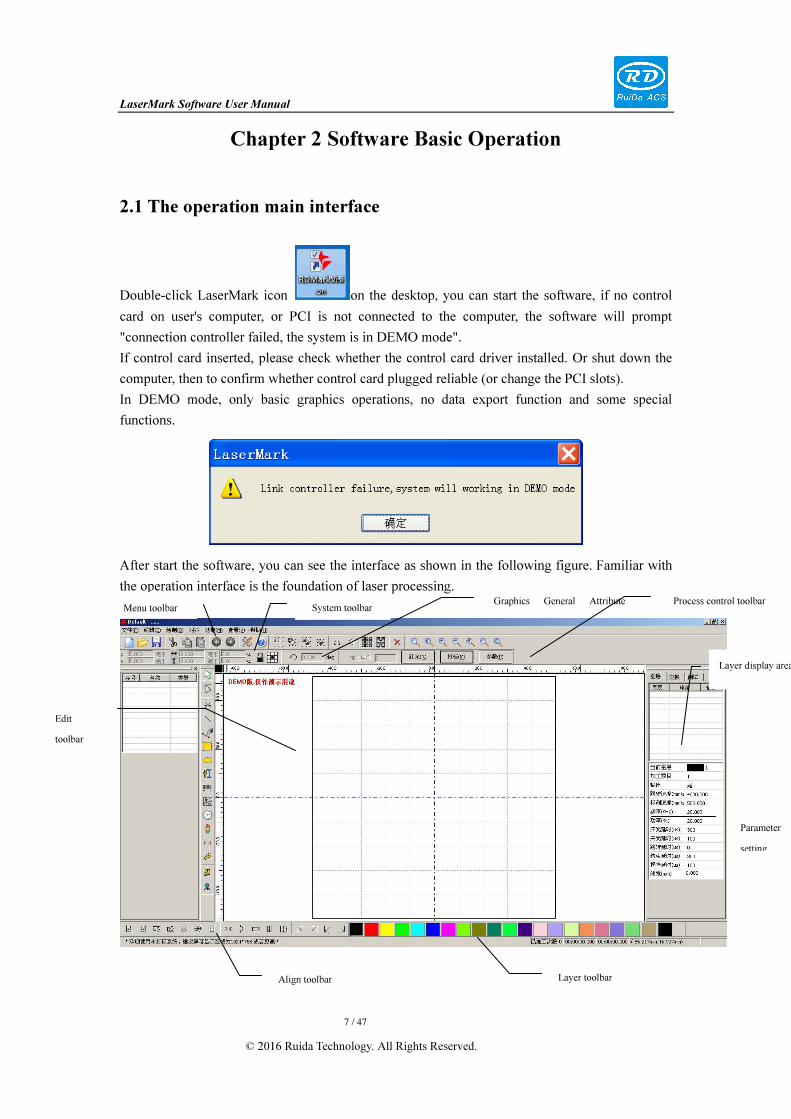
After start the software, you can see the interface as shown in the following figure. Familiar with
the operation interface is the foundation of laser processing.
Menu toolbar System toolbar
Align toolbar Layer toolbar
Edit
toolbar
Graphics General Attribute
Parameter
setting
Layer display area
Process control toolbar

LaserMark Software User Manual
8 / 47
© 2016 Ruida Technology. All Rights Reserved.
Menu Toolbar:The main functions of this software are available through the Menu Bar. Execute
the menu command is the most basic mode of operation. Menu Bar including: Document, Edit,
Draw, Setting, Processing, View and Help.
Graphics General Attribute Toolbar: Graphics property bar is the basic attributes of graphics
operations, including graphic location, size, scale, processing No..
Graphics Dedicated Attribute Toolbar: To modify the graphics attribute of different types,
dedicated attribute bar will display the update if the current selected graphics changed.
System Toolbar: On the System Bar, placed some most commonly command buttons which is
chosen from the menu.
Align Toolbar: Align the multiple selected objects, and optimize the typesetting.
Control Panel: Control panel is mainly to achieve some common operations and settings.
Layer Toolbar: Modify the color of the selected object.
Edit Toolbar: The Edit Bar default on the left of the work area. In the Edit Bar placed
frequently-used tools to make the operation more flexible and convenient.
2.2 Language settings and manufactures information
In addition to set the software language types in the process installation, you can also easily switch
different languages.
Click Menu Bar【Help】->【语言/Language】to unfold menu,select the required language types.
To obtain manufacturers information, we can provide you with better service.
Click Menu Bar【Help】->【About LASERMARK】

LaserMark Software User Manual
9 / 47
© 2016 Ruida Technology. All Rights Reserved.
How to set manufacturers information, please refer to 《LASERMARK software installation
instructions》.
The current software version number will be displayed at the bottom of the dialog box. For
different versions of software may be have some differences on the functions and interfaces, you
can easily contact and communicate with manufacturers through software version number.
2.3 Page Setting
Click Menu Bar【Config】->【System setting】, the following dialog box will be appeared:

LaserMark Software User Manual
10 / 47
© 2016 Ruida Technology. All Rights Reserved.
2.3.1 Work plat
It specifies the size, shape and other information of the software drawing workspace.
[Work space size]: The width and height of work area. The unit is mm.
[Round space]: The workspace shape can switch between rectangular and circular. Generally, it is
determined by the shape of actual marking work surface, default as rectangular.
[Show cross line]: It can show or hide the zero baseline of the work area.
[Show grid]: supporting designer design the layout of workspace graphics intuitively, or to
quickly measuring the graph size. If user does not need the grid that you can hide the grid display.
The grid size can change moderately according to the marking accuracy requirements.
[Zero Position]: Determine the location of Zero coordinate in the workspace.
2.3.2 General Setting
The general settings function is mainly match software to user's machine.
[Input mask] [Output mask]: The system provides 8 IO inputs and 8 IO outputs for optional.
Actually, the machine does not to use all IO. Set the mask can shield the unused IO. Avoid user
uses the unused IO.
[Foot switch]: Select this function, user click on “OK”, it will not be immediately output.
Software waits for the user to pressure on foot pedal to trigger the marking. Especially for
repetition marking, marking can be set to "Continuous process" and trigger the marking by foot
switch, so that avoid repeating the operation and reducing the operator’s labor intensity.
The trigger signal of foot switch can be set as well. When high level trigger, the foot switch can

LaserMark Software User Manual
11 / 47
© 2016 Ruida Technology. All Rights Reserved.
be set as high level trigger; if low level trigger, it can be set as low level trigger.
2.3.3 Interface Operation
Interface operation sets the shortcut key to set parameters.
User can control the selected graphics’ transformation by the arrow keys and auxiliary key
directly.
[Move Step]: Set the graphics’ translation moving distance when each click on the arrow keys.
[Rotate Step]: Set the graphics’ rotation angle. (press down Ctrl key and click on the arrow keys
to rotate the graphic)
[Key Ratio]: Set proportion of the graphics’ moving and rotation.
Press down the Shift key and press the arrow keys to move quickly as the distance= [Move Step]
*[Key Ratio] .
Press down the Shift + Ctrl key and press the arrow keys to rotate rapidly as the distance= [Rotate
Step] *[Key Ratio].

LaserMark Software User Manual
12 / 47
© 2016 Ruida Technology. All Rights Reserved.
2.3.4 File Parameters
File parameters are set to the accuracy and the data processing-parameters of the import file.
[PLT Precision]: Set PLT file’s import unit.
If the import PLT graph size same as the original image, the PLT unit must be specified as the
original actual unit.
DXF Unit: The default unit is mm, if the import DXF data is inconsistent with the original
graphics, which may be caused by different unit. Optional units: mm, cm, inch, customization. If
customization, user sets any unit data in DXF file should correspond to the software unit mm.
Import DXF Text info:User cannot check this item when only needed the graphic information of
DXF, not the text information.
Smooth curves: When import vector file, automatically smoothing the original curves. For the
original graphic is smooth or need to repeatedly adjust the beset smoothing effect, you can
uncheck this button to reduce time of import processing.
Auto close curves:Auto - check and closed curve according to close error.
Combine lines:Auto-connect curves according to combine error.

LaserMark Software User Manual
13 / 47
© 2016 Ruida Technology. All Rights Reserved.
2.3.5 Controller Information
Software supports to get firmware version information from main control card chip, the user can
know the controller support functions according to the firmware version information, as reference
whether need to upgrade. The user does not need to know the specific meaning of each version.
Controller supports online upgrade firmware as well, click 【 upgrade 】 button, choose the right
version of the upgrade file, you can upgrade the firmware.
Upgrade is completed, shut down and restart the computer, controller will load the new firmware
program automatically.
2.4 File Open and Save
The software uses rld-format file to save graphic information, layer parameters of various layers
and processing sequence of the graphic elements. Therefore, save the import data graphics as rdm
file, it is easy for output processing.
2.4.1 Open File
Click menu【File】->【Open】,or click , the following dialog box will be appeared:

LaserMark Software User Manual
14 / 47
© 2016 Ruida Technology. All Rights Reserved.
(2) Select file to open (e.g. Default.rld), then click【Open】.
2.4.2 Save File
(1)Click menu【File】->【Save】,or click icon ,the following dialog box will be appeared:
(2)Enter the file name in the edit box,then click【Save】.
2.5 File Import and Export
For this software is rld-format, so to make or edit other materials need to import. And export
the finished graphic files to fit for other software. Support import file format: dxf, ai, plt, dst,
dsb...etc. Support export file format: plt and ai.
Select file
Input file name
LaserMark Software User Manual
15 / 47
© 2016 Ruida Technology. All Rights Reserved.
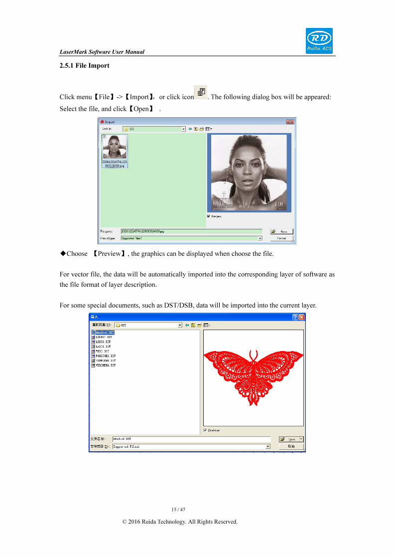
2.5.1 File Import
Click menu【File】->【Import】,or click icon . The following dialog box will be appeared:
Select the file, and click【Open】 .
◆Choose 【Preview】, the graphics can be displayed when choose the file.
For vector file, the data will be automatically imported into the corresponding layer of software as
the file format of layer description.
For some special documents, such as DST/DSB, data will be imported into the current layer.

LaserMark Software User Manual
16 / 47
© 2016 Ruida Technology. All Rights Reserved.
2.5.2 File export
Click menu【File】->【Export】or click icon . The Export dialog box appears.
Input file name, and click button【Save】.
Support PLT and AI format file.
2.6 Basic graphics creation
The graphics can be created in Work-Place mode and in Module-page mode.
2.6.1 Point
Click menu【Draw】->【Point】, or click Edit Bar . Click the mouse on the screen, you can
draw a line. Choose the point to set the related parameters of graphics. The point parameters
include position and emit light time.
2.6.2 Poly line
Click menu【Draw】->【Poly line】,or click Edit Bar . Drag the mouse on the working area
to determine the start point of poly line.
Drag the mouse on the working area to determine the intermediate point of poly line, increase the
point in turn to form a poly line.
Press “Control” + dragging the mouse to draw a horizontal line and vertical line.
LaserMark Software User Manual
17 / 47
© 2016 Ruida Technology. All Rights Reserved.
Right click mouse to end the drawing.
2.6.3 Bezier curve
Click menu【Draw】->【curve】,or click Edit Bar .
Please refer to the “Poly line”, the difference is that you can left click and drag the mouse to
adjust the control point after inserting the intermediate point.
2.6.4 Ellipse
Click menu【Draw】->【Ellipse】, or click Edit Bar .
2.6.5 Rectangle
Click menu【Draw】->【Ellipse】, or click Edit Bar .
Move the mouse and click any position in the workspace to determine the rectangle starting point.
Press down the mouse and drag to adjust the rectangle size. Meanwhile, press “CTRL” key to
draw a square.
Loose the left mouse button to end rectangular drawing.
2.6.6 Text
Click menu【Draw】->【Text】,or click Edit Bar . Move the mouse and click any position
in the workspace to create text as default character “TEXT”.
2.7 Object Selection
In the process of drawing and edit graphics, the first thing is to select the object.
When the object is being selected, in the center of this object will have a shaped mark“ × ”,and
surrounded by eight control points.

LaserMark Software User Manual
18 / 47
© 2016 Ruida Technology. All Rights Reserved.
Click menu【Draw】->【Select】,or click Edit Bar ,switch to “Select” status. Under this status,
you can select object. The followings are five kinds of select method:
◆ Click menu【Edit】->【Select All】(Shortcuts Ctrl+A), select all objects.
◆ Click mouse to select single object.
Select object using select box◆
Press the mouse and drag, as long as the box come into contact with the object will be selected.
Increased select object/minus select object◆
Increase select:Firstly, select the first object and then keep pressing “Shift” key and click or box
select to the other increased objects.
Minus select:Click “Shift” key or box selects the selected object.
Select object ◆ from graphics primitive list
LaserMark Software User Manual
19 / 47
© 2016 Ruida Technology. All Rights Reserved.
Primitives list also support various selection mode:
Group Selection: Press SHIFT key, select the first primitive and last primitive, the software will
automatically select all the primitives from the first to the last.
Add Selection: Press CTRL key, will add one if select one primitive.
Remove Selection: Press CTRL key, select the primitives again from the selected primitives, so
this primitive will be removed from the range.
Notice: The auxiliary primitives (delay, IO input, the output IO, the shaft moving) are not
graphics, so there is no outline, which cannot be selected in the workspace, for this type of
primitives can be selected in the primitives list.
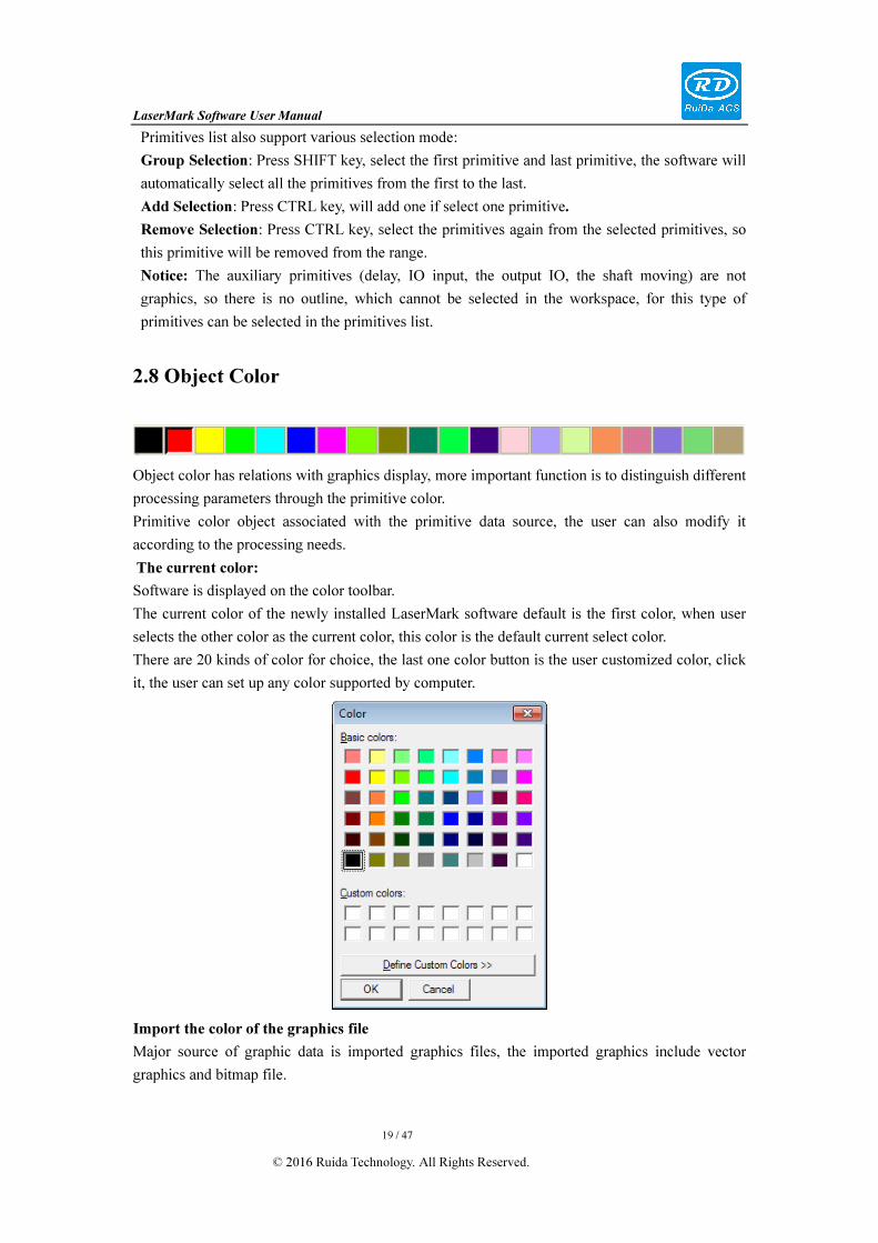
2.8 Object Color
Object color has relations with graphics display, more important function is to distinguish different
processing parameters through the primitive color.
Primitive color object associated with the primitive data source, the user can also modify it
according to the processing needs.
The current color:
Software is displayed on the color toolbar.
The current color of the newly installed LaserMark software default is the first color, when user
selects the other color as the current color, this color is the default current select color.
There are 20 kinds of color for choice, the last one color button is the user customized color, click
it, the user can set up any color supported by computer.
Import the color of the graphics file
Major source of graphic data is imported graphics files, the imported graphics include vector
graphics and bitmap file.

LaserMark Software User Manual
20 / 47
© 2016 Ruida Technology. All Rights Reserved.
The bitmap file is only pixel color, but no concept of the color of the entire graphics, and
introduced the concept of bitmap graphic primitives in LaserMark in order to distinguish
processing parameters of different bitmap. When the bitmap file imported, the software default to
the color of the bitmap is the current color.
For vector graphics file, we currently support the formats: PLT, AI, DXF, DST, DSB.
DST, DSB file is not including color information, its color, our software defaults to the current
color.
AI, DXF file contains color information; the color of import graphic is the graphics color.
PLT contains the color value, only layer number, there may be inconsistent between the imported
color and the software designed the PLT.
Notice:
1. Whatever AI or DXF, if graphics color is white, the software will automatically convert white
graphics into black due to the background color of LaserMark software is white.
2. For some AI format file, its color system is suitable for printing CMYK color, but the RGB
color we used is suitable for displaying, there may be a certain color difference in the process
from CMYK to RGB, t, but usually does not affect the normal use.
3. Save PLT graphics in CorelDraw, default only eight layers, if saved more than eight PLT layers,
there will be the drawing colors do not match the PLT color.
Painting color:
All graphics drawn by LaserMark software directly will take the current color as graphics color.
Change color:
Choose the graphics of the color to be changed, and then click on the color you would like to set
in toolbar, and then you can change color graphics.
After changing color, the processing parameters of corresponding graphics are changed
accordingly.
2.9 Object Transformation
The object transformation mainly includes: object location, dimensions, aspect ratio, tilt,
mirror, rotation and other basic transformation.
2.9.1 Primitives general property bar
Translation: users can input coordinates of target position to X, Y directly, the translation done.

LaserMark Software User Manual
21 / 47
© 2016 Ruida Technology. All Rights Reserved.
X, Y value has relations with , click the button to set the position benchmark coordinates.
Position coordinates benchmark can choose as shown in figure.
The currently selected is the middle point, means that the current X, Y value is central point
coordinates of the current selected graphics.
Just like this, if select top left point, the X and Y values represents the top left point coordinates of
current selected graphics.
Rotation: input rotation angle, then click button, the selected graphics can be rotated
around its middle point.
Size: and respectively corresponding to the width and height of selected graphic. Input
values to change the graphic dimension.
If you need lock aspect ratio, press the button to .
Zoom : respectively represents the scaling of width and height, input values to scaling
graphics. If need zoom the graphics in an equal proportion, press the button to .
2.9.2 Transformation by mouse
Selected graphics, eight black points and a "X" will be appeared around graphics.
Translation: move mouse to "X", and press, you can drag graphics to the target
location.
Uniform scaling: move four black points with mouse, press the mouse and drag,
you can scaling graphics in equal proportion.
Single direction scaling: mouse moved to the black spots at the centre of the

LaserMark Software User Manual
22 / 47
© 2016 Ruida Technology. All Rights Reserved.
four edges, press mouse and drag, scaling graphics can be done in the corresponding direction.
Double-click the "X" point, eight points around the graphics will become eight icons with arrows.
Rotation: mouse move the four peak rotation arrows, press the mouse and drag, then rotating the
graphics.
Skew: mouse move to arrow icons at the centre of the four edges, press the mouse and drag, you
can tilt the graphics in the corresponding direction.
2.9.3 Transformation by keyboard
After selected graphics, press the keyboard direction key to implement graphic translation and
rotation conveniently.
The parameters setting, please refer to 2.3.3 interface operation parameters.
[Move Step]: Set the graphics’ translation moving distance when each click on the arrow keys.
[Rotate Step]: Set the graphics’ rotation angle. (press down Ctrl key and click on the arrow keys
to rotate the graphic)
[Key Ratio]: Set proportion of the graphics’ moving and rotation.
Press down the Shift key and press the arrow keys to move quickly as the distance= [Move Step]
*[Key Ratio] .
Press down the Shift + Ctrl key and press the arrow keys to rotate rapidly as the distance= [Rotate
Step] *[Key Ratio].

LaserMark Software User Manual
23 / 47
© 2016 Ruida Technology. All Rights Reserved.
2.9.4 Graphic transformation tools
Translation Rotate Mirror Size
Skew
1. Translation
Uncheck the "relative position", H and V: respectively represent the horizontal coordinates and
vertical coordinates of the selected location.
As shown in the figure to choose the middle point, H and V represent the coordinates of the
center of the selected object.
Modify H and V, click "Apply", can translation the graphics.
Modify H and V, click "Apply to copy", can copy new graphics in specified location.
Check "relative position", H and V: respectively represent the horizontal offset and vertical
offset of the selected relative position of the target position.

LaserMark Software User Manual
24 / 47
© 2016 Ruida Technology. All Rights Reserved.
2. Rotation
Input rotation angle, choose location point, then can rotate around it. If need keep the rotation
center always the same point in the process of continuous rotation, choose the "lock rotate center
".
3. Mirror
Mirror transform function is divided into three parts: the scaling, horizontal/vertical mirror,
mirror axis position.
Scaling is scaling by default, if you need not to scale, check the "no ratio”.
Mirror has three types of combination: horizontal mirror, vertical mirror, horizontal/vertical
mirror at the same time.
Mirror axis position can choose 9 positions:
If only choose horizontal/vertical mirror, so the optional mirror axis only three of
horizontal/vertical. If both, there are 9 mirror axes for choice.
4. Size
H and V respectively correspond to the width and height of selected object.
Nine points is used to specify which point based on the graphic to zoom graphics.
5. Skew
Uncheck the "use point", the default anchor point is the center of the graphics.
Check the "use point", the anchor point is the user selected location point.
H angle corresponds to the horizontal skew angle.
V angle corresponds to the vertical skew Angle.
2.10 Object Align
Select objects,then click tools on the Align Bar:
.
: Left alignment, Right alignment, Top alignment, Bottom alignment.
: Vertical center alignment, Horizontal center alignment, Center alignment.
: The horizontal equidistance and vertical equidistance of the border of the selected
object.
: Equal width, equal height, equal size.
Align Benchmark Object: If you press “Shift” key and select object one by one, then take the last
one as the benchmark. For frame box, take the last curves number as benchmark.

LaserMark Software User Manual
25 / 47
© 2016 Ruida Technology. All Rights Reserved.
: align with the working area of the upper left corner, the upper right corner,
the lower left corner, and the bottom right corner.
2.11 Copy array
Choose edit toolbar , select array object replication. Then click the object action toolbar ,
he following dialog will be appeared:
X [number]: array number in horizontal.
Y [number]: array number in vertical.
X [space]: when the icon is , represents the space of edge to edge in horizontal; When the
icon is , represents horizontal center spacing of the graphics.
Y [spacing]: when the icon is , represents the space of edge to edge in vertical; When the
icon is , graphics center spacing in vertical.
Array direction, you can choose four directions--lower right, lower left, upper left, upper
right.
: two-way processing array, : one-way processing array
2.12 Combination, Un-Combination, Group and Ungroup
Combination and group functions are merge multiple objects into one
object; it is convenient to graphics operations. The differences between combination and group:
composition is effective for vector graphics, but the group is effective to all the primitive types our
software supported.
If combination of multiple objects, and the object contains non-vector graphics, the software will
automatically remove these non-vector graphics.
Ungroup is corresponding to group, so do the functions.

LaserMark Software User Manual
26 / 47
© 2016 Ruida Technology. All Rights Reserved.
2.13 View
To view the software graphics by checking the toolbar ,
the mouse and keyboard shortcuts together.
1. View the page
In general, page represents the scanner processing area.
It can be directly switch to the entire page display in drawing process at any time.
Click button , or press F4 to view page.
2. View all graphics
Click button or press the F2 key to display all of the primitives in the software.
3. View selected graphics
Click button or press the F3 key to display the selected graphics.
4. Drag view
After clicking button , the mouse will become , hold the left mouse button and drag it.
5. Frame view
Frame view is mainly used for observe the graphics details, click button , move the mouse
to the wanted position, press mouse left button and drag to draw a rectangle, then release the left
mouse button, the range of rectangle box will be displayed to maximization.
6. Zoom view
If you want to take the center of working area as the center of the zoom, click button
or .
If zoom in center of the mouse cursor position, you can move the mouse cusor to the wanted
position, and scroll the mouse.

LaserMark Software User Manual
27 / 47
© 2016 Ruida Technology. All Rights Reserved.
2.14 Undo and Redo
If graphics operations process must be back to the last step, click button , or press
shortcut key CTRL + Z.
If graphics operation need to restore the just undo operation, click button , or press
CTRL + Y.
Undo and restore operations are limited to graphics operations, modify the parameters and
other settings are irrevocable, only can be reset, and under Module-page mode is unavailable.
2.15 Cut, Copy, Paste
Software supports for graphics (vector graphics or bitmap) arbitrary cutting, copy and paste at any
position on the display area.
Cut: select the graphics, click button or press CTRL + X.
Copy: select the graphics, point button or press CTRL + C.
Paste: cut or copy the graphics, move the mouse to any position in display area, click button
or press CTRL + V.
2.16 Transform to Curve
For some vector graphics with special properties, such as text, bar code, users may need to modify
the content, type, and other proprietary properties. But it is also need to
implement some functions proprietary property can not realize, such as the
word disassembled into letters, and arrange the letters as you wanted, or
deformation. So it is better to users for transforming the graphics into curves.
The operation of transform to curve is very simple, only need to select
graphics, and right-click on it, and select "transform to curve" on the
right-click menu.

LaserMark Software User Manual
28 / 47
© 2016 Ruida Technology. All Rights Reserved.
2.17 Filling
First, select an object and click the toolbar button or
right-click the “Hatch” option in the pop-up menu. It will pop
up the dialog box to set parameters.
Enable Outline: Whether to output the filled contour.
The filling can be divided into three layers to fill at different
angles, which making the effective processing filling more
evenly. Stratified filling parameters are identical.
Enable: Whether to fill the current layer or not.
Layers: Fill line belongs to layer. Layers involve the
processing parameters of the filling line. If no special requirements, the three layers generally use
the same layer.
Around the edge once: Whether to output the contour after a layer filling finished.
Angle: Filling angle. The practical effective angle is 0- 180 degrees.
Line Spacing: Intervals of the filling line, the user can determine spacing according to the actual
effect requirements.
Start Offset
End Offset: In the process, the high speed may cause the movement and the laser does not match.
Thus, it will make difference between the actual emitting laser position and graphics. Although
this part of error can be compensated by adjusting the parameters, but it will inevitably reduce the
processing speed and need some experience and time to adjust it well.
In less demanding circumstances, a simple way is to adjust the start offset and end offset,
compensate the filling line mandatory which beyond the contour line or not yet reached the
contour.
Start offset and end offset values can be positive or negative, that is, the filling line can stretch
outward to inward contraction.
Two-way filling, One-way filling, the scanner path is different.
Delete filling: delete the graphics filling function.

LaserMark Software User Manual
29 / 47
© 2016 Ruida Technology. All Rights Reserved.
2.18 Image library
Software users create their own gallery file, and reuse the frequently primitives.
1. Create library
The newly installed software is generally without library files, users can create a new library.
2. Add graphics
Add graphics to create library. Graphics can be import into the software or drawn directly in
software. Library supports the added vector / bitmap graphics.
Open the library; select the graphics you want to add. Click the library dialog box “add
graphics” button (the button is grayed when no graphics selected).
Click “Add Image” button and named for the graphics, so the graphics added to the library.
Recommend: Do not add too much graphics in a single library. Too many graphics in a single
library may cause too long time for displaying.

LaserMark Software User Manual
30 / 47
© 2016 Ruida Technology. All Rights Reserved.
3. Delete graphic
Select the graphic you want to delete. The button “Del Image” is enabled.
Click on “Del Image” and click on “OK”. Graphics will be deleted from the library.
4. Delete library
Select the library you want to delete in Library Name List .Then click on “Del lib” and press
down “OK”. Library will be deleted.
5. Export library graphics to LaserMark software
Choose the graphics you want to export to LaserMark in the library and drag to the interface of
RDMarkVision.
The exported size of graphics is determined by “Graphic Options”.

LaserMark Software User Manual
31 / 47
© 2016 Ruida Technology. All Rights Reserved.
Original Size: Export the graphics as original size.
Lock Scale: The proportion of exported graphics is the original proportion; width is set as user
request. If you do not check the “Lock Scale”, the width and height of the exported graphics be set
by user.
6. Library reuse
Create a library, library files will be saved in folder named “Img-Lib” under the RDMark software
installation directory. A file represents a library.
User wants to use the library, just need to copy the library files to the “Img Lib” folder under the
installation directory of RDMark.
LaserMark Software User Manual
32 / 47
© 2016 Ruida Technology. All Rights Reserved.
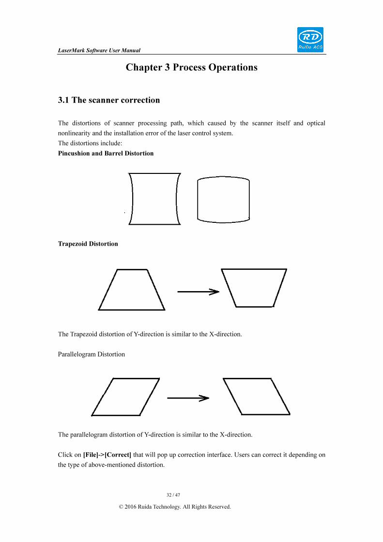
Chapter 3 Process Operations
3.1 The scanner correction
The distortions of scanner processing path, which caused by the scanner itself and optical
nonlinearity and the installation error of the laser control system.
The distortions include:
Pincushion and Barrel Distortion
Trapezoid Distortion
The Trapezoid distortion of Y-direction is similar to the X-direction.
Parallelogram Distortion
The parallelogram distortion of Y-direction is similar to the X-direction.
Click on [File]->[Correct] that will pop up correction interface. Users can correct it depending on
the type of above-mentioned distortion.

LaserMark Software User Manual
33 / 47
© 2016 Ruida Technology. All Rights Reserved.
About the laser settings and processing parameters will be described in the following chapters.
This section focuses on the tuning correction steps.
3.1.1 Adjust Rectangle Size
Set the appropriate laser parameters and processing parameters firstly, and then click “Output
rectangle” button. Observe the output rectangle size.
The software can support 10000bit to 40000bit rectangle for testing. The actual output maximum
size of the rectangle has relations with the assembly structure of vibrating mirror, such as the lens
size, lens distance, the distance between lens and the focusing lens, and the thickness of focusing
lens. Adjust the rectangle size, making the output testing rectangle to be greater as much as
possible. Only the testing rectangle covers the processing area as much as possible which can
correct the whole breadth.
3.1.2 Pincushion & Barrel distortion Correction
The adjustment range of pincushion and barrel distortion parameters is 0.5-1.
Step 1: Output a test rectangle A, keep the test workpiece not move.
Step 2: Adjust a value. Then output another test rectangle B.
Step 3: Observe the change in which direction and remember it, if the actul output is not obvious,
adjust the value smaller.
Step 4: The different parameters corresponding to different results. Based on the above results.You
can obtain the scanner installation wiring information and the corresponding relationship
information of software.
LaserMark Software User Manual
34 / 47
© 2016 Ruida Technology. All Rights Reserved.
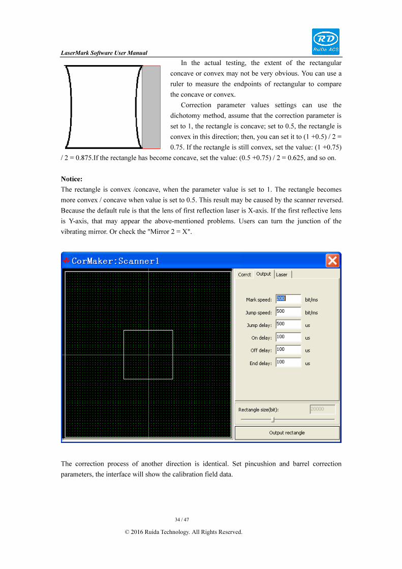
In the actual testing, the extent of the rectangular
concave or convex may not be very obvious. You can use a
ruler to measure the endpoints of rectangular to compare
the concave or convex.
Correction parameter values settings can use the
dichotomy method, assume that the correction parameter is
set to 1, the rectangle is concave; set to 0.5, the rectangle is
convex in this direction; then, you can set it to (1 +0.5) / 2 =
0.75. If the rectangle is still convex, set the value: (1 +0.75)
/ 2 = 0.875.If the rectangle has become concave, set the value: (0.5 +0.75) / 2 = 0.625, and so on.
Notice:
The rectangle is convex /concave, when the parameter value is set to 1. The rectangle becomes
more convex / concave when value is set to 0.5. This result may be caused by the scanner reversed.
Because the default rule is that the lens of first reflection laser is X-axis. If the first reflective lens
is Y-axis, that may appear the above-mentioned problems. Users can turn the junction of the
vibrating mirror. Or check the "Mirror 2 = X".
The correction process of another direction is identical. Set pincushion and barrel correction
parameters, the interface will show the calibration field data.

LaserMark Software User Manual
35 / 47
© 2016 Ruida Technology. All Rights Reserved.
3.1.3 Trapezoid distortion correction
In the process of Pincushion and barrel distortion correction, confirm that the correction
parameters of lens 1 and lens 2 corresponding to which directions respectively.
Measuring the opposite side’s length of rectangular at any directions, if the lengths are equal,
which shows there is no trapezoidal distortion in this direction. Not all of scanner system exit
trapezoid distortion.
The trapezoid distortion range is 0.5-1.5.
If a trapezoidal distortion in a direction, users can input a value in the corresponding lens .
And then output the test rectangle. To confirm whether the change trend of value is consistent with
the results we want in this direction.
Example: In pincushion and barrel distortion correction, if you know the corresponding lens 1
in up and down direction, and the test rectangle is distortion, measuring the top length is wider
than bottom.
User can set trapezoidal distortion parameters of lens 1 as 0.5, and then output the test
rectangle. If the output test rectangle’s bottom is wider than top, you can know the trend of the
values are right. The value must be between 0.5 and 1 to make the length of rectangle sides equal.
If the trapezoidal distortion parameter is set to 0.5, the output rectangle’s top is wider than
bottom. Then set the rectangle’s value must between 1 and 1.5 to make the edges equal.
Another direction of the correction process is identical. Set the trapezoid correction parameters,
the interface will display the calibration field data.
Notice: The Trapezoid correction requires the opposite sides are equal. Does not require the
four sides are equal.

LaserMark Software User Manual
36 / 47
© 2016 Ruida Technology. All Rights Reserved.
3.1.4 Parallelogram distortion correction
After the above two steps correction, the four sides of the rectangle are straight and the width of
up and down are equal, so do left and right edges. But it may be a parallelogram distortion; the
diagonals of the rectangle are not equal.
First of all, you can measure the rectangle diagonal. If the two diagonals are equal or a very small
error, there is no parallelogram distortion.
Parallelogram distortion may be distortion
horizontally, vertically or both directions.
Therefore, correct parallelogram distortion, to
distinguish the kind of parallelogram firstly, the
parallelogram is extremely small in actual.
Correction software will output the rectangle center
cross line when output the rectangle. Through
measuring the relative position of cross line, you can
judge the shape of a parallelogram distortion.
Measure the horizontal line of upper and lower
rectangle. Check the position of vertical line of the
center cross line in horizontal line. You can know whether parallelogram distortion in horizontal
direction. If the rectangle’s upper horizontal line takes the vertical line of the center cross line as
dividing line, the left part is longer than the right, so its shape as Picture 1 showed. You can set
to any value, then output the test rectangle again. Observe the left parts shorted than the
right part. The correction method is similar to Trapezoid correction aforementioned. If insert 0.9,
the left part is shorten comparing to the right part. Its value must be between 0.9 and 1. Otherwise
its value must be greater than 1.
Use the above way to test the parallelogram distortion horizontally and vertically.
3.1.5 Live focus
Check “Live focus”, enable live focus function.
Fill “z-axis moving distance” and “scanning radius” as actual.
3.1.6 Correction dual-head scanner
Ruida marking controller and marking software can support dual head of vibrating mirror.
The correction method is the same as single head, switch “mirror 1” and “mirror 2”.
After correction, LaserMark software will load the correction sheets for the two scanner
automatically.

LaserMark Software User Manual
37 / 47
© 2016 Ruida Technology. All Rights Reserved.
3.2 Laser Configuration
Click on the "Parameter" button at the right, you can open the output parameter settings.
Select the matching laser type according to the actual laser. Reference the marking card of RuiDa
user's manual on the wiring of the different laser.
Different laser for each laser are required to set the minimum frequency and maximum frequency
of subsequent processing parameter settings to be limited. Generally, the frequency uses default
value.
3.2.1 CO2 laser
For CO2 laser, “enable standby pulse” if needed.
Standby pulse, controller can always send pulse signal
to laser power supply with certain frequency and pulse
width at any time.
In the process of standby pulse working, laser device
will not emit laser, but in a critical state all the time,
that is, will emit laser when pulse width added.
To improve the response of laser in this way.
【 Min Frequency 】 Set the minimum laser
frequency .The unit is KHz.
【Max Frequency】Set the maximum laser frequency. The unit is KHz.
【Enable standby】 You can enable the standby.
【Standby frequency】The CO2 RF laser tube need standby frequency. Usually, it is 5KHz.
【Standby width】Set the width of pulse. Usually, it is 1us.
【Freq analog output】Enable the frequency analog output.
【Power analog output】Enable the power analog output.
【Freq map】You can define the special frequency. For example, you can define 80K as 100K.
【Power map】You can define the special Power. For example, you can define 100% as 80%.
3.2.2 YAG laser
Generally, YAG laser have the first pulse inhibit function to eliminate the impact of the first

LaserMark Software User Manual
38 / 47
© 2016 Ruida Technology. All Rights Reserved.
pulse.
The first pulse suppression width is set depending on the actual laser.
In addition, the YAG has two working mode. The difference between Mode 1 and Mode 2 is that
whether needs to wait for the end of the first pulse to open Q-switched.
Mode 2, you can check the “Open Q-switch
after FPK”.
The system default level is high. If the laser
power received signal is low. Check the "Invert
pulse”.
【Min Frequency】 Set the minimum laser
frequency , the unit is KHz.
【Max Frequency】Set the maximum laser
frequency. The unit is KHz.
【PPS width】Set the first pulse’s width. The
unit is us.
【Max current】Set the maximum electricity output to laser device.
3.2.3 Fiber laser
【Min Frequency】Set the minimum laser frequency. The unit is KHz.
【Max Frequency】Set the maximum laser frequency.
The unit is KHz.
【MO delay】The fiber laser required MO trigger level
delay a moment. Usually, the delay is 5ms.
【Type】The laser type.
【Leak Handle】In the early time, the fiber laser set
MO as high level, the laser switch is low level, laser
output low light level of 20mmw. If the material is
sensitive to laser, you should make the machine not
output laser when the machine does not work.
You should check this option to solve the problem.
LaserMark Software User Manual
39 / 47
© 2016 Ruida Technology. All Rights Reserved.
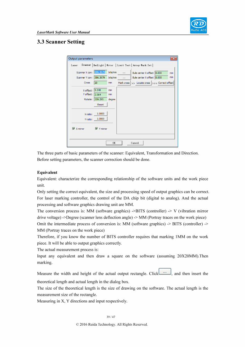
3.3 Scanner Setting
The three parts of basic parameters of the scanner: Equivalent, Transformation and Direction.
Before setting parameters, the scanner correction should be done.
Equivalent
Equivalent: characterize the corresponding relationship of the software units and the work piece
unit.
Only setting the correct equivalent, the size and processing speed of output graphics can be correct.
For laser marking controller, the control of the DA chip bit (digital to analog). And the actual
processing and software graphics drawing unit are MM.
The conversion process is: MM (software graphics) ->BITS (controller) -> V (vibration mirror
drive voltage) ->Degree (scanner lens deflection angle) -> MM (Portray traces on the work piece)
Omit the intermediate process of conversion is: MM (software graphics) -> BITS (controller) ->
MM (Portray traces on the work piece)
Therefore, if you know the number of BITS controller requires that marking 1MM on the work
piece. It will be able to output graphics correctly.
The actual measurement process is:
Input any equivalent and then draw a square on the software (assuming 20X20MM).Then
marking.
Measure the width and height of the actual output rectangle. Click , and then insert the
theoretical length and actual length in the dialog box.
The size of the theoretical length is the size of drawing on the software. The actual length is the
measurement size of the rectangle.
Measuring in X, Y directions and input respectively.

LaserMark Software User Manual
40 / 47
© 2016 Ruida Technology. All Rights Reserved.
Repeat the above steps. You can get the correct scanner equivalent.
Transformation:
LaserMark supports three kinds of scanner transformation: translation, rotation, scaling.
For some work piece place position is not accurate, or translation, rotation and scaling relations
between the scanner coordinate system and the work piece coordinate system. We can set
change-parameters directly without needing to transform the graphics on the drawing area; the
processing output can be realized.
Direction:
When drawing and displaying graphics with LaserMark software, the default coordinate system is
, that is, right side is X direction, upward is Y direction.
But the work piece coordinate system in actual processing may be , , . The
actually situation relates to machine installation.
When in actual test, output any graphics easy to judge the direction. Such as output the text
"TEXT". And then select the directions of the scanner based on test results.
【cross length】Set the length of cross.
【mark cross】Set the coordinate system offset, rotation and mirror correctly according to the
current drawing coordinate system of the cross,.
Note:If you click the “mark cross” function button, , represents Y
positive direction, represents X positive direction.

LaserMark Software User Manual
41 / 47
© 2016 Ruida Technology. All Rights Reserved.
3.4 Red indication parameter setting
Before marking, the red-light is used to determine the marking data range.
In theory, the red-light and the laser are in the same optical axis. So it can be thought that the
location of the red-light marked is the laser marking location. But actually, it may have a certain
spacing between the red-light optical axis and the laser optical axis. If you need to accurate
position, you can set the "Red offset X" and "Red offset Y" to compensate and correct red-light.
The red-light indication can indicate the bounding rectangle of the processed graphics, and also as
the graphics outline indicates. If you need indicates the outline, check “output outline”. You can
set the scanner transformation to mark the workpiece with inaccurate placed position. It is difficult
to determine its value that set the scanner transformation parameters manually for correction
applications. In fact, this process can be completed in the process of red-light indication.
In red-light indication process:
1. User can press the arrow keys to set the transformation offset of scanner processing location.
2. Press CTRL key and the up and down key at the same time to set the rotation errors of the
vibrating mirror machining position.
3. Press SHIFT key and execute step1 & step2 at the same time, it can realize fast translation or
rotation.
[Red Speed]: movement speed of red light, the unit: mm/s
[Output outline]: when the red light indicated, output graphics outline.
[Red offset X] [Red offset Y]: because of red light and actual laser is not in the same optical axis,
thus can set up red offset to let the red light and laser in the same axis.
[Step length]: press arrow key one time to move.
[Pulse Angle]: press CTRL and arrow key one time at the same time to rotate angle.
[Scale adjustment]: press SHIFT, translation or rotation speed ratio.
After adjusting, LaserMark will update scanner transformation parameter settings automatically in
scanner parameters settings interface.

LaserMark Software User Manual
42 / 47
© 2016 Ruida Technology. All Rights Reserved.
3.5 Motor Parameters
【equivalent】:Set the Motor equivalent.
You can click the button to
calculate.
【control mode】:Set the working mode
of the motor. There are two modes:
pulse + direct and +/- pulse.
【orientation】 :Set the orientation of
motor.
【positive limit】:Set the trigger level of
the positive limit.
【negative limit】:Set the trigger level of
the negative limit.
【Limit enable】: Enable the limit.
【start speed】Set the start speed.
【Max. speed】Set the maximum speed.
【Stop Acc】Set the stop acceleration.
3.6 Limit Test
【Positive limit】【Negative limit】: the state of limit. If the limit is
triggered, the light turns to red color. The limit is not triggered, the
light is green color.
【Alarm】It is the alarm status. If alarmed, the light will be red
color; if no, the light will be green.
【Reset】Reset the state of limit and alarm when limit triggered.
LaserMark Software User Manual
43 / 47
© 2016 Ruida Technology. All Rights Reserved.
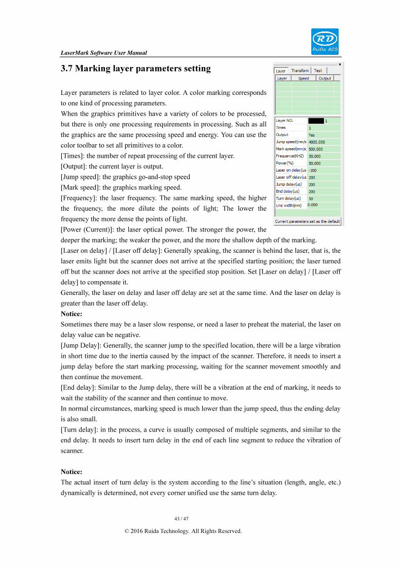
3.7 Marking layer parameters setting
Layer parameters is related to layer color. A color marking corresponds
to one kind of processing parameters.
When the graphics primitives have a variety of colors to be processed,
but there is only one processing requirements in processing. Such as all
the graphics are the same processing speed and energy. You can use the
color toolbar to set all primitives to a color.
[Times]: the number of repeat processing of the current layer.
[Output]: the current layer is output.
[Jump speed]: the graphics go-and-stop speed
[Mark speed]: the graphics marking speed.
[Frequency]: the laser frequency. The same marking speed, the higher
the frequency, the more dilute the points of light; The lower the
frequency the more dense the points of light.
[Power (Current)]: the laser optical power. The stronger the power, the
deeper the marking; the weaker the power, and the more the shallow depth of the marking.
[Laser on delay] / [Laser off delay]: Generally speaking, the scanner is behind the laser, that is, the
laser emits light but the scanner does not arrive at the specified starting position; the laser turned
off but the scanner does not arrive at the specified stop position. Set [Laser on delay] / [Laser off
delay] to compensate it.
Generally, the laser on delay and laser off delay are set at the same time. And the laser on delay is
greater than the laser off delay.
Notice:
Sometimes there may be a laser slow response, or need a laser to preheat the material, the laser on
delay value can be negative.
[Jump Delay]: Generally, the scanner jump to the specified location, there will be a large vibration
in short time due to the inertia caused by the impact of the scanner. Therefore, it needs to insert a
jump delay before the start marking processing, waiting for the scanner movement smoothly and
then continue the movement.
[End delay]: Similar to the Jump delay, there will be a vibration at the end of marking, it needs to
wait the stability of the scanner and then continue to move.
In normal circumstances, marking speed is much lower than the jump speed, thus the ending delay
is also small.
[Turn delay]: in the process, a curve is usually composed of multiple segments, and similar to the
end delay. It needs to insert turn delay in the end of each line segment to reduce the vibration of
scanner.
Notice:
The actual insert of turn delay is the system according to the line’s situation (length, angle, etc.)
dynamically is determined, not every corner unified use the same turn delay.

LaserMark Software User Manual
44 / 47
© 2016 Ruida Technology. All Rights Reserved.
[Line width]: In most cases, line width is set to 0. In this case, the line width is determined by the
laser spot size, material, speed, energy. In other words, there is a minimum line width.
When the user need the line width is greater than the minimum line width. You should need to set
the line width. When marking ruler, there is 5-point line and 10- point lines, and different width.
Enter the desired line width, adjust the frequency of the line width. The faster the frequency, the
more intensive the marking line. The slower the frequency, the less the marking line.
3.8 Layer parameters library
RDMark software supports to save some representative layer parameters to the parameter library.
Set the layer parameters, you can start with the parameter library loading parameters and then
modify it.
Double-click any layer in the layer list. Parameters -library dialog box will be popped-up.
Notice:
The double-clicked layer will become the current layer. Library saving and loading are both for
the current layer.

LaserMark Software User Manual
45 / 47
© 2016 Ruida Technology. All Rights Reserved.
[Save param]:
Save the current layer parameters are d to the parameter library.
The parameters name in the parameter library can’t be the same.
Users can add the description for the corresponding parameters to briefly introduce the use of the
parameters.
[Apply to the layer]: The selected parameters in the parameter library are applied to the current
layer.
[Delete param]: Delete the selected parameters in the parameter library.
[Apply to all]: The selected parameters in the parameter library are applied to all layers.
3.9 Test
For some function test, whether the laser emit light for test normally or
not. The scanner axis movement test.
Click on【layer parameters】in the control panel and switch to "test"
function:
【Interval】: Set the laser shot light time.
【Shot laser param】: Set the laser frequency and power.
【shot】: Test the laser whether can emit laser normally.
【X】【Y】: Set the target point coordinate of scanner movement.
【Unit】:Set the target point unit, can be mm or bit.
【Jump】: Move the scanner to target position and test the movement is
normal or not
LaserMark Software User Manual
46 / 47
© 2016 Ruida Technology. All Rights Reserved.
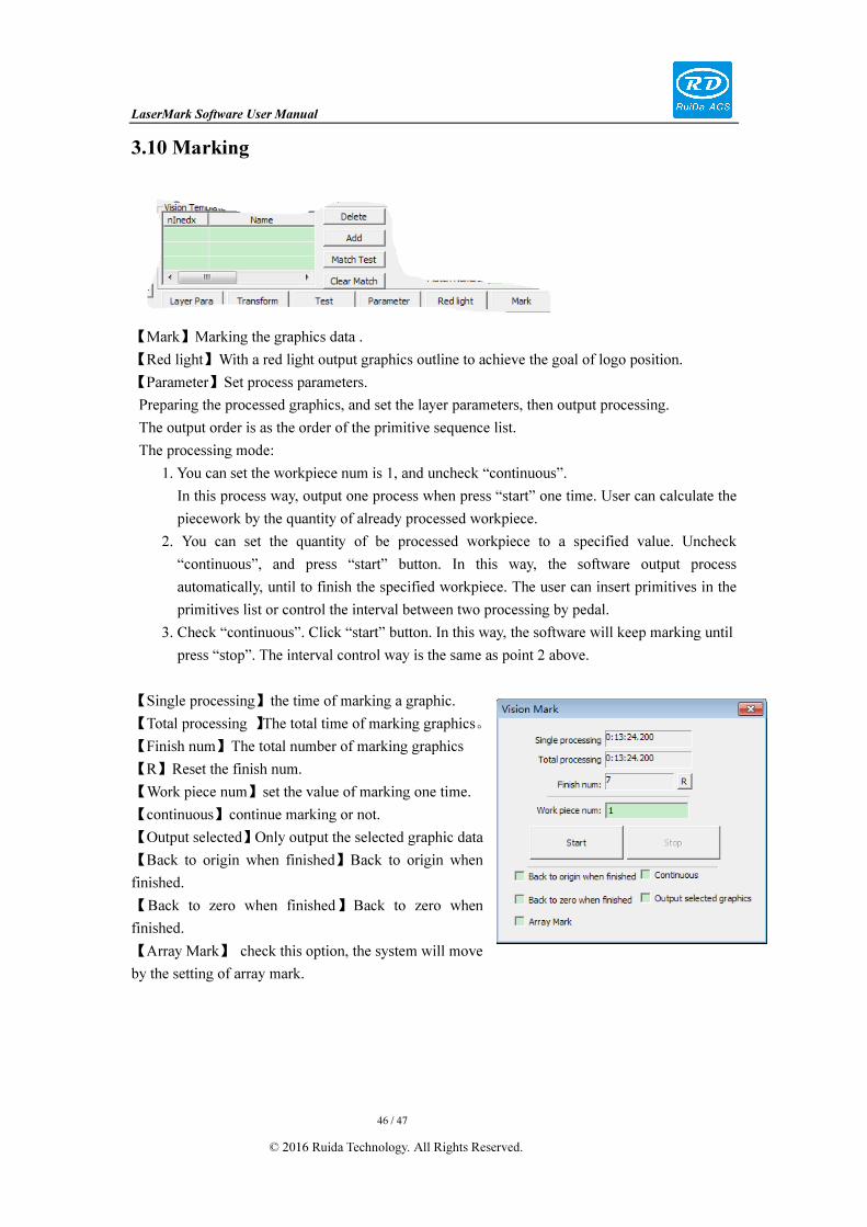
3.10 Marking
【Mark】Marking the graphics data .
【Red light】With a red light output graphics outline to achieve the goal of logo position.
【Parameter】Set process parameters.
Preparing the processed graphics, and set the layer parameters, then output processing.
The output order is as the order of the primitive sequence list.
The processing mode:
1. You can set the workpiece num is 1, and uncheck “continuous”.
In this process way, output one process when press “start” one time. User can calculate the
piecework by the quantity of already processed workpiece.
2. You can set the quantity of be processed workpiece to a specified value. Uncheck
“continuous”, and press “start” button. In this way, the software output process
automatically, until to finish the specified workpiece. The user can insert primitives in the
primitives list or control the interval between two processing by pedal.
3. Check “continuous”. Click “start” button. In this way, the software will keep marking until
press “stop”. The interval control way is the same as point 2 above.
【Single processing】the time of marking a graphic.
【Total processing 】The total time of marking graphics。
【Finish num】The total number of marking graphics
【R】Reset the finish num.
【Work piece num】set the value of marking one time.
【continuous】continue marking or not.
【Output selected】Only output the selected graphic data
【Back to origin when finished】Back to origin when
finished.
【Back to zero when finished】Back to zero when
finished.
【Array Mark】 check this option, the system will move
by the setting of array mark.

LaserMark Software User Manual
47 / 47
© 2016 Ruida Technology. All Rights Reserved.
Thank you very much for using the product from Shenzhen RuiDa Technology!
All parts of this manual description, all rights reserved by Shenzhen RuiDa Technology Co., Ltd.
Without our permission, any company or individual shall not reprint, copy or distribute the content
related to this product manual. We keep the rights to revise or update the contents without notice.
If any comments and suggestions please feel free to contact us.
Phone: 0755-26066687 Fax: 0755-26982287
Website: www.rd-acs.com
Address: 1B-1, Building 5, Tian'an Nanyou Industry Area,
Dengliang Road, Nanshan District, Shenzhen, P.R.C.