Embed Size (px)
Citation preview

SM-MP5
LASERMARK GIZMO
MP5
SERVICE MANUAL 2003, rev. 01

SM-MP5 2
WARRANTY COVERAGE
This Lasermark product is warranted to the original purchaser to be free from defects in workmanship and material. CST Corporation will repair or replace any defects, which may develop under normal and proper use, storage, and handling of the product. The product warranty periods are included in the warranty insert. CST must be allowed to make the changes necessary for instrument repair. Our goal is 5 days to repair and return the product. To validate the warranty the product delivered, shipped prepaid, to CST must be accompanied by a proof of date and place of purchase. This warranty is not subject to misuse, abuse, assignment, or transfer. The exclusive remedy under any and all warrants or implied, is limited to repair and or replacement as provided herein, and CST shall not be liable for damages from loss or delay of equipment uses, consequential, or incidental damages.
WARRANTY REGISTRATION
WARRAWARRANTY REGISTRATIONNTY REGISTRATION Model Name/Number: ______________ Serial Number: _____________ Date of Purchased:_________________ Company Name:_____________ Contact/Title:______________________ Comments or Suggestions: __________________________ Address:__________________________ __________________________ __________________________ City:____________________ __________________________ State/Providence:_________________________ Zip:______________________ Phone/Fax:____________________ Dealer Name/Location:_______________
What influenced you to purchase this equipment?
_Owned other CST Equipment _National ad
_Saw at trade show _Local dealer ad
_Recommended by someone _Dealer
-Other:_________________________________________________

SM-MP5 3
Tracer____________________________________ 90 Days
Laser Rail Level_______________________________ 90 Days
8” Torpedo Level______________________________ 90 Days
58-Gizmo____________________________________ 90 Days
Gizmo II-III __________________________________ 90 Days
Gizmo Lite _________________________________ 90 Days
Laser Plumb Bob______________________________ 90 Days
Laser Detectors _______________________________ 1 YEAR
Automatic Level ______________________________ 5 YEAR
Magnetic Locator _____________________________ 5 YEAR
Wizard Rotary Lasers__________________________ 1 YEAR
LM100, 200, 300______________________________ 2 YEAR
MP5 _______________________________________ 1 YEAR
LMH, LMHC/GR, LMH600_____________________ 2 YEAR
54-203BU___________________________________ 3 YEAR
LM400______________________________________ 2 YEAR
LM500______________________________________ 2 YEAR
DGT10______________________________________ 1 YEAR
Updated Warranties

SM-MP5 4
I. EXTERNAL CHECK.....................................................................................5-6
II. INTERNAL CHECK: REMOVAL OF MAIN HOUSING................................7-8
III. CIRCUIT BOARD UPPER...............................................................................9
IV. CIRCUIT BOARD LOWER............................................................................10
V. REMOVE GIMBAL ........................................................................................10
VI. REMOVE LOWER CIRCUIT BOARD ASSSEMBLY....................................11
VII. LASER DIODE...............................................................................................11
VIII. REMOVE LASER DIODES ..........................................................................12
IX. PRE CALIBRATION......................................................................................12
X. CALIBRATION ......................................................................................... 14-16
XI. MAIN DIODE SUB ASSEMBLY....................................................................17
XII. PRE BALANCE ........................................................................................ 18-19
XIII. ADJUST DAMPER ........................................................................................20
XIV. BALANCE......................................................................................................21
XV. INSPECTION .................................................................................................22
XVI. PARTS LIST ..................................................................................................23
XVII. SWITCH CIRCUIT BOARD PRINT ...............................................................24
TABLE OF CONTENTS

SM-MP5 5
TROUBLESHOOTING I. EXTERNAL CHECK 1) Instrument fails to produce dot when switch button is pressed on.
A. Check batteries for proper voltage and proper positioning. Replace blank battery door with new door with battery diagram.
B. Attach power supply to battery contacts. If instrument now lights, trim excess plastic from battery contact and clean with alcohol.
C. Instrument still fails to light, go to Internal Check (page 7). 2) Instrument side window is broken replace Housing Sub-Assembly (Left Housing Sub-
Assembly 58-6413 Figure A) (Right Housing Sub-Assembly 58-6414 Figure B). 3) Front, Top, and Bottom Windows are separate sub assemblies that may be replaced. Note: If gasket is loose-remove old adhesive. Apply new 2-sided adhesive (58-6513).
Figure A Left Housing Sub Assembly 58-6413 Left Housing Sub Assembly
58-6298 Magnet Bracket Sub Assembly
58-6175 Battery Contact DBL W/Springs
58-6174 Battery ContactSingle Button
W/Springs
57-4109 Black Wire 4.45 Length
57-6287 Battery Clip
Single “AAA”

SM-MP5 6
Figure B Right Housing Sub Assembly
58-6161 Lock Arm
58-6414 Right Housing Sub Assembly
58-6287 Battery Clip
Single “AAA”
58-6157 Switch
58-6170 Battery Contact Single Button
58-6171 Battery Contact
Double Button
51-18516 Sensomatic

SM-MP5 7
II. INTERNAL CHECK 1) REMOVAL OF MAIN HOUSING
A. Remove rubber bumper. Figure C
B. Remove (4) four (57-3758) #2 X ¾” lg torx pan head screws. C. Remove caution label and cut or remove serial # label inside battery compartment. D. Pull Housing Assembly apart.
2) Check power to (58-6159) Main Circuit Board Assembly.
A. Connect positive power supply to single button positive battery contact and connect negative (ground) power supply to ground connect pad (J3) on main board (Figure E). This checks battery contact wire and solder connections. If the instrument still fails to light continue through processes that check solder connection on switchboard, upper board, lower board, and spring connection.
B. Check switch and laser connections on main board.
58-6414 Right Housing Assembly will have everything inside it.
Figure D
58-6415 Front Window Assembly
58-6305 Bottom Window Assembly
58-6426 Bumper Assembly

SM-MP5 8
3) Check (58-6302) Switch Circuit Board Assembly (Figure F). 4) See if solder is connected well.
5) Check solder on Upper (58-6299) Circuit Board Upper Sub-Assembly. 6) If needed replace, follow process.
Check for solder
Wires are connected inside
Figure E
Figure F
Figure G
Laser Should Light
58-6159 Circuit Board Assembly, Main
Power Supply
Power Supply
Refer to Drawing 58-6302 for Placement of
leads in connector housingPage 24
Hot glue over soldered joints to add strength

SM-MP5 9
7) Check (57-5851) Connector Wire making sure it has a good connection. 8) If not go to next process. III. Replace the (58-6151) Circuit Board Upper. 1) Reheat solder that holds (57-5851) Connector Wire to Circuit Board.
2) Pull up (57-5851) Connector Wire and re-solder to J2 on
board once again. Leaving ¼” trim off excess wire.
3) Do Step 2 to J1 4) Check for good connection. 5) Reverse procedure to re-assemble. 6) If not go to next process.
Pull up on 57-5851 Connector Wire
Solder risen on the 57-5851 Connector Wire
Solder J2
Solder J1
RE-Solder the Connector Wire
Figure H
Figure I

SM-MP5 10
IV. Replace Circuit Board Lower Note: A range capable of the balance process for the MP5 is necessary for this
procedure. 1) Remove (58-6300) Yoke Sub Assembly
A. Heat up the solder on the (57-5851) Connector Wire B. Loosen (2) 58-6189M2x.4x4mm lg soc hd cap screws C. Remove (2) 58-6164 Gimbal pins D. Remove 58-6300 Yoke Sub-Assembly
V. Remove (58-6181) Gimbal 1. Loosen (2) 58-6189 M2 x .4 x 4mm lg. Soc. HD cap screws. 2. Remove (2) 58-6164 Gimbal pins. 3. Remove 58-6181 Gimbal
58-6189 M2x.4x4mm lg soc hd cap screw
58-6164 Gimbal Pin
58-6181 Gimbal
58-6189 M2x.4x4mm lg soc hd cap screws
Heat up solder remove 57-5851 Connector Wire
58-6164 Gimbal Pin
(58-6180) Yoke
58-6299 Circuit Board Upper Sub-Assy
Figure J
Figure K

SM-MP5 11
VI. Remove (58-6411) Lower Circuit Board Assembly 1. Remove (2) 58-6189 M2x.4x4mm lg ph pan hd screws 2. Remove 58-6411 Lower Circuit Board SA. Replace with new one 3. Reverse procedure for re-assembly.
VII. Laser Diode – Non-working Attach power supply to red and black wires coming out of back of diode body assembly. If one diode fails to light check solder connections behind black plug. If diode must be replaced, you must have a range capable of calibration of the diode body assembly.
1. Plug Placement
A. Remove black plug from back of diode body. B. Pull red and black wires through plug and desolder leads of failed diode.
Figure M
58-6411 Lower Circuit Board Sub-Assembly 58-6189 M2x.4x4mm
lg. ph hd screw
Figure L
Plastic Washer on bottom side of board at
screw hole
Pull wires through holes
in plug
Plug in Diode body

SM-MP5 12
VIII. Removal - Laser Diode 1) Remove Diode from 58-6182 Main Diode Body 2) Loosen 6 setscrews of failed diode and remove diode from diode body. 3) Reverse procedure for reassemble IX. Pre-calibration – Note: Must check 58-6196/58-6169 screws. 1) Place Diode Body in fixture, assuring body is straight, and clamp is tight. 2) Connect power supply clips to lead wires 3) Shooting beam at target adjust the beam by turning the 58-6197 setscrew in or out bringing
the beam into alignment. 4) Repeat Step C for all five lasers diodes adjusting each beam with the
adjacent target. 5) After tightening (20) screws each laser must hit the center of the target
NOTE: ALL SCREWS MUST BE TIGHT.
Figure N
Diode Body
Text Fixture
Hook Red Wire
Hook Black Wire
Clamp

SM-MP5 13
Figure O Assure all screws are tighten
Figure P
Target
Target Center, Place Diode on Black Circle
58-6169 M2 X.4X3MM LG
Soc Set Screw
58-6197 Set screw for
650NM Diode

SM-MP5 14
X. Calibration 1) Place 58-6292 Diode Body Sub-Assembly in fixture. 2) Hook power supply to Diode Body Leads. 3) With front laser facing the target center the dot on the target 4) Adjust the dot into the target by tightening/loosening the (58-6197) M3 X .5 X 5MM lg soc
set screw. A. “Top” (58-6197) Screws: By tightening the screw the dot goes up
Loosening the screw the dot goes down. B. “Bottom” (58-6197) Screws: By tightening the screw the dot goes down.
Loosening the screw the dot goes up. 5) Set the Digital Theodolite at 00.00 degrees. 6) Move the Digital Theodolite 90 degrees. 7) Adjust the dot to the target as in Step 4. 8) Move the Digital Theodolite back to 00 degrees to make sure the dot is still on the target. 9) If necessary re-adjust the dot. 10) Repeat Step D and E. 11) Move the Digital Theodolite 180degrees. 12) Adjust the dot to the target as in Step 4. 13) If necessary to re-adjust the dot repeat Step 4 and 5. 14) All three sides should all be on the target area. 15) Roll the Top Plumb on itself by adjusting the (4) screws. 16) Make sure all screws are tight. 17) Roll the Bottom plumb on itself by adjusting the (4) screws. 18) Make sure all the screws are tight. 19) Recheck all Dots again making sure they are correct.
Figure Q
Fixture
Power Supply
Power Supply
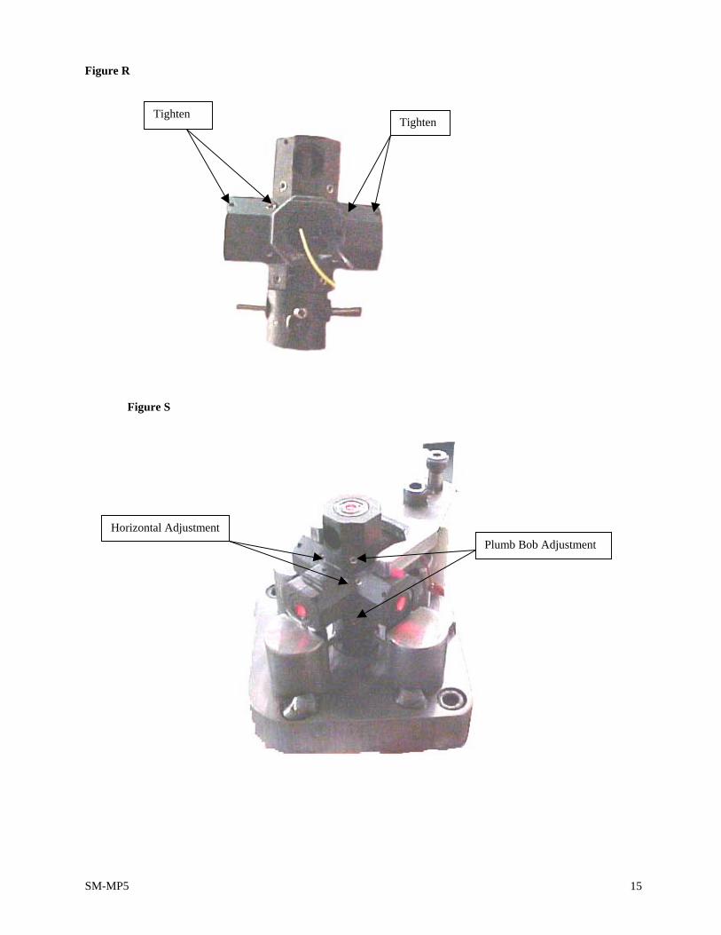
SM-MP5 15
Figure R
Figure S
Tighten Tighten
Plumb Bob Adjustment Horizontal Adjustment

SM-MP5 16
Figure T
Dot Centered on Target Target
Diode Body Sub-Assembly
Text Fixture

SM-MP5 17
XI. Full Main Diode Sub-Assembly 1) Place 58-6411 Lower Circuit Board Sub-Assembly on 58-6182 Main Diode Body. 2) Solder 57-4109 Black 28AWG 1 inch wire to the 58-6411 Lower
Circuit Board Sub-Assembly (Figure U) 3) Solder the 57-4108 Red 28AWG 1inch wire to 58-6411 Lower Circuit Board Sub-Assembly. 4) Connect to power supply checking for power to the Diodes. If not Repeat steps A-C. 5) Add (2) 58-6178 Counterweights – one at front and one at right 6) Add 58-6189 Damper and (4) 58-6189 M2 X .4 X 4MM lg soc HD cap screws
Figure U
Figure V
Solder wires
58-6185 Damper
58-6189 M2 X .4 X 4MM Lg. Soc. HD Cap Screw
58-6185 Counter Weight

SM-MP5 18
XII. Pre-Balance 1) Check that 58-6189 M2 X .4 X 4MM lg soc HD cap screws are tight on the 58-6185 Damper
(Figure S). 2) Place 58-6304 Full Main Diode Assembly into fixture (Figure X). 3) Hook power supply to female connector. 4) Check Y-axis for small amounts of movement noting movement of Gimbal by slightly
moving body back and forth. 5) Shoot the front laser dot on target. 6) Tighten Yoke screws. 7) Set balance on X axis by tightening/loosing the back 58-6164 Gimbal Pin bringing dot to
reference point on target (Bring screw out to raise the diode; screw in to lower the diode) 8) Wedge a screwdriver between Gimbal and diode adjusting the yoke screw. 9) Remove wedge from between Gimbal and diode. 10) Recheck dot on target at reference point 11) Turn assembly to side checking Y axis at reference point on target. 12) Recheck for dot movement on target by wedging a screwdriver between Gimbal/diode and
releasing (If dot does not return to the point of reference you may need to adjust damper).
Figure W
Gimbal
Connect to Power
Push Main Body to check for Gimbal Movement
Counter Weights
Fixture
Figure X
Check for (4) Screws in Damper

SM-MP5 19
Figure Y
Figure Z
Yoke Screw
Place Wedge between Gimbal and Diode
Fixture
Soc Hd Cap Screw
Gimbal Pin
Gimbal
Yoke
Y Axis
X Axis

SM-MP5 20
XIII. Adjusting Damper 1) Place assembly with side of damper that needs adjusted facing.
down in Damper Fixture. 2) Tighten assembly in place using the knob on top of fixture. 3) Loosen (4) Cap Screws in the damper. 4) Retighten fixture knob. 5) Retighten (4) Damper Screws. 6) Remove Assembly from fixture . 7) If necessary to adjust the damper recheck balance. 8) All weights should be adjusted equally from the body. 9) If necessary, back weight may be adjusted to bring balance into the reference point.
Figure 1
58-6155 Circuit Board Assembly
Knob

SM-MP5 21
XIV. Balance NOTE: BEFORE USING THE ANGLE FINDER SET FIXTURE TO ZERO AND MAKE SURE THE DAMPER SCREWS ARE TIGHT.
1) Place assembly on fixture 2) Connect to power supply 3) Check play on Y Axis by gently gliding the Gimbal back and forth 4) Tighten yoke screws 5) Check short shot on all (3) dots, making sure there is Gimbal movement. 6) Shoot laser to target 7) Check for bearing stabilization by inserting a wedge between the bearings and Gimbal 8) Remove wedge and check for free movement of the Gimbal 9) Retighten Gimbal screws 10) Check Gimbal movement by slightly swinging assembly back and forth 11) Check balance by shooting dot to target 12) Adjust Counter Weight (screw Counter Weight out to lower dot; screw Counter Weight in to
raise dot) 13) Check each laser by repeating steps E through L 14) Check tilt by loosening knob and tilting test fixture forwards 15) The dot on (3) each laser should hit in same spot on target (Dot may hit halfway on top or
bottom of target) 16) Recheck tilt on each laser by tilting fixture in opposite direction 17) Adjust the fixture back to zero position, level as set with the Angle Finder, recheck dots on the
target Figure 2
Angle Finder Set at 0
Balance Fixture

SM-MP5 22
XV. Inspection
1. A. Instrument does not blink when Sensor Spring touches Sensor Board – Replace Main Board (58-6159).
B. Sensor Spring (58-6405) corroded – Replace. 2. Instrument blinks when Sensor Spring does not touch Sensor Board – Replace Main Board
(58-6159). 3. Instrument turns on before switch is fully unlocked:
A. Check strength of Compression Spring (57-5252) between the two switch parts (58-6165/58-6166).
B. Bend front half of metal arm on Switchboard (58-6157) upward at a 30º angle. 4. Tilt function failure - Instrument must be updated with sensor spring and sensor board to
replace the optional sensor. 5. A. Pendulum does not move freely – Check for loose components causing interference
between damper and magnets. B. Magnet loose from Magnet Bracket – Reattach Magnet using a new Adhesive (58-
6420). C. Magnet bracket loose – Replace housing half.

SM-MP5 23
XVI. Parts List
Part # Description Located
58-6413 Left Housing Sub Assembly Page 5 Figure A
58-6414 Right Housing Sub Assembly Page 6 Figure B
58-6415 Front Window Assembly Page 7 Figure D
58-6305 Bottom Square Glass Sub Assembly Page 7 Figure D
58-6147 Battery Door
58-6159 Circuit Board Assembly, Main Page 8 Figure E
58-6302 Switch Circuit Board Sub Assembly
58-6300 Yoke Sub Assembly
58-6301 Circuit Board Back Sub Assembly Page 11 Figure L
58-6163 650NM Laser Diode Module
57-5851 Connector Wire Page 10 Figure J
58-6411 Lower Circuit Board Sub Assembly
58-6299 Circuit Board Upper Sub Assembly Page 10 Figure J
58-6181 Gimbal Page 10 Figure K
58-6180 Yoke Page 10 Figure J
58-6293 Bumper Foot
58-6291 Foam Rubber Strip
58-3758 #2 X ¾” LG Torx Pan Head Screw
58-6148 M1.6 X .36 X 3MM Lg Ph Pan HD Screw
58-6189 M2 X .4 X 4MM Lg Soc Hd Cap Screw
58-6164 Gimbal Pin Page 10 Figure J
58-6198 Bearing
58-6170 Battery Contact, Single Button Page 6 Figure B
58-6171 Battery Contact, Double Button Page 6 Figure B
58-6287 Battery Clip, Single “AAA” Page 5 Figure A
58-6174 Battery Contact Single Button W/Spring Page 5 Figure A
58-6175 Battery Contact Double Button W Spring Page 5 Figure A
58-6307 Battery Contact W/O Spring, Sub Assembly Page 5 Figure A
58-6425 Battery Contact W Spring, Sub Assembly
58-6295 M4 X .7 X 6MM Lg Slotted Cheese Hd Machine Screw
58-6426 Bumper Assembly Page 7 Figure C

SM-MP5
A
24


![Consequential Damages in CISG Context2007] CONSEQUENTIAL DAMAGES IN CISG CONTEXT 67 (i.e., the substantive or procedural standard applied by the court or tribunal in the jurisdiction](https://img.pdfslide.us/doc/110x75/606366bdb7170949472b16cd/consequential-damages-in-cisg-context-2007-consequential-damages-in-cisg-context.jpg)