Embed Size (px)
Citation preview

1
Laser welding of dissimilar aluminium alloys with filler material
Luís Filipe Amaro Pinto
Instituto Superior Técnico – Technical University of Lisbon – Portugal
September 2008
Abstract
The aluminium alloys are materials with great potential because of its high strength and
low weight. However, the welding of dissimilar aluminium alloys is difficult in autogeneous
welding, due to these alloys are welding with filler material.
The present work focus on welding dissimilar 6xxx series, and 5xxx with 6xxx series (the
main components of these alloys are Al, Mg and Si), with filler wire. These alloys have particular
application in the aerospace, military and information technology industries.
A Nd:YAG laser, with a maximum pulsed power in PW mode of 5 kW was used to
perform the welds. Fillers wires 4047, 4047A, 4043 and 5356 were tested for the different
combinations of base materials. This research aimed at the selection of the filler wire that
presents better performance in welding dissimilar Al alloys. The quality of welds was tested by
macro graphic and microstructure analysis. Scanning electron microscope and hardness tests
were also performed.
The results indicate that with filler wires with compositions with low magnesium and high
silicon contents it is easier to achieve good quality welds though attention needs to be payed to
the required mechanical to assure the adequate service performance of the part.
For the base materials studied, it is possible to conclude that the filler wire 4047
presented the best results in welding of dissimilar aluminium alloys series 6xxx and 5xxx.
Key-Words
Laser welding; Pulsed Nd:YAG Laser; Filler wire; Dissimilar aluminium alloys; Al 5xxx; Al 6xxx
1 Introduction
The combination of light weight good mechanical properties makes aluminium alloys
increasingly interesting employed in many important manufacturing areas, such as the
automobile, aeronautics and military industries. Using aluminium alloys in manufacturing leads
to the need of the development of assembly processes, especially welding, where conventional
techniques have shown their limitations. Laser welding therefore, has progressively attracted
the attention of the industrial and research communities during the last decade as a process
with potential to overcome the problems faced in conventional welding processes. Laser
welding of aluminium alloys, can nevertheless generate defects, such as porosity, cavities and
hot cracking which need to be avoid [1;2].
2 Experimental strategy
To clarify the phenomenon under review, any general approach should be designed with
the aim of establishing from the outset the appropriate response functions and contributory
factors. In this case, the “product”, that is, the final result is the weld, which is the direct result of
the solidification of the molten pool (Figure 1). The characteristics of the weld can be

2
appreciated from different points of view: technological, aesthetic, economic, etc. As for laser
welding, the factors influencing the response functions that characterize the weld can be put
into two categories, namely, phenomenological factors and operating factors (Figure 1).
Figure 1 – Functional design of laser welding processes
Among the operating factors influencing the shape and properties of the molten pool,
and, consequently, the properties of the weld, absolute and relative factors can be identified.
The absolute factors relate to the following:
The laser beam: its wavelength, power, power distribution, operating mode, spot size.
The welded materials: their chemical composition, properties, microstructure, geometry.
The shielding gas: its composition, flow rate, flow configuration.
The added material: its chemical composition, properties, geometry, shape.
The relative factors are the following:
The position of the laser beam relative to the welded materials, to the shielding gas
stream and to the added material.
The angle and distance relative to the welded materials.
The movement between the laser beam and weld material (welding speed).
The movement between the added material and the laser beam (feed rate of added
material).
The objective of the present work is welding dissimilar 6xxx series and 5xxx with 6xxx
series and analyse a diversity of cases in order to define optimal procedures to the selection of
the filler wire for welding these materials. The process of adding filler material is manual.
Fillers have two functions: first, they are used to bridge wide or irregular gaps in the joint,
reducing the amount of work required to prepare the seam. Second, the fillers add elements to
the molten metal in order to alter the properties of the material in specific ways. Such properties
include suitability for welding, strength, durability, and corrosion resistance [3].
The cases studied were welding of LM 25 alloy to 6061 with filler wire 4047, welding of
6063 alloy to 6082, testing four types of filler wires, 4047, 4047A, 4043 and 5356. The last case
was welding of 6060 alloy to 5754 with filler wire 4043 and 4047.
In order to evaluate the quality of the welds it macro graphic and micro structural analysis
was done by optical and scanning electron microscope and hardness was measured with
Vickers indenter.
Operating factors
• Laser
• Power
• Base material
• Added material
• Shielding gas
• Position and movement
• Welding speed
Welding process
• Molten pool
• Geometry
• Chemicalcomposition
• Shape
• Temperature
• Cooling speed
• Shielding gas
• Tensions
Result: the weld
• Shape
• Properties
• Defects

3
The experiments on laser welding were performed in the company Carrs Welding
Technology Ltd (CWT), in Kettering, England. This company is specialised in laser welding of
dissimilar aluminium alloys, repairing of moulds and tools and production of high
quality/precision parts.
This work was done using a pulsed Nd:YAG laser, model HL 124 P, from TRUMPF, with
a maximum pulse power of 5000 W in two different work-stations (Figure 2).
Figure 2 – Work-stations used in this work (CWT)
Materials
The chemical composition of base materials and fillers wire used in this work are
presented in Table 1.
Chemical composition [Wt. %]
Component Si Fe Cu Mn Mg Cr Zn Ti Al
LM 25 base metal
6,5-7,5 0,5 0,1 0,3 0,2-0,6 - 0,1 0,2 90,15-91,55
6061-T6 base metal
0,4-0,8 0,7 0,15-0,40
0,15 0,8-1,2 0,04-0,35
0,25 0,15 95,8-98,6
6063-T6 base metal
0,2-0,6 0,35 0,1 0,1 0,45-0,9
0,10 0,1 0,1 97,5
6082-T6 base metal
0,7-1,3 0,5 0,1 0,4-1,0 0,6-1,2 0,25 0,2 0,1 95,2-98,3
6060 base metal
0,3-0,6 0,1-0,3
0,1 0,1 0,35-0,6
- 0,15 0,1 97,8
5754-O base metal
0,4 0,4 0,1 0,5 2,6-3,6 0,1-0,6 0,2 0,15 93,6-97,3
4047 filler 11-13,5 0,6 0,05 0-0,5 0,05 - 0,1 0,1 86,45-86,75
4047A filler 11,0-13,0
0,6 0,30 0,05 0,05 - 0,20 0,15 85,3-89,0
4043 filler 4,5-6,0 0,8 0,30 0,05 0,05 - 0,10 0,20 92,3-95,5
5356 filler 0,25 0,4 0,10 0,05-0,2
4,5-5,5 0,05-0,2
0,10 0,06-0,2
92,9-95,3
Table 1 – Chemical composition of the aluminium alloys [4]
Fillers wire used were tipes 4047, 4047A and 4043 with 0,38 mm (0,015’’) diameter and
5356 with 0,64 mm (0,025’’) diameter.
Shielding gas used was argon injected coaxially with the laser beam.
3 Results and discussion
The results obtained will be divided according to the combinations of base material used
in the welds.

4
3.1 Welding – LM 25 alloy with 6061
Cast aluminium alloys with the designation LM 25 (A 356.0) and 6061 alloy were welded
with filler wire 4047.
In this case are tested two types of design of joint like show in Figure 3 in order to
evaluate the design that assure the reliability of the parts.
Figure 3 – Design of joint; joint A and B respectively
The parameters selected are presented in Table 2. The values of these parameters are
the ones used by the company to perform dissimilar aluminium welding.
The pulse overlapping (u) indicates to which degree the weld point of a laser pulse
overlaps the weld point of the previous pulse. The pulse overlapping determines the uniformity
of the welding structure. Practical values range typically from 60 % to 85 %. The pulse repetition
frequency and the pulse overlapping influence the machining time at welding, so from data
found in the literature survey it was possible to estimate values of manual welding speed for all
welds [5].
Autogenous passes
Filler passes
Smoothing run
Power [kW] 2,5 2,5 2,5
Pulse duration [ms] 5,2 5,2 5,2
Frequency [Hz] 6,5 8,0 8,0
Spot size [mm] 0,8 0,85 1,2
Welding speed u= 60% [mm/s] 2,08 2,72 3,84
Welding speed u= 85% [mm/s] 0,78 1,02 1,44 Table 2 – Welding parameters for LM 25 alloy with 6061
Macro graphic and microstructure analysis
Optical microscopy and scanning electron microscopy (SEM) were used to perform
microstructrual examination. The aim of macro graphic was to find welding defects, such as
pores and cracks, while the microstructure analysis’ aim was to allow understanding the
structure of the fusion zone.
Figure 4 – Cast alloy LM 25; Macro graphic joint A; 6061 alloy; Macro graphic joint B
The joint of configuration “A” (Figure 4) lead to the lack of penetration, so another
configuration was tested as shown in Figure 3-B. The main problem present in the welding of
a
)
b
)
Laser Laser

5
these alloys was micro cracks in the interface of fusion zone and base material 6061 and
porosity like show Figure 5 a) and b). Micro porosity was caused by hydrogen rejected from the
solid metal on solidifying. Potential hydrogen sources were moisture contaminants and hydrated
oxides on the surface of the parent metals and filler wires.
Figure 5 – a) Interface fusion zone with 6061 alloy; b) Porosity in fusion zone
Micro cracks appear in the 6061 alloy interface due to the high level of magnesium in this
alloy. This defect wasn’t found in connection to the LM 25 cast alloy, because of the high
content of silicon, which facilitate the weldability due to the similar levels of silicon present in
filler 4047. In LM 25 the removal of the cast oxide layer, which is a great source of hydrogen,
oxide and hydroxide compounds, reduces drastically the micro porosity content by modifying
the conditions of germination and growth of occluded bubbles [2]. This problem is avoid with
improve gas shielding. A possible solution is to lower the temperature of shield gas (to around
223 K) [6]. Another way to reduce the porosity is increasing the power and consequently the
time of solidification thus allowing the hydrogen to escape to the atmosphere. Any source of
hydrogen, such as oil, moisture on the surface or hydrated oxides should be eliminated in order
to be able to obtain welds free of porosities. It is also essential to proceed to the removal of the
oxide layer on surface. Surface preparation, especially laser cleaning, reduces the hydrogen
sources responsible for micro porosity generation, and produces a nearly total suppression of
pores in fusion zone [2]. However this solution is quite expensive so an alternative is to remove
the oxide layer with different surface preparations as mechanical polishing or with a simple
acetone degreasing.
SEM-Analysis
Simple metallurgical observations (micrographs) and SEM analysis coupled with energy
dispersive X-ray spectroscopy (EDS) techniques were carried out to analyse the chemical
composition of the materials, with the aim to perform microstructrual examination.
Chemical composition [Wt. %]
Component Base materials Filler wire
LM 25 6061 4047
Si 16,32 2,00 13,08
Fe 0,40 0,29 0,31
Mg 1,94 2,91 1,73
Al 81,00 94,80 84,66 Table 3 – Energy dispersive X-ray (EDX) microanalysis (in wt.%)
The LM 25 cast, due to a high Si content, is expected to have a greater fluidity in liquid
regime. More, silicon tends to reduce the solubility of hydrogen in liquid aluminium and
decrease porosity [2].

6
The contents of silicon and magnesium verified for 6061 alloy are slightly higher than
typical values. The high levels of magnesium are often the cause of micro cracks and porosity,
observed in optical microscopy in the interface of the fusion zone in 6061 alloy (Figure 5-a).
These high levels of magnesium observed in all alloys, can be the cause for the high
porosity verified, because in alloys with high levels of magnesium the solubility of hydrogen in
the molten aluminium during the solidification. During the solidification of a large amount of
hydrogen creates bubbles in the solid-liquid interface, interacting with the magnesium [7].
Figure 6 - SEM micrographs of interface LM 25 with filler wire 4047and interface 6061 alloy with 4047
respectively
Various types of as-cast morphologies are obtained, depending on whether the alloy
content is above, below, or near the eutectic composition. This is shown for the aluminium-
silicon system hypoeutectic aluminium silicon alloys like LM 25 (Figure 6). (i.e., those with
alloying contents below the eutectic composition of 12.6 wt% Si) have a network structure of a
dispersed second in a solid-solution rich in aluminium [8].
The Al-Mg-Si system is the basis for the 6xxx alloys containing magnesium to provide
precipitation hardening. At low magnesium contents, elemental silicon may be presented as
second-phase particles. As magnesium increases, both silicon particles and equilibrium
hexagonal Mg2Si constituents may be present. At higher magnesium contents, only Mg2Si is
present [8;9].
The main results obtained in this analysis are summarised in Table 4.
Geometry A Geometry B
Surface Appearance Good Good
Penetration Incomplete Full
Porosity Few Many
Hot cracking Not present Not present
Hardness [HV1] 101 98
Table 4 – Results welding – LM 25 alloy with 6061
Both configurations have good quality of superficial appearance, but in this case the lack
of penetration was the predominant factor for acceptance of the welds as to ensure the
reliability of the part. A complete penetration was necessary to avoid a stress concentration that
could be catastrophic for the integrity of the weld, when in service conditions. So the
configuration selected for the welds is the configuration B which presents more penetration
because of the scarf done. Hot cracking is avoided with the filler wire 4047, due to the high level
of silicon presented in this alloy.
A surface preparation with mechanical polishing (220 and 800 grades SiC papers) or
simple acetone degreasing, reduces the hydrogen sources responsible for micro porosity
generation [2].
LM 25
Cast
4047
Alloy
4047
Alloy
6061
Alloy

7
Figure 7 – Hardness comparison between geometries
The value of average hardness is quite similar that was expected since the filler used was
the same for both configurations. The small difference was probably related to porosity.
(Although the shape of the indent did not indicate penetration in a pore, subsurface pores
reduce the dent resistance resulting in an increased indentation depth and thus in a lower
hardness value.)
3.2 Welding – 6063 alloy with 6082
During these experiences two types of aluminium alloys were also used: an aluminium
6063-T6 alloy in bar (length 4000 mm, width 3,2 mm e height 12,5 mm) and a aluminium 6082-
T6 in plate (length 350 mm, width 250 mm and height 3 mm). The filler wires used were 4047,
4047A, 4043 and 5356. The compositions of these aluminium alloys are presented in Table 1.
The configurations of joint tested were butt and fillet weld. A comparative analysis was made in
order to identify the better filler wire for welding these materials. The parameters select to
perform the welds are presented in Table 5.
Parameters Fillet weld Butt weld Units
Power 3,2 2,2 kW
Pulse duration 5,0 6,0 ms
Frequency 7,0 6,5 Hz
Spot size 1,0 0,845 mm
Energy 16 17,3 J
Average power 112 - W
Heat input - 4027 J/cm2
Tension - 350 V
Welding speed (u=60%) 2,8 2,2 mm/s
Welding speed (u=85%) 1,05 0,82 mm/s
Table 5 – Welding parameters for 6063 alloy with 6082
Macro graphic and microstructure analysis
The butt welds done with wires 4043 and 5356 alloys broke during cutting for sample
preparation of the samples for metallographic analyse. The butt weld done with filler wire 5356
presented hot cracking during the welding.
Figure 8 – base metal 6082-T6; Butt welds with wire 4047; Butt weld with wire 4047A; base metal 6063-T6
80
90
100
110
120
130
-2,5 -2 -1,5 -1 -0,5 0 0,5 1 1,5 2 2,5
HV
1
Distance to the center [mm] Sample A Sample B
LM 25
4047
6063

8
Both samples showed lack of penetration at the root and lack of fusion between passes.
These problems were due to inefficient edge preparation of joint and incurred due to the
different geometry of base materials.
Figure 9 – Fillet welds, the wires used was 4047, 4047A, 4043 and 5356 respectively
The welds exhibited a good weld shape. Visual inspection and the metallographic
examinations didn’t reveal hot cracks with exception for 5356 alloy.
The weld obtained with filler 4047 didn’t present porosity in the fusion zone and showed
good fusion bond between the base alloys and filler material.
Filler wire 4047A produced a weld with no porosity, lack of fusion at the root of the
sample, as well as lack of bonding near the root and didn’t show porosity.
The welds with 4043 alloy show large number of pores, however with good penetration
and good fusion bond between the base alloys and fusion zone.
The weld with filler wire 5356 presents extensive cracking and porosity which don’t
assure the integrity of the joint. These large pores were particularly found in welds of Al–Mg
alloys and in joints made with filler alloys containing a higher amount of magnesium.
SEM-Analysis
The chemical compositions of the fusion zone deposited with 4047, 4047A, 4043 and
5356 fillers and base materials are shown in Table 6.
Chemical composition [Wt. %]
Component Base materials Filler wire
6063 6082 4047 4047 A 4043 5356
Si 2,17 1,69 12,97 11,59 16,16 3,32
Fe 0,50 0,31 0,50 0,35 0,40 0,20
Mg 2,66 2,38 1,84 1,92 - 4,74
Al 93.47 95,62 84,68 83,07 83,44 91,47
Table 6 – Energy dispersive X-ray (EDX) microanalysis (in wt.%)
The welds done with filler 4047 and 4047A presented values characteristic of a silicon
eutectic reaction. The results obtained with EDX confirm the similar chemical composition of
these wires. So the differences in the results obtained in welds are due to operational factors
such as different joint preparation.
The elevated levels of magnesium presented in all alloys are often the cause of micro
cracks, observed in optical microscopy. However, high levels of magnesium can increase the
strength and hardness of welded joints [3]. So, it was frequent the use of the filler wire 5356 to
obtain greatest strength but in this case it has been ineffective due to operational factors such
as power and welding speed. The filler wire 5356 presents’ best results in welds of alloys with
high level of magnesium as 5xxx alloys [10].

9
Figure 10 – SEM micrographs of interface 6063 alloy and fusion zone with wire 4047A; interface 6082
alloy and fusion zone with wire 5356
A homogeneous micro structure is observed for 6063 and 6082 as shown in Figure 10. At
low magnesium contents, elemental silicon may be present as second-phase particles. As
magnesium increases, both silicon particles and equilibrium hexagonal Mg2Si constituents may
be present. At higher magnesium contents, only Mg2Si is present [8].
Figure 11 – Hardness comparison between fillet welds
Comparing the hardness profiles of different joints it is seen that the base materials
showed a profile of hardness approximately constant. Filler wires 4047 and 4047A presented
similar behaviour as expected due to the similar chemical composition and mechanical
properties. Fillers 4043 and 5356 present similar hardness profiles. All fillers present a decrease
in the hardness of the heat affected zone (HAZ).
The hardness increased using silicon-rich filler wires. The highest values were
determined for welds made with the filler wire 4047A. The lowest values were measured for
joints welded using filler metals with high magnesium content.
In the case of heat-treatable alloys, the loss of precipitates in the welds and over aging in
the HAZ has been identified as the main cause of hardness reduction. This degradation is
caused by microstructural modifications associated with elevated temperatures experienced in
this zone. For heat-treatable aluminium alloys, the HAZ is distinguished by dissolution or growth
of precipitates.
Postweld heat treatment can also be used to improve the strength of the HAZ for heat-
treatable alloys. This may involve complete postweld solution heat treating and aging or
postweld aging only. Although the recovery of strength in the HAZ after postweld aging is less
than postweld solution heat treating and aging, there are advantages to postweld aging only [3].
The most important results achieved in this analysis are summarised in Table 7.
4047 4047A 4043 5356 Surface Appearance Good Good Good Good
Porosity Few Few Many Many
Hot cracking Not present Not present Not present Present
Hardness [HV1] 110 118 67 74
Table 7 – Results welding – 6063 alloy with 6082
50
70
90
110
130
-2,5 -2 -1,5 -1 -0,5 0 0,5 1 1,5 2 2,5
HV
1
Distance to the center [mm] 4047 4047 A 4043 5356
Wire
4047A
6063-T6
Alloy
6082-T6
Alloy
MA
5356 Wire
5356
6082
6063
10
The welds exhibited a good weld shape. Visual inspection as well as metallographic
examinations didn’t reveal hot cracks exception for 5356 alloy
The filler 4047 was the one with the best overall results. The results obtained with filler
4047 and 4047A confirm the similar chemical composition and mechanical properties of these
wires. So the differences in the results obtained in the welds are due to operational factors such
as different joint preparations.
Filler wire 4043 has led to acceptable quality welds though with tendency to present
porosity. Proper surface preparation of the parent material and protection of the filler metals
from humid environments can reduce pore formation in these welds.
Because of their narrow solidification temperature range, the 4xxx series filler alloys
provide excellent insensitivity to weld cracking but are not applicable for welding all aluminium-
base alloys. Because of the formation of large amounts of brittle magnesium-silicon (Mg2Si), the
4xxx series filler alloys are not applicable for welding the 5xxx series alloys containing
appreciable amounts of magnesium [3]. However high levels of silicon in the weld when using
the 4xxx series filler alloys result in darkening of the fusion zone in comparison to the base
metal after anodizing.
The performance of the filler wire 5356 with the parameters and equipment used proved
to be ineffective to obtaining reliable welds. Both welds, fillet and butt presented defects like
cracks and porosity. These problems are due to the tendency for hot cracking in welds of 5xxx
and 6xxx alloys. The 5xxx-series filler alloys, in particular, are susceptible to the hydration of
surface oxides, which can result in porosity [3].
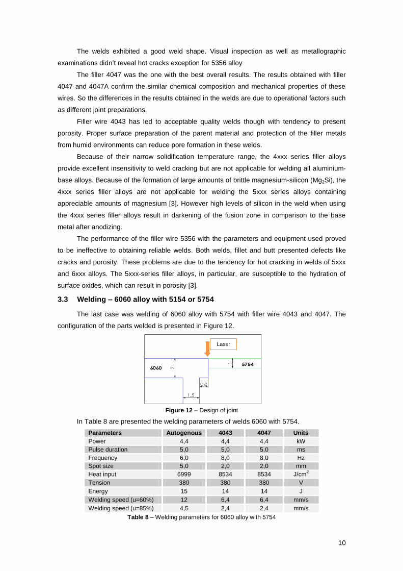
3.3 Welding – 6060 alloy with 5154 or 5754
The last case was welding of 6060 alloy with 5754 with filler wire 4043 and 4047. The
configuration of the parts welded is presented in Figure 12.
Figure 12 – Design of joint
In Table 8 are presented the welding parameters of welds 6060 with 5754.
Parameters Autogenous 4043 4047 Units
Power 4,4 4,4 4,4 kW
Pulse duration 5,0 5,0 5,0 ms
Frequency 6,0 8,0 8,0 Hz
Spot size 5,0 2,0 2,0 mm
Heat input 6999 8534 8534 J/cm2
Tension 380 380 380 V
Energy 15 14 14 J
Welding speed (u=60%) 12 6,4 6,4 mm/s
Welding speed (u=85%) 4,5 2,4 2,4 mm/s
Table 8 – Welding parameters for 6060 alloy with 5754
Laser
11
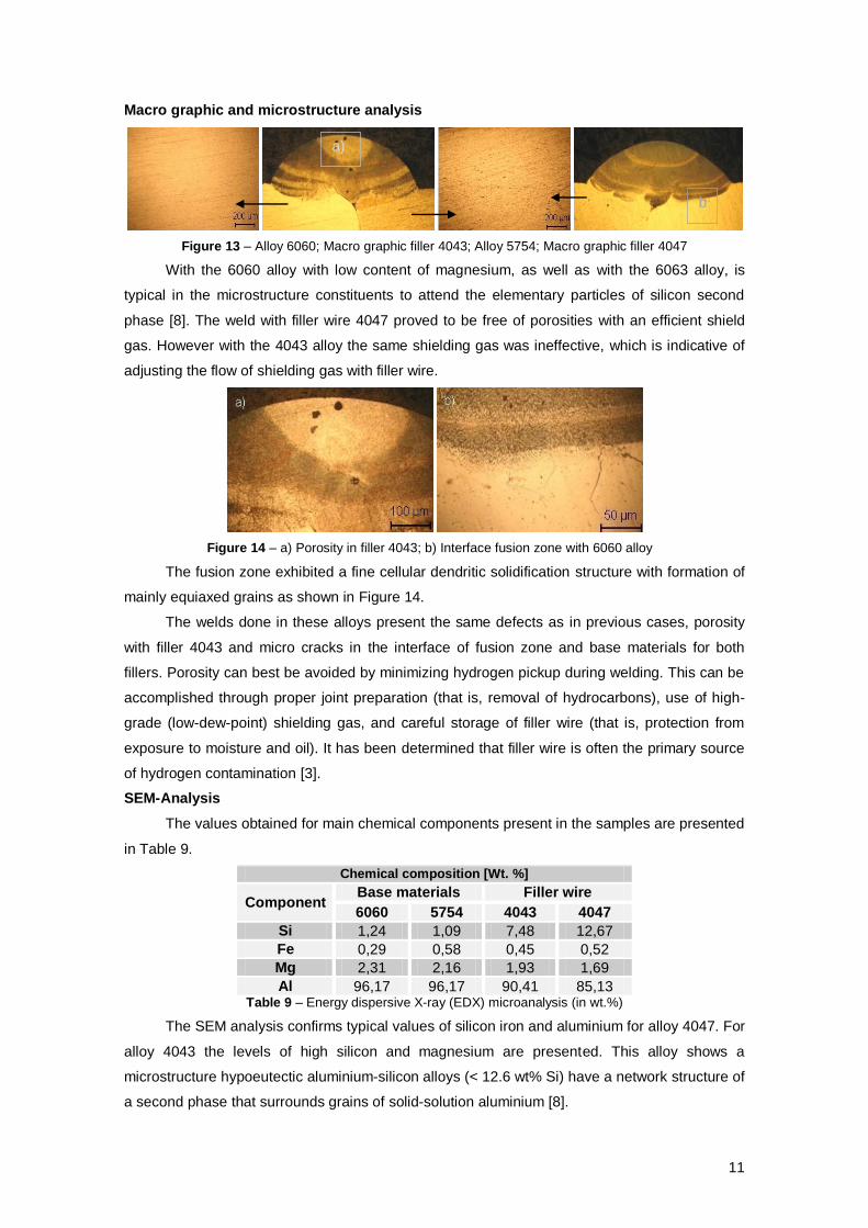
Macro graphic and microstructure analysis
Figure 13 – Alloy 6060; Macro graphic filler 4043; Alloy 5754; Macro graphic filler 4047
With the 6060 alloy with low content of magnesium, as well as with the 6063 alloy, is
typical in the microstructure constituents to attend the elementary particles of silicon second
phase [8]. The weld with filler wire 4047 proved to be free of porosities with an efficient shield
gas. However with the 4043 alloy the same shielding gas was ineffective, which is indicative of
adjusting the flow of shielding gas with filler wire.
Figure 14 – a) Porosity in filler 4043; b) Interface fusion zone with 6060 alloy
The fusion zone exhibited a fine cellular dendritic solidification structure with formation of
mainly equiaxed grains as shown in Figure 14.
The welds done in these alloys present the same defects as in previous cases, porosity
with filler 4043 and micro cracks in the interface of fusion zone and base materials for both
fillers. Porosity can best be avoided by minimizing hydrogen pickup during welding. This can be
accomplished through proper joint preparation (that is, removal of hydrocarbons), use of high-
grade (low-dew-point) shielding gas, and careful storage of filler wire (that is, protection from
exposure to moisture and oil). It has been determined that filler wire is often the primary source
of hydrogen contamination [3].
SEM-Analysis
The values obtained for main chemical components present in the samples are presented
in Table 9.
Chemical composition [Wt. %]
Component Base materials Filler wire
6060 5754 4043 4047
Si 1,24 1,09 7,48 12,67
Fe 0,29 0,58 0,45 0,52
Mg 2,31 2,16 1,93 1,69
Al 96,17 96,17 90,41 85,13 Table 9 – Energy dispersive X-ray (EDX) microanalysis (in wt.%)
The SEM analysis confirms typical values of silicon iron and aluminium for alloy 4047. For
alloy 4043 the levels of high silicon and magnesium are presented. This alloy shows a
microstructure hypoeutectic aluminium-silicon alloys (< 12.6 wt% Si) have a network structure of
a second phase that surrounds grains of solid-solution aluminium [8].
a)
b
)

12
Figure 15 – SEM micrographs
The results achieved in this analysis are summarised in Table 10.
Autogenous 4043 4047
Surface Appearance Bad Average Average
Porosity Many Average Few
Hot cracking Not availed Not present Not present
Hardness [HV1] Not availed 67 116
Table 10 – Results welding – 6060 alloy with 5154 or 5754
The welds made without filler wire don’t assure the reliability required but with the use of
fillers 4043 and 4047 the chemical composition of molten pool can be controlled and hot
cracking avoided. These aluminium-silicon alloys have exceptional resistance to cracking, due
in part to their abundance of liquid eutectic available for back-filling. However, their use should
be avoided when welding high-magnesium alloys (>3 wt%) because of embrittlement from
excessive Mg2Si precipitation. Other drawbacks include low joint ductility and nonmatching
colour when anodized. Weldability and hardness will improve with increased silicon content (for
example, alloy 4047 versus alloy 4043) however the ductility decreases with high levels of
silicon.
4 Conclusions
The main weld defect was porosity in the fusion zone. A surface preparation with
mechanical polishing (220 and 800 grades SiC papers) or simple acetone degreasing, reduces
the hydrogen sources responsible for micro porosity generation. Hot cracking was avoided with
wires with high levels of silicon as 4047, 4047A and 4043, only in filler 5356 hot crack occurred.
The weldability of aluminium alloys depends on the type of alloy and is strongly affected
by the chemical composition of the weld zone. Al–Mg–Si alloys are susceptible to hot cracking,
exhibiting maximum susceptibility when containing about 1% Mg2Si. Solidification cracking in
high strength aluminium alloys can be avoided by modifying the weld pool chemistry using
appropriate filler metals and dilution ratios. So aluminium filler alloys containing excess silicon
are recommended for dissimilar 6xxx series alloys. High levels of magnesium increased the
cracks in welds.
6060 Alloy
Wire 4043 Wire 4047
5754 Alloy 6060 Alloy 5754 Alloy
Wire 4043

13
Alloy 4047 was found to be the most appropriate filler wire to weld dissimilar 6xxx series
alloys and 5xxx series with 6xxx. The results obtained with this alloy show good surface quality,
good weldability and high hardness.
The results obtained with filler 4047 and 4047A confirm the similar chemical composition
and mechanical properties of these wires. So the differences in the results obtained in welds are
due to operational factors such as different preparations of the joints.
The filler wire 4043 in welding of dissimilar 6xxx series, and 5xxx with 6xxx series,
revealed susceptibility to create porosity in welds comparatively with 4047 alloy, because high
levels of silicon tends to reduce the solubility of hydrogen in liquid aluminium. However higher
strength and ductility were obtained.
The filler wire 5356 proved to be ineffective to obtain reliable welds with the procedures
used in this work. This wire presents better results in base materials with high levels of
magnesium.
5 References
[1] Cicala, E., Duffet, G., Andrzejewski, H., Grevey, D., Ignat, S.; Hot cracking in Al–Mg–Si
alloy laser welding – operating parameters and their effects; Materials Science and
Engineering A 395 (2005) 1–9
[2] Haboudoua, A., Peyrea, P., Vannes, A.B., Peix, G.; Reduction of porosity content
generated during Nd:YAG laser welding of A356 and AA5083 aluminium alloys; Materials
Science and Engineering A363 (2003) 40–52
[3] ASM Handbook; Welding Branzing and Soldering; American Society for Metals (ASM);
Vol. 6, 2004
[4] MatWeb Page – www.matweb.com – Material Property Database; Automation Creations,
Inc. 2007;
[5] Technical information; Laser build-up welding in tool and mold making; TRUMPF Laser
GmbH + Co. KG Copyright © Novembro de 2007
[6] Quintino, L., Vilaça, P., Gonçalves, V., Soldadura por laser de Nd:YAG, em Liga de
Alumínio, Tecnologia & Qualidade, Instituto de Soldadura e Qualidade,
Outubro/Dezembro 2003 nº 46
[7] Paleocrassas, A. G. Feasibility Investigation of Laser Welding Aluminum Alloy 7075-T6
through the use of a 300 W, Single-Mode, Ytterbium Fiber Optic Laser, Degree of Master
of Science, Graduate Faculty of North Carolina State University, 2005
[8] ASM Handbook; Metallography and Microstructures; American Society for Metals (ASM);
Vol. 9, 2004
[9] Rao, Prasad, K., Ramanaiah, N., Viswanathan, N.; Partially melted zone cracking in
AA6061 welds; Materials and Design 29 (2008) 179–186
[10] ASM Handbook; Properties and Selection: Nonferrous Alloys and Special-Purpose
Materials; American Society for Metals (ASM); Vol. 2, 2004