Embed Size (px)
Citation preview
LASER SURFACE PREPARATION AND BONDING OFAEROSPACE STRUCTURAL COMPOSITES
M.A. Belcher, 1 C.J. Wohl, 1 and J.W. Connell 2
1National Institute of Aerospace, 100 Exploration Way, Hampton, VA 23666, USA2NASA Langley Research Center, MS 226, Hampton, VA 23681, USA
Corresponding author: M.A. Belcher, [email protected] , 1-757-864-1083
SUMMARY
A Nd:YAG laser was used to etch patterns conducive to adhesive bonding onto CFRPsurfaces. These were compared to typical pre-bonding surface treatments including gritblasting, manual abrasion, and peel ply. Laser treated composites were then subjected tooptical microscopy, contact angle measurements, and post-bonding mechanical testing.
Keywords: composites, CFRP, surface treatment, adhesive bonding, laser
This paper is work of the U.S. Government and is not subject to copyright protection inthe U.S.
INTRODUCTION
Adhesive bonds are critical to the integrity of built-up structures. Disbonds can often bedetected but the strength of adhesion between surfaces in contac t is not obtainablewithout destructive testing. Typically the number one problem in a bonded structure issurface contamination and preparation [1,2]. Standard surface preparation techniques,including grit blasting, manual abrasion, and peel ply, are not ideal in terms ofadhesively bonded composite structures because of variations in their application (i.e.,there can be dissimilarities across surfaces because of different operators, operator error,or other inconsistencies inherent with these techniques) [3]. However, etching ofcarbon fiber reinforced plastic (CFRP) panels using a Nd:YAG laser appears to be apromising way to both clean a composite surface prior to bonding as well as provide abond-promoting patterned surface akin to that from a peel ply without the inherentdrawbacks from the same (i.e., debris and curvature from the peel ply). Such atechnique can provide high surface reproducibility and greater precision. Comparisonof optical micrographs, contact angle measurements, and mechanical testing data (singlelap shear) will be discussed for several CFRP panels prepared and bonded under variousconditions.
EXPERIMENTAL
Materials and Methods
Composite panels were fabricated from 16 plies of unidirectional Torayca P2302-19prepreg (T800H/3900-2 carbon fiber-toughened epoxy resin system) [4]. Siliconcarbide (220 grit) was used for grit blasting (80 psi) and silicon carbide sandpaper (320grit) was used for manual abrasion. Hysol ¨ EA9895TM WPP (Henkel) pre-impregnated
https://ntrs.nasa.gov/search.jsp?R=20090028669 2019-04-12T08:48:04+00:00Z
polyester peel ply (wet) and PF 60001 (Precision Fabrics) polyester dry peel ply wereused as received. After surface preparation, regardless of technique, two CFRP panels(10.2 cm x 20.3 cm [4” x 8”]) were bonded together using a strip (dimensions: 1.59 cmx 20.3 cm [0.625” x 8.0”], areal weight: 244 g/m2 [0.050 lb/ft2]) of Scotch-Weld ª
Structural Adhesive Film AF-555M (3M) shimmed to a final bondline thickness of 203m (8 mil). Bonding was done in a 13600 kg (15 ton) capacity hydraulic press
(Technical Machines Products) at 0.310 MPa (45 psi). Temperature was raised to 177°C (350 °F) at a fixed rate (2.78 °C/min [5 °F/min]) and then maintained for 2 h. Aftercuring the press was cooled to ambient temperature at the same rate. Prior to adhesivebonding the entire layup was held under vacuum overnight.
Laser Etching
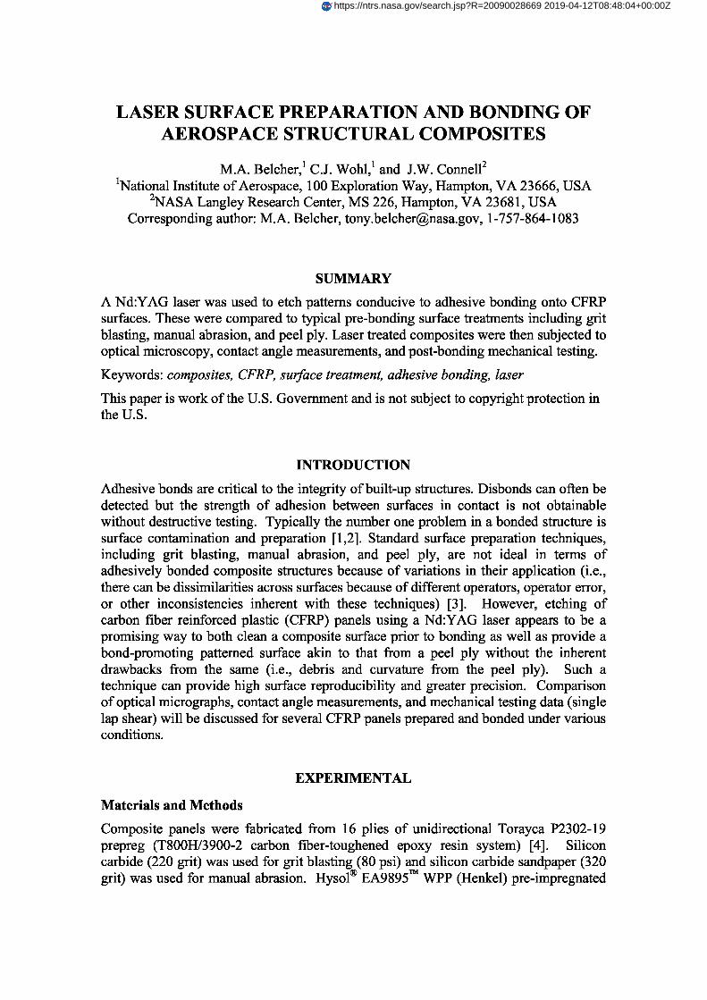
Laser etching of CFRP panels was done using a PhotoMachining, Inc. laser ablationsystem with a Coherent Avia frequency tripled Nd:YAG laser (7-watt output at 355nm). Two different patterns were etched onto CFRP surfaces (see Figure 1). Pattern Awas created to replicate that of a peel ply treated surface while pattern B was a 0/90crosshatch. The following parameters could be adjusted: laser power, frequency, beamwidth, beam spacing, scan speed, and number of passes. For all work the final twoparameters were maintained at 25.4 cm/sec (10 in/sec) and 1, respectively. Beam widthand spacing was kept at the maximum resolution of the laser (25 m [1 mil]). Laserpower was varied among 4.9, 5.6, and 6.3 W while frequency was set to 30, 40, or 60kHz depending on the experiment.
Figure 1. Two patterns used for laser etching: A was designed to replicate the peel plypattern while B is a simple 0/90 crosshatch (drawings not to scale).
Optical Microscopy
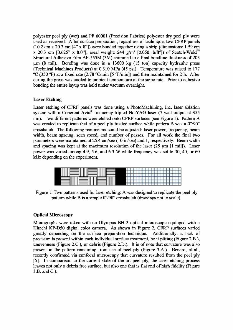
Micrographs were taken with an Olympus BH-2 optical microscope equipped with aHitachi KP-D50 digital color camera. As shown in Figure 2, CFRP surfaces variedgreatly depending on the surface preparation technique. Additionally, a lack ofprecision is present within each individual surface treatment, be it pitting (Figure 2.B.),unevenness (Figure 2.C.), or debris (Figure 2.D.). It is of note that curvature was alsopresent in the pattern remaining from use of peel ply ( Figure 3.A.). Bénard, et al.,recently confirmed via confocal microscopy that curvature resulted from the peel ply[5]. In comparison to the current state of the art peel ply, the laser etching processleaves not only a debris free surface, but also one that is flat and of high fidelity (Figure3.B. and C.).
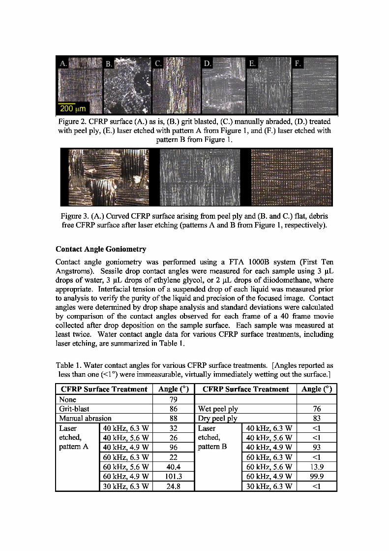
Figure 2. CFRP surface (A.) as is, (B.) grit blasted, (C.) manually abraded, (D.) treatedwith peel ply, (E.) laser etched with pattern A from Figure 1, and (F.) laser etched with
pattern B from Figure 1.
Figure 3. (A.) Curved CFRP surface arising from peel ply and (B. and C.) flat, debrisfree CFRP surface after laser etching (patterns A and B from Figure 1, respectively).
Contact Angle Goniometry
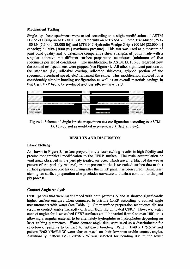
Contact angle go niometry was performed using a FTA 1000B system (First TenAngstroms). Sessile drop contact angles were measured for each sample using 3 µLdrops of water, 3 µL drops of ethylene glycol, or 2 µL drop s of diiodomethane , whereappropriate. Interfacial tension of a suspended drop of each liquid was measured priorto analysis to verify the purity of the liquid and precision of the focused image. Contactangles were determined by drop shape analysis and standard deviations were calculatedby comparison of the contact angles observed for each frame of a 40 frame moviecollected after drop deposition on the sample surface. Each sample was measured atleast twice. Water contact angle data for various CFRP surface treatments, includinglaser etching, are summarized in Table 1.
Table 1. Water contact angles for various CFRP surface treatments. [Angles reported asless than one (<1) were immeasurable, virtually immediately wetting out the surface.]
CFRP Surface Treatment Angle () CFRP Surface Treatment Angle ()None 79Grit-blast 86 Wet peel ply 76Manual abrasion 88 Dry peel ply 83Laseretched,pattern A
40 kHz, 6.3 W 32 Laseretched,pattern B
40 kHz, 6.3 W <140 kHz, 5.6 W 26 40 kHz, 5.6 W <140 kHz, 4.9 W 96 40 kHz, 4.9 W 9360 kHz, 6.3 W 22 60 kHz, 6.3 W <160 kHz, 5.6 W 40.4 60 kHz, 5.6 W 13.960 kHz, 4.9 W 101.3 60 kHz, 4.9 W 99.930 kHz, 6.3 W 24.8 30 kHz, 6.3 W <1
Mechanical Testing
Single lap shear specimens were tested according to a slight modification of ASTMD3165-00 using an MTS 810 Test Frame with an MTS 661.20 Force Transducer ( 25 to100 kN [5,500 to 22,000 lb]) and MTS 647 Hydraulic Wedge Grips (100 kN [22,000 lb]capacity; 21 MPa [3000 psi] maximum pressure). This test was used as a measure ofjoint bond quality and to determine comparative shear strengths of joints made with asingular adhesive but different surface preparation techniques (minimu m of fivespecimens per set of conditions). The modification to ASTM D3165-00 regarded howthe bonded test specimens were gripped (see Figure 4). All other significant portions ofthe standard (i.e., adhesive overlap, adherend thickness, gripped portion of thespecimen, crosshead speed, etc.) remained the same. This modification allowed for aconsiderably simpler bonding configuration as well as an overall materials savings inthat less CFRP had to be produced and less adhesive was used.
Figure 4. Scheme of single lap shear specimen test configuration according to ASTMD3165-00 and as modified in present work (lateral view).
RESULTS AND DISCUSSION
Laser Etching
As shown in Figure 3, surface preparation via laser etching results in high fidelity andprecise topographical modification to the CFRP surface. The resin accumulation orvoid areas observed in the peel ply treated surfaces, which are an artifact of the weavepattern of the peel ply material, are not present in the laser etched surface due to thissurface preparation process occurring after the CFRP panel has been cured. Using laseretching for surface preparation also precludes curvature and debris common to the peelply process.
Contact Angle Analysis
CFRP panels that were laser etched with both patterns A and B showed significantlyhigher surface energies when compared to pristine CFRP according to contact anglemeasurements with water (see Table 1). Other surface preparation techniques did notresult in contact angles markedly different from the untreated CFRP. However, watercontact angles for laser etched CFRP surfaces could be varied from 0 to over 100, thusallowing a singular material to be alternately hydrophilic or hydrophobic depending onlaser etching parameters. Water contact angle data were used as a discriminator forselection of patterns to be used for adhesive bonding. Pattern A/40 kHz/5.6 W andpattern B/60 kHz/5.6 W were chosen based on their low measurable contact angles.Additionally, pattern B/30 kHz/6.3 W was selected for bonding due to the lower
frequency and higher energy etching conditions that were thought to lend themselves todeeper etching.
Surface Energy and Wetting Envelopes
Young’s equation relates the contact angle a liquid makes with a surface () and theliquid’s surface tension (L) to the surface energy of the interrogated material (S).Modifications of Young’s equation separate contributions to the surface energy of amaterial into polar and dispersive components (y p and ,yd respectively). By measuringthe contact angle of multiple liquids on a given surface these parameters can beobtained using extended Fowkes theory (Eq. 1).
0.5
L 051+ COS 8 d 0.5 — YS + YS J d (1)
kn
Eq. 1 can be rewritten to define a domain representing polar-dispersive liquid surfacetension values that would satisfy the criterion of complete wetting (i.e., a contact anglevalue of 0 ¡). This domain is referred to as the wetting envelope. Fluids with surfacetension properties underneath a particular curve (i.e., inside the envelope) will “wet out”the surface spontaneously while those above the curve (i.e., outside the envelope) willnot. For optimum adhesion, an adhesive must thoroughly “wet out” the surface to bebonded. “Wetting out” means the attractive forces between the adhesive and bondingsurface are maximized. For example, a lower surface energy material like water willspontaneously wet out a higher energy surface, such as that of an un-waxed car bonnet(hood).
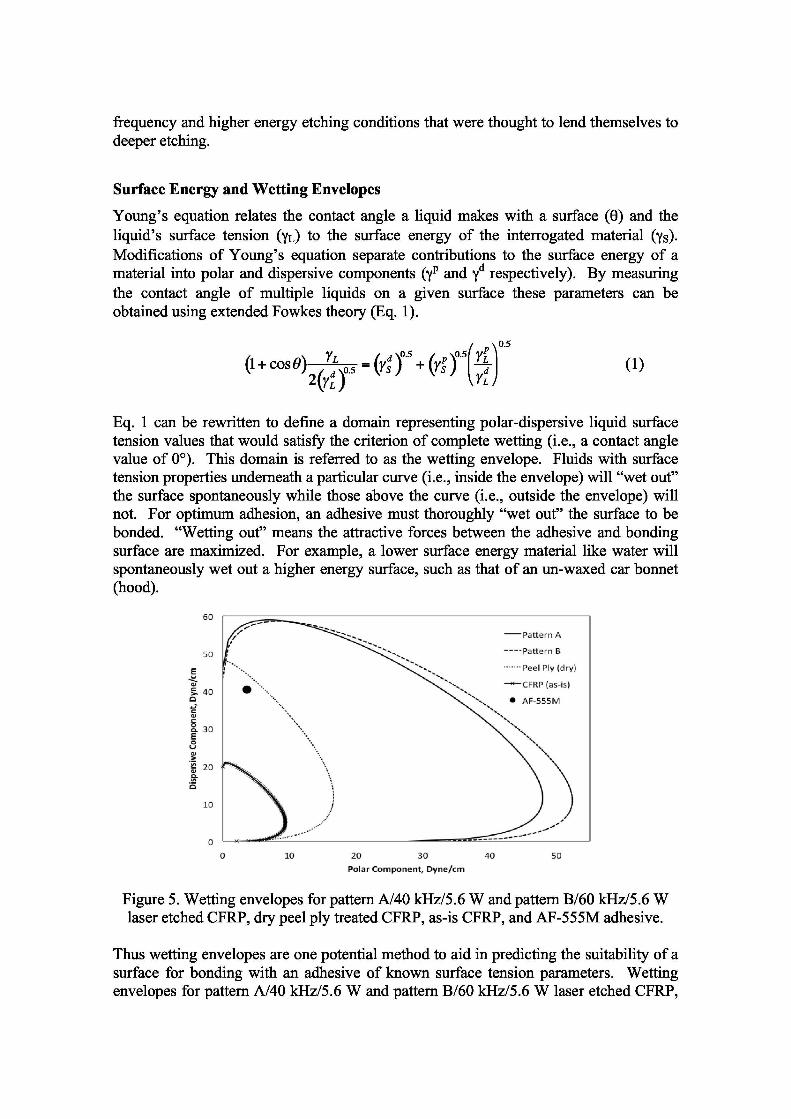
Figure 5. Wetting envelopes for pattern A/40 kHz/5.6 W and pattern B/60 kHz/5.6 Wlaser etched CFRP, dry peel ply treated CFRP, as-is CFRP, and AF-555M adhesive.
Thus wetting envelopes are one potential method to aid in predicting the suitability of asurface for bonding with an adhesive of known surface tension parameters. Wettingenvelopes for pattern A/40 kHz/5.6 W and pattern B/60 kHz/5.6 W laser etched CFRP,
dry peel ply treated CFRP, and as-is CFRP, as well as the location of AF-555Madhesive on this type of plot, are shown in Figure 5. While the wetting envelope for thedry peel ply treated CFRP surface encompasses the adhesive, which suggests theadhesive will wet the peel ply treated surface sufficiently, wetting envelopes for bothlaser etched CFRP surfaces are considerably larger, indicating the adhesive willdefinitely wet out these surfaces. The other discussed surface treatments (i.e., grit-blasting and manual abrasion) did not have wetting envelopes that encompassed theadhesive and these were omitted from Figure 5 for clarity.
Mechanical Testing Data
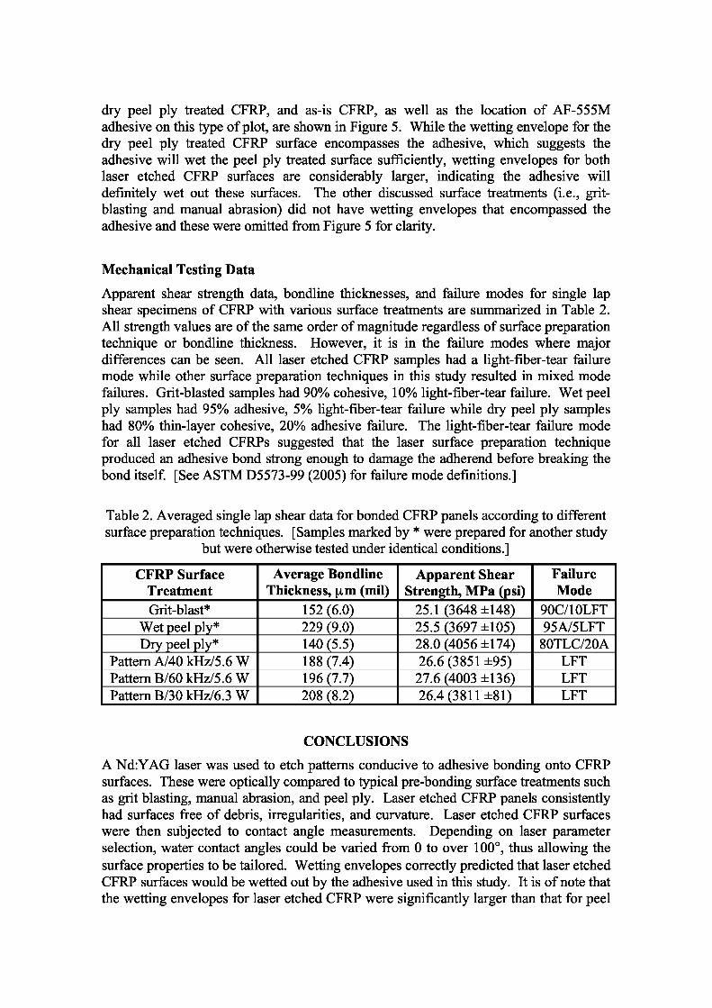
Apparent shear strength data, bondline thicknesses, and failure modes for single lapshear specimens of CFRP with various surface treatments are summarized in Table 2.All strength values are of the same order of magnitude regardless of surface preparationtechnique or bondline thickness. However, it is in the failure modes where majordifferences can be seen. All laser etched CFRP samples had a light-fiber-tear failuremode while other surface preparation techniques in this study resulted in mixed modefailures. Grit-blasted samples had 90% cohesive, 10% light-fiber-tear failure. Wet peelply samples had 95% adhesive, 5% light-fiber-tear failure while dry peel ply sampleshad 80% thin-layer cohesive, 20% adhesive failure. The light-fiber-tear failure modefor all laser etched CFRPs suggested that the laser surface preparation techniqueproduced an adhesive bond strong enough to damage the adherend before breaking thebond itself. [See ASTM D5573-99 (2005) for failure mode definitions.]
Table 2. Averaged single lap shear data for bonded CFRP panels according to differentsurface preparation techniques. [Samples marked by * were prepared for another study
but were otherwise tested under identical conditions.]
CFRP SurfaceTreatment
Average BondlineThickness, m (mil)
Apparent ShearStrength, MPa (psi)
FailureMode
Grit-blast* 152(6.0) 25.1(3648 ±148) 90C/10LFTWet peel ply* 229(9.0) 25.5(3697 ±105) 95A/5LFTDry peel ply* 140(5.5) 28.0(4056 ±174) 80TLC/20A
Pattern A/40 kHz/5.6 W 188(7.4) 26.6(3851 ±95) LFTPattern B/60 kHz/5.6 W 196(7.7) 27.6(4003 ±136) LFTPattern B/30 kHz/6.3 W 208(8.2) 26.4(3811 ±81) LFT
CONCLUSIONS
A Nd:YAG laser was used to etch patterns conducive to adhesive bonding onto CFRPsurfaces. These were optically compared to typical pre-bonding surface treatments suchas grit blasting, manual abrasion, and peel ply. Laser etched CFRP panels consistentlyhad surfaces free of debris, irregularities, and curvature. Laser etched CFRP surfaceswere then subjected to contact angle measurements. Depending on laser parameterselection, water contact angles could be varied from 0 to over 100, thus allowing thesurface properties to be tailored. Wetting envelopes correctly predicted that laser etchedCFRP surfaces would be wetted out by the adhesive used in this study. It is of note thatthe wetting envelopes for laser etched CFRP were significantly larger than that for peel
ply treated CFRP, thus suggesting laser etching to be suitable for perhaps a broaderarray of adhesives. Finally, mechanical testing was done according to ASTM D3165-00. Comparison of this data per surface preparation technique was expected to affordsome correlation to respective contact angle measurements. More specifically, it wasanticipated that higher surface energies (e.g. lower contact angles) would correspond togreater bond strengths . However, apparent shear strength values showed the peel plytreatment and laser etching to be roughly equivalent, with both being slightly better thangrit-blasting. On the other hand, failure modes for laser etched CFRPs stronglysuggested that this laser surface preparation technique produced adhesive bonds robustenough to damage the adherend before breaking the bond.
ACKNOWLEDGEMENTS
The authors thank John W. Hopkins for laser etching; Ricky L. Martin for makingCFRP panels; Sean M. Britton for grit blasting and bonding; Stewart Walker formechanical testing; Dr. Tan-Hung Hou for additional mechanical testing data for grit-blasted and peel ply specimens; Dr. Joseph G. Smith, Jr., for manual abrasion anddiscussions; and Gilda A. Miner for preliminary peel ply work.
REFERENCES
1. G.D. Davis, Surface and Interface Analysis, 1993, 20, pp 368-372.2. M.J. Davis and D. Bond, International Journal ofAdhesion and Adhesives, 1999, 19,pp 91-105.3. J.R.J. Wingfield, International Journal ofAdhesion and Adhesives, 1993, 13, pp 151-156.4. J. Zhang and B.L. Fox, Materials and Manufacturing Processes, 2007, 22, pp 768-772.5. Q. B6nard, M. Fois, M. Grisel, P. Laurens, and F. Joubert, Journal of ThermoplasticComposite Materials, 2009, 22, pp 51-61.