Embed Size (px)
Citation preview

Approved for public release; distribution is unlimited This Research is Sponsored by the NASA Fundamental Aeronautics Program
LASER-INDUCED THERMAL ACOUSTICS THEORY AND EXPECTED EXPERIMENTAL ERRORS WHEN APPLIED TO A SCRAMJET ISOLATOR MODEL
T. F. Middleton*, R. Jeffrey Balla+, R. A. Baurle*
NASA, Langley Research Center, Hampton, Virginia
L. G. Wilson*
Lockheed Martin, NASA, Langley Research Center, Hampton, Virginia
ABSTRACT
A scramjet isolator model test apparatus is being assembled in the Isolator Dynamics Research Lab (IDRL) at the NASA Langley Research Center in Hampton, Virginia. The test apparatus is designed to support multiple measurement techniques for investigating the flow field in a scramjet isolator model. The test section is 1-inch high by 2-inch wide by 24-inch long and simulates a scramjet isolator with an aspect ratio of two. Unheated, dry air at a constant stagnation pressure and temperature is delivered to the isolator test section through a Mach 2.5 planar nozzle. The isolator test section is mechanically back-pressured to contain the resulting shock train within the 24-inch isolator length and supports temperature, static pressure, and high frequency pressure measurements at the wall. Additionally, nonintrusive methods including laser-induced thermal acoustics (LITA), spontaneous Raman scattering, particle image velocimetry, and schlieren imaging are being incorporated to measure off-wall fluid dynamic, thermodynamic, and transport properties of the flow field. Interchangeable glass and metallic sidewalls and optical access appendages permit making multiple measurements simultaneously. The measurements will be used to calibrate computational fluid dynamics turbulence models and characterize the back-pressured flow of a scramjet isolator. This paper describes the test apparatus, including the optical access appendages; the physics of the LITA method; and estimates of LITA measurement uncertainty for measurements of the speed of sound and temperature.
INTRODUCTION
Hypersonic airbreathing vehicles require a high degree of integration between the propulsion system and the vehicle’s airframe. The fore-body surface of the airframe provides a compression surface, which processes the flow passing through the vehicle’s bow shock. Depending on the speed and angle-of-attack of the vehicle, a portion of the processed flow in the shock layer is captured by the inlet and passes into the scramjet isolator. The primary functions of the isolator are to generate and deliver a high-pressure flow to the combustor with minimal aerodynamic losses and to prevent the pressure waves generated in the combustor from propagating upstream into the inlet, potentially causing the inlet to unstart.1-4 In the combustor, fuel is injected, mixed, and reacted with the high pressure flow exiting the isolator. The reacted flow expands through the scramjet nozzle and along the aft body of the vehicle’s airframe to produce thrust. Figure 1 diagrams the components of a typical propulsion-airframe integrated scramjet and illustrates how the back-pressure from the combustion process causes the boundary layer in the isolator to separate and an oblique shock train to form.
* Hypersonic Airbreathing Propulsion Branch, MS-168 + Advanced Sensing & Optical Measurement Branch, MS-493
https://ntrs.nasa.gov/search.jsp?R=20110011132 2019-07-21T19:24:27+00:00Z

In cold-flow experimental configurations, the back-pressure from the combustor is commonly simulated using mechanical means, such as a flow-restricting valve.5 The shock pattern that develops in the isolator varies depending on the ratio of the back-pressure to the inflow static pressure.6 For a high pressure ratio, the boundary layer separates and a pattern of oblique shocks form a shock train within the isolator. The complex flow field has been investigated both numerically and experimentally; however, the vast majority of experimental measurements have been limited to wall pressure measurements, stagnation temperature measurements, Pitot measurements, and a limited amount of nonintrusive measurements such as shadowgraph and schlieren photography.7-11
Figure 1. Components of a typical propulsion-airframe integrated scramjet and features of the associated internal flow.
The NASA Langley Isolator Dynamics Research Lab (IDRL) will support both on-wall and off-wall measurements for investigating the internal flow of a scramjet isolator model.12, 13 The isolator test section and the Mach 2.5 nozzle assembly is approximately 28 inches long and is supplied with unheated, dry air from an ASME Boiler & Pressure Vessel Code “U” stamped settling chamber.
Three sets of interchangeable sidewalls are available to support flow visualization and laser-based measurement techniques as well as temperature, static pressure, and high frequency pressure measurements at the wall. One set is made from fused silica (glass walls) with an 80% optical transmission at 180 nm. A second set is made of 416 stainless steel (metal walls) with a 32 RMS surface finish and machined to accommodate on-wall instrumentation. And the third set is made of 416 stainless steel (slotted walls) and is machined with 0.10-inch wide slots open to optical access appendages to accommodate off-wall laser-based measurements such as LITA. Figure 2 shows the key sections that make up the test apparatus, including the 28-inch long nozzle/isolator section where the interchangeable walls are configured. Note that the assembly is shown horizontal for illustrative purpose. In the lab the assembly is vertical.
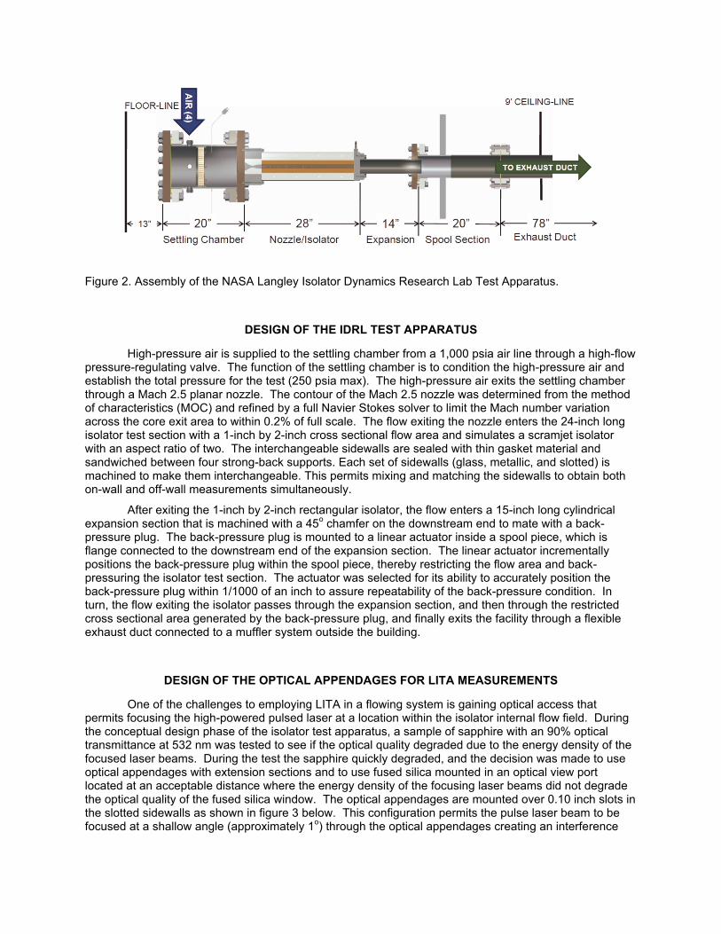
Figure 2. Assembly of the NASA Langley Isolator Dynamics Research Lab Test Apparatus.
DESIGN OF THE IDRL TEST APPARATUS
High-pressure air is supplied to the settling chamber from a 1,000 psia air line through a high-flow pressure-regulating valve. The function of the settling chamber is to condition the high-pressure air and establish the total pressure for the test (250 psia max). The high-pressure air exits the settling chamber through a Mach 2.5 planar nozzle. The contour of the Mach 2.5 nozzle was determined from the method of characteristics (MOC) and refined by a full Navier Stokes solver to limit the Mach number variation across the core exit area to within 0.2% of full scale. The flow exiting the nozzle enters the 24-inch long isolator test section with a 1-inch by 2-inch cross sectional flow area and simulates a scramjet isolator with an aspect ratio of two. The interchangeable sidewalls are sealed with thin gasket material and sandwiched between four strong-back supports. Each set of sidewalls (glass, metallic, and slotted) is machined to make them interchangeable. This permits mixing and matching the sidewalls to obtain both on-wall and off-wall measurements simultaneously.
After exiting the 1-inch by 2-inch rectangular isolator, the flow enters a 15-inch long cylindrical expansion section that is machined with a 45o chamfer on the downstream end to mate with a back-pressure plug. The back-pressure plug is mounted to a linear actuator inside a spool piece, which is flange connected to the downstream end of the expansion section. The linear actuator incrementally positions the back-pressure plug within the spool piece, thereby restricting the flow area and back-pressuring the isolator test section. The actuator was selected for its ability to accurately position the back-pressure plug within 1/1000 of an inch to assure repeatability of the back-pressure condition. In turn, the flow exiting the isolator passes through the expansion section, and then through the restricted cross sectional area generated by the back-pressure plug, and finally exits the facility through a flexible exhaust duct connected to a muffler system outside the building.
DESIGN OF THE OPTICAL APPENDAGES FOR LITA MEASUREMENTS
One of the challenges to employing LITA in a flowing system is gaining optical access that permits focusing the high-powered pulsed laser at a location within the isolator internal flow field. During the conceptual design phase of the isolator test apparatus, a sample of sapphire with an 90% optical transmittance at 532 nm was tested to see if the optical quality degraded due to the energy density of the focused laser beams. During the test the sapphire quickly degraded, and the decision was made to use optical appendages with extension sections and to use fused silica mounted in an optical view port located at an acceptable distance where the energy density of the focusing laser beams did not degrade the optical quality of the fused silica window. The optical appendages are mounted over 0.10 inch slots in the slotted sidewalls as shown in figure 3 below. This configuration permits the pulse laser beam to be focused at a shallow angle (approximately 1o) through the optical appendages creating an interference

grating in the isolator flow and, separately, a continuous wave laser beam to be trained on the same internal measurement location at the phase matching angle.
Figure 3. Plan view and an isometric view of the isolator test section assembled with the optical appendages, extension section, and view ports.
The internal volume of the optical appendages and extension sections is open to the internal flow of the isolator and is pressure matched to the static pressure of the isolator at the axial station of the slot in the isolator slotted wall. Using CFD the effect of the slot and the associated internal volume of the optical appendages and the extension sections was investigated and the results are shown in Figure 4 below. The key feature to note is the location of the incipient shock train is within a single grid spacing of the CFD model for cases run with and without the slotted wall.
Figure 4: CFD calculations of shock train and the wall pressure profiles with and without wall slots.

ISOLATOR CHARACTERIZATION
To characterize the complex flow within the scramjet isolator, the recovery temperature will be measured using a thermocouple probe, the incipient shock location will be determined from wall pressure measurements, and the free-stream static and stagnation pressures will be obtained from Pitot measurements near the nozzle exit. Kulite high frequency transducers will be placed along the top and bottom walls of the isolator to measure the high frequency pressure fluctuations and assess differences between the fluctuations along the top and bottom walls. Schlieren or shadowgraph measurements will be made to qualitatively observe the shock train formed in the isolator. Particle imaging velocimetry (PIV), Raman spectroscopy, and laser-induced thermal acoustics (LITA) measurements will be incorporated to measure the free stream velocity and the velocity profile within the boundary layer as well as temperature, density, and pressure. Table 1 outlines the measurement techniques planned for this experiment.
Sequence
Technique
Parameter
Type
Result
1 Thermocouples
Transducers
Pitot Probe
Kulite
Temperature
Wall Pressure
Stagnation Pressure
High Freq. Pressure
Point
Point
Point
Point, Fluctuation
Recovery Temperature,
Shock Location,
Pitot Flow Velocity,
Unsteady Pressure
2 Schlieren or
Shadowgraph
Flow Visualization Plane Shock Location
3 LITA Speed of Sound
Temperature
Velocity
Local
Local
Local, 3 Component
Full Mapping of Flow Field,
Instantaneous Measurements of
T, u, v, w
4 Raman Trotational, Density, Pressure
Point High Resolution
BL Measurements
5 PIV Velocity Plane Off-wall Velocity
Table 1. Suite of measurement techniques to be employed in the IDRL.
LITA THEORY
LITA is a promising point measurement technique for measuring fluid dynamic, thermodynamic, and transport properties in a flowing system.14-16 Detailed theoretical and experimental descriptions can be found in the literature.17-19 Although measurements of the speed of sound, temperature, and velocity

have been demonstrated, this section only discusses the measurement of the speed of sound and temperature. An experimental schematic is shown in Figure 5, where an Nd:YAG laser (1064 nm, 10 ns pulse width, 800 mJ) is split into two beams and crossed at a shallow angle of approximately 1o. At the focus, optical interference fringes are observed of period
Λ = λpump / 2 sin Θ, (1)
where λpump is the wavelength of the pump laser beam and Θ is one half the crossing angle of the pump laser beams.
For optimum fringe modulation, the lengths of the beam paths must be matched to less than the coherence length of the pump laser. Through electrostriction, two counter propagating sound waves are created with a fixed wavelength near 35 microns. The speed of sound (Vs) is a function of acoustic frequency, temperature, and pressure. The frequency characteristic of the speed of sound is on the order of 16 MHz. Since the laser beam focus is three dimensional, the sound waves form a volume diffraction grating.20 This grating is illuminated using a continuous wave probe laser of typically 5 Watts trained on the diffraction grating at the Bragg phase-matching angle Φ relative to the crossing angle of the pump laser beam. The relation for the Bragg phase matching angle is
sin Φ = (λprobe/ λpump) * sin Θ, (2)
where λprobe is the wavelength of the probe laser beam and λpump is the wavelength of the pump laser beam.
During the LITA measurement a small fraction of the probe laser beam is scattered off the grating at an angle Φ and observed using a 1 GHz detector and digitizer (E-Hart Thermometry). The counter propagating acoustic waves undergo a series of constructive and destructive interferences and decay by acoustic absorption. This modulates the reflectivity of the grating with an exponential decay and thus the intensity of the signal at a frequency equal to twice the frequency of the speed of sound. Since we cannot directly measure our 1o crossing angle to 0.1% accuracy, we effectively measure it with the LITA apparatus using the LITA frequency under known temperature conditions, typically 295K. For the known temperature condition we can calculate the speed of sound and define this as our reference point. Using an oven in which the temperature was measured with a calibrated NIST traceable thermocouple, the speed of sound of the gas in our oven (Voven) is given by the following equation,
Voven = (foven/ fref)*Vref, (3)
where foven and fref are the modulated frequencies at the oven temperature and the reference temperature (295K) respectively, and Vref is the measured speed of sound at the reference temperature.
Figure 5. LITA apparatus for measuring the speed of sound and temperature.

Single laser pulse speed of sound measurements at 296 and 652K are shown in Figure 6. Since the speed of sound increases with increasing temperature, the acoustic waves move faster resulting in a higher modulation frequency. By fitting the data to a damped sinusoidal function, the speed of sound is measured over a 500 ns time period.
Figure 6. Single laser pulse measurement of the speed of sound at 293 and 652K.
To determine errors in our measurement of the speed of sound, experiments were conducted at different oven temperatures. Measurements of the speed of sound in air from 300-650K using a sound frequency range of 10–15 MHz were performed. Figure 7 shows the velocity differences in LITA measurement from the calculated value using the calibrated NIST traceable thermocouple. Based on the average of 100 laser shots, maximum average velocity differences are 0.4%. Typical errors are 0.1%. Error bar uncertainties represent ±2σ and are typically 1%. Note that the speed of sound at 295K in air is 343 m/sec.
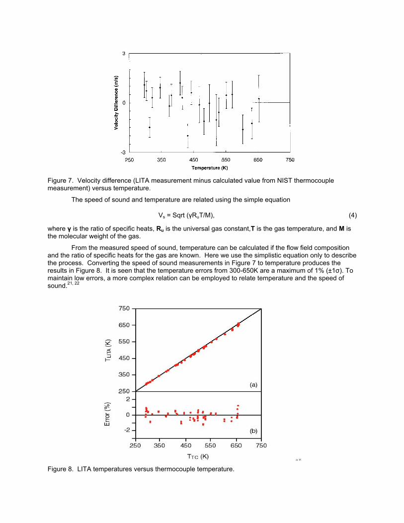
Figure 7. Velocity difference (LITA measurement minus calculated value from NIST thermocouple measurement) versus temperature.
The speed of sound and temperature are related using the simple equation
Vs = Sqrt (γRuT/M), (4)
where γ is the ratio of specific heats, Ru is the universal gas constant,T is the gas temperature, and M is the molecular weight of the gas.
From the measured speed of sound, temperature can be calculated if the flow field composition and the ratio of specific heats for the gas are known. Here we use the simplistic equation only to describe the process. Converting the speed of sound measurements in Figure 7 to temperature produces the results in Figure 8. It is seen that the temperature errors from 300-650K are a maximum of 1% (±1σ). To maintain low errors, a more complex relation can be employed to relate temperature and the speed of sound.21, 22
Figure 8. LITA temperatures versus thermocouple temperature.
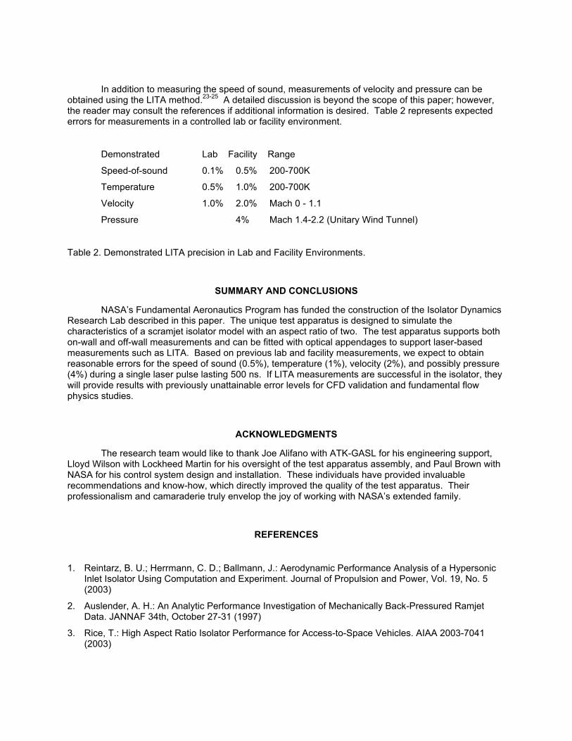
In addition to measuring the speed of sound, measurements of velocity and pressure can be obtained using the LITA method.23-25 A detailed discussion is beyond the scope of this paper; however, the reader may consult the references if additional information is desired. Table 2 represents expected errors for measurements in a controlled lab or facility environment.
Demonstrated Lab Facility Range
Speed-of-sound 0.1% 0.5% 200-700K
Temperature 0.5% 1.0% 200-700K
Velocity 1.0% 2.0% Mach 0 - 1.1
Pressure 4% Mach 1.4-2.2 (Unitary Wind Tunnel)
Table 2. Demonstrated LITA precision in Lab and Facility Environments.
SUMMARY AND CONCLUSIONS
NASA’s Fundamental Aeronautics Program has funded the construction of the Isolator Dynamics Research Lab described in this paper. The unique test apparatus is designed to simulate the characteristics of a scramjet isolator model with an aspect ratio of two. The test apparatus supports both on-wall and off-wall measurements and can be fitted with optical appendages to support laser-based measurements such as LITA. Based on previous lab and facility measurements, we expect to obtain reasonable errors for the speed of sound (0.5%), temperature (1%), velocity (2%), and possibly pressure (4%) during a single laser pulse lasting 500 ns. If LITA measurements are successful in the isolator, they will provide results with previously unattainable error levels for CFD validation and fundamental flow physics studies.
ACKNOWLEDGMENTS
The research team would like to thank Joe Alifano with ATK-GASL for his engineering support, Lloyd Wilson with Lockheed Martin for his oversight of the test apparatus assembly, and Paul Brown with NASA for his control system design and installation. These individuals have provided invaluable recommendations and know-how, which directly improved the quality of the test apparatus. Their professionalism and camaraderie truly envelop the joy of working with NASA’s extended family.
REFERENCES
1. Reintarz, B. U.; Herrmann, C. D.; Ballmann, J.: Aerodynamic Performance Analysis of a Hypersonic Inlet Isolator Using Computation and Experiment. Journal of Propulsion and Power, Vol. 19, No. 5 (2003)
2. Auslender, A. H.: An Analytic Performance Investigation of Mechanically Back-Pressured Ramjet Data. JANNAF 34th, October 27-31 (1997)
3. Rice, T.: High Aspect Ratio Isolator Performance for Access-to-Space Vehicles. AIAA 2003-7041 (2003)

4. Emami, S; Trexler, C. A.; Auslender, A. H.; Weidner, J. P.: Experimental Investigation of Inlet-Combustor Isolators for a Dual-Mode Scramjet at a Mach Number of 4. NASA Technical Paper 3502 (1995)
5. Hass, M; Karanian, A. J.: Small-Scale Supersonic Inlet Test Facility. AIAA 80-1145
6. Lin, P.; Rao, G. V. R.; O’Connor, G. M.: Numerical Analysis of Normal Shock Train in a Constant Area Isolator. AIAA 91-2162 (1991)
7. Waltrup, P. J.; Billig, F. S.: Structure of Shock Waves in Cylindrical Ducts. AIAA Vol. 11, No. 10, October (1973)
8. Sullins, G.: Experimental Results of Shock Trains in Rectangular Ducts. AIAA 92-5103 (1992)
9. Wang, C. P.; Zhang, K. Y.; Yang, J. J.: Analysis of Flows in Scramjet Isolator Combined with Hypersonic Inlet. Presented at AIAA meeting, January 10-13, 2005, Reno Nevada (2005)
10. Carroll, B. F.; Dutton, J. C.: Characteristics of Multiple Shock Wave/Turbulent Boundary-Layer Interactions in Rectangular Ducts. J. Propulsion, Vol. 6, No. 2 (1990)
11. Kumar, A.; Balu, G.; Panneerselvam, S.; Rathakrishnan, E.: Performance of an Isolator Fed with Parallel Flow. Presented at AIAA meeting, July 10-13, 2005, Tucson, Arizona (2005)
12. Middleton, T. F.; Balla, R. Jeffrey; Baurle, R. A.; Wilson, L. G.: Laser Induced Thermal Acoustic Measurements in a Highly Back-Pressured Scramjet Isolator Model: A Research Plan. JANNAF 30th Airbreathing Propulsion May 12-16 (2008)
13. Middleton, T. F.; Balla, R. Jeffrey; Baurle, R. A.; Wilson, L. G.; Humphreys, W. M.: The NASA Langley Isolator Dynamics Research Lab. JANNAF 31th Airbreathing Propulsion December 7-11 (2009)
14. Hart, R. C.; Balla, R. J.; Herring, G. C.: Non-resonant Referenced LITA Thermometry in Air. Applied Optics, 38, 577-584 (1999)
15. Hart, R. C.; Balla, R. J.; Herring, G. C.: Optical Measurement of the Speed-of-Sound in Air Over the Temperature Range 300-650K. The Journal of Acoustical Society of America, 108, 1946-1948 (2000)
16. Hart, R. C.; Balla, R. J.; Herring, G. C.: Simultaneous Velocimetry and Thermometry of Air by Use of Nonresonant Heterodyned Laser-Induced Thermal Acoustics. Applied Optics, 40, 965-968 (2001)
17. E. B. Cummings, I. A. Leyva, and H. G. Hornung, “Laser induced thermal acoustics(LITA) signals from finite beams,” Appl. Opt. 34, 3290–3302 (1995).
18. P. H. Paul, R. L. Farrow, and P. M. Danehy, “Gas-phase thermal-grating contributions to four-wave mixing,” J. Opt. Soc. Am. B 12, 384–392 (1995).
19. E. B. Cummings, “Laser induced thermal acoustics,” Ph.D. dissertation,California Institute of Technology, Pasadena, Calif., 1995.
20. H. J. Eichler, P. Gunter, and D. W. Pohl, Laser-Induced Dynamic Gratings, Springer-Verlag, Berlin, 1986.
21. Hart, R. C.; Balla, R. J.; Herring, G. C.: Non-resonant Referenced LITA Thermometry in Air. Applied Optics, 38, 577-584 (1999).
22. Hart, R. C.; Balla, R. J.; Herring, G. C.: Optical Measurement of the Speed-of-Sound in Air Over the Temperature Range 300-650K. The Journal of Acoustical Society of America, 108, 1946-1948 (2000).
23. Simultaneous velocimetry and thermometry of air by use of nonresonant heterodyned laser-induced thermal acoustics, Applied Optics, 40,965-968(2001).
24. Common-path heterodyne laser-induced thermal acoustics for seedless laser velocimetry, Optics Letters, 27, 710-712(2002).
25. R. C. Hart, G. C. Herring, and R. J. Balla, "Pressure measurement in supersonic air flow by differential absorptive laser-induced thermal acoustics," Opt. Lett. 32, 1689-1691 (2007).