Embed Size (px)
Citation preview

*Corresponding author
Received February 11, 2013
577
Available online at http://scik.org
J. Math. Comput. Sci. 3 (2013), No. 2, 577-593
ISSN: 1927-5307
LASER-INDUCED TEMPERATURE RISE IN A COMPOSITE
SANDWICH STRUCTURE
HONG ZHOU1,*, JOSIAH PICKETT1, AND AURELIA MINUT2
1Department of Applied Mathematics, Naval Postgraduate School, Monterey, CA 93943-5216, USA
2Department of Mathematics, US Naval Academy, Annapolis, MD 21402, USA
Abstract: We investigate the transient temperature rise in a composite sandwich structure induced by a
stationary, dithering, or rotating laser beam. We restrict our study to the composite sandwich structure
with carbon fiber as skin materials and honeycomb as core materials. Our numerical simulations indicate
that the maximum temperature rise behaves as a quadratic function of the reciprocal of the skin thickness
or the effective beam size.
Keywords: dithering or rotating Gaussian laser beam; non-homogeneous heat equation; composite
sandwich structure
2010 AMS Subject Classification: 35K05; 80A20.
1. Introduction
In recent years developing materials, such as materials of composite sandwich
structure, to enhance the damage tolerance of the object has become more and more
important. The goal of this paper is to investigate the maximum temperature rise of a
composite sandwich structure induced by a stationary, rotating and dithering laser beam
and to seek an optimal design of the composite sandwich structure.
The research on the temperature rise induced by a laser beam is not new. In the
past decades many theoretical and numerical studies of temperature profiles induced by

578 HONG ZHOU, JOSIAH PICKETT, AND AURELIA MINUT
laser radiation in solids were conducted (Cline and Anthony, 1977; Lax, 1977 and 1978;
Bertolotti and Sibilia, 1981; Burgener and Reedy, 1982; Calder and Sue, 1982; Moody
and Hendel, 1982; Sanders, 1984; Araya and Gutierrez, 2006; Sistaninia et al., 2009).
Temperature distributions in a two-layer structure by a scanning laser beam were
investigated in (Burgener and Reedy, 1982). Recently, detailed studies of the
temperature rise induced by a rotating or dithering laser beam were given on a
semi-infinite domain (Zhou, 2011a), a solid with finite geometry (Zhou and Tan, 2011;
Tan and Zhou, 2012), a two-layer structure (Zhou, 2011b; Zhou, 2012a) and a
composite with a sandwich structure (Zhou, 2012b).
Composite materials are man-made materials and they are fabricated by
attaching two stiff but thin skins to a thick, lightweight core. The thick core provides the
sandwich-structured composite with high bending stiffness and overall low density. In
(Zhou, 2012b), the performance of a sandwich-structured composite with different
combinations of skin materials and core materials was analyzed. It was found that
carbon fibers are better skin materials than E-glass fibers and composite sandwich
structures with carbon fiber skin and honeycomb core can serve extremely well as
heat shields. However, the scaling behavior of the maximum temperature rise versus
different design parameters was left unexplored in (Zhou, 2012b). In this paper, we
extend our earlier preliminary studies to investigate the effects of design parameters,
including the thickness of the skin materials, the thickness of the core materials and the
beam size, on the maximum temperature rise of the composite. Intuitively, the thicker
the skin is, the smaller the maximum temperature rise will be and it would provide more
heat shields. However, thicker skin will increase the density of the composite and
eventually lose the attractive lightweight property. So there is a compromise between
heat protection and lightweight. We wish to investigate the dependence of the
maximum temperature rise of the structure on the thickness of the skin materials and
provide insight on the design of the composite. Similar argument applies to the
thickness of the core and we need to investigate its effect as well. In this paper we
limit our study to a sandwich-structured composite made of honeycomb core
sandwiched between two thin layers of carbon fibers since this selection of materials

LASER-INDUCED TEMPERATURE RISE 579
has been shown to provide an effective heat shield from our previous studies (Zhou,
2012b).
We organize our paper as follows. In Sections 2-3 we present the modeling and
numerical solutions of the temperature distributions in a three-dimensional composite
sandwich structure induced by a stationary, dithering and rotating laser beam,
respectively. Finally, we draw conclusions in Section 4.
2. MATHEMATICAL FORMULATIONS
We first briefly review a time-dependent mathematical model of a
three-dimensional composite sandwich structure with one core material sandwiched
between two thin layers of other materials. Laser beams hit the top surface of the
sandwich structure. Figure 1 shows a schematic diagram of the composite sandwich
structure. We divide the finite structure into three regions: Region 1 is a thin layer of
thickness 1d in the z direction, which is on a substrate of dissimilar material of
thickness 2d (Region 2), and Region 3 is another thin layer of thickness 3d at the
bottom of the structure. The materials in both Region 1 and Region 3 are the same.
Usually we set 1 3d d= so the top and bottom skin layers share the same thickness.
Figure 1: A schematic diagram of a three-dimensional sandwich-structured
composite.

580 HONG ZHOU, JOSIAH PICKETT, AND AURELIA MINUT
The temperature distribution in the composite sandwich structure can be
modeled by the standard non-homogeneous heat equation (John, 1981). More
specifically, in Region 1 the governing equation is
( )2 2 2
,11 1 1 1,1 2 2 2
,1
, , , ,TT
T
u u u u q x y z tt x y z K
α ∂ ∂ ∂ ∂= α + + + ∂ ∂ ∂ ∂
(1)
where ( )1 , , ,u x y z t denotes the temperature rise at position ( ), ,x y z and time t , ,1Tα
is the thermal diffusivity of the material in Region 1, ,1TK is the thermal conductivity,
and ( ), , ,q x y z t is the energy distribution of the incident laser beam. In the simulations
presented here we model the distribution of a dithering or rotating Gaussian beam as
( ) ( ) ( )0, , , , , .q x y z t f x y t z z= δ − (2)
Here ( ), ,f x y t has the expression
( ) ( )( ) ( )( )
( )
( )
2 2
02 2
0 0
0 0
, , exp ,2 2
2cos , ,2
2sin , ,2
c c
xc
yc
x x t y y tIf x y td d
Ltx t x a xT
Lty t y b yT
− + − = −
π
π= + =
π= + =
(3)
where ( ) ( )( )0, ,c cx t y t z describes the position of the dithering or rotating Gaussian
beam, ( )0 0 0, ,x y z gives the initial position of the moving laser beam, 0I is the
intensity of the laser beam, d is the effective radius of the laser beam, and ( )0z zδ −
is the Dirac delta function. Equation (3) represents a rotating laser beam when a b=
and a dithering beam when either a or b is zero. When 0a b= = , equation (3)
simply represents a non-moving stationary Gaussian beam.
In Region 2, where the material has the thermal diffusivity ,2Tα and thermal
conductivity ,2TK , the governing equation for the temperature rise ( )2 , , ,u x y z t is
given by

LASER-INDUCED TEMPERATURE RISE 581
2 2 22 2 2 2
,2 2 2 2 .Tu u u ut x y z
∂ ∂ ∂ ∂= α + + ∂ ∂ ∂ ∂
(4)
Similarly, in Region 3 the equation for the temperature rise ( )3 , , ,u x y z t is
2 2 23 3 3 3
,3 2 2 2 .Tu u u ut x y z
∂ ∂ ∂ ∂= α + + ∂ ∂ ∂ ∂
(5)
At the interfaces between different regions/materials, we impose the physical condition
that the energy is conserved for the heat flow across the interfaces:
1 2,1 ,2
32,2 ,3
T T
T T
u uK K at the interface between Regions 1 and 2z z
uuK K at the interface between Regions 2 and 3z z
∂ ∂=
∂ ∂∂∂
=∂ ∂
(4)
The initial condition for the temperature rises ( ) ( ) ( )1 2 3, , , , , , , , , , ,u x y z t u x y z t u x y z t
is zero to reflect the fact that initially, the composite sandwich structure shares the same
temperature as the ambient. The boundary conditions at the air/material interface
require that the sandwich structure is insulated at all edges. The boundary conditions
take the assumption that no energy leaks into the ambient at the air/material interface.
This is fairly a good approximation for most materials under consideration because heat
flow by conduction through the material is usually much larger than heat loss by
radiation or convection at the air/material interface.
For the top (Region 1) and bottom (Region 3) layers of the composite sandwich
structure, the materials are chosen to be carbon fibers. Carbon fibers are well-known
for their high flexibility, high tensile strength, low weight, high temperature tolerance
and low thermal expansion. They are widely used in aerospace, civil engineering,
military, and automobile. For Region 2 we select lightweight, flame resistant Nomex
honeycomb as the core material. The corresponding thermal properties of carbon fibers
and Nomex honeycomb are given in Table 1 (Wang et al. 2007; Silva et al. 2005).
It is worthwhile to note that the skin materials have much larger thermal
conductivity than the core materials.

582 HONG ZHOU, JOSIAH PICKETT, AND AURELIA MINUT
Table 1: Thermal properties for carbon fibers and Nomex honeycomb
Materials
Heat Capacity
(or Specific
Heat) pC
(unit: J/(kg*K))
Density ρ
(unit: 3/Kg m )
Thermal
Conductivity
TK
(unit:
W/(m*K))
Thermal Diffusivity
Tα =T
p
KCρ ⋅
(unit: 2 /m s )
Carbon
fibers
676
1760
84
57.0602 10−×
Honeycomb 1172 ~ 1340 1100 0.175 7 71.1872 10 1.3574 10− −× ×
3. NUMERICAL RESULTS
In this section we investigate the effects of different design parameters on the
maximum temperature rise of a sandwich-structured composite. We apply the
commercial software COMSOL to solve the partial differential equations (1)-(4) with
the prescribed initial and boundary conditions. COMSOL is a multi-physics
commercial software based on finite element methods which can be used to solve our
model equations efficiently.
We first construct a sandwich structure where the core has thickness 2d (mm)
and cross section dimension 304.8 304.8mm mm× and the top and bottom skins are
with thickness 1 3d d= (mm). In our study we will fix 2d and vary 1d and then we
will fix 1d and vary 2d .
We start with a stationary Gaussian beam applied on the top surface of the sandwich
structure where 0 500 , 0.0025 , 0, 0.3048x yI W d m a b L L m= = = = = = in (3). In
Figure 2(a) we take a snapshot of the temperature rise distribution of the composite
structure after the laser beam is shone for 6 seconds on the top surface whereas in

LASER-INDUCED TEMPERATURE RISE 583
Figure 2(b) we show the temperature rise in a vertical slice across the center of the top
surface.
(a) (b)
Figure 2: The temperature rise of a sandwich structure induced by a stationary
Gaussian beam. (a) a 3-D view; (b) a vertical slice through the center of the top
surface.
From Figure 2 we see that the maximum temperature (around 3358K) occurs at the
center of the top surface which is exactly the spot where the laser beam hits the
structure. In Figure 3 we plot the transient temperature rise at the center of the top
surface. As time goes by, the spot gets hotter and hotter. Here the thickness of the core
is fixed as 2 6d mm= and the skin thickness is chosen as 1 3 0.5d d= = mm.
Figure 3: The transient temperature rise of a sandwich structure at the center of
the top surface.

584 HONG ZHOU, JOSIAH PICKETT, AND AURELIA MINUT
Now we vary the thickness of the skin from 0mm (no skin) to 1mm and compute
the maximum temperature rise in the composite structure. The maximum temperature
rise versus the thickness of the skin is plotted in Figure 4(a).
(a) (b)
Figure 4: (a) The maximum temperature rise of a sandwich structure as a
function of the skin thickness. (b) The data in Figure 4(a) fitted by two different
least squares functions.
Note that even with a thin layer of skin on the top and bottom of the core, the
maximum temperature rise can be reduced significantly in comparison with the case
where there is no skin at all. So even with a thin layer of skin one gains big protection.
In Figure 4(b) we fit the data in Figure 4(a) by two different sets of least squares fitting
functions. The dashed curve corresponds to the fitting function
max1
1.001 1233.3fittedTd
= + whereas the solid curve is described by
max 21 1
0.000047 1.5 486.0fittedTd d
−= + + . The maximum temperature rise is fitted better by
the second fitting function which is a quadratic function of the reciprocal of the skin
thickness.
A practical interpretation of Figure 4 can be as follows. If we want to build an
object with sandwich structured composite materials which can survive laser attacks

LASER-INDUCED TEMPERATURE RISE 585
(with power 500W) for six seconds with a maximum temperature rise less than, say,
4000K, then the skin thickness should be greater than 0.4mm.
Another possible way to enhance damage tolerance is to increase the core thickness
while fixing the skin thickness. Intuitively, increasing core thickness will enlarge the
bulk volume of the materials and therefore is expected to reduce the maximum
temperature rise at a fixed time. We carried out some preliminary simulations and our
results indicate that changing the core thickness is not significant in reducing the
maximum temperature rise.
Now we would like to see how the beam size affects the maximum temperature rise
of the composite. We fix the composite structure so that the top and bottom skin layers
have thickness 1 3 0.5d d= = mm and the middle core has thickness 2 6d = mm while
varying the effective beam radius d from 1mm to 5mm. Figure 5(a) depicts the
maximum temperature rise as a function of the effective beam radius whereas Figure
5(b) shows two sets of least squares fittings with the data in Figure 5(a).
(a) (b)
Figure 5: (a) The maximum temperature rise of a sandwich structure versus the
effective beam radius of a stationary Gaussian beam. (b) The data in Figure 6(a)
fitted by two different least squares functions.

586 HONG ZHOU, JOSIAH PICKETT, AND AURELIA MINUT
More specifically, in Figure 5(b) the dotted curve is fitted by the function
max4.1 1637.3fittedTd
= + while the solid curve is fitted by the function
max 2
0.0064 9.5590 646.1341fittedTd d
−= + + . It appears that the solid curve fits the data
better than the dotted curve. Figure 5 shows that the maximum temperature rise
decreases when the beam size increases. This is expected since the beam becomes less
focused when its size increases.
Next we study the temperature rise induced by a dithering laser beam. In formula (3)
we choose 0 500 , 0.0025 , 0, 0.05 , 0.3048 , 1x yI W d m a b m L L m T s= = = = = = = . In
Figure 6 we give a snapshot of the temperature rise at final time=6s of the top surface
(left panel) and the vertical slice passing through the center of the top surface (right
panel). Due to the dithering nature of the beam, the maximum temperature rise occurs at
different spots at different times. The maximum temperature rise induced by a dithering
beam is dropped significantly to 862K compared with the stationary beam case where
the maximum temperature rise is around 3358K.
(a) (b)
Figure 6: The maximum temperature rise of a sandwich structure induced by a
dithering laser beam. Left panel: top surface; right panel: a vertical slice.
We also follow the transient temperature rise at a fixed point (the center of the
top surface). The result is shown in Figure 7. Due to the fact that the beam moves back

LASER-INDUCED TEMPERATURE RISE 587
and forth along a line and passes through the center periodically, the temperature rise at
a fixed point oscillates and the envelope of the amplitude increases with time.
Figure 7: The transient dithering-laser-beam-induced temperature rise of a
sandwich structure at the center of the top surface.
For a dithering laser beam, we will investigate the effect of the skin thickness as
well as the effect of the beam size on the maximum temperature rise. From the previous
study of the stationary beam, the maximum temperature rise is not very sensitive to the
core thickness and therefore will not be studied any more. In Figure 8(a) we show the
maximum temperature rise dependence on the thickness of the skin layer while in
Figure 8(b) we fit the data with two different least squares functions. The dotted curve
corresponds to the fitted function max1
0.2210 401.7029fittedTd
= + whereas the solid
curve is described by max 21 1
0.000016 0.395 143.20fittedTd d
−= + + . As expected, a
combination of sandwich structure and dithering beam leads to a big reduction in the
maximum temperature rise.

588 HONG ZHOU, JOSIAH PICKETT, AND AURELIA MINUT
(a) (b)
Figure 8: (a) The dithering-beam-induced maximum temperature rise of a
sandwich structure as a function of the skin thickness. (b) The data fitted by two
different least squares functions.
In Figure 9(a) we plot the maximum temperature rise as a function of the
effective laser beam radius. As the beam size increases, the maximum temperature rise
decreases. We fit the data in Figure 9(a) by two different functions in Figure 9(b). Here
the dashed curve is described by a linear function of the reciprocal of the beam radius
max0.6795 561.4320fittedT
d= + and the solid curve is given by a quadratic function of the
reciprocal of the beam radius max 2
0.0018 2.2564 275.2048fittedTd d
−= + + . Clearly, the
maximum temperature rise behaves more like a quadratic function of the reciprocal of
the beam size.
(a) (b)
Figure 9: (a) The maximum temperature rise of a sandwich structure versus the
effective beam radius of a dithering Gaussian beam. (b) The data fitted by two
different least squares functions.

LASER-INDUCED TEMPERATURE RISE 589
Finally we move to the temperature rise induced by a rotating laser beam. First
in Figure 10(a) we take a snapshot of the temperature rise induced by a rotating laser
beam with 0 500 , 0.0025 , 0.05 , 0.3048x yI W d m a b m L L m= = = = = = in expression
(3).
(a) (b)
Figure 10: The maximum temperature rise of a sandwich structure induced by a
rotating laser beam. Left panel: top surface; right panel: a vertical slice.
Figure 10(a) indicates that the maximum temperature rise drops further to about
323K. Figure 10(b) shows the temperature rise on a vertical slice.
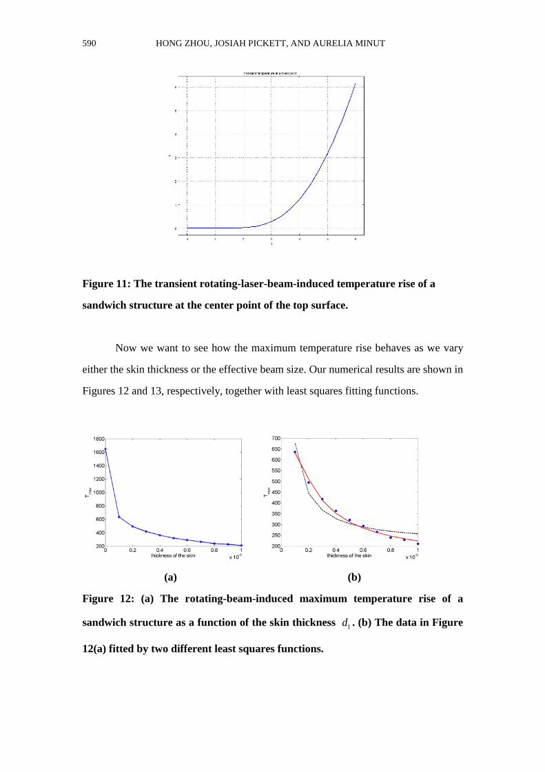
In Figure 11 we plot the transient temperature rise at the center point of the top
surface. Here the temperature rise increases monotonically as a function of time even
though the magnitude of the temperature rise is very small. The increasing nature of the
temperature is due to the insulating boundary condition.
590 HONG ZHOU, JOSIAH PICKETT, AND AURELIA MINUT
Figure 11: The transient rotating-laser-beam-induced temperature rise of a
sandwich structure at the center point of the top surface.
Now we want to see how the maximum temperature rise behaves as we vary
either the skin thickness or the effective beam size. Our numerical results are shown in
Figures 12 and 13, respectively, together with least squares fitting functions.
(a) (b)
Figure 12: (a) The rotating-beam-induced maximum temperature rise of a
sandwich structure as a function of the skin thickness 1d . (b) The data in Figure
12(a) fitted by two different least squares functions.

LASER-INDUCED TEMPERATURE RISE 591
In Figure 12, the dashed curve is given by max1
0.0469 210.4757fittedTd
= +
whereas the solid curve is max 21 1
0.000005 0.104 125.98fittedTd d
−= + + .
Figure 12 and Figure 13 again demonstrate that the maximum temperature rise can
be described by a quadratic function of the reciprocal of the skin thickness or the beam
size where the coefficients in the quadratic form are different for each case.
(a) (b)
Figure 13: (a) The maximum temperature rise of a sandwich structure versus the
effective beam radius of a rotating Gaussian beam d . (2) The data in Figure 13(a)
fitted by two different least squares functions. The dashed curve is described by
max0.35 173.65fittedT
d= + and the solid curve is max 2
0.000527 0.7998 92.01fittedTd d
−= + + .
4. CONCLUDING REMARKS
We have shown numerically how the maximum temperature rise induced by a
laser beam for a composite sandwich structure scales as a function of the thickness of
the skin layer or the effective beam size. Our study includes three kinds of laser
beams: a stationary Gaussian beam, a dithering Gaussian beam or a rotating Gaussian
beam. All the cases share a universal rule: the maximum temperature rise behaves as a
quadratic function of the reciprocal of the skin thickness or the effective beam size.
Validation of our predictions with the experimental data will be pursued in the future.

592 HONG ZHOU, JOSIAH PICKETT, AND AURELIA MINUT
ACKNOWLEDGMENT
We would like to thank the Office of Naval Research (ONR) for supporting
this work.
REFERENCES
[1] G. Araya, G. and G. Gutierre, Analytical solution for a transient, three-dimensional temperature
distribution due to a moving laser beam, Int. J. Heat and Mass Transfer, 49 (2006), 4124-4131.
[2] N. Asmar, Partial Differential Equations with Fourier Series and Boundary Value Problems, 2nd
edition (2004), Prentice Hall, Upper Saddle River, New Jersey.
[3] M. Bertolotti and C. Sibilia, Depth and velocity of the laser-melted front from an analytical solution
of the heat conduction equation, IEEE J. Quantum Electron., QE-17 (1981), 1980-1989.
[4] R. Burden, R. and J. Faires, Numerical Analysis, 8th edition (2005), Brooks/Cole, Boston.
[5] M. Burgener and R. Reedy, Temperature distributions produced in a two-layer structure by a
scanning cw laser or electron beam, Journal of Applied Physics, 53 (1982), 4357-4363.
[6] J. Calder and R. Sue, Modeling of cw laser annealing of multilayer structures, Journal of Applied
Physics, 53 (1982), 7545-7550.
[7] H. Cline and T. Anthony, Heat treating and melting material with a scanning laser or electron beam,
Journal of Applied Physics, 48 (1977), 3895-3900.
[8] F. John, .Partial Differential Equations, Springer, New York, 1981.
[9] M..Lax, Temperature rise induced by a laser beam, Journal of Applied Physics, 48(1977), 3919-3924.
[10] M. Lax,Temperature rise induced by a laser beam II. The nonlinear case, Applied Physics Letter, 33
(1978), 786-788.
[11] J. Moody and R. Hendel, Temperature profiles induced by a scanning cw laser beam, Journal of
Applied Physics, 53 (1982), 4364-4371.
[12] D. Sanders, Temperature distributions produced by scanning Gaussian laser beams, Applied Optics,
23(1984), 30-35.
[13] S. Silva, M. Sabino, E. Fernandes, V. Correlo, L. Boesel, and R. Reis, Cork: properties, capabilities
and applications, International Materials Review, 50(6) (2005), 345-365.
[14] Me. Sistaninia, Ma. Sistaninia, and H. Moeanodini, Laser forming of plates using rotating and
dithering beams, Computational Materials Science, 45 (2009), 480-488.

LASER-INDUCED TEMPERATURE RISE 593
[15] T. Tan, Temperature rise induced by a rotating/dithering laser beam on a finite solid, Naval
Postgraduate School, Master Thesis, 2010.
[16] T. Tan, T. and H. Zhou, Numerical solution for a transient temperature distribution on a finite
domain due to a dithering or rotating laser beam, International Journal of Operations Research and
Information Systems, in press.
[17] Z. Wang, D. Tang, and W. Zhang, Simultaneous measurements of the thermal conductivity, thermal
capacity and thermal diffusivity of an individual carbon fibre, Journal of Physics D: Applied Physics, 40
(2007), 4686-4690.
[18] H. Zhou, Temperature rise induced by a rotating or dithering laser beam, Advanced Studies in
Theoretical Physics, 5(10) (2011a), 443-468.
[19] H. Zhou, Transient temperature distributions produced in a two-layer finite structure by a dithering
or rotating laser beam, Fourteenth Annual Directed Energy Symposium Proceedings (2011b),
1416-1431.
[20] H. Zhou, H. and T. Tan, Transient temperature distribution on a finite domain induced by a dithering
or rotating laser beam, 2011 Directed Energy Systems Symposium Proceedings (2011), 83-105.
[21] H. Zhou, Temperature rise in a two-layer structure induced by a rotating or dithering laser beam,
Journal of Mathematical and Computational Science, 2(2)(2012a), 339-359.
[22] H. Zhou, Transient temperature rises in a sandwich-structured composite induced by a dithering or
rotating laser beam, IOSR Journal of Engineering, 2(2)(2012b), 234-246.