Embed Size (px)
Citation preview
Laser Induced Rectangular Microstructures for Surface of Cavitation Erosion Resistance
Haifeng Yang1,2, Bo Sun1, Hao Liu1*, Yanqing Wang3*, Kun Liu1, Xianhua Tian1
1School of mechatronic Engineering, China University of Mining & Technology, Xuzhou, 221116, China
E-mail:[email protected] 2Jiangsu Key Laboratory of Mine Mechanical and Electrical Equipment, China University of
Mining & Technology, Xuzhou, 221116, China 3 School of material science and Engineering, Xuzhou Institute of Technology, Xuzhou, 221116,
China
In the design of hydraulic machines, the application of surface treatments is essential to improve the cavitation erosion resistance of components. In this paper, the cavitation erosion behavior of rectangular microstructure surfaces was studied. Before cavitation erosion experiments, the surface of 1060 high purity aluminum plate was processed by laser microfabrication method to generate rectangular microstructures with special groove depth, groove width and different periods. The cavitation tests were carried out using a commercially available ultrasonic vibratory apparatus. Before and after the cavitation erosion experiments, specimens with rectangular microstructures were measured for calculating the average cavitation erosion losses with analytical balances, analyzed for exploring cavitation erosion mechanisms using numerical simulation, scanning electron microscopy and optical microscopy. The results showed that rectangular microstructure surfaces, compared to the smooth surfaces, have better cavitation erosion performance, and its period, as an important parameter of the microstructure configuration, was a factor affecting cavitation erosion resistance. The cavitation erosion resistance mechanisms of rectangular microstructure surfaces were lower vapor volume fraction and smaller pressure fluctuation, which will not lead to the contraction and collapse of the bubbles.
Keywords: cavitation erosion resistance, ultrasonic cavitation, laser, rectangular microstructure, numerical simulation
1. Introduction Cavitation erosion was an important reason for
surface damage of hydraulic systems, e.g. ship propellers, pump impellers, hydro-turbines, and offshore/mining machineries. When bubbles collapse in the vicinity of a solid surface [1-2], collapsing cavities generate micro-jets and shock waves which cause the material loss of the specimen [3]. A wide range of studies concerning bubble dynamics and material processing [4-5], have been proposed to reduce cavitation wear, such as laser processing, coating technique, expensive materials and ion implantation.
Recent years, the cavitation erosion behaviors of the various materials have been extensively studied by the researchers [6-7]. The results indicated that cavitation erosion resistance was greatly affected by the properties and microstructure of materials. It is very important to develop engineering materials with high cavitation erosion resistance. B.S. Mann et al. improved the cavitation erosion behavior of Ti-6Al-4V alloy using a duplex treatment of twin wire arc spraying and high power diode laser [8]. Haibin Li showed the best cavitation erosion behavior of CP-Ti sample after gas nitriding process [9]. L.
Zhang proved the effects of laser shock processing on electrochemical corrosion resistance of weldments. They found that laser shock processing can induce compressive residual stresses, decrease surface roughness, refine grains and generate the slip, and thus improve the erosion and corrosion resistance of ANSI 304 stainless steel weldments [10]. Surface topography is an important factor affecting surface cavitation. It is generally believed that smooth surfaces had good performances of cavitation erosion resistance [11]. Ahmed and others [12] pointed out that the rough locations of the specimen surface were conducive to the formation of cavitation pits. However, some investigators [13] thought that surface topography (pitting, holes and cracks) were beneficial for forming water cushion and had good effects on reducing cavitation erosion. Y.J. Li showed that surface topography manufactured by formed cutter had remarkable influences on the incubation of cavitation erosion [14]. He introduced that the cavities move into or keep transporting next to the solid surface and the raised pressure caused by the surface topography acts on the cavities and drives them to collapse, and finally induce the cavitation erosion. The dimension, shape and distribution of the topography will affect the
DOI: 10.2961/jlmn.2017.02.0017
JLMN-Journal of Laser Micro/Nanoengineering Vol. 12, No. 2, 2017
146
erosion degree greatly [14]. Feng Lian investigated the cavitation erosion resistance of laser-modified textures on Ti6Al4V alloy surface. She found that the cavitation erosion resistances of all the textured surfaces were better than that of smooth surface and dot texture surface had the best properties compared to the line texture and grid texture surfaces [15, 16]. However, J. Zou investigated the cavitation erosion properties of different surface topography of AlSi10Mg and indicated that the laser textured surface had higher cavitation erosion rate than polished, turned and ground surfaces [17]. Therefore, reasonable design of surface topography can alleviate the formation, transportation, growth and collapse of the cavities, and finally reduce surface cavitation erosion. Surface topography involves a large number of complex structure and many parameters, in which rectangular microstructure is simple and it has less characteristic parameters. For a microstructure type, many parameters will affect the cavitation erosion process simultaneously and increase the complexity. Compared with other type of complex microstructures, it is easy to investigate the influence of each characteristic parameter of rectangular microstructure on the cavitation erosion performance. Therefore, this paper only uses the rectangular microstructures to explore its cavitation erosion behavior.
There are many methods for fabricating surface microstructures, for example mechanical processing, photolithography, electrochemical deposition, anodic oxidation. Compared with these methods, laser fabrication technique has many advantages, such as adaptability for extensive materials, operability for many kinds of microstructures, high efficiency and low cost [18-20]. However, there was very little founds regarding the cavitation erosion behavior of laser induced microstructures surface. Therefore, the aim of the paper was to investigate the cavitation erosion behavior of the laser induced microstructures material surface and to explore the cavitation erosion mechanisms. 2. Experimental details 2.1. Specimen preparation
Firstly, the flow fields on the microstructure surface were simulated by FLUENT software, and the parameters of the rectangular microstructure were designed according to the simulation results. Then, the rectangular microstructures were fabricated on the surface of 1060 high purity aluminum plate by laser microfabrication platform. Before and after the cavitation experiments, specimens were ultrasonic cleaned in acetone for 5min, dried in the oven at 105℃ for 10min and weigh three times to calculate the average value with 0.1mg analytical balances (Model: BSA224S-CW). In addition, before and after the cavitation erosion experiments, the rectangular microstructure surface was analyzed by SEM (Model: QuantaTM 250) and optical microscopy. 2.2 Fabrication of rectangular microstructure surface
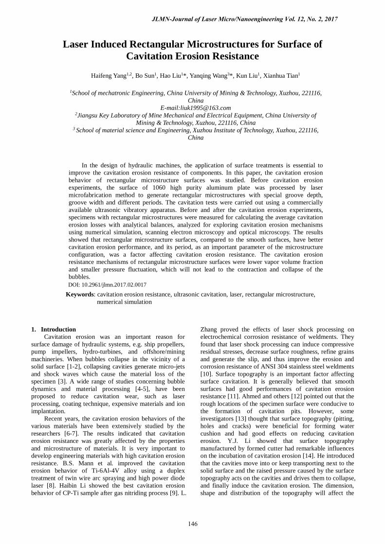
Rectangular microstructures on the surface of 1060 high purity aluminum plate are fabricated by laser microfabrication platform. Figure 1 shows the schematic diagram of laser microfabrication platform. An ultraviolet nanosecond laser (Model: DSH-355-10) was served as the exposure source with 355 nm wavelength, 25ns pulse width, and 6868Hz pulse frequency. The parameters for
laser processing were laser power of 520mW, Gaussian spot diameter of 15μm and traversing speed of 5.08 mm/s. The scanning path of laser focus can be controlled by the MarkingMate software in the computer.
Figure1 Schematic diagram of laser microfabrication platform
2.3 Cavitation erosion tests
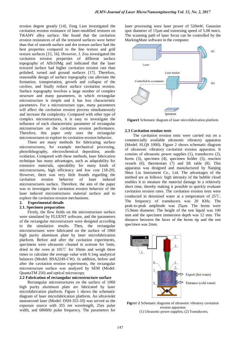
The cavitation erosion tests were carried out on a commercially available ultrasonic vibratory apparatus (Model: SLQS 1000). Figure 2 shows schematic diagram of ultrasonic vibratory cavitation erosion apparatus. It consists of ultrasonic power supplies (1), transducers (2), horns (3), specimen (4), specimen holder (5), reaction vessels (6), thermostats (7) and lift table (8). This apparatus was designed and manufactured by Nanjing Shun Liu Instrument Co., Ltd. The advantages of the method are as follows: high intensity of the bubble cloud enables it to measure the material damage in a relatively short time, thereby making it possible to quickly evaluate cavitation erosion rates. The cavitation erosion tests were conducted in deionized water at a temperature of 25℃. The frequency of transducers was 20 KHz. The peak-to-peak amplitude was 25μm. The horns were 15.9mm diameter. The height of the test liquid was 100 mm and the specimen immersion depth was 12 mm. The distance between the faces of the horns tip and the test specimen was 2mm.
Figure 2 Schematic diagrams of ultrasonic vibratory cavitation
erosion apparatus (1) Ultrasonic power supplies; (2) Transducers;
JLMN-Journal of Laser Micro/Nanoengineering Vol. 12, No. 2, 2017
147
(3) Horns; (4) Specimen; (5) Specimen holder; (6) Reaction vessels; (7) Thermostats; (8) Lift table.
2.4 Numerical simulation of ultrasonic cavitation
The ultrasonic cavitation field was investigated by numerical simulation method using FLUENT software. Unsteady calculation was used and the acceleration was set to 9.81m/s2. Realizable k-ε model was adopted for turbulence item and standard wall function was selected for near wall. There were both liquid and vapor in the simulation region, which belongs to the two-phase flow. There were three different multiphase flow models in the FLUENT software [21], such as VOF, Eularian and Mixture. Compared to the other two kind of model, Mixture was commonly used to bubble flow, sedimentation and cyclone separator. Taking into account the bubble flow distribution of ultrasonic cavitation flow field in our simulation, the Mixture model was selected in the multiphase flow, in which the liquid was the main item and the vapor was the second term. There were three kinds of cavitation models in FLUENT software [21], such as Singhal model, Zwart-Gerber-Belamri model and Schnerr & Sauer model. Schnerr &Sauer model had better stability and robustness and it was not very sensitive to initial conditions. Therefore, the Schnerr & Sauer model was selected for the cavitation model, where the saturated vapor pressure of water was 3540 Pa, and the surface tension coefficient of gas - liquid was 0.0717N/m. The pressure at the pressure outlet was set to 0 MPa, and the turbulence intensity and turbulence viscosity were set to 0.5 and 5, respectively. 3 Results and Discussions 3.1 Cavitation erosion resistance of rectangular microstructure surfaces
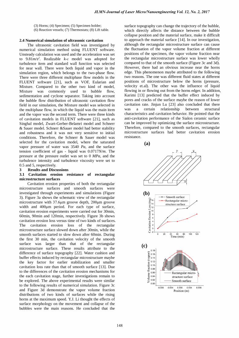
Cavitation erosion properties of both the rectangular microstructure surfaces and smooth surfaces were investigated through experiments and simulations (Figure 3). Figure 3a shows the schematic view of the rectangular microstructure with 37.6μm groove depth, 200μm groove width and 400μm period. For each type of surface, cavitation erosion experiments were carried out for 30min, 60min, 90min and 120min, respectively. Figure 3b shows cavitation erosion loss versus time of two kinds of surfaces. The cavitation erosion loss of the rectangular microstructure surface slowed down after 30min, while the smooth surfaces started to slow down after 60min. During the first 30 min, the cavitation velocity of the smooth surface was larger than that of the rectangular microstructure surface. These results attribute to the difference of surface topography [22]. Water cushion and buffer effects induced by rectangular microstructure maybe the key factor for earlier stabilization and smaller cavitation loss rate than that of smooth surface [13]. Due to the differences of the cavitation erosion mechanisms for the each cavitation stage, further investigations remain to be explored. The above experimental results were similar to the following results of numerical simulation. Figure 3c and Figure 3d demonstrate the vapor volume fraction distributions of two kinds of surfaces while the rising horns at the maximum speed. Y.J. Li thought the effects of surface morphology on the movement and collapse of the bubbles were the main reasons. He concluded that the
surface topography can change the trajectory of the bubble, which directly affects the distance between the bubble collapse position and the material surface, make it difficult to approach the material surface [14]. In our investigation, although the rectangular microstructure surface can cause the fluctuation of the vapor volume fraction at different positions of the specimen, the vapor volume fraction near the rectangular microstructure surface was lower wholly compared to that of the smooth surface (Figure 3c and 3d). However, there had an obvious increase near the horns edge. This phenomenon maybe attributed to the following two reasons. The one was different fluid states at different positions of microstructure below the horns (pressure, velocity et.al). The other was the influence of liquid flowing in or flowing out from the horns edger. In addition, Karimi [13] predicted that the buffer effect induced by pores and cracks of the surface maybe the reason of lower cavitation rate. Jinjun Lu [23] also concluded that there was a certain relationship between structural characteristics and cavitation behavior. He pointed that the anti-cavitation performance of the Sialon ceramic surface can be improved by optimizing the surface microstructure. Therefore, compared to the smooth surfaces, rectangular microstructure surfaces had better cavitation erosion resistance.
(a)
(b)
(c)
JLMN-Journal of Laser Micro/Nanoengineering Vol. 12, No. 2, 2017
148
(d)
Figure 3 Cavitation erosion properties of both the rectangular microstructure surfaces and smooth surfaces; (a) Schematic
diagram of rectangular microstructure surface; (b) Experimental results of cavitation erosion loss versus time of two kinds of
surfaces; (c) Simulation results of vapor volume fraction distribution of two kinds of surfaces; (d) Enlarge figure of figure
3c.
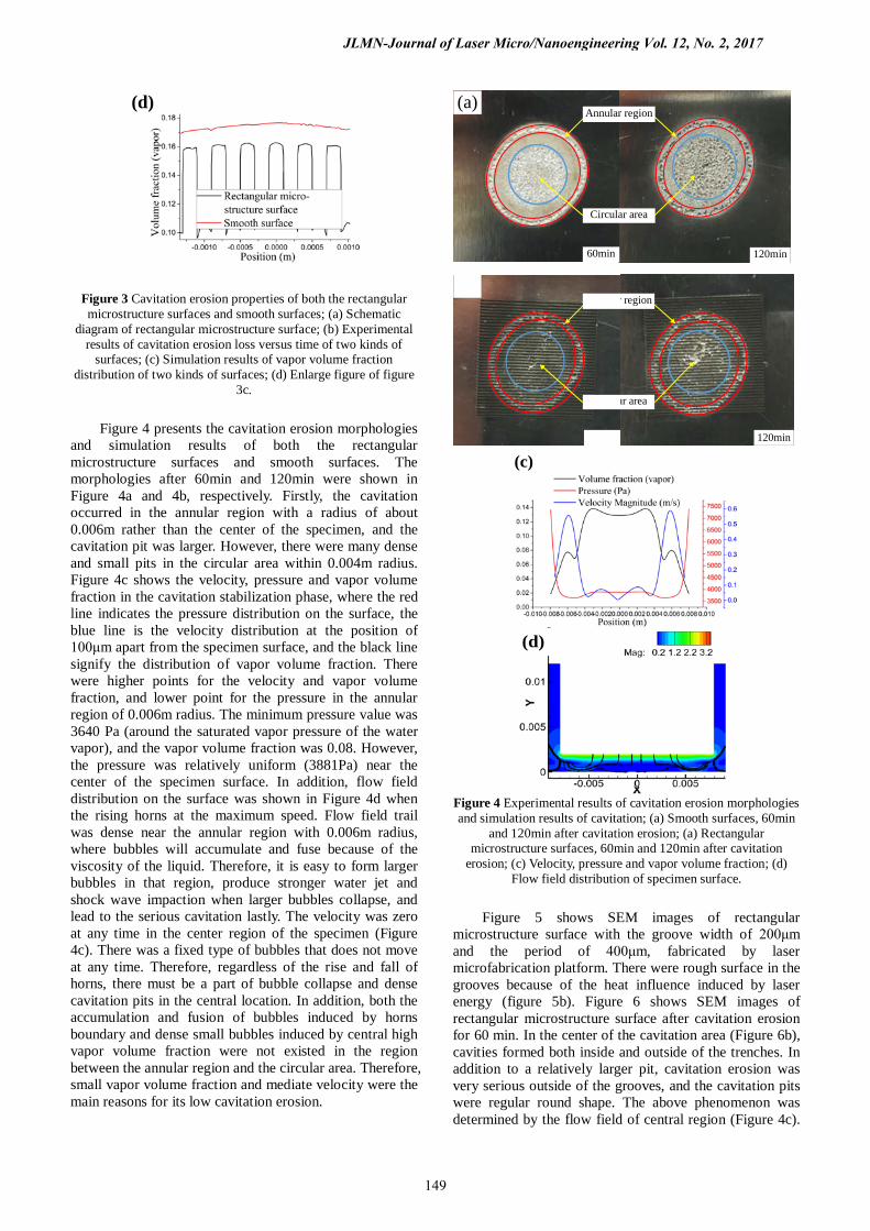
Figure 4 presents the cavitation erosion morphologies and simulation results of both the rectangular microstructure surfaces and smooth surfaces. The morphologies after 60min and 120min were shown in Figure 4a and 4b, respectively. Firstly, the cavitation occurred in the annular region with a radius of about 0.006m rather than the center of the specimen, and the cavitation pit was larger. However, there were many dense and small pits in the circular area within 0.004m radius. Figure 4c shows the velocity, pressure and vapor volume fraction in the cavitation stabilization phase, where the red line indicates the pressure distribution on the surface, the blue line is the velocity distribution at the position of 100μm apart from the specimen surface, and the black line signify the distribution of vapor volume fraction. There were higher points for the velocity and vapor volume fraction, and lower point for the pressure in the annular region of 0.006m radius. The minimum pressure value was 3640 Pa (around the saturated vapor pressure of the water vapor), and the vapor volume fraction was 0.08. However, the pressure was relatively uniform (3881Pa) near the center of the specimen surface. In addition, flow field distribution on the surface was shown in Figure 4d when the rising horns at the maximum speed. Flow field trail was dense near the annular region with 0.006m radius, where bubbles will accumulate and fuse because of the viscosity of the liquid. Therefore, it is easy to form larger bubbles in that region, produce stronger water jet and shock wave impaction when larger bubbles collapse, and lead to the serious cavitation lastly. The velocity was zero at any time in the center region of the specimen (Figure 4c). There was a fixed type of bubbles that does not move at any time. Therefore, regardless of the rise and fall of horns, there must be a part of bubble collapse and dense cavitation pits in the central location. In addition, both the accumulation and fusion of bubbles induced by horns boundary and dense small bubbles induced by central high vapor volume fraction were not existed in the region between the annular region and the circular area. Therefore, small vapor volume fraction and mediate velocity were the main reasons for its low cavitation erosion.
(a)
60min 120min
Circular area
Annular region
120min
ar area
r region
(c)
(d)
Figure 4 Experimental results of cavitation erosion morphologies and simulation results of cavitation; (a) Smooth surfaces, 60min
and 120min after cavitation erosion; (a) Rectangular microstructure surfaces, 60min and 120min after cavitation
erosion; (c) Velocity, pressure and vapor volume fraction; (d) Flow field distribution of specimen surface.
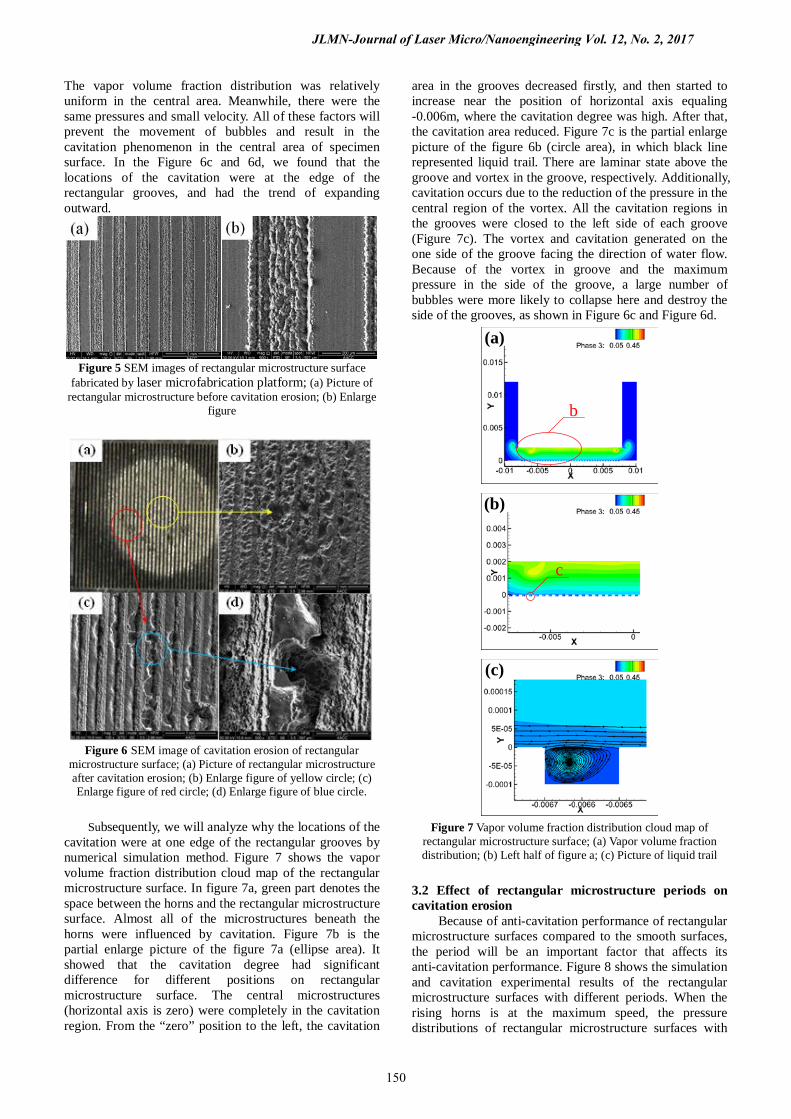
Figure 5 shows SEM images of rectangular
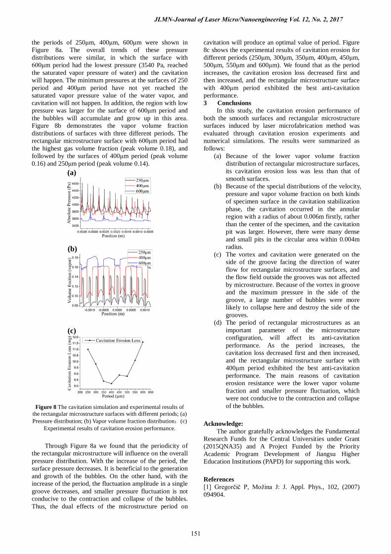
microstructure surface with the groove width of 200μm and the period of 400μm, fabricated by laser microfabrication platform. There were rough surface in the grooves because of the heat influence induced by laser energy (figure 5b). Figure 6 shows SEM images of rectangular microstructure surface after cavitation erosion for 60 min. In the center of the cavitation area (Figure 6b), cavities formed both inside and outside of the trenches. In addition to a relatively larger pit, cavitation erosion was very serious outside of the grooves, and the cavitation pits were regular round shape. The above phenomenon was determined by the flow field of central region (Figure 4c).
JLMN-Journal of Laser Micro/Nanoengineering Vol. 12, No. 2, 2017
149
The vapor volume fraction distribution was relatively uniform in the central area. Meanwhile, there were the same pressures and small velocity. All of these factors will prevent the movement of bubbles and result in the cavitation phenomenon in the central area of specimen surface. In the Figure 6c and 6d, we found that the locations of the cavitation were at the edge of the rectangular grooves, and had the trend of expanding outward.
Figure 5 SEM images of rectangular microstructure surface
fabricated by laser microfabrication platform; (a) Picture of rectangular microstructure before cavitation erosion; (b) Enlarge
figure
Figure 6 SEM image of cavitation erosion of rectangular microstructure surface; (a) Picture of rectangular microstructure after cavitation erosion; (b) Enlarge figure of yellow circle; (c) Enlarge figure of red circle; (d) Enlarge figure of blue circle.
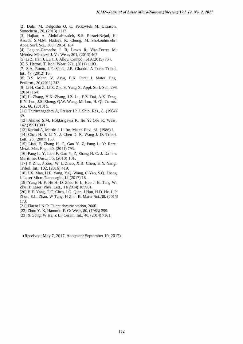
Subsequently, we will analyze why the locations of the
cavitation were at one edge of the rectangular grooves by numerical simulation method. Figure 7 shows the vapor volume fraction distribution cloud map of the rectangular microstructure surface. In figure 7a, green part denotes the space between the horns and the rectangular microstructure surface. Almost all of the microstructures beneath the horns were influenced by cavitation. Figure 7b is the partial enlarge picture of the figure 7a (ellipse area). It showed that the cavitation degree had significant difference for different positions on rectangular microstructure surface. The central microstructures (horizontal axis is zero) were completely in the cavitation region. From the “zero” position to the left, the cavitation
area in the grooves decreased firstly, and then started to increase near the position of horizontal axis equaling -0.006m, where the cavitation degree was high. After that, the cavitation area reduced. Figure 7c is the partial enlarge picture of the figure 6b (circle area), in which black line represented liquid trail. There are laminar state above the groove and vortex in the groove, respectively. Additionally, cavitation occurs due to the reduction of the pressure in the central region of the vortex. All the cavitation regions in the grooves were closed to the left side of each groove (Figure 7c). The vortex and cavitation generated on the one side of the groove facing the direction of water flow. Because of the vortex in groove and the maximum pressure in the side of the groove, a large number of bubbles were more likely to collapse here and destroy the side of the grooves, as shown in Figure 6c and Figure 6d.
(a)
b
(b)
c
(c)
Figure 7 Vapor volume fraction distribution cloud map of
rectangular microstructure surface; (a) Vapor volume fraction distribution; (b) Left half of figure a; (c) Picture of liquid trail
3.2 Effect of rectangular microstructure periods on cavitation erosion
Because of anti-cavitation performance of rectangular microstructure surfaces compared to the smooth surfaces, the period will be an important factor that affects its anti-cavitation performance. Figure 8 shows the simulation and cavitation experimental results of the rectangular microstructure surfaces with different periods. When the rising horns is at the maximum speed, the pressure distributions of rectangular microstructure surfaces with
JLMN-Journal of Laser Micro/Nanoengineering Vol. 12, No. 2, 2017
150
the periods of 250μm, 400μm, 600μm were shown in Figure 8a. The overall trends of these pressure distributions were similar, in which the surface with 600μm period had the lowest pressure (3540 Pa, reached the saturated vapor pressure of water) and the cavitation will happen. The minimum pressures at the surfaces of 250 period and 400μm period have not yet reached the saturated vapor pressure value of the water vapor, and cavitation will not happen. In addition, the region with low pressure was larger for the surface of 600μm period and the bubbles will accumulate and grow up in this area. Figure 8b demonstrates the vapor volume fraction distributions of surfaces with three different periods. The rectangular microstructure surface with 600μm period had the highest gas volume fraction (peak volume 0.18), and followed by the surfaces of 400μm period (peak volume 0.16) and 250μm period (peak volume 0.14).
(a)
(b)
(c)
Figure 8 The cavitation simulation and experimental results of the rectangular microstructure surfaces with different periods; (a) Pressure distribution; (b) Vapor volume fraction distribution;(c)
Experimental results of cavitation erosion performance.
Through Figure 8a we found that the periodicity of the rectangular microstructure will influence on the overall pressure distribution. With the increase of the period, the surface pressure decreases. It is beneficial to the generation and growth of the bubbles. On the other hand, with the increase of the period, the fluctuation amplitude in a single groove decreases, and smaller pressure fluctuation is not conducive to the contraction and collapse of the bubbles. Thus, the dual effects of the microstructure period on
cavitation will produce an optimal value of period. Figure 8c shows the experimental results of cavitation erosion for different periods (250μm, 300μm, 350μm, 400μm, 450μm, 500μm, 550μm and 600μm). We found that as the period increases, the cavitation erosion loss decreased first and then increased, and the rectangular microstructure surface with 400μm period exhibited the best anti-cavitation performance. 3 Conclusions
In this study, the cavitation erosion performance of both the smooth surfaces and rectangular microstructure surfaces induced by laser microfabrication method was evaluated through cavitation erosion experiments and numerical simulations. The results were summarized as follows:
(a) Because of the lower vapor volume fraction distribution of rectangular microstructure surfaces, its cavitation erosion loss was less than that of smooth surfaces.
(b) Because of the special distributions of the velocity, pressure and vapor volume fraction on both kinds of specimen surface in the cavitation stabilization phase, the cavitation occurred in the annular region with a radius of about 0.006m firstly, rather than the center of the specimen, and the cavitation pit was larger. However, there were many dense and small pits in the circular area within 0.004m radius.
(c) The vortex and cavitation were generated on the side of the groove facing the direction of water flow for rectangular microstructure surfaces, and the flow field outside the grooves was not affected by microstructure. Because of the vortex in groove and the maximum pressure in the side of the groove, a large number of bubbles were more likely to collapse here and destroy the side of the grooves.
(d) The period of rectangular microstructures as an important parameter of the microstructure configuration, will affect its anti-cavitation performance. As the period increases, the cavitation loss decreased first and then increased, and the rectangular microstructure surface with 400μm period exhibited the best anti-cavitation performance. The main reasons of cavitation erosion resistance were the lower vapor volume fraction and smaller pressure fluctuation, which were not conducive to the contraction and collapse of the bubbles.
Acknowledge: The author gratefully acknowledges the Fundamental
Research Funds for the Central Universities under Grant (2015QNA35) and A Project Funded by the Priority Academic Program Development of Jiangsu Higher Education Institutions (PAPD) for supporting this work.
References [1] Gregorčič P, Možina J: J. Appl. Phys., 102, (2007) 094904.
JLMN-Journal of Laser Micro/Nanoengineering Vol. 12, No. 2, 2017
151
[2] Dular M, Delgosha O. C, Petkovšek M: Ultrason. Sonochem., 20, (2013) 1113. [3] Hajian, A. Abdollah-zadeh, S.S. Rezaei-Nejad, H. Assadi, S.M.M. Hadavi, K. Chung, M. Shokouhimehr: Appl. Surf. Sci., 308, (2014) 184 [4] Laguna-Camacho J. R, Lewis R, Vite-Torres M, Méndez-Méndezd J. V : Wear, 301, (2013) 467. [5] Li Z, Han J, Lu J: J. Alloy. Compd., 619,(2015) 754. [6] S. Hattori, T. Itoh: Wear, 271, (2011) 1103. [7] S.A. Romo, J.F. Santa, J.E. Giraldo, A Toro: Tribol. Int., 47, (2012) 16. [8] B.S. Mann, V. Arya, B.K. Pant: J. Mater. Eng. Perform., 20,(2011) 213. [9] Li H, Cui Z, Li Z, Zhu S, Yang X: Appl. Surf. Sci., 298, (2014) 164. [10] L. Zhang, Y.K. Zhang, J.Z. Lu, F.Z. Dai, A.X. Feng, K.Y. Luo, J.S. Zhong, Q.W. Wang, M. Luo, H. Qi: Corros. Sci., 66, (2013) 5. [11] Thiruvengadam A, Preiser H: J. Ship. Res., 8, (1964) 39. [12] Ahmed S.M, Hokkirigawa K, Ito Y, Oba R: Wear, 142,(1991) 303. [13] Karimi A, Martin J. L: Int. Mater. Rev., 31, (1986) 1. [14] Chen H. S, Li Y. J, Chen D. R, Wang J. D: Tribol. Lett., 26, (2007) 153. [15] Lian, F, Zhang H. C, Gao Y. Z, Pang L. Y: Rare. Metal. Mat. Eng., 40, (2011) 793. [16] Pang L. Y, Lian F, Gao Y. Z, Zhang H. C: J. Dalian. Maritime. Univ., 36, (2010) 101. [17] Y Zhu, J Zou, W. L Zhao, X.B. Chen, H.Y. Yang: Tribol. Int., 102, (2016) 419. [18] J.X. Man, H.F. Yang, Y.Q. Wang, C Yan, S.Q. Zhang: J. Laser Micro/Nanoengin.,12,(2017) 16. [19] Yang H. F, He H. D, Zhao E. L, Hao J. B, Tang W, Zhu H: Laser. Phys. Lett., 11(2014) 105901. [20] H.F. Yang, T.C. Chen, J.G. Qian, J Han, H.D. He, L.P. Zhou, E.L. Zhao, W Tang, H Zhu: B. Mater Sci.,38, (2015) 173. [21] Fluent I N C: Fluent documentation, 2006. [22] Zhou Y. K, Hammitt F. G: Wear, 80, (1983) 299. [23] X Gong, W He, Z Li: Ceram. Int., 40, (2014) 7161.
(Received: May 7, 2017, Accepted: September 10, 2017)
JLMN-Journal of Laser Micro/Nanoengineering Vol. 12, No. 2, 2017
152


![MEMS gas flow sensor based on thermally induced cantilever ......using deflection-based (i.e., not frequency-based) sensing of the static microstructures [15], [16]. In this paper,](https://img.pdfslide.us/doc/110x75/60ae11ae4091ed538b7e130a/mems-gas-flow-sensor-based-on-thermally-induced-cantilever-using-deflection-based.jpg)