Embed Size (px)
Citation preview
LaSalle County Station2601 North 21 RoadMarseilles, Illinois 61341
Exeton Generation®
RA16-01110 CFR 50.4
March 10, 2016
U. S. Nuclear Regulatory CommissionAHN: Document Control DeskWashington, DC 20555-0001
LaSalle County Station, Unit 1Facility Operating License No. NPF-1 1NRC Docket No. 50-373
Subject: Unit 1 Cycle 17 Core Operating Limits Report (COLR)
In accordance with LaSalle County Station (LSCS) Technical Specifications (TS) 5.6.5.d,“CORE OPERATING LIMITS REPORT (COLR),” attached is a copy of the COLR for Unit 1.This report was revised for LSCS Unit 1, Cycle 17.
Exelon Generation Company, LLC makes no new or revised regulatory commitments in thisletter.
Should you have any questions concerning this letter, please contact Mr. Guy V. Ford, Jr.,Regulatory Assurance Manager, at (815) 415-2800.
Respectfully,
William J. TraftonSite Vice PresidentLaSalle County Station
Attachment: Core Operating Limits Report for LaSalle Unit 1 Cycle 17, Revision 0
cc: Regional Administrator - NRC Region IllNRC Senior Resident Inspector - LaSalle County Station

COLR LaSalle 1 Revision 16
Core Operating Limits Report for
LaSalle Unit I
Cycle 17 Revision 0
LaSalle Unit 1 Cycle 17Page 1 of 21
COLR LaSalle 1 Revision 16
Table of Contents
Page
Revision History 3
List of Tables 4
1. References 5
2. Terms and Definitions 6
3. General Information 7
4. Average Planar Linear Heat Generation Rate 8
5. Operating Limit Minimum Critical Power Ratio 9
5.1. Manual Flow Control MCPR Limits 9
5.1.1. Power-Dependent MCPR 9
5.1.2. Flow-Dependent MCPR 9
5.2. Scram Time 10
5.3. Recirculation Flow Control Valve Settings 10
6. Linear Heat Generation Rate 14
7. Rod Block Monitor 17
8. Traversing In-Core Probe System 18
8.1. Description 18
8.2. Bases 18
9. Stability Protection Setpoints 19
10. Modes of Operation 20
11. Methodology 21
LaSalle Unit 1 Cycle 17Page 2 of 21

COLR LaSalle I Revision 16
Revision History
Record of COLR LaSalle I Cycle 17 Revisions
Revision Description
16 Initial issuance for Li Cl 7.
LaSalle Unit 1 Cycle 17Page 3 of 21

COLR LaSalle 1 Revision 16
List of Tables
Table 3-1 Cycle Exposure Range Definitions 7
Table 4-1 MAPLHGR for GNF2 Fuel 8
Table 4-2 MAPLHGR SLO Multiplier for GNF2 Fuel, BOC to EOC 8
Table 5-1 Scram Times Required for Option A and Option B Application at Notch Position 39 10
Table 5-2 Operating Limit Minimum Critical Power Ratio (OLMCPR) for GNF2 Fuel 11
Table 5-3 Power-Dependent MCPR Multipliers (Kp) for GNF2 Fuel,DLO and SLO, SOC to EOC, Option A and Option B 12
Table 5-4 DLO Flow-Dependent MCPR Limits (MCPRF) for GNF2 Fuel,BOC to EOC, All Application Groups, Option A and Option B 13
Table 5-5 SLO Flow-Dependent MCPR Limits (MCPRF) for GNF2 Fuel,BOC to EOC, All Application Groups, Option A and Option B 13
Table 6-1 LHGR Limit for GNF2 Fuel 14
Table 6-2 Power-Dependent LHGR Multipliers (LHGRFACp) for GNF2 Fuel,DLO and SLO, SOC to EOC 15
Table 6-3 Flow-Dependent LHGR Multipliers (LHGRFACF) for GNF2 Fuel,BOC to EOC, Pressurization (1 TCVITSV Closed or 005), All Application Groups 16
Table 6-4 Flow-Dependent LHGR Multipliers (LHGRFACF) for GNF2 Fuel,SOC to EOC, No Pressurization (All TCVITSV In-Service), All Application Groups 16
Table 7-1 Rod Block Monitor Setpoints 17
Table 9-1 OPRM PBDA Trip Setpoints 19
Table 10-1 Allowed Modes of Operation and EOOS Combinations 20
LaSalle Unit 1 Cycle 17Page 4 of 21

COLR LaSalle 1 Revision 16
1. References
1. Exelon Generation Company, LLC Docket No. 50-373 LaSalle County Station, Unit 1, Facility Operating
License No. NPF-11.
2. NRC Generic Letter 88-16, from D. M. Crutchfield to All Power Reactor Licensees and Applicants, “Removal
of Cycle-Specific Parameter Limits from Technical Specifications,” October 3, 1988.
3. Exelon Nuclear Fuels Letter NFM:MW:01 -01 06, from A. Giancatarino to J. Nugent, “LaSalle Unit I and Unit
2 Rod Block Monitor COLR Setpoint Change,” April 3, 2001.
4. GE Nuclear Energy Report NEDC-32694P-A, Revision 0, ‘Power Distribution Uncertainties for Safety Limit
MCPR Evaluations,” August 1999.
5. GE Nuclear Energy Document GE-NE-Al 300384-07-01, Revision 1, “LaSalle County Station Power Uprate
Project Task 201: Reactor Power/Flow Map”, September 1999.
6. GE Hitachi Nuclear Energy Report, GE-NE-0000-0099-8344-R1, Revision 1, “Exelon Nuclear LaSalle Units
1 and 2 Thermal Power Optimization Task T0201: Operating Power/Flow Map”, November 2009.
7. GNF Report 001 N4873, Revision 0, “Supplemental Reload Licensing Report for LaSalle Unit 1 Reload 16
Cycle 17,” January 2016.
8. GNF Letter MFN 13-029, from B. R. Moore to Document Control Desk, “GNF2 Advantage Generic
Compliance with NEDE-2401 1-P-A (GESTAR II), NEDC-33270P, Revision 5, May 2013,” May 24, 2013.
(ADAMS Accession No. ML13148A318)
9. Exelon Transmittal ES1500023, Revision 0, “LaSalle 1 Cycle 17 Final Resolved OPL-3 Parameters,”
September 17, 2015.
10. GNF Letter DRF A12-00038-3, Vol. 4, from G.A. Watford to Distribution, “Scram Times versus NotchPosition,” May 22, 1992.
11. GEH Nuclear Energy DRF Section 0000-0151-0765, Revision 0, “Application of SLO SLMCPR’, February
12, 2013.
12. NRC Letter from D. M. Skayto I. M. Johnson, “Issuance of Amendments (TAC NOS. M95156 and
M95157),” October 29, 1996.
LaSalle Unit 1 Cycle 17Page 5 of 21

COLR LaSalle 1 Revision 16
2. Terms and Definitions
ARTS Average Power Range Monitor, Rod Block Monitor and Technical SpecificationImprovement Program
BOC Beginning of cycleBWR Boiling water reactorCOLR Core operating limits reportCRD Control rod drive mechanismDLO Dual loop operationELLLA Extended load line limit analysisEOC End of cycleEOOS Equipment out of serviceEOR17 End of rated operation for Cycle 17FFWTR Final feedwater temperature reductionFWHOOS Feedwater heater out of serviceGNF Global Nuclear Fuels - AmericasICE Increased core flow
Power-dependent MCPR MultiplierL1C17 LaSaIle Unit 1 Cycle 17LHGR Linear heat generation rateLHGRFACF Flow-dependent LHGR multiplierLHGRFACP Power-dependent LHGR multiplierLPRM Local power range monitorMAPLHGR Maximum average planar linear heat generation rateMCPR Minimum critical power ratioMCPRF Flow-dependent MCPRMELLLA Maximum extended load line limit analysisMOC Middle of Cycle Point for Licensing PurposesMSIVOOS Main steam isolation valve out of serviceOLMCPR Operating limit minimum critical power ratioOCS Out of serviceOPRM Oscillation power range monitorPBDA Period based detection algorithmPLUCOS Power load unbalance out of servicePROOS Pressure regulator out of serviceRPTOOS Recfrculation pump trip out of serviceRWE Rod withdrawal errorSLMCPR Safety limit minimum critical power ratioSLO Single loop operationSRVOOS Safety-relief valve out of serviceTBV Turbine bypass valveTBVOOS Turbine bypass valve out of serviceTCV Turbine control valveTCVIS All Turbine Control Valves/Turbine Stop Valves in-serviceTCVSC Turbine control valve slow closureTIP Traversing in-core probeTIPOOS Traversing in-core probe out of serviceTSV Turbine stop valve3DM 3D Monicore
LaSalle Unit 1 Cycle 17Page 6 of2l

COLR LaSalle 1 Revision 16
3. General Information
Power and flow dependent limits are listed for various power and flow levels. Linear interpolation is to be used to
find intermediate values.
Rated core flow is 108.5 Mlbm/hr. Operation up to 105% rated flow is licensed for this cycle. Licensed rated
thermal power is 3546 MWth.
For thermal limit monitoring above 100% rated power or 100% rated core flow, the 100% rated power and the
100% core flow values, respectively, can be used unless otherwise indicated in the applicable table.
Table 3-1 defines the three exposure ranges used in the COLR. The end of rated (EOR) exposure is defined as
the cycle exposure corresponding to all rods out, 100% power/i 00% flow, and normal feedwater temperature.
The term (EDR — 2211 MWU/ST) means the EOR exposure minus 2211 MWd/ST of exposure. The value of the
EOR exposure is based on actual plant operation and is thus determined from projections to this condition made
near, but before, the time when the EOR1 7 — 2211 MWd/ST exposure will be reached. For cycle exposure
dependent limits at the exact MOC exposure, the more limiting of the BOC to MOC and the MDC to EOC limits
should be used. This can be achieved by applying the MDC to EOC limits to the MOC point as all cycle exposure
dependent limits in the MOC to EOC limit sets are the same as, or more limiting than, those in the BOC to MOC
limit sets.
Table 3-1 Cycle Exposure Range Definitions(Reference 7)
Nomenclature Cycle Exposure Range
BOC to MDC BOC17 to fEORI7 —2211 MWd/ST)
MDC to EOC (EOR17 —2211 MWU/ST) to EOC17
SOC to EOC 60C17 to EOC17
LaSalle Unit 1 Cycle 17Page 7 of 21

COLR LaSalle 1 Revision 16
4. Average P’anar Linear Heat Generation Rate
Technical Specification Sections 3.2.1 and 3.4.1
MAPLHGR values as a function of average planar exposure are given in Table 4-1. During SLO, these limits are
multiplied by the SLO multiplier listed in Table 4-2. The MAPLHGR values in Table 4-1 along with the MAPLHGR
SLO multiplier in Table 4-2 provide coverage for all modes of operation.
Table 4-1 MAPLHGR for GNF2 Fuel(Reference 7)
Avg. Planar MAPLHGRExposure (kW/FT)(GWd/ST)
0.00 13.78
17.15 13.7860.78 6.8763.50 5.50
Table 4-2 MAPLHGR SLO Multiplier for GNF2 Fuel,BOC to EOC
(Reference 7)
SLOFuel Type MAPLHGR
MultiplierGNF2 0.78
LaSalle Unit 1 Cycle 17Page 8 of 21
COLR LaSalle 1 Revision 16
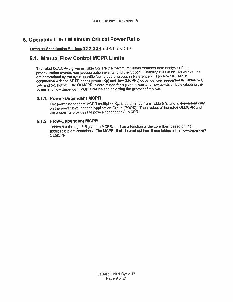
5. Operating Limit Minimum Critical Power Ratio
Technical Specification Sections 3.2.2, 3.3.4.1, 3.4.1, and 3.7.7
5.1. Manual Flow Control MCPR Limits
The rated OLMCPRs given in Table 5-2 are the maximum values obtained from analysis of thepressurization events, non-pressurization events, and the Option Ill stability evaluation. MCPR valuesare determined by the cycle-specific fuel reload analyses in Reference 7. Table 5-2 is used inconjunction with the ARTS-based power (Kp) and flow (MCPRF) dependencies presented in Tables 5-3,5-4, and 5-5 below. The OLMCPR is determined for a given power and flow condition by evaluating thepower and flow dependent MCPR values and selecting the greater of the two.
5.1.1. Power-Dependent MCPRThe power-dependent MCPR multiplier, K, is determined from Table 5-3, and is dependent onlyon the power level and the Application Group (EOOS). The product of the rated OLMCPR andthe proper K provides the power-dependent OLMCPR.
5.1.2. Flow-Dependent MCPRTables 5-4 through 5-5 give the MCPRF limit as a function of the core flow, based on theapplicable plant conditions. The MCPRF limit determined from these tables is the flow-dependentOLMCPR.
LaSalle Unit 1 Cycle 17Page 9 of 21
COLR LaSalle 1 Revision 16
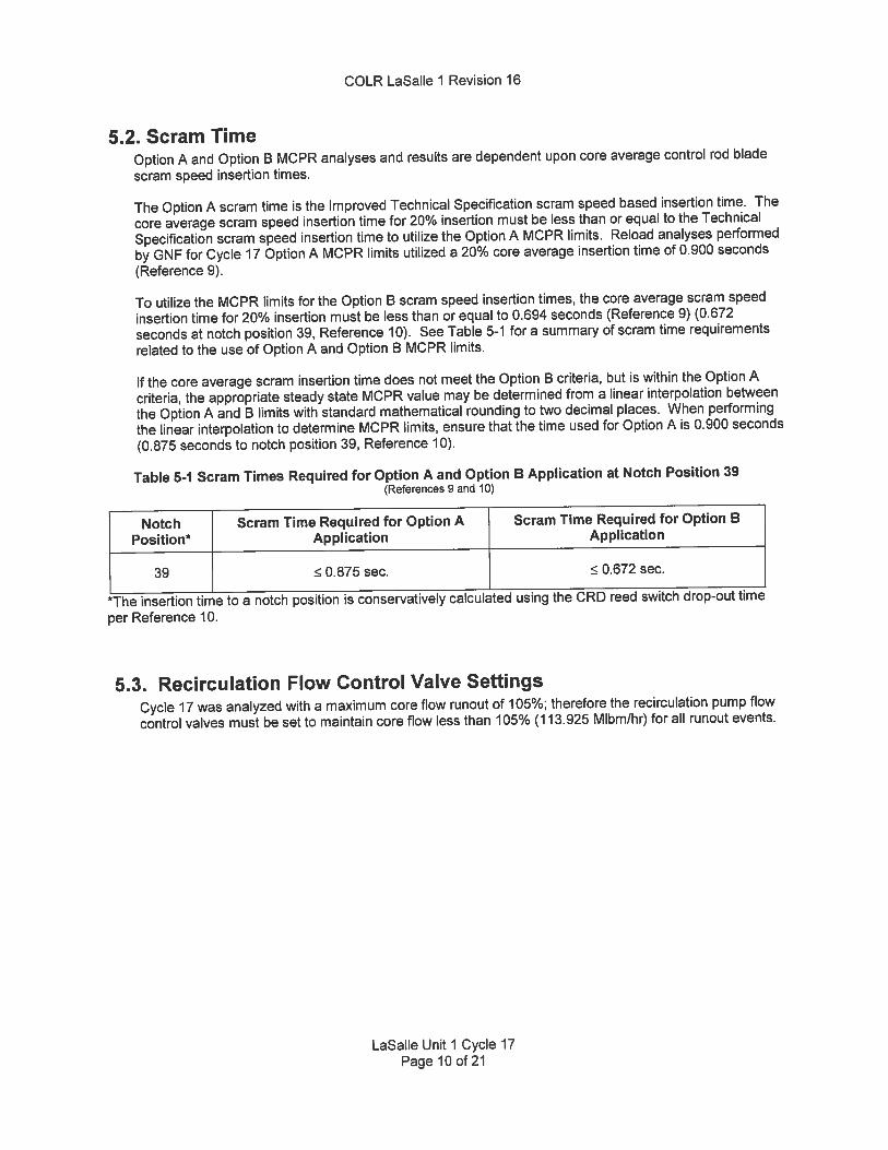
5.2 Scram TimeOption A and Option B MCPR analyses and results are dependent upon core average control rod blade
scram speed insertion times.
The Option A scram time is the Improved Technical Specification scram speed based insertion time. The
core average scram speed insertion time for 20% insertion must be less than or equal to the Technical
Specification scram speed insertion time to utilize the Option A MCPR limits. Reload analyses performed
by GNF for Cycle 17 Option A MCPR limits utilized a 20% core average insertion time of 0.900 seconds
(Reference 9).
To utilize the MCPR limits for the Option B scram speed insertion times, the core average scram speed
insertion time for 20% insertion must be less than or equal to 0.694 seconds (Reference 9) (0.672
seconds at notch position 39, Reference 10). See Table 5-1 for a summary of scram time requirements
related to the use of Option A and Option B MCPR limits.
lithe core average scram insertion time does not meet the Option B criteria, but is within the Option A
criteria, the appropriate steady state MCPR value may be determined from a linear interpolation between
the Option A and B limits with standard mathematical rounding to two decimal places. When performing
the linear interpolation to determine MCPR limits, ensure that the time used for Option A is 0.900 seconds
(0.875 seconds to notch position 39, Reference 10).
Table 5-1 Scram Times Required for Option A and Option B Application at Notch Position 39(References 9 and 10)
Notch Scram Time Required for Option A Scram Time Required for Option BPosition* Application Application
39 0.875 sec. 0.672 sec.
The insertion time to a notch position is conservatively calculated using the CRD reed switch drop-out time
per Reference 10.
5.3. Recirculation Flow Control Valve SettingsCycle 17 was analyzed with a maximum core flow runout of 105%; therefore the recirculation pump flow
control valves must be set to maintain core flow less than 105% (113.925 Mlbm/hr) for all runout events.
LaSalle Unit 1 Cycle 17Page 10 of 21
COLR LaSalle 1 Revision 16
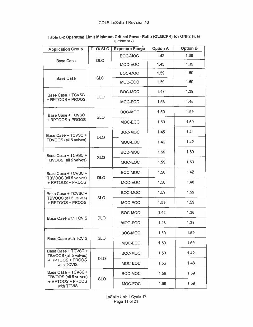
Table 5-2 Operating Limit Minimum Critical Power Ratio (OLMCPR) for GNF2 Fuel(Reference 7)
Application Group DLO/ SLO Exposure Range Option A Option B
BOC-MOC 1.42 1.38Base Case DLO
MOC-EOC 1.43 1.39
BOC-MOC 1.59 1.59Base Case SLO
MOC-EOC 1.59 1.59
BOC-MOC 1.47 1.39Base Case + TCVSC DLO
+ RPTOOS + PROOSMOC-EOC 1.53 1.45
BOC-MOC 1.59 1.59Base Case + TCVSC SLO
+ RPTOOS + PRODSMOC-EOC 1.59 1.59
BOC-MOC 1.45 1.41Base Case + TCVSC + OLDTBVOOS (all 5 valves)
MOC-EOC 1.46 1.42
BOC-MOC 1.59 1.59Base Case + TCVSC + SLOTBVOOS (all 5 valves)
MOC-EOC 1.59 1.59
Base Case + TCVSC ÷ BOC-MOC 1.50 1.42
TBVOOS (all 5 valves) DLO+ RPTOOS + PRODS MOC-EOC 1.56 1.48
Base Case + TCVSC -I- BOC-MOC 1.59 1.59
TBVDOS (all 5 valves) SLO+RPTOQS+PROOS MOC-EOC 1.59 1.59
BOC-MOC 1.42 1.38
Base Case with TCVIS DLOMOC-EOC 1.43 1.39
BOC-MOC 1.59 1.59
Base Case with TCVIS SLOMOC-EOC 1.59 1.59
Base Case + TCVSC +BOC-MOC 1.50 1.42
TBVOOS (all 5 valves)+ RPTOOS + PRODS DLO
with TCVIS MOC-EOC 1.56 1.48
Base Case + TCVSC + BOC-MOC 1.59 1.59TBVOOS (all 5 valves) SLO÷ RPTOOS ÷ PRODS
with TCVIS MOC-EOC 1.59 1.59
LaSalle Unit 1 Cycle 17Page 11 of 21

COLR LaSalle 1 Revision 16
Table 5-3 Power-Dependent MCPR Multipliers (Kp) for GNF2 Fuel,DLO and SLO, SOC to EOC, Option A and Option B
(Reference 7)
K1,, MCPR Limit Multiplier (as a function of ¾ rated power)Application Group
0% P 25% P 45% P 60% P 85% P 85.01%P 100% P
Base Case 1.156 1.156 1.156 1.156 1.045 1.045 1.000
Base Case + TCVSC + 1.244 1.244 1.178 1.164 1.077 1.045 1.000RPTOOS + PROOS
Base Case + TCVSC + 1.244 1.244 1.178 1.164 1.077 1.045 1.000TBVOOS (all 5 valves)
Base Case + TCVSC +
TBVOOS (all 5 valves) 1.244 1.244 1.178 1.164 1.077 1.069 1.000
+ RPTOOS + PROOS
BaseCasewithTCVlS 1.156 1.156 1.156 1.156 1.045 1.045 1.000
Base Case + TCVSC +
TBVOOS (all 5 valves)1.244 1.244 1.178 1.164 1.077 1.069 1.000
+ RPTOOS + PROOSwith TCVIS
LaSalle Unit 1 Cycle 17Page 12 of2l
COLR LaSalle 1 Revision 16
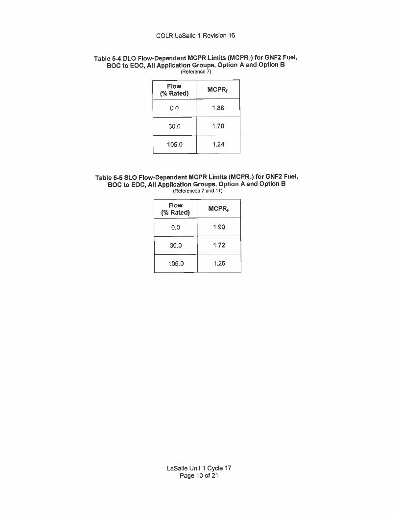
Table 54 DLO Flow-Dependent MCPR Limits (MCPRF) for GNF2 Fuel,BOC to EOC, All Application Groups, Option A and Option B
(Reference 7)
Flow(% Rated) MCPRF
0.0 1.88
30.0 1.70
105.0 1.24
Table 5-5 SLO Flow-Dependent MCPR Limits (MCPRF) for GNF2 Fuel,BOC to EOC, All Application Groups, Option A and Option B
(References 7 and 11)
Flow(% Rated) IvICPRF
0.0 1.90
30.0 1.72
105.0 1.26
LaSalle Unit 1 Cycle 17Page 130121

COLR LaSalle 1 Revision 16
6. Linear Heat Generation Rate
Technical Specification Sections 3.2.3 and 3.4.1
The LHGR limit is the product of the exposure dependent LHGR limit from Table 6-1 and the minimum of the
power dependent LHGR Factor, LHGRFACP, or the flow dependent LHGR Factor, LHGRFACF as applicable. The
LHGRFACP multiplier is determined from Table 6-2. The LHGRFACF multiplier is determined from Table 6-3 or
Table 6-4. The SLO multipliers in Table 6-3 and Table 6-4 have been limited to a maximum value of 0.78, the
SLO LHGR multiplier for GNF2 fuel.
Table 6-1 LHGR Limit for GNF2 Fuel(Reference 8)
Peak Pellet Exposure I U02 LHGR LimitSee Table B-i of Reference 8
Peak Pellet Exposure Most LimitingGadolinia LHGR
LimitSee Table B-2 of Reference 8
LaSalle Unit 1 Cycle 17Page 14 of 21

COLR LaSalle 1 Revision 16
Table 6-2 Power-Dependent LHGR Multipliers (LHGRFACp) for GNF2 Fuel,DLO and SLO, BOC to EOC
(Reference 7)
LHGRFACP (as a function of ¾ rated power)Application Group
0% P 25% P 45% P 60% P 85% P 100% P
Base Case 0.608 0.608 0.713 0.791 0.922 1.000
Base Case + TCVSC +0.608 0.608 0.703 0.761 0.831 1.000
RPTOOS + PROOS
Base Case + TCVSC +0.608 0.608 0.713 0.791 0.922 1.000
TBVOOS (all 5 valves)
Base Case + TCVSC +
TBVOOS (all 5 valves) 0.608 0.608 0.703 0.761 0.822 1.000+ RPTOOS + PROOS
BaseCasewithTCVlS 0.608 0.608 0.713 0.791 0.922 1.000
Base Case + TCVSC +
TBVOOS (all 5 valves) 0.608 0.608 0.703 0.761 0.822 1.000+ RPTOOS + PROOS
with TCVIS
LaSalle Unit 1 Cycle 17Page 15 of 21
COLR LaSalle 1 Revision 16
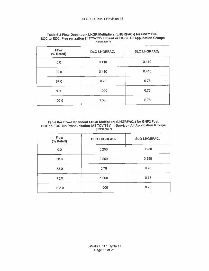
Table 6-3 Flow-Dependent LHGR Multipliers (LHGRFACF) for GNF2 Fuel,BOG to EOC, Pressurization (1 TCVITSV Closed or OOS), All Application Groups
(Reference 7)
Flow DLO LHGRFACF SLO LHGRFACF(% Rated)
0.0 0.110 0.110
30.0 0.410 0.410
67.0 0.78 0.78
89.0 1.000 0.78
105.0 1.000 0.78
Table 6-4 Flow-Dependent LHGR Multipliers (LHGRFACF) for GNF2 Fuel,BOC to EOC, No Pressurization (All TCV/TSV In-Service), All Application Groups
(Reference 7)
Flow DLO LHGRFACF SLO LHGRFACF(% Rated)
0.0 0.250 0.250
30.0 0.550 0.550
53.0 0.78 0.78
75.0 1.000 0.78
105.0 1.000 0.78
LaSalle Unit 1 Cycle 17Page 16 of 21
COLR LaSalle 1 Revision 16
7. Rod Block Monitor
Technical Specification Sections 3.3.2.1 and 3.4.1
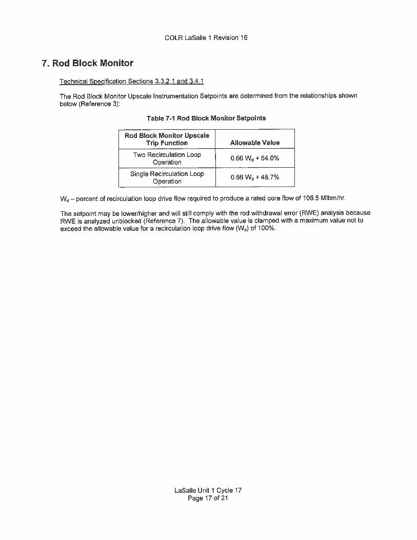
The Rod Block Monitor Upscale Instrumentation Setpoints are determined from the relationships shownbelow (Reference 3):
Table 7-f Rod Block Monitor Setpoints
Rod Block Monitor UpscaleTrip Function Allowable Value
Two Recirculation Loop 0.66 Wd + 54.0%Operation
Single Recirculation Loop 0.66 Wd + 48.7%Operation
Wd — percent of recirculation loop drive flow required to produce a rated core flow of 108.5 Mlbm/hr.
The setpoint may be lower/higher and will still comply with the rod withdrawal error (RWE) analysis becauseRWE is analyzed unblocked (Reference 7). The allowable value is clamped with a maximum value not toexceed the allowable value for a recirculation loop drive flow (Wd) of 100%.
LaSalle Unit 1 Cycle 17Page 17 of 21

COLR LaSalle 1 Revision 16
8. Traversing In-Core Probe System (Reference 12)
8.1. Description
When the traversing in-core probe (TIP) system (for the required measurement locations) is used for
recalibration of the LPRM detectors and monitoring thermal limits, the TIP system shall be operable with
the following:
1. movable detectors, drives and readout equipment to map the core in the required measurement
locations, and2. indexing equipment to allow all required detectors to be calibrated in a common location.
The following applies for use with 3DM (Reference 4):
The total number of failed and/or bypassed LPRMs does not exceed 25%. In addition, no more than 14
TIP channels can be OOS (failed or rejected).
Otherwise, with the TIP system inoperable, suspend use of the system for the above applicable
calibration functions.
8.2. Bases
The operability of the TIP system with the above specified minimum complement of equipment ensures
that the measurements obtained from use of this equipment accurately represent the spatial neutron flux
distribution of the reactor core. The normalization of the required detectors is performed internal to the
core monitoring software system.
LaSalle Unit 1 Cycle 17Page 18 of 21

COLR LaSalle 1 Revision 16
9. Stability Protection Setpoints
Technical Specification Section 3.3.1.3
Table 9-i OPRM PBDA Trip Setpoints(Reference 7)
Corresponding MaximumPBDA Trip Amplitude Setpoint (Sp) Confirmation Count Setpoint (Np)
1.15 16
The PBDA is the only OPRM setting credited in the safety analysis as documented in the licensing basis for
the OPRM system.
The OPRM PBDA trip settings are applicable when the OPRM system is declared operable, and the associated
Technical Specifications are implemented.
LaSalle Unit 1 Cycle 17Page 190121

COLR LaSalle 1 Revision 16
JO. Modes of OperationThe allowed modes of operation with combinations of equipment out-of-service are as described below
(Reference 7).Table 10-1 Allowed Modes of Operation and EOOS Combinations
(Reference 7)
Equipment Out of Service Options (1) (2) (3) (4) Short Name
Base Case (Option A or B) Base
Base Case + SLO (Option A or B) Base SLO
Base Case + TCVSC + RPTOOS + PROOS (Option A or B) Combined EOOS 1
Base Case + TCVSC + RPTOOS + PROOS + SLO (Option A or B) Combined BOOS 1 SLO
Base Case + TCVSC -i- TBVOOS (all 5 valves) (Option A or B) Combined BOOS 2
Base Case ÷ TCVSC + TBVOOS (all 5 valves) + SLO (Option A or B) Combined BOOS 2 SLO
Base Case + TCVSC + TBVOOS (all 5 valves) + RPTOOS ÷ PROOS(Option A or B)
Combined EOOS 3
Base Case + TCVSC + TBVOOS (all 5 valves) + RPTOOS + PROOS + SLO.
Combined EOOS 3 SLO(Option A or B)
Base Case with TCVIS (Option A or B) Base TCVIS
Base Case + SLO with TCVIS (Option A or B) Base SLO TCVIS
Base Case + TCVSC + TEVOOS (aN 5 valves) + RPTOOS + PROOS with Combined EOOS 3
TCVIS (Option A or B) TCVIS
Base Case + TCVSC + TBVOOS (all 5 valves) + RPTOOS + PRODS + SLO Combined BOOS 3 SLO
with TCVIS (Option A or B) TCVIS
(1) Base case includes 1 SRVOOS + 1 TCVITSV 005 + FWHOOS/FFWTR + 1 MSIVOOS + 2 TBVOOS + PLUOOS, and
also includes 1 TIPOOS (up to 14 TIP channels not available) any time during the cycle, including BOC, and upto 25% of the
LPRMs out-of-service (failed or rejected) (Reference 4). The one Stuck Closed TCV and/or TSV EOOS conditions require
power level 85% ot rated. The one MSIVOOS condition is also supported as long as thermal power is maintained 75% of
the rated (Reference 7). The FWHOOS/FFWTR analyses cover a maximum reduction of 100°F for the feedwater temperature.
A nominal LPRM calibration interval of 2000 EFPH (2500 EFPH maximum) is supported for LICJ7.
(2) TBVOOS (all 5 valves) is the turbine bypass system out of service which means that 5 TBV5 are !i2 credited for fast
opening and 3 TBVs are j credited to open in pressure control. For the 2 TBVOOS condition that is a part of the base case,
the assumption is that both of the TBV5 do not open on any signal and thus remain shut for the transients analyzed (i.e. 3
TBVs are credited to open in pressure control). The MCFL is currently set at 126.6 (Reference 9) and will only allow opening of
TBV’s #1, #2, #3, and #4 during a slow pressurization event. The MCFL does not use the TBV position feedback signal to
know how many TBVs have opened or how far each has opened. The #5 TBV is not available based on the current MCFL
setpoint and thus cannot be used as one of the credited valves to open in pressure control.
(3) The ÷ sign that is used in the Equipment Out of Service Option / Application Group descriptions designates an and/or”.
(4) All EOOS Options (Reference 7 Application Groups) are applicable to ELLLA, MELLLA, ICE and Coastdown realms of
operation with the exception that SLO is not applicable to MELLLA or CF (References 5 and 6). The MOC to EOC exposure
range limit sets are generated by GNF to include application to coastdown operation (Methodology Reference 1).
LaSalle Unit 1 Cycle 17Page 20 of 21

COLR LaSalle 1 Revision 16
11. MethodologyThe analytical methods used to determine the core operating limits shall be those previously reviewed andapproved by the NRC, specifically those described in the following documents:
1. GNF Report NEDE-24011-P-A-22 (Revision 22), General Electric Standard Application for Reactor Fuel,”November 2015 and the U.S. Supplement NEDE-2401 1-P-A-22-US, November 2015.
2. BWR Owners’ Group Report NEDO-32465-A (Revision 0), ‘BWR Owners’ Group Reactor Stability Detect andSuppress Solutions Licensing Basis Methodology and Reload Applications,” August 1996.
LaSalle Unit 1 Cycle 17Page 21 of 21