Embed Size (px)
Citation preview

Larson Systems Inc. Phone: 763-780-2131 10073 Baltimore Street N.E. Toll Free: 1-877-780-2131 Minneapolis, MN 55449-4425 Fax: 763-780-2182 www.larsonsystems.com E-mail: [email protected]
Larson Systems Inc.
060-1000-0066-00E FLASH 11 and 24 Automatic Testers
User Manual
Current for Software Version 2.64 DAQ BOARD Firmware Version 2.62
Flash Series User Manual Page of 2 060-1000-0066-00E 2
About This Manual This manual could contain technical inaccuracies or typographical errors. Changes are periodically made to the information contained herein. These changes will be incorporated in new editions of the manual. Copyright © 2012 Larson Systems Inc. All rights reserved. No part of this manual may be reproduced by any means without written permission of the author, except portions necessary for internal use only by the purchaser of the LSI system.
Flash Series User Manual Page of 3 060-1000-0066-00E 3
Table Of Contents
1 INTRODUCTION................................................................................................................... 5
1.1 FLASH 11 and FLASH 24...............................................................................................................................7
1.2 FLASH Software Packages ...........................................................................................................................9 1.2.1 Basic .........................................................................................................................................................9 1.2.2 Extra .........................................................................................................................................................9 1.2.3 Pro Spring.................................................................................................................................................9 1.2.4 Pro Material ..............................................................................................................................................9 1.2.5 Fatigue Testing .........................................................................................................................................9 1.2.6 Pro Ultimate ............................................................................................................................................10
1.3 Smart Interchangeable Load Cells .............................................................................................................10
1.4 Whisper Servo Drive....................................................................................................................................10
1.5 Web Service, Network, and Printer Connection........................................................................................10
1.6 Additional Options and Equipment............................................................................................................10
2 USING THIS MANUAL ....................................................................................................... 11
3 SAFETY AND USE GUIDELINES...................................................................................... 11
3.1 Important Considerations ...........................................................................................................................11
3.2 The Safety Shield Enclosure.......................................................................................................................11
3.3 Abort Test and Emergency Stop ................................................................................................................11
3.4 Windows 7 Automatic Logon......................................................................................................................12
4 MACHINE SETUP............................................................................................................... 12
4.1 On and Off Procedure..................................................................................................................................12
4.2 The Main Display (Manual Mode) ...............................................................................................................13 4.2.1 Home Tester (Initialize)...........................................................................................................................13 4.2.2 Compression and Extension...................................................................................................................15 4.2.3 Navigation Toolbar..................................................................................................................................17 4.2.4 The Jog Bar ............................................................................................................................................18 4.2.5 Force vs. Length Graph ..........................................................................................................................18 4.2.6 Length.....................................................................................................................................................18 4.2.7 Force.......................................................................................................................................................18 4.2.8 Instructions .............................................................................................................................................18 4.2.9 Abort Test ...............................................................................................................................................18 4.2.10 Shut Down ............................................................................................................................................18 4.2.11 Re-Initialize ...........................................................................................................................................19
5 MAIN MENU APPLICATIONS............................................................................................ 19
5.1 Manual Mode ................................................................................................................................................20 5.1.1 Using the Length Display........................................................................................................................20 5.1.2 Using the Force Display..........................................................................................................................21
Flash Series User Manual Page of 4 060-1000-0066-00E 4
5.1.3 Run A Basic Test ....................................................................................................................................22
5.2 Program Mode..............................................................................................................................................22 5.2.1 New.........................................................................................................................................................23 5.2.2 Check......................................................................................................................................................23 5.2.3 Program..................................................................................................................................................23 5.2.4 Sorting ....................................................................................................................................................30 5.2.5 Program Mode Preferences (Prefs)........................................................................................................34
5.3 Quick Test.....................................................................................................................................................36 5.3.1 Program..................................................................................................................................................37 5.3.2 Actual Data .............................................................................................................................................38 5.3.3 Quick Test Preferences (Prefs) ..............................................................................................................39
5.4 File .................................................................................................................................................................41 5.4.1 New.........................................................................................................................................................41 5.4.2 Open .......................................................................................................................................................41 5.4.3 Save........................................................................................................................................................43 5.4.4 Save As…...............................................................................................................................................43
5.5 Automatic Mode ...........................................................................................................................................44 5.5.1 Using a Predefined Program ..................................................................................................................44 5.5.2 Select How Results Are Compiled..........................................................................................................44 5.5.3 Viewing Results ......................................................................................................................................45 5.5.4 Automatic Mode Preferences (Prefs)......................................................................................................46 5.5.5 Production Monitor..................................................................................................................................47 5.5.6 Display Features and Operation .............................................................................................................48
5.6 Quick Launch ...............................................................................................................................................49 5.6.1 Launch ....................................................................................................................................................50 5.6.2 Configure ................................................................................................................................................51 5.6.3 Add .........................................................................................................................................................52
5.7 FLASH Setup ................................................................................................................................................53 5.7.1 Factory....................................................................................................................................................53 5.7.2 Calibration...............................................................................................................................................53 5.7.3 User ........................................................................................................................................................54 5.7.4 Print Setup ..............................................................................................................................................54 5.7.5 Supervisor...............................................................................................................................................56 5.7.6 Access Operating System ......................................................................................................................57
6 EXTERNAL CONNECTOR INTERFACES......................................................................... 57
6.1 USB ...............................................................................................................................................................57
6.2 Ethernet ........................................................................................................................................................57
6.3 VGA (optional) ..............................................................................................................................................58
6.4 Remote ON (optional) ..................................................................................................................................58
6.5 Automation Port ...........................................................................................................................................58
6.6 RS-232...........................................................................................................................................................59
6.7 As a Data Source .........................................................................................................................................59
6.8 Bi-Directional Communication Protocol ....................................................................................................59 6.8.1 Specification commands.........................................................................................................................60 6.8.2 Result commands ...................................................................................................................................64
Flash Series User Manual Page of 5 060-1000-0066-00E 5
6.8.3 Miscellaneous commands ......................................................................................................................64
7 EXAMPLES OF TEST PROGRAMS .................................................................................. 65
7.1 Single Point Test Sequence........................................................................................................................65
7.2 Multi-Point Test Sequence ..........................................................................................................................66
8 CARE AND MAINTENANCE.............................................................................................. 67
8.1 Smart Interchangeable Load Cells—Flash 11 and 24...............................................................................67
8.2 Ball Screw Maintenance ..............................................................................................................................68
8.3 Touch-Screen Interface ...............................................................................................................................68
8.4 Annual Calibration .......................................................................................................................................68
8.5 Service and Repair.......................................................................................................................................68
1 INTRODUCTION LSI’s FLASH Series of Automatic Testers are highly intuitive automated force and length testing systems. Featuring several load and range capacities this family of testers is capable of testing a wide assortment of springs. Although designed for and commonly used in spring testing, the FLASH can be used for most any type of material testing application requiring the measurement of a combination of force or length data using compression or tension. Automated testing at its best, the FLASH Series tester features a versatile full-color touch screen interface. Touch the computer screen to run dynamic force and length tests, display results in an easy-to-read graphical or statistical format, store programs and results, or share the data via printed report or network connection. This is truly a full-feature tester. From basic test sequence functionality to the most complex, programs may be customized and used for numerous applications. Features do vary by model and the level of software purchased. While this manual includes basic step-by-step procedures, the FLASH tester can be used for very complex testing applications depending on the features included with the software package purchased. Larson Systems also offers onsite training. For additional product information that may not appear in this manual such as force and length specifications, pricing on other products and upgrades available see the LSI website at www.larsonsystems.com.
The following features are standard on all FLASH Series testers: • Compression and extension testing of force and length • Touch screen controls • Windows 7 operating system • FLASH Basic software package – see section 1.7.1 for details • 20-bit internal force resolution • Automated or manual testing • Full enclosure safety shield • Mechanical force overload stops

Flash Series User Manual Page of 6 060-1000-0066-00E 6
• Software length and force limits • Emergency stop button • English or metric unit selection • Digital calibration • NIST traceable calibration
Flash Series User Manual Page of 7 060-1000-0066-00E 7
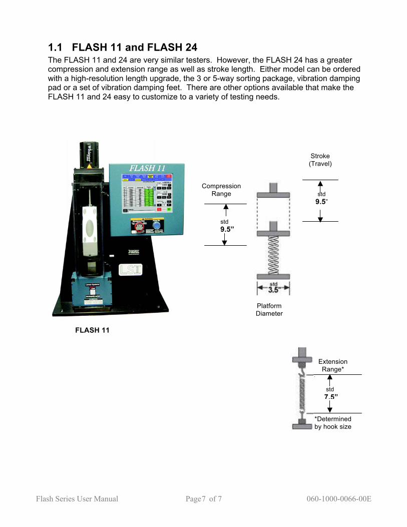
1.1 FLASH 11 and FLASH 24 The FLASH 11 and 24 are very similar testers. However, the FLASH 24 has a greater compression and extension range as well as stroke length. Either model can be ordered with a high-resolution length upgrade, the 3 or 5-way sorting package, vibration damping pad or a set of vibration damping feet. There are other options available that make the FLASH 11 and 24 easy to customize to a variety of testing needs.
FLASH 11
Extension Range*
Stroke (Travel)
Compression Range std
9.5”
std 9.5”
std 7.5”
*Determined by hook size
Platform Diameter

Flash Series User Manual Page of 8 060-1000-0066-00E 8
FLASH 11 and 24 with High Stiffness To accommodate testing high rate parts such as Belleville Washers or machined springs, a high stiffness feature can be ordered. Note that this feature restricts the normal stroke and range allowed. For example, the FLASH 11 with high stiffness has a modified range of 4.5 inches as opposed to 9.5 inches shown in the diagram in Section 1.2. The FLASH 24 with high stiffness has a modified range of 16.5 inches. Otherwise the corresponding testers are the same in size and operation.
FLASH 24
Platform Diameter
*Determined by hook size
Compression Range
Stroke (Travel)
Extension Range*
std 24”
std 22”
std 24”
Flash Series User Manual Page of 9 060-1000-0066-00E 9
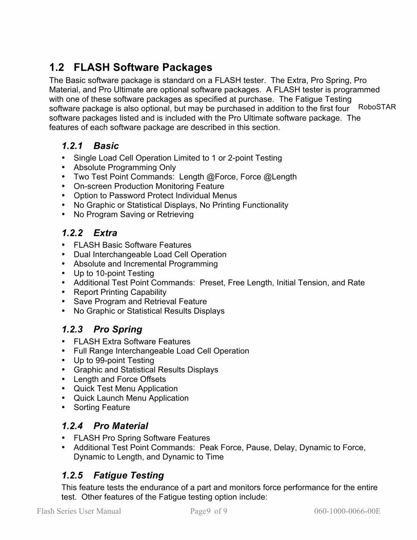
1.2 FLASH Software Packages The Basic software package is standard on a FLASH tester. The Extra, Pro Spring, Pro Material, and Pro Ultimate are optional software packages. A FLASH tester is programmed with one of these software packages as specified at purchase. The Fatigue Testing software package is also optional, but may be purchased in addition to the first four software packages listed and is included with the Pro Ultimate software package. The features of each software package are described in this section.
1.2.1 Basic • Single Load Cell Operation Limited to 1 or 2-point Testing • Absolute Programming Only • Two Test Point Commands: Length @Force, Force @Length • On-screen Production Monitoring Feature • Option to Password Protect Individual Menus • No Graphic or Statistical Displays, No Printing Functionality • No Program Saving or Retrieving
1.2.2 Extra • FLASH Basic Software Features • Dual Interchangeable Load Cell Operation • Absolute and Incremental Programming • Up to 10-point Testing • Additional Test Point Commands: Preset, Free Length, Initial Tension, and Rate • Report Printing Capability • Save Program and Retrieval Feature • No Graphic or Statistical Results Displays
1.2.3 Pro Spring • FLASH Extra Software Features • Full Range Interchangeable Load Cell Operation • Up to 99-point Testing • Graphic and Statistical Results Displays • Length and Force Offsets • Quick Test Menu Application • Quick Launch Menu Application • Sorting Feature
1.2.4 Pro Material • FLASH Pro Spring Software Features • Additional Test Point Commands: Peak Force, Pause, Delay, Dynamic to Force,
Dynamic to Length, and Dynamic to Time
1.2.5 Fatigue Testing This feature tests the endurance of a part and monitors force performance for the entire test. Other features of the Fatigue testing option include:
RoboSTAR
Flash Series User Manual Page of 10 060-1000-0066-00E 10
• Preset Cycles up to 10,000,000 • Archive Data During Cycling at Preset Intervals to a File Viewable via Intranet • Program Testing to Stop at Fatigue or Breakage Point
1.2.6 Pro Ultimate This FLASH software package is the highest end, full feature package available from LSI for automated parts testing. • FLASH Pro Spring Software Features • FLASH Pro Material Software Features • Additional Test Point Command: Fatigue • Fatigue Testing Software Package • Dynamic Testing option—real-time test by force/length • Test Preference—to absolute length or deflection from a point
1.3 Smart Interchangeable Load Cells All of the FLASH models can be purchased with interchangeable load cell capacity. This requires a minimum of the FLASH Extra software package which supports dual load cells or any of the FLASH Pro software packages allowing up to the maximum number of load cell capacities offered for a particular model. Changing out load cells on the FLASH Series testers is very easy and takes just a few minutes. See section 7.1 for instructions.
1.4 Whisper Servo Drive Available on FLASH Series 1,000, 2,000, and 3,000 lb testers, the Whisper Servo Drive is a closed loop servo drive that increases rapid travel speed by approximately 200% to a maximum of 3 inches per second. With this feature rapid speed can be maintained to full load. Expect dramatic test cycle time reductions, especially when testing at greater loads. As a bonus, testing noise is also reduced.
1.5 Web Service, Network, and Printer Connection These features are set up through the Access Operation System option located under FLASH Setup. The Operating System is password protected. See section 5.7.6 about gaining access. The web and network service will need to be set up by an IT Technician on the tester location end and coordinated with LSI to establish. Contact LSI for details.
1.6 Additional Options and Equipment • Inkjet Printer; connect to tester for reports, includes USB cable • Power Options; 240 VAC, 50 / 60 Hz; • Thru-Rod Accessory Package; used to test springs that tend to buckle during
compression • Sorting Packages; 3 or 5-way can be ordered with automation interface port • Twist Under Load – TUL; measures the amount of twist in any given spring • Platforms and Fixtures; larger platforms and various types of extension hooks are
available to suit a variety of testing needs • Fatigue Plate Assembly; used to perform endurance testing on multiple parts at the
same time

Flash Series User Manual Page of 11 060-1000-0066-00E 11
See www.larsonsystems.com for details about these and other options.
2 USING THIS MANUAL • Have the FLASH tester accessible while following along with this manual. • Be sure to read the Safety and Use Guidelines in section 3 before starting. • Instruction for basic operation begins at section 4 – Machine Setup. Familiarity with this
section will instill proper use of the interactive touch screen and make the more complex screens that follow easy to learn.
• Any instruction in brackets and bold type refers to a button on the screen. • Main menu applications are described in section 5 starting with the easiest. • Section 6 – Examples of Test Programs leads the operator through programming, saving a
program, running a test, and viewing results. Items learned in separate sections are put together in a usable sequence for a practical application.
• Know the specifics about the configuration of the FLASH, as some sections of this manual may not apply. Note the model of tester and level of software purchased to determine.
3 SAFETY AND USE GUIDELINES 3.1 Important Considerations • Compressed springs have stored potential energy proportional to the spring
constant. Use care and release this energy in a controlled manner to avoid injury. • Do not apply a force greater than the tester is designed for. • Be sure the operating area is clean and dry. • All parts to be tested should be free of oil and contaminants. • Keep the tester from contact with liquid. • This User Manual should be kept available for quick reference. • The protective enclosure should be kept closed during testing. • Use of protective eyewear is recommended for safety. • Follow all instructions and warnings associated with the use of the FLASH tester.
3.2 The Safety Shield Enclosure Each FLASH Tester is equipped with a fully enclosed testing area with safety interlock. This safety shield may be designed as a door or cover on the tester protecting the operator from injury if parts should fly out from the testing area as load is applied. DO NOT TAMPER WITH, REMOVE, OR MODIFY THE SAFETY SHIELD or the tester’s warranty shall be void.
3.3 Abort Test and Emergency Stop The red [Abort Test] button located in the lower right of the display is the first means of stopping platform movement instantly in an emergency situation. The red Emergency Stop button identified on the front of the FLASH Tester is also designed for use in an emergency, but not to be used frequently for shut down. For powering down under normal operating conditions, Windows must be properly exited first by touching the red [Shut Down] button in the upper right of the display screen. A prompt will appear to verify. Touch [Yes] to continue. A message says, “Windows is shutting down”. The screen will

Flash Series User Manual Page of 12 060-1000-0066-00E 12
display the Windows logo and the message, “It is now safe to turn off your computer.” The Emergency Stop button may now be pushed to turn off the tester. Using the Emergency Stop button by itself repeatedly for normal shutdown will likely result in OS data corruption. NOTE: A FLASH tester, such as a RoboSTAR used with an ASSP system may not have an Emergency Stop button. Follow instructions for the ASSP.
3.4 Windows 7 Automatic Logon By default, the FLASH Series of testers are programmed to bypass the MS Windows 7 logon prompt at startup to automatically login anyone to operate the tester. This is a more convenient setting for its use. Depending on your network administrator policy, using the automatic login may be considered a security risk if the tester has been connected to your company’s network. The Windows logon bypass could allow anyone using the tester to also have access to that network, authorized or not. The user account on the FLASH tester does not have the necessary write privileges. The Windows login was originally bypassed at the LSI factory using an Administrator account. Once this feature is turned off, a Windows login prompt will appear when the tester is turned on. Contact Larson Systems if assistance is needed with this feature. How the Windows 7 Login is used when automatic login is turned off: The prompt will say “FLASH User” in the first dialog box and ask for a password in the next box. Touch the dialog box to access the on-screen keyboard, touch the letters on the keyboard to type password, touch [Enter] when finished, then touch [OK].
4 MACHINE SETUP Place the tester on a level and stable work area where the user can test parts in a comfortable manner. The FLASH tester should be positioned to allow ease in loading, testing and removing parts from the testing area. The operator should also be able to easily view and access the display. Touch the screen with a finger to use the touch-screen interface.
4.1 On and Off Procedure Turning on the tester is the first step to getting started: 1. Turn the red Emergency Stop button on the outside of the tester clockwise. The knob
pops out to allow the tester to receive power. 2. Next, push the blue Power On button to start up. The Windows XP Operating System
is loaded first and then the FLASH software if the automatic logon feature is turned on. See section 3.4 regarding this feature.
3. When the automatic logon feature is turned off a dialog box appears with “FLASH User” in the first box and a blank box for password entry below. Touch the dialog box to access the on-screen keyboard, letters on the keyboard to type password, touch [Enter] when finished, and then touch [OK]. The password is managed by Supervisor access.
4. The FLASH testing software is now loading. The screen shown below appears next. The display defaults to the Manual Mode (highlighted in yellow) in compression testing (indicated in the force display).
Flash Series User Manual Page of 13 060-1000-0066-00E 13
The proper procedure for turning off the tester is extremely important: 1. Touch the red [Shut Down] button located in the upper right of the display when ready
to turn of the machine. 2. Windows will close and a prompt will appear when it is safe to turn off your computer.
Push the red Emergency Stop button to turn power off. Both steps must be followed for normal operating shut down. Using just the Emergency Stop button for this purpose will likely corrupt Operating System data.
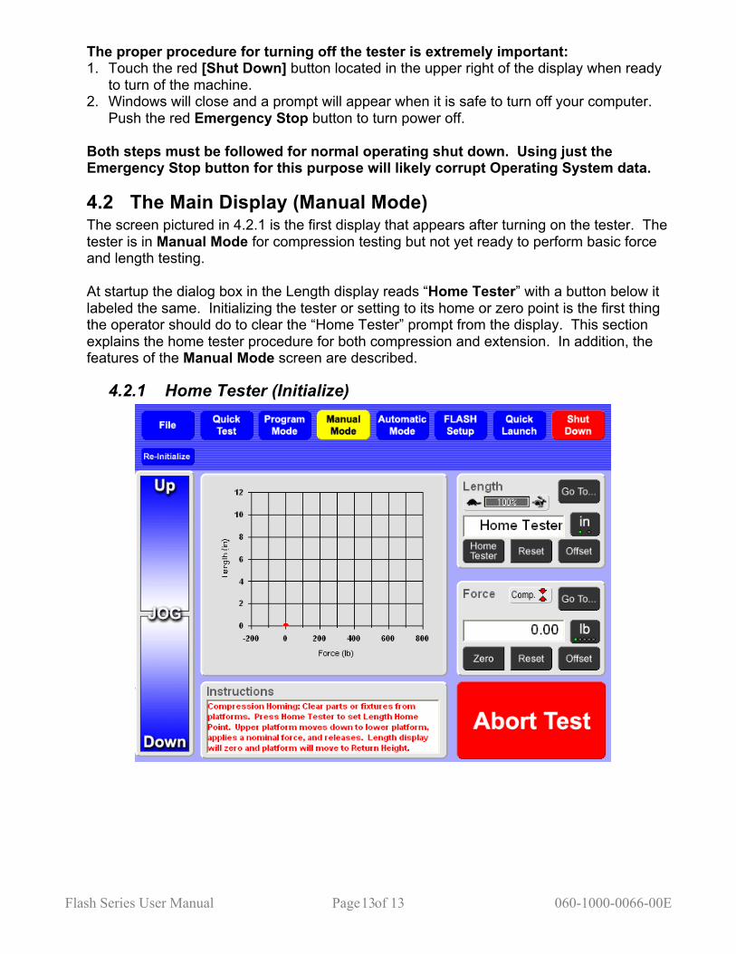
4.2 The Main Display (Manual Mode) The screen pictured in 4.2.1 is the first display that appears after turning on the tester. The tester is in Manual Mode for compression testing but not yet ready to perform basic force and length testing. At startup the dialog box in the Length display reads “Home Tester” with a button below it labeled the same. Initializing the tester or setting to its home or zero point is the first thing the operator should do to clear the “Home Tester” prompt from the display. This section explains the home tester procedure for both compression and extension. In addition, the features of the Manual Mode screen are described.
4.2.1 Home Tester (Initialize)
Flash Series User Manual Page of 14 060-1000-0066-00E 14
Set Length Home Point For Compression: 1. Make sure the testing area between the upper and lower platform is clear of any
parts, materials, or fixtures. Close the safety shield. 2. Touch [Home Tester] on the left below the dialog box in the Length display. This
initiates the automatic and slow downward movement of the upper platform to meet the lower platform. The Instructions box reads “Tester Initializing”.
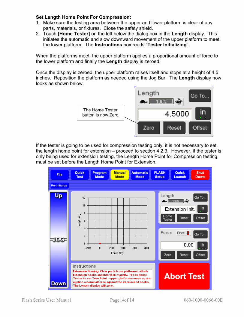
When the platforms meet, the upper platform applies a proportional amount of force to the lower platform and finally the Length display is zeroed. Once the display is zeroed, the upper platform raises itself and stops at a height of 4.5 inches. Reposition the platform as needed using the Jog Bar. The Length display now looks as shown below.
If the tester is going to be used for compression testing only, it is not necessary to set the length home point for extension – proceed to section 4.2.3. However, if the tester is only being used for extension testing, the Length Home Point for Compression testing must be set before the Length Home Point for Extension.
The Home Tester button is now Zero
Flash Series User Manual Page of 15 060-1000-0066-00E 15
Set Length Home Point for Extension: When setting the Length Home Point for extension, the compression setting will need to be changed to extension. Touch the [Comp.] indicator in the Force display. (See section 4.2.2 about changing Compression and Extension testing.) The dialog box in the Length display will read “Extension Init.” as shown above. 1. Make sure the testing area is clear of any parts or objects and install extension
hooks* certified to the capacity of the tester. 2. Use the Jog Bar to adjust the upper platform so the extension hooks interlock. 3. Touch [Home Tester] to initialize for extension testing. *When other fixtures are used, the automatic extension initialization feature can be disabled to allow setting a zero point manually. This is controlled under FLASH Setup in the User settings. During Automated Initialization: The upper platform moves up and applies a force of about 10% full scale. The upper platform stays at the force applied and the Length display is zeroed. As in the compression procedure, the [Home Tester] button is now [Zero]. The hooks will need to be released by moving the upper platform using the Jog Bar in Manual Mode. Once the Length Home Point has been set, it does not need to be done again until the next startup. If [Zero] is touched in the Length display as an adjustment for a particular situation or unintentionally with the platforms apart, touch [Reset] to make the original initialization point zero again. In addition, the [Re-Initialize] button located just below the [File] menu button may be used to initialize the tester without turning off the machine and starting over.
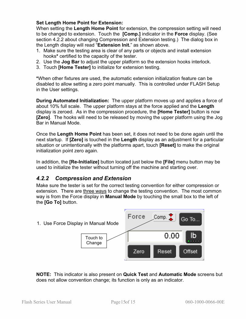
4.2.2 Compression and Extension Make sure the tester is set for the correct testing convention for either compression or extension. There are three ways to change the testing convention. The most common way is from the Force display in Manual Mode by touching the small box to the left of the [Go To] button. NOTE: This indicator is also present on Quick Test and Automatic Mode screens but does not allow convention change; its function is only as an indicator.
Touch to Change
1. Use Force Display in Manual Mode

Flash Series User Manual Page of 16 060-1000-0066-00E 16
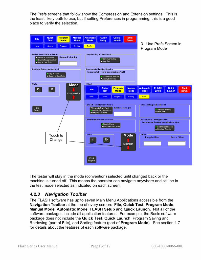
When the convention is changed, the background of the screen will change color from light blue for compression (default setting) to dark blue for extension. Touch this button to toggle between and recognizes the difference. This difference is a visual reminder for the user if using compression and extension testing or more than one person uses the tester. The convention can also be changed in the Program Mode as shown in the screen below. In addition, there is a button to change the setting in [Prefs] under the Program Mode.
In the black box listing Compression and Extension, touch the box to change testing conventions. The box in front of Compression and Extension will change color. The green box will be in front of the active convention. In addition, the background screen color will change. Another way to change the testing convention is also in the Program Mode but from the Prefs menu.
Touch to Change
2. Use Button in Program Mode
Flash Series User Manual Page of 17 060-1000-0066-00E 17
The Prefs screens that follow show the Compression and Extension settings. This is the least likely path to use, but if setting Preferences in programming, this is a good place to verify the selection.
The tester will stay in the mode (convention) selected until changed back or the machine is turned off. This means the operator can navigate anywhere and still be in the test mode selected as indicated on each screen.
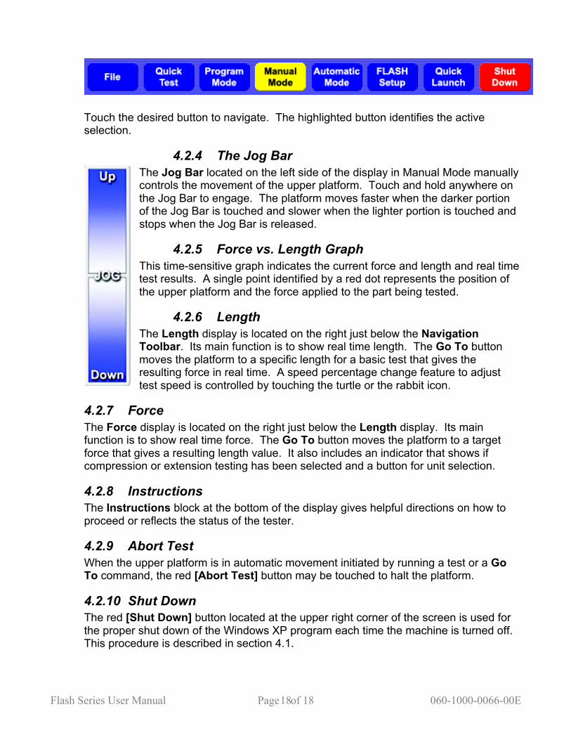
4.2.3 Navigation Toolbar The FLASH software has up to seven Main Menu Applications accessible from the Navigation Toolbar at the top of every screen: File, Quick Test, Program Mode, Manual Mode, Automatic Mode, FLASH Setup and Quick Launch. Not all of the software packages include all application features. For example, the Basic software package does not include the Quick Test, Quick Launch, Program Saving and Retrieving (part of File), and Sorting feature (part of Program Mode). See section 1.7 for details about the features of each software package.
Touch to Change
3. Use Prefs Screen in Program Mode
Flash Series User Manual Page of 18 060-1000-0066-00E 18
Touch the desired button to navigate. The highlighted button identifies the active selection.
4.2.4 The Jog Bar The Jog Bar located on the left side of the display in Manual Mode manually controls the movement of the upper platform. Touch and hold anywhere on the Jog Bar to engage. The platform moves faster when the darker portion of the Jog Bar is touched and slower when the lighter portion is touched and stops when the Jog Bar is released.
4.2.5 Force vs. Length Graph This time-sensitive graph indicates the current force and length and real time test results. A single point identified by a red dot represents the position of the upper platform and the force applied to the part being tested.
4.2.6 Length The Length display is located on the right just below the Navigation Toolbar. Its main function is to show real time length. The Go To button moves the platform to a specific length for a basic test that gives the resulting force in real time. A speed percentage change feature to adjust test speed is controlled by touching the turtle or the rabbit icon.
4.2.7 Force The Force display is located on the right just below the Length display. Its main function is to show real time force. The Go To button moves the platform to a target force that gives a resulting length value. It also includes an indicator that shows if compression or extension testing has been selected and a button for unit selection.
4.2.8 Instructions The Instructions block at the bottom of the display gives helpful directions on how to proceed or reflects the status of the tester.
4.2.9 Abort Test When the upper platform is in automatic movement initiated by running a test or a Go To command, the red [Abort Test] button may be touched to halt the platform.
4.2.10 Shut Down The red [Shut Down] button located at the upper right corner of the screen is used for the proper shut down of the Windows XP program each time the machine is turned off. This procedure is described in section 4.1.

Flash Series User Manual Page of 19 060-1000-0066-00E 19
4.2.11 Re-Initialize The [Re-Initialize] button located below the [File] menu button is used to initialize the tester to its Home Length Point without turning off the machine and starting again. See the end of section 4.2.1 about this function.
5 MAIN MENU APPLICATIONS There are seven Main Menu Applications that may be accessed from the Navigation Toolbar at the top of the display: • File – Clear all current specifications and result data, open a file from storage to run a test
or view results, save a programmed test, or rename a file. • Quick Test – Run a generic test on an unknown part and create a test to run on similar
parts based on the characteristics found during the quick test. • Program Mode – Create and customize a variety of test applications that may be saved
and used as needed. No need to create a test each time the FLASH tester is used for a different application.
• Manual Mode – Control the platform movement manually, use a “go to” function for force and length testing and view results.
• Automatic Mode – Run test applications repetitively and generate results in various formats to be shared or printed in hard copy.
• FLASH Setup – Enter basic fixed information and preferences. The User and Print Setup submenus contain default specifications set at the factory. Review these before testing and make changes if needed. Especially important if running a unique test application.
• Quick Launch – Select and run a pre-defined test application. The use of each menu item listed is described in this section. Note that the menu items do not appear in the order listed above or on the Navigation Toolbar. The menu features are usually used in conjunction with each other. For example: after creating a test sequence in the Program Mode the user may go to Automatic Mode to run the test, then save the information gathered using File.
Flash Series User Manual Page of 20 060-1000-0066-00E 20
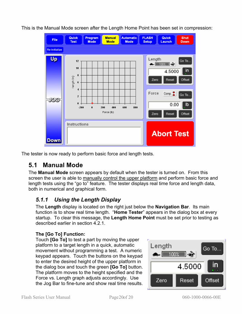
This is the Manual Mode screen after the Length Home Point has been set in compression: The tester is now ready to perform basic force and length tests.
5.1 Manual Mode The Manual Mode screen appears by default when the tester is turned on. From this screen the user is able to manually control the upper platform and perform basic force and length tests using the “go to” feature. The tester displays real time force and length data, both in numerical and graphical form.
5.1.1 Using the Length Display The Length display is located on the right just below the Navigation Bar. Its main function is to show real time length. “Home Tester” appears in the dialog box at every startup. To clear this message, the Length Home Point must be set prior to testing as described earlier in section 4.2.1. The [Go To] Function: Touch [Go To] to test a part by moving the upper platform to a target length in a quick, automatic movement without programming a test. A numeric keypad appears. Touch the buttons on the keypad to enter the desired height of the upper platform in the dialog box and touch the green [Go To] button. The platform moves to the height specified and the Force vs. Length graph adjusts accordingly. Use the Jog Bar to fine-tune and show real time results.
Flash Series User Manual Page of 21 060-1000-0066-00E 21
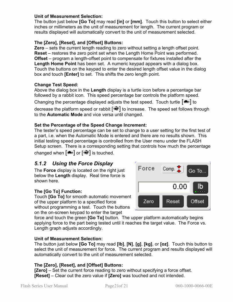
Unit of Measurement Selection: The button just below [Go To] may read [in] or [mm]. Touch this button to select either inches or millimeters as the unit of measurement for length. The current program or results displayed will automatically convert to the unit of measurement selected. The [Zero], [Reset], and [Offset] Buttons: Zero – sets the current length reading to zero without setting a length offset point. Reset – restores the zero point set when the Length Home Point was performed. Offset – program a length-offset point to compensate for fixtures installed after the Length Home Point has been set. A numeric keypad appears with a dialog box. Touch the buttons on the keypad to enter the desired length offset value in the dialog box and touch [Enter] to set. This shifts the zero length point. Change Test Speed: Above the dialog box in the Length display is a turtle icon before a percentage bar followed by a rabbit icon. This speed percentage bar controls the platform speed. Changing the percentage displayed adjusts the test speed. Touch turtle [ ] to decrease the platform speed or rabbit [ ] to increase. The speed set follows through to the Automatic Mode and vice versa until changed. Set the Percentage of the Speed Change Increment: The tester’s speed percentage can be set to change to a user setting for the first test of a part, i.e. when the Automatic Mode is entered and there are no results shown. This initial testing speed percentage is controlled from the User menu under the FLASH Setup screen. There is a corresponding setting that controls how much the percentage changed when [ ] or [ ] is touched.
5.1.2 Using the Force Display The Force display is located on the right just below the Length display. Real time force is shown here. The [Go To] Function: Touch [Go To] for smooth automatic movement of the upper platform to a specified force without programming a test. Touch the buttons on the on-screen keypad to enter the target force and touch the green [Go To] button. The upper platform automatically begins applying force to the part being tested until it reaches the target value. The Force vs. Length graph adjusts accordingly. Unit of Measurement Selection: The button just below [Go To] may read [lb], [N], [g], [kg], or [oz]. Touch this button to select the unit of measurement for force. The current program and results displayed will automatically convert to the unit of measurement selected. The [Zero], [Reset], and [Offset] Buttons: [Zero] – Set the current force reading to zero without specifying a force offset. [Reset] – Clear out the zero value if [Zero] was touched and not intended.

Flash Series User Manual Page of 22 060-1000-0066-00E 22
[Offset] – Enter a force-offset value to compensate for the weight of fixtures installed prior to testing. A numeric keypad appears with a dialog box when the [Offset] button is touched. Touch the buttons on the keypad to enter the desired force offset value and touch [Enter] to set. This adjusts the zero force starting point.
5.1.3 Run A Basic Test The Length Home Point should have been set at startup as described in section 5.1.1. Setup of Tester: 1. Raise the upper platform using the Jog Bar to a height greater than the part being
tested within the tester’s maximum range. 2. Open the enclosure and place the part being tested on the platform. Make sure the
item is centered on the lower platform. Close and secure the enclosure. Perform either Force @ Length or Length @ Force described next. Force @ Length: 1. Touch [Zero] in the Force display to eliminate the part weight from the force reading. 2. Touch [Go To] in the Length display. Enter the length on the keypad that the upper
platform should go to for force measurement and touch the green [Go To] button. The platform immediately moves to the specified length and takes a measurement that appears in the Force display. This Force @ Length measurement is also reflected on the graph by the position of the red dot. The platform will remain at this height until a new command is given or moved manually using the Jog Bar. Length @ Force: 1. Touch [Zero] in the Force display to eliminate the part weight from the force reading. 2. Touch [Go To] in the Force display. Enter the force on the keypad that the upper
platform should apply and touch the green [Go To] button. The platform slowly applies force to the part and reduces speed as is reaches its destination force. The length appears in the dialog box of the Length display and the position of the red dot on the graph adjusts accordingly. Again, the platform will remain at this height until a new command is given or moved manually using the Jog Bar. In either scenario, the [Go To] command may be changed to a new specified force or length as many times as the user would like. Adjustments to length can be made using the Jog Bar to fine-tune a measurement. In addition, the units of measurement or speed of testing may be changed.
5.2 Program Mode Password Protection Optional Touch [Program Mode] on the Navigation Toolbar to start. Use the Program Mode to create a variety of customized testing sequences, set test preferences and define sorting criteria. There are five sub-screens in the Program Mode: New, Check, Program, Sorting, and Preferences (Prefs). Note: The Sorting sub-screen feature is not available with the Basic or Extra software packages. See section 1.7.1 for additional information about the software packages.

Flash Series User Manual Page of 23 060-1000-0066-00E 23
5.2.1 New Touch [New] to clear all specifications and results. A message will appear to verify the action. Touch [Yes] to clear and continue or [No] to cancel the action. Any test points, preferences, and sorting criteria that have been entered will be cleared if [Yes] is selected. This includes any results that were obtained.
5.2.2 Check Touch [Check] to check for any errors when creating a test point sequence. If the sequence contains any errors, a message box will appear and identify the problem. Touch [OK] to exit the message box. The Test Point screen moves to the test point that contains the error. Make the correction and check the sequence again when satisfied. The message box will indicate when the sequence is good and contains no errors. Touch [OK] to clear the message box and continue.
5.2.3 Program When [Program Mode] is selected the display defaults to the [Program] sub-screen shown below. The selections are highlighted in yellow. This is where a test application sequence can be defined and programmed.
5.2.3.1 Using the Test Point Box This screen always displays a gray box in its center that may be titled “End of Test” (shown), “Command:”, or show available command buttons. Above this gray box and to the left is a smaller gray box titled “Test Point”. Scroll through the available test points by touching the
Flash Series User Manual Page of 24 060-1000-0066-00E 24
arrow keys, [◄] or [►]. The number of test points available for a sequence varies by the software package purchased (see section 1.7.1 for more information). To go to a specific test point, touch the value dialog box and enter the desired test point number using the keypad that is displayed. As the arrow [►] is touched from test point 1, if each test point displays the “End Of Test” box, no commands have been entered for a test sequence yet. To create a new Test Point sequence begin at Test Point 1. The Test Point box is inactive when the larger gray box displays the test point command buttons. From the Test Point box, test points may be inserted or deleted as a test point application sequence is created. Instructions for using [Insert] and [Delete] are found in section 5.2.3.6 – Creating a Test Point Application Sequence.
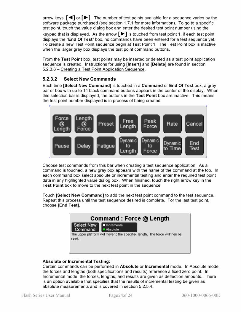
5.2.3.2 Select New Commands Each time [Select New Command] is touched in a Command or End Of Test box, a gray bar or box with up to 14 black command buttons appears in the center of the display. When this selection bar is displayed, the buttons in the Test Point box are inactive. This means the test point number displayed is in process of being created.
Choose test commands from this bar when creating a test sequence application. As a command is touched, a new gray box appears with the name of the command at the top. In each command box select absolute or incremental testing and enter the required test point data in any highlighted value dialog box. When finished, touch the right arrow key in the Test Point box to move to the next test point in the sequence. Touch [Select New Command] to add the next test point command to the test sequence. Repeat this process until the test sequence desired is complete. For the last test point, choose [End Test].
Absolute or Incremental Testing: Certain commands can be performed in Absolute or Incremental mode. In Absolute mode, the forces and lengths (both specifications and results) reference a fixed zero point. In Incremental mode, the forces, lengths, and results are given as deflection amounts. There is an option available that specifies that the results of incremental testing be given as absolute measurements and is covered in section 5.2.5.4.
Flash Series User Manual Page of 25 060-1000-0066-00E 25
Test Commands: The subsections that follow describe each possible command for the FLASH. Numerical data must be entered for many of the commands before moving to the next test point. However, some commands may not require any values, but will allow the user to enter optional data if desired. Text boxes that require data are labeled and highlighted. Optional text boxes for data are labeled, but not highlighted. Enter data by touching a text box to activate an on-screen keypad. Results from entering a nominal value calculate a percentage representing the distance of the measurement taken from that nominal value. Some tests allow an optional tolerance value to be entered. Tolerance is entered as a percentage from 0.01% to 99.99% or as a specific upper or lower limit (USL or LSL). Either way the tolerance is entered, the other method is automatically calculated and filled when results are displayed. For example, if a tolerance percentage is entered, the USL and LSL are automatically calculated. The test point is “conditional” when using a tolerance value to obtain test data. A command may allow entering a value to specify the test point to be performed at a different speed than other test points. The value entered represents the maximum speed the upper platform is allowed to reach during the test. All platform motion starts at a slow speed and gradually increases to its maximum speed. Depending on the distance from the platform to the test point target, the maximum speed allowed (by default or as specified) may not always be reached. If this option is left blank the default speed will be used which allows a maximum movement of 180 inches per minute.
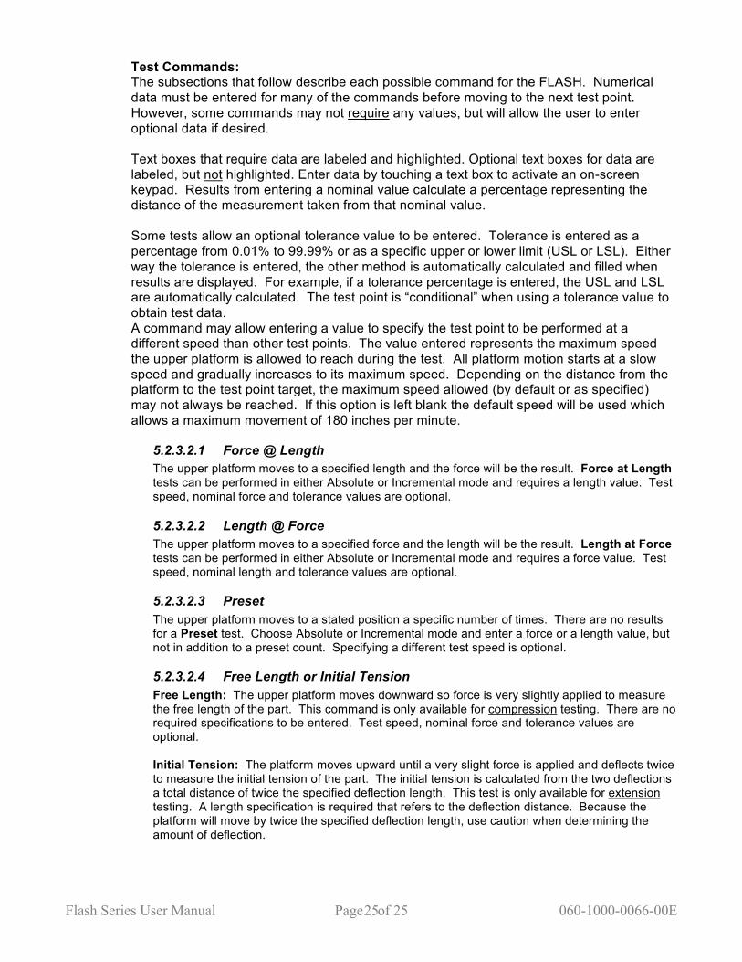
5.2.3.2.1 Force @ Length The upper platform moves to a specified length and the force will be the result. Force at Length tests can be performed in either Absolute or Incremental mode and requires a length value. Test speed, nominal force and tolerance values are optional.
5.2.3.2.2 Length @ Force The upper platform moves to a specified force and the length will be the result. Length at Force tests can be performed in either Absolute or Incremental mode and requires a force value. Test speed, nominal length and tolerance values are optional.
5.2.3.2.3 Preset The upper platform moves to a stated position a specific number of times. There are no results for a Preset test. Choose Absolute or Incremental mode and enter a force or a length value, but not in addition to a preset count. Specifying a different test speed is optional.
5.2.3.2.4 Free Length or Initial Tension Free Length: The upper platform moves downward so force is very slightly applied to measure the free length of the part. This command is only available for compression testing. There are no required specifications to be entered. Test speed, nominal force and tolerance values are optional. Initial Tension: The platform moves upward until a very slight force is applied and deflects twice to measure the initial tension of the part. The initial tension is calculated from the two deflections a total distance of twice the specified deflection length. This test is only available for extension testing. A length specification is required that refers to the deflection distance. Because the platform will move by twice the specified deflection length, use caution when determining the amount of deflection.
Flash Series User Manual Page of 26 060-1000-0066-00E 26
5.2.3.2.5 Peak Force The upper platform moves to a specified length and the maximum force encountered is the result. A target length is required. Nominal force and tolerance values are optional. The test speed defaults to 15 inches per minute when measuring Peak Force and can be changed.
5.2.3.2.6 Rate The rate is calculated between two test points. Rate is defined as the difference between two test points divided by the distance between. Two test points are required in the sequence before Rate is selected. These two test points are required data so the Rate is calculated based on the correct test points. Nominal rate and tolerance values are optional.
5.2.3.2.7 Cancel Cancel will reverse the screen displayed to its previous setting.
5.2.3.2.8 Pause The test sequence stops until manually resumed by the operator. To use this command, touch [Pause], then touch the right arrow to move to the next test point, then touch [Select New Command] to choose the next command that will be performed when the test is resumed. When a Pause test point is reached during a test sequence, testing stops. The [Resume] button is now active. Touch [Resume] when ready to continue testing.
5.2.3.2.9 Delay The test sequence stops for a specified amount of time and then resumes testing automatically when the time specified expires. To use this command, touch [Delay] and enter the amount of time delay desired. Be sure this command is placed correctly in the test command sequence. Touch the right arrow to move to the next test point, then touch [Select New Command] to choose the next command at which testing will resume.
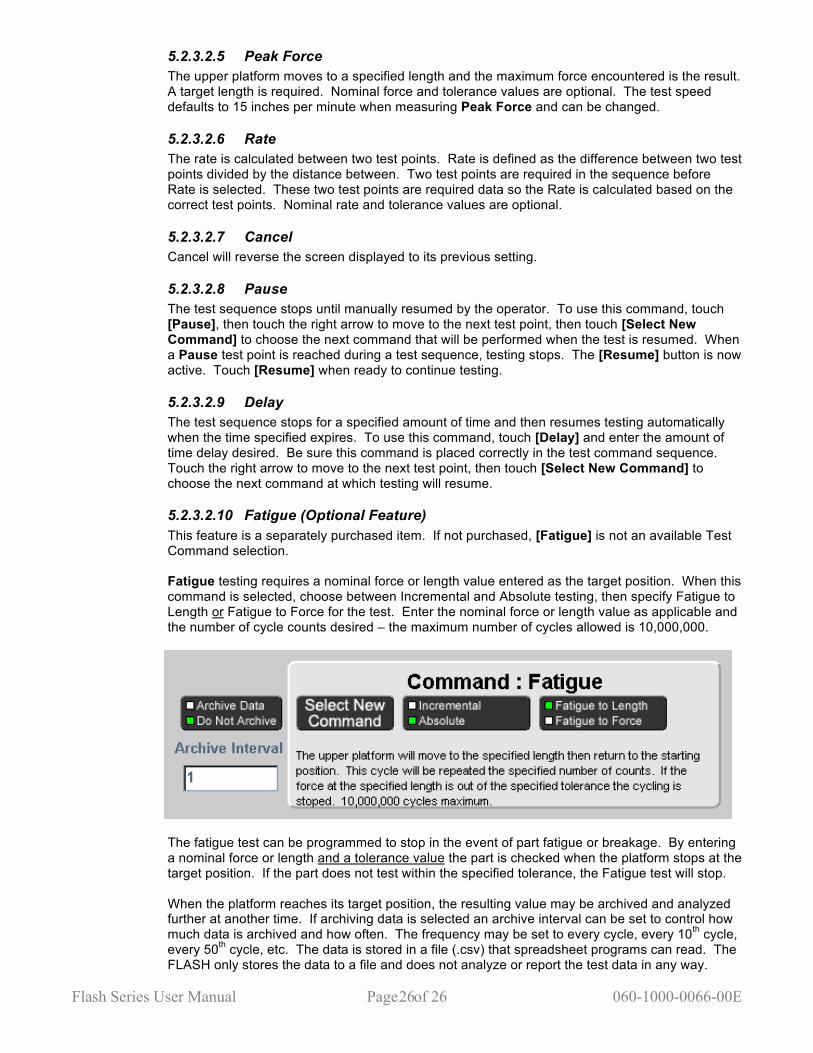
5.2.3.2.10 Fatigue (Optional Feature) This feature is a separately purchased item. If not purchased, [Fatigue] is not an available Test Command selection. Fatigue testing requires a nominal force or length value entered as the target position. When this command is selected, choose between Incremental and Absolute testing, then specify Fatigue to Length or Fatigue to Force for the test. Enter the nominal force or length value as applicable and the number of cycle counts desired – the maximum number of cycles allowed is 10,000,000.
The fatigue test can be programmed to stop in the event of part fatigue or breakage. By entering a nominal force or length and a tolerance value the part is checked when the platform stops at the target position. If the part does not test within the specified tolerance, the Fatigue test will stop. When the platform reaches its target position, the resulting value may be archived and analyzed further at another time. If archiving data is selected an archive interval can be set to control how much data is archived and how often. The frequency may be set to every cycle, every 10th cycle, every 50th cycle, etc. The data is stored in a file (.csv) that spreadsheet programs can read. The FLASH only stores the data to a file and does not analyze or report the test data in any way.
Flash Series User Manual Page of 27 060-1000-0066-00E 27
A Fatigue Plate Assembly is available for purchase for testing up to eight springs or parts at the same time. Parts stay in place with special knobs and can be diameters of 3/4", 1/2", or 1/4". Details about this product and using fatigue testing can be found on the LSI website at www.larsonsystems.com.
5.2.3.2.11 Dynamic Testing Dynamic Testing is available with Pro Material or Pro Ultimate software. It allows you to test and record real-time results, change the increments, and automatically re-graph the results.
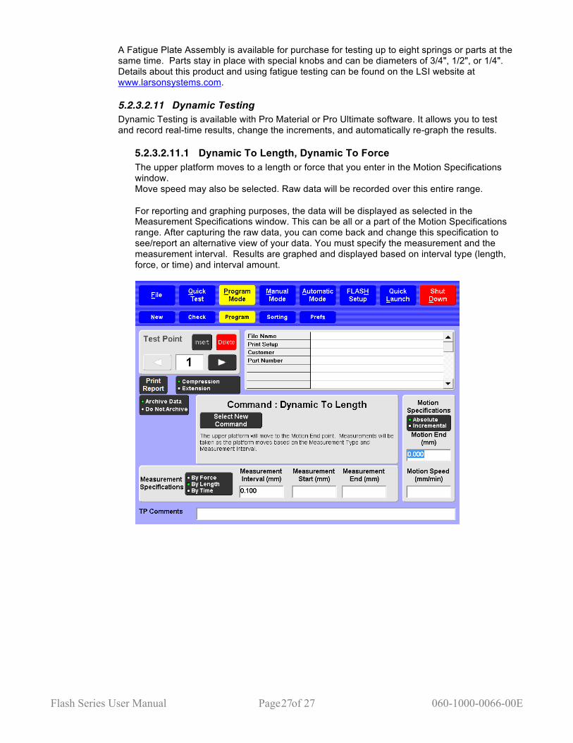
5.2.3.2.11.1 Dynamic To Length, Dynamic To Force The upper platform moves to a length or force that you enter in the Motion Specifications window. Move speed may also be selected. Raw data will be recorded over this entire range. For reporting and graphing purposes, the data will be displayed as selected in the Measurement Specifications window. This can be all or a part of the Motion Specifications range. After capturing the raw data, you can come back and change this specification to see/report an alternative view of your data. You must specify the measurement and the measurement interval. Results are graphed and displayed based on interval type (length, force, or time) and interval amount.

Flash Series User Manual Page of 28 060-1000-0066-00E 28
5.2.3.2.12 Dynamic To Time The upper platform remains in position for a specified amount of time. Readings are taken at specified time intervals until the target time specified has expired. This type of testing is most commonly used in material testing or when determining if length or force is maintained over a nominal time. In any of the “Dynamic To” Test Point Commands, you may change the Interval type in the box titled Measurement Specifications by touching the selection. You may enter a starting and an ending point for interval measurement or specify a different test speed, if desired.
Flash Series User Manual Page of 29 060-1000-0066-00E 29
5.2.3.2.13 Dynamic to Deflection Dynamic to deflection allows you to test deflection on suspension springs, Belleville washers and switches and buttons that require downward pressure to operate. This test procedure allows you to create a zero point for the test part. This point can be a test return point or a point determined by a program command. The upper platform then moves to a specified length or force. Readings are taken at specified intervals as the platform moves to the target point. Results are then displayed as force to deflection or rate to deflection.
5.2.3.2.14 Dynamic Rate Averaging When the Test Graph Force vs. Rate or Length vs. Rate is shown, the rate values can be averaged to show a smoother curve. A value of 1 represents no averaging, showing a rate between two adjunct digital points. A value of 100 is maximum averaging. Dynamic to Deflection and Dynamic Rate Averaging can be selected when you set your test preferences in the Automatic Mode (Section 11.5.4).
5.2.3.2.15 End Test This command specifies the end of the test. When a test is in progress, the first instance of this command will end the test, even if there are valid commands after the End Of Test command.
5.2.3.3 Customer / Part Number For each test created, a Customer name and Part Number can be entered to appear on the printed report. Touch the text box to enter. In addition, when a stored program is retrieved, the retrieved file name would be on the printed report and also appear on the display just below File. If the test program has not yet been saved and a Part Number is entered, the Part Number defaults as the filename unless manually changed.
5.2.3.4 TP Comments Each individual test point can contain comments that appear on the printed report. Enter test point comments by touching the text box at the bottom of the display. If creating a test point sequence by selecting the test point commands, each test point will already be labeled as the test point command on the printed report under test specifications. Any comment entered will appear below the labeled test point. To view how this looks in a printed report, see Preview in section 5.2.3.5.
5.2.3.5 Print Report This button will generate a hard copy of the program and any results gathered. When [Print Report] is touched, a message box to confirm appears. The options are to Print, Preview, or Cancel. The Preview function can be used even if a printer is not connected to the tester. Viewing what the printed report would look like may be helpful to determine relevance of results, the best viewing format, if the printout needs to be modified, etc. Results can be saved and printed or viewed in the format desired at a later time. Report printout specifications may also be modified in FLASH Setup > Print Setup. When viewing a report in Preview:
• Scroll through the pages using arrows along the side or bottom of page • Use [Zoom] to zoom in or out to view by page or enlarge • Touch [Close Preview] to exit Preview
5.2.3.6 Creating a Test Point Application Sequence Before creating a test point application sequence go to [Prefs] to view the default settings and make any necessary changes. (See section 5.2.5). Touch [Program] to return. The End Of Test box should be displayed and the Test Point value box should be at 1.
Flash Series User Manual Page of 30 060-1000-0066-00E 30
1. Touch [Select New Command] in the End Of Test box. The Test Command selection bar appears:
2. Touch the desired Test Command. A box appears titled with the command selected. (Ex/ Command : Force @ Length)
3. In the command box choose Incremental or Absolute measurement. Choice is identified by a small green square. The box includes a description of what the machine does with this command. There may also be value boxes on the screen waiting for data to be entered.
4. To enter required data, touch the value box and a keypad will appear. Touch the desired numbers. When finished, touch [Enter].
5. TP Comments may be entered that will appear on the printed report. Touch the TP Comment dialog box at the bottom of the screen and an alphanumeric keypad appears. Type in a comment by touching the letters on the keypad.
6. When finished or if no data is required, touch the right arrow button in the Test Point box to move to the next Test Point. The End Of Test box appears.
7. To add more Test Point commands, repeat from step 1. 8. When the last Test Point command has been entered and the End Of Test box is
displayed the test application sequence is complete. 9. Touch [Check] to check for test point errors. During the course of programming the test points may be modified or changed using [Insert] or [Delete] as shown in the Test Point box.
5.2.3.6.1 Insert a Test Point First, a command box must be displayed to use the Test Point box. Navigate using the right or left arrow to view the test point in a sequence where a new test point will be inserted. The test point being viewed will move ahead one point to follow the inserted test point. 1. Touch [Insert] when viewing the test point. 2. Any test points already set at and above this point will shift up one. 3. The current test point is left blank and ready for a new test command. 4. Touch [Select New Command] to continue. 5. Choose the desired command from the Test Command selection bar to insert. 6. Enter any required or optional data, including TP Comments. 7. Navigate as needed to make changes to the test application sequence or go to the End of
Test, Check and continue.
5.2.3.6.2 Delete a Test Point Touch [Delete] to delete the test point being viewed. Any test points above the one deleted shift down by one in the sequence.
The Test Application created can now be run in [Automatic Mode], saved under [File], modified or cleared. The test sequence being used goes from mode to mode as the screens are navigated. A new test cannot be created or retrieved until the current test is cleared. To clear a test and results, touch [New] in Program Mode. A message to verify this action appears. (This does not delete saved programs.) These features allow easily customizing the data measured during a test sequence and positioning the order of the commands as needed.
5.2.4 Sorting Sorting is not available with the Basic and Extra software packages. See section 1.7. This section describes the items displayed on this screen and their use. Practical application examples follow for setting up a condition and output table for sorting.
Flash Series User Manual Page of 31 060-1000-0066-00E 31
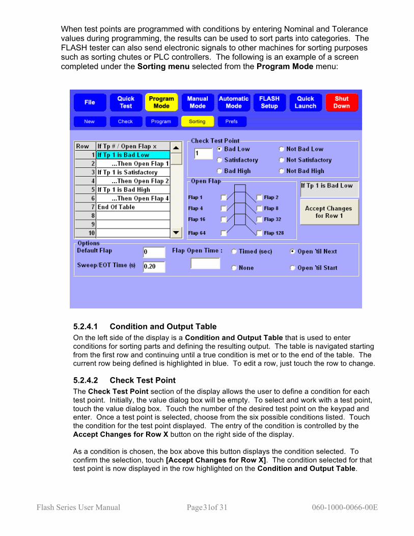
When test points are programmed with conditions by entering Nominal and Tolerance values during programming, the results can be used to sort parts into categories. The FLASH tester can also send electronic signals to other machines for sorting purposes such as sorting chutes or PLC controllers. The following is an example of a screen completed under the Sorting menu selected from the Program Mode menu:
5.2.4.1 Condition and Output Table On the left side of the display is a Condition and Output Table that is used to enter conditions for sorting parts and defining the resulting output. The table is navigated starting from the first row and continuing until a true condition is met or to the end of the table. The current row being defined is highlighted in blue. To edit a row, just touch the row to change.
5.2.4.2 Check Test Point The Check Test Point section of the display allows the user to define a condition for each test point. Initially, the value dialog box will be empty. To select and work with a test point, touch the value dialog box. Touch the number of the desired test point on the keypad and enter. Once a test point is selected, choose from the six possible conditions listed. Touch the condition for the test point displayed. The entry of the condition is controlled by the Accept Changes for Row X button on the right side of the display. As a condition is chosen, the box above this button displays the condition selected. To confirm the selection, touch [Accept Changes for Row X]. The condition selected for that test point is now displayed in the row highlighted on the Condition and Output Table.

Flash Series User Manual Page of 32 060-1000-0066-00E 32
5.2.4.3 Open Flap The Open Flap section of the display allows the selection of an output flap for a test point condition. Touch a flap selection from those listed to represent the category of a condition for sorting. An electronic signal is sent to a sorting device for the flap selected. As an output is selected for a test point condition, the box above the Accept Changes for Row X button reflects the output selected. To confirm the selection, touch [Accept Changes for Row X]. The output is displayed in the current row of the Condition and Output Table.
5.2.4.4 Options This section of the display contains three options to be set for sorting purposes: Default Flap, Sweep / EOT Time (s), and Flap Open Time.
5.2.4.4.1 Default Flap If the sorting table is traversed during a test point sequence and no true statement is found, a flap may be set to activate as a default mechanism. The Default Flap setting is Flap 0, resulting in no flaps being activated. Otherwise, touch the value dialog box to enter a preferred default flap selection.
5.2.4.4.2 Sweep / EOT Time (s) After the last output signal is sent during an individual test sequence on a specific part and the sorting flap is determined, the upper platform moves to its ending position generating a signal that represents the End of Test (EOT). The EOT signal can be connected to a device that will automatically push or “Sweep”, the part off the load cell / testing area (if applicable). Touch the value dialog box to enter the desired length of the EOT signal in seconds. The default setting is 1.00 second.
5.2.4.4.3 Flap Open Time Control the amount of time an output signal is on using the options in this section. There are four settings to choose from: Timed (default), None, Open ‘til Next, or Open ‘til Start.
5.2.4.4.3.1 Timed (sec) Select to set the sorting signal to be generated for a fixed amount of time. This controls the length of time that an activated flap is open. Timed is the default setting at 1.00 second. Touch the value dialog box to enter a different amount of time in seconds if desired.
5.2.4.4.3.2 None Select to prevent sorting signals from being generated. The sorting condition result will still be displayed. This setting is useful for hand sorting.
5.2.4.4.3.3 Open ‘til Next This setting keeps the last output signal on until the next output condition is determined. Exercise caution when using this selection as some devices may be damaged if the signal is on too long.
5.2.4.4.3.4 Open ‘til Start This setting keeps the last output signal on until the next test starts. Exercise caution when using this selection as some devices may be damaged if the signal is on too long.
5.2.4.5 Setting Up a Condition and Output Table The basic condition and output statement requires two rows: one for the condition and one for the output. Example #1: Row 1: If Tp 1 is Satisfactory
Flash Series User Manual Page of 33 060-1000-0066-00E 33
Row 2: Then Open Flap 1 Row 3: End of Table Touch Row 1 on the table to start. Select test point (Tp) number 1 of the sequence using the value dialog box below Check Test Point. Touch the condition “Satisfactory” to attach to the Tp. Touch [Accept Changes for Row 1]. Touch Row 2 on the table to highlight. Touch “Flap 1” under Open Flap. Touch [Accept Changes for Row 2]. As rows are used, End of Table moves to the next row. Example # 2: A logical “or” statement can be created by testing each condition as a basic condition and output statement or pair. For example, if the “or” statement is: If Test Point 1 is Bad High or If Test Point 2 is Bad High, Then Open Flap 2. The table should look like this: Row 1: If Tp 1 is Bad High Row 2: Then Open Flap 2 Row 3: If Tp 2 is Bad High Row 4: Then Open Flap 2 Row 5: End of Table
Example #3: A logical “and” statement can be created by testing multiple conditions before setting an output line. For example, if the “and” statement is: If Test Point 1 is Satisfactory and Test Point 2 is Satisfactory, Then Open Flap 1. Row 1: If Tp 1 is Satisfactory Row 2: If Tp 2 is Satisfactory Row 3: Then open Flap 1 Row 4: End of Table
Flash Series User Manual Page of 34 060-1000-0066-00E 34
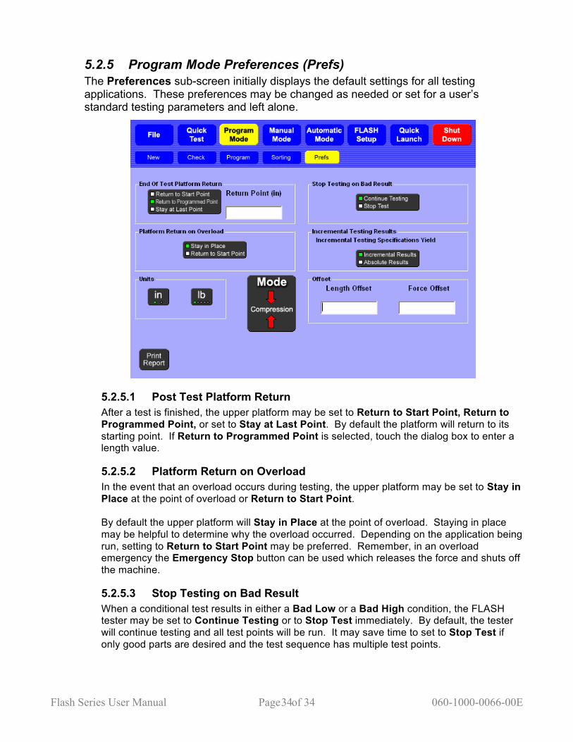
5.2.5 Program Mode Preferences (Prefs) The Preferences sub-screen initially displays the default settings for all testing applications. These preferences may be changed as needed or set for a user’s standard testing parameters and left alone.
5.2.5.1 Post Test Platform Return After a test is finished, the upper platform may be set to Return to Start Point, Return to Programmed Point, or set to Stay at Last Point. By default the platform will return to its starting point. If Return to Programmed Point is selected, touch the dialog box to enter a length value.
5.2.5.2 Platform Return on Overload In the event that an overload occurs during testing, the upper platform may be set to Stay in Place at the point of overload or Return to Start Point. By default the upper platform will Stay in Place at the point of overload. Staying in place may be helpful to determine why the overload occurred. Depending on the application being run, setting to Return to Start Point may be preferred. Remember, in an overload emergency the Emergency Stop button can be used which releases the force and shuts off the machine.
5.2.5.3 Stop Testing on Bad Result When a conditional test results in either a Bad Low or a Bad High condition, the FLASH tester may be set to Continue Testing or to Stop Test immediately. By default, the tester will continue testing and all test points will be run. It may save time to set to Stop Test if only good parts are desired and the test sequence has multiple test points.
Flash Series User Manual Page of 35 060-1000-0066-00E 35
5.2.5.4 Incremental Testing Results Certain test commands can be performed in either Absolute or Incremental mode (see section 5.2.3.2). When a test command is performed in Incremental mode, the result can be returned in either incremental or absolute results. By default, incremental testing returns incremental results. In Absolute mode, the forces and lengths (both specifications and results) reference a fixed zero point. In Incremental mode, the forces, lengths, and results are given as deflection amounts. There is an option available that specifies that the results of incremental test be given as Absolute measurements.
5.2.5.5 Units of Measurement In the Units section there are two buttons that control what units are used during testing for length and force. When the unit of measurement is changed, all test points and results are converted to reflect the new unit selection.
5.2.5.5.1 Length Choose between inch (in) and millimeter (mm). By default, the unit of measurement is inches.
5.2.5.5.2 Force Choose between pound (lb), Newton (N), gram (g), kilogram (kg), and ounce (oz). By default, the unit of measurement is pounds.
5.2.5.6 Mode This option selects the testing convention of either Compression or Extension.
5.2.5.6.1 Compression For compression tests the upper platform will move towards the lower platform to increase force.
5.2.5.6.2 Extension For extension tests on current FLASH testers, the upper platform moves away from the lower platform to increase force. An extension length initialization must be performed to use extension mode the first time. Test fixtures, usually some type of hooks, are attached to both platforms. Note: Future STAR or RoboSTAR models, including the ASSP, that have the Extension Bridge Assembly installed will extend the spring from the top of the bridge as the upper platform moves downward. FLASH software versions 2.40 and earlier do not support extension testing using the Extension Bridge Assembly.
5.2.5.7 Offset The Length Offset moves the length zero point and the Force Offset moves the force zero point. Offsets are generally used to compensate for the installation of test fixtures or the weight of the part being tested. When an offset is used, the force and / or length readings account for the value entered as the offset.
5.2.5.8 Print Report Touch [Print Report] to generate a hard copy of the program run and print the resulting test data. See section 5.2.3.5 for more information. Check availability of this option.

Flash Series User Manual Page of 36 060-1000-0066-00E 36
5.3 Quick Test Password Protection Optional Use Quick Test to obtain test data for a part without knowing any of its characteristics. A generic predefined test is run that performs two compression passes to solid height on the part. The first pass determines the test points and the second determines the nominal value for the test points. Testing is based on the presets under [Prefs]. See section 5.3.3. NOTE: The Quick Test application is designed for compression springs. Consult LSI with any questions. If the part has coils that shift during compression the Quick Test will not work. Shifting coils will not produce an accurate solid height. If the coils shift, the preset force or length should be changed. Depending on the part or the capacity of the tester, the speed of the test can be adjusted to enhance the accuracy and minimize deflection. The Quick Test feature calculates the free length, the force required to reach solid height, the two points between free length and solid height (default is at 20% and 80% deflection from free length), and the rate between the two points during the first pass. During the second pass, the tester determines nominal test result values. The final result of the Quick Test is a 5-point test sequence that can be used to repetitively test like parts in the Automatic Mode. The 5-point sequence of test commands is as follows:
1. Free Length 2. Force @ Length (for first deflection) 3. Force @ Length (for second deflection) 4. Length @ Force (for solid height) 5. Rate (between test point 2 and 3)
This test can now be:
1. Viewed and fine tuned in the Program Mode 2. Run repetitively and data viewed in the Automatic Mode 3. Saved for future use, along with any test result data using File
Under Quick Test there are three sub-screen menus: Program, Actual Data, and Prefs.
Flash Series User Manual Page of 37 060-1000-0066-00E 37
5.3.1 Program
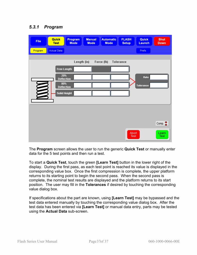
The Program screen allows the user to run the generic Quick Test or manually enter data for the 5 test points and then run a test. To start a Quick Test, touch the green [Learn Test] button in the lower right of the display. During the first pass, as each test point is reached its value is displayed in the corresponding value box. Once the first compression is complete, the upper platform returns to its starting point to begin the second pass. When the second pass is complete, the nominal test results are displayed and the platform returns to its start position. The user may fill in the Tolerances if desired by touching the corresponding value dialog box. If specifications about the part are known, using [Learn Test] may be bypassed and the test data entered manually by touching the corresponding value dialog box. After the test data has been entered via [Learn Test] or manual data entry, parts may be tested using the Actual Data sub-screen.
Flash Series User Manual Page of 38 060-1000-0066-00E 38
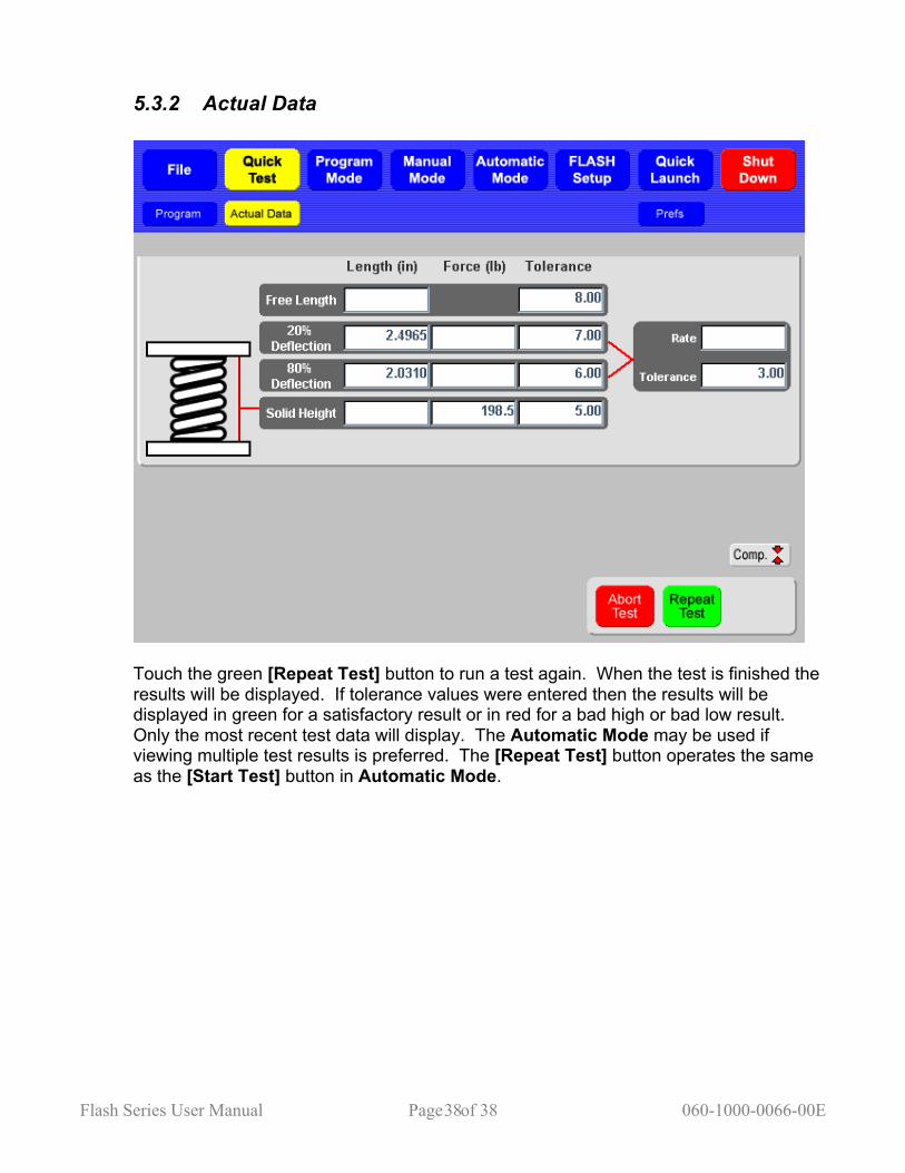
5.3.2 Actual Data
Touch the green [Repeat Test] button to run a test again. When the test is finished the results will be displayed. If tolerance values were entered then the results will be displayed in green for a satisfactory result or in red for a bad high or bad low result. Only the most recent test data will display. The Automatic Mode may be used if viewing multiple test results is preferred. The [Repeat Test] button operates the same as the [Start Test] button in Automatic Mode.
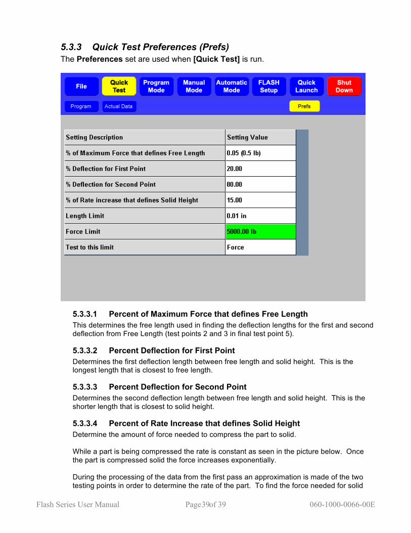
Flash Series User Manual Page of 39 060-1000-0066-00E 39
5.3.3 Quick Test Preferences (Prefs) The Preferences set are used when [Quick Test] is run.
5.3.3.1 Percent of Maximum Force that defines Free Length This determines the free length used in finding the deflection lengths for the first and second deflection from Free Length (test points 2 and 3 in final test point 5).
5.3.3.2 Percent Deflection for First Point Determines the first deflection length between free length and solid height. This is the longest length that is closest to free length.
5.3.3.3 Percent Deflection for Second Point Determines the second deflection length between free length and solid height. This is the shorter length that is closest to solid height.
5.3.3.4 Percent of Rate Increase that defines Solid Height Determine the amount of force needed to compress the part to solid. While a part is being compressed the rate is constant as seen in the picture below. Once the part is compressed solid the force increases exponentially. During the processing of the data from the first pass an approximation is made of the two testing points in order to determine the rate of the part. To find the force needed for solid
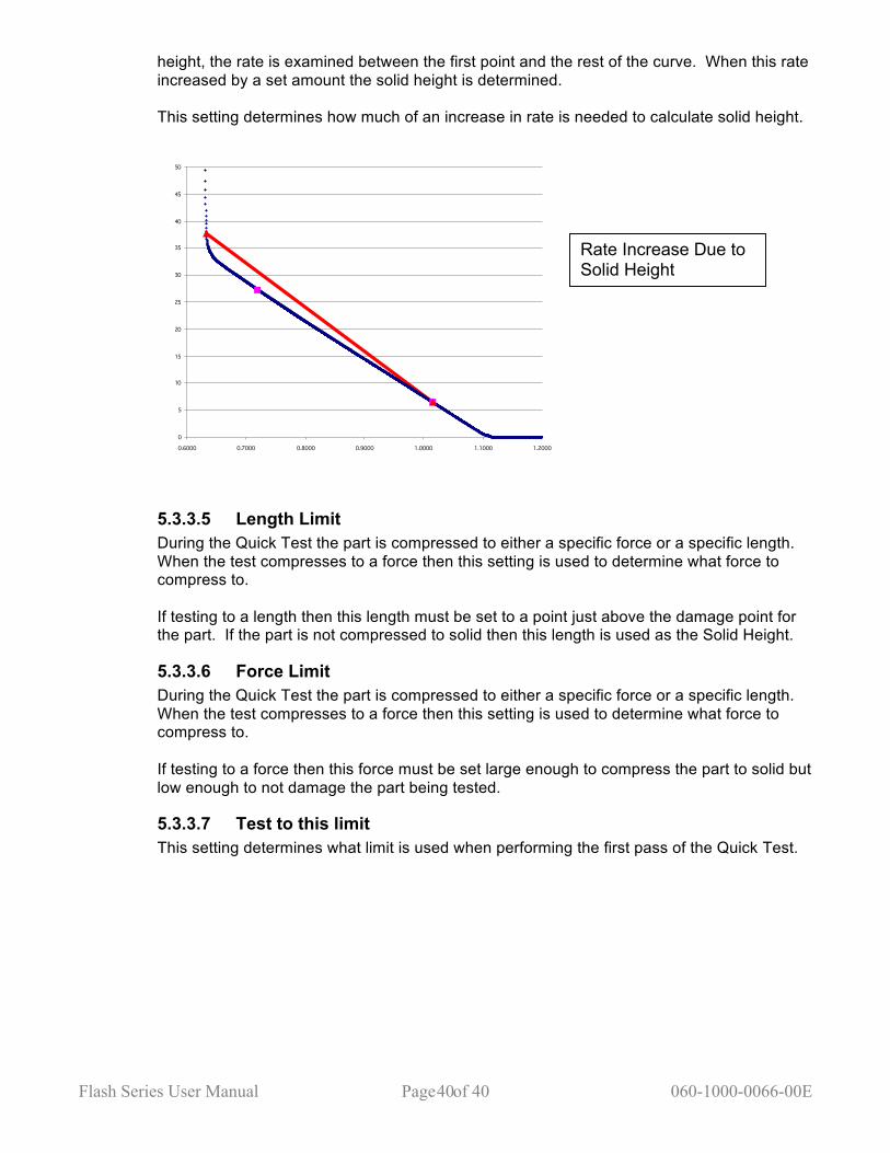
Flash Series User Manual Page of 40 060-1000-0066-00E 40
height, the rate is examined between the first point and the rest of the curve. When this rate increased by a set amount the solid height is determined. This setting determines how much of an increase in rate is needed to calculate solid height.
0
5
10
15
20
25
30
35
40
45
50
0.6000 0.7000 0.8000 0.9000 1.0000 1.1000 1.2000
5.3.3.5 Length Limit During the Quick Test the part is compressed to either a specific force or a specific length. When the test compresses to a force then this setting is used to determine what force to compress to. If testing to a length then this length must be set to a point just above the damage point for the part. If the part is not compressed to solid then this length is used as the Solid Height.
5.3.3.6 Force Limit During the Quick Test the part is compressed to either a specific force or a specific length. When the test compresses to a force then this setting is used to determine what force to compress to. If testing to a force then this force must be set large enough to compress the part to solid but low enough to not damage the part being tested.
5.3.3.7 Test to this limit This setting determines what limit is used when performing the first pass of the Quick Test.
Rate Increase Due to Solid Height
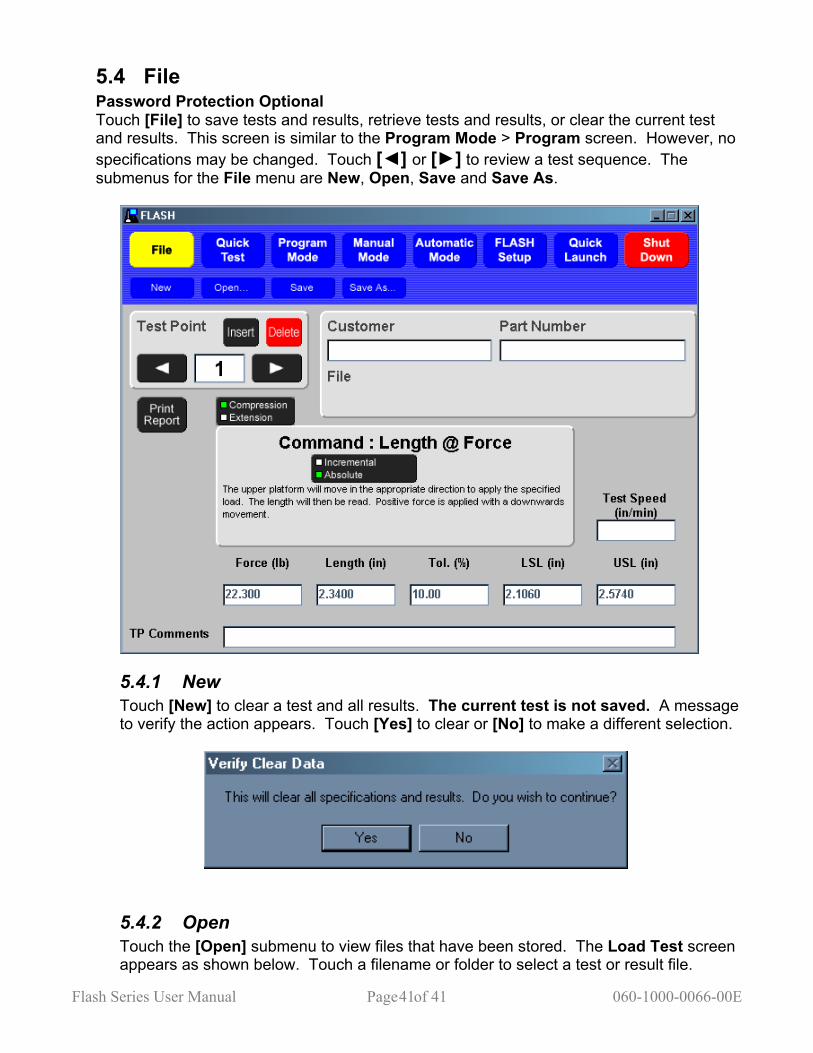
Flash Series User Manual Page of 41 060-1000-0066-00E 41
5.4 File Password Protection Optional Touch [File] to save tests and results, retrieve tests and results, or clear the current test and results. This screen is similar to the Program Mode > Program screen. However, no specifications may be changed. Touch [◄] or [►] to review a test sequence. The submenus for the File menu are New, Open, Save and Save As.
5.4.1 New Touch [New] to clear a test and all results. The current test is not saved. A message to verify the action appears. Touch [Yes] to clear or [No] to make a different selection.
5.4.2 Open Touch the [Open] submenu to view files that have been stored. The Load Test screen appears as shown below. Touch a filename or folder to select a test or result file.
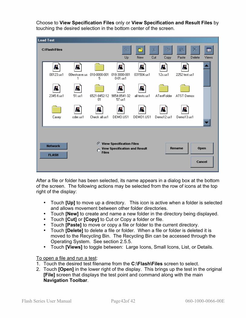
Flash Series User Manual Page of 42 060-1000-0066-00E 42
Choose to View Specification Files only or View Specification and Result Files by touching the desired selection in the bottom center of the screen.
After a file or folder has been selected, its name appears in a dialog box at the bottom of the screen. The following actions may be selected from the row of icons at the top right of the display:
• Touch [Up] to move up a directory. This icon is active when a folder is selected and allows movement between other folder directories.
• Touch [New] to create and name a new folder in the directory being displayed. • Touch [Cut] or [Copy] to Cut or Copy a folder or file. • Touch [Paste] to move or copy a file or folder to the current directory. • Touch [Delete] to delete a file or folder. When a file or folder is deleted it is
moved to the Recycling Bin. The Recycling Bin can be accessed through the Operating System. See section 2.5.5.
• Touch [Views] to toggle between: Large Icons, Small Icons, List, or Details. To open a file and run a test: 1. Touch the desired test filename from the C:\Flash\Files screen to select. 2. Touch [Open] in the lower right of the display. This brings up the test in the original
[File] screen that displays the test point and command along with the main Navigation Toolbar.

Flash Series User Manual Page of 43 060-1000-0066-00E 43
3. If the test program requires modification, select [Program] from the Navigation Toolbar. Use the arrow keys in the Test Point box to view or make changes. Add information like Customer or Part Number if desired.
4. Changes may be saved to the same filename by touching [File]>[Save] or to a new filename by touching [File]>[Save As].
5. To use the test program for running a test select [Automatic Mode] from the Navigation Toolbar.
6. Touch the green [Start Test] button to run. See section 5.5 for information on using Automatic Mode and selecting result views.
7. Multiple parts may be tested in this mode, generating a condition for sorting, and results saved, printed, or viewed.
Other Available Selections: • [Rename] – rename an existing file • [Network] – access the customer network allowing files to be shared via intranet. • [FLASH] – return to the “C:\Flash\Files directory screen • [Cancel] – go back to the previous screen
5.4.3 Save If the test already has a filename, the test specifications and results are saved under that file name again by touching [Save]. If the test specifications do not have a filename yet, the Save Test As screen opens. See section 5.4.4.
5.4.4 Save As… Touch [Save As…] to give test sequence specifications and results a filename when saving to storage for the first time. Navigate this screen with the same commands in section 5.4.2. Touch the New File Name dialog box to bring up the on-screen keyboard. Type a filename and touch [Enter].
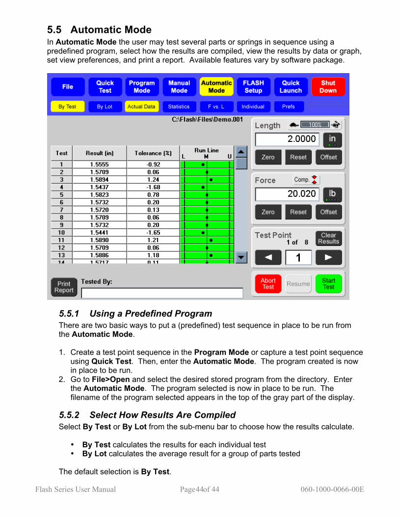
Flash Series User Manual Page of 44 060-1000-0066-00E 44
5.5 Automatic Mode In Automatic Mode the user may test several parts or springs in sequence using a predefined program, select how the results are compiled, view the results by data or graph, set view preferences, and print a report. Available features vary by software package.
5.5.1 Using a Predefined Program There are two basic ways to put a (predefined) test sequence in place to be run from the Automatic Mode. 1. Create a test point sequence in the Program Mode or capture a test point sequence
using Quick Test. Then, enter the Automatic Mode. The program created is now in place to be run.
2. Go to File>Open and select the desired stored program from the directory. Enter the Automatic Mode. The program selected is now in place to be run. The filename of the program selected appears in the top of the gray part of the display.
5.5.2 Select How Results Are Compiled Select By Test or By Lot from the sub-menu bar to choose how the results calculate.
• By Test calculates the results for each individual test • By Lot calculates the average result for a group of parts tested
The default selection is By Test.
Flash Series User Manual Page of 45 060-1000-0066-00E 45
5.5.3 Viewing Results This section describes the content of the various views available for the method of calculation. Preferences may be set for each individual view format. In section 5.5.4, the Preferences relevant to each view are described.
5.5.3.1 By Test or By Lot
5.5.3.1.1 Actual Data This view consists of a table / grid that lists each test point of a sequence and may show columns for actual numerical results, tolerances, and conditional results when applicable. Results are an average when Actual Data is calculated By Lot. The Actual Data grid can be viewed in either of two ways:
1. By Test Point (Tp) showing all of the test points for a single test, or 2. By Test showing all of the tests for a specific test point.
The desired view can be set in Preferences (Prefs) or switched by tapping the title at the top of the left column labeled “Tp” or “Test”. The conditional results can also be viewed two ways:
1. By Condition showing “Bad High”, “Satisfactory”, or “ Bad Low” statements, or 2. By a Run Line reflecting where the results fall in relation to the specified limits.
The desired view can be set in Preferences (Prefs) or switched by tapping the title at the top of the right column labeled “Condition” or “Run Line”.
5.5.3.1.2 Statistics This view shows the test results as statistical data that can be viewed as an average of all tests when By Test is selected. View the data as an average of a certain number of tests when By Lot is selected and lot size defined in Preferences.
5.5.3.2 By Test Only
5.5.3.2.1 F vs. L (Force vs. Length) A point is plotted on a chart for each test point that has both force and length data. By testing multiple points, a representative curve is displayed. If the test sequence included a test point for both the compression and release strokes, the chart would be able to display hysteresis. Chart limits for each point may be set in Preferences (Prefs) or by tapping on the axis labels. Clear the zoom to change the chart limits to the load cell maximum and length maximum.
5.5.3.2.2 Individual In graphical format, this view shows all of the results for a single test point for all of the parts tested. Shift the chart over the test points using the right and left arrows. Touch chart labels along either axis to zoom in. Touch [Clear Zoom] or [Undo Zoom] to reset or manipulate graph. Chart limits may be set in Preferences (Prefs) or by tapping on the chart labels to zoom. Clear the zoom to change the chart limits to the load cell maximum and the length maximum.
5.5.3.3 By Lot Only
5.5.3.3.1 X-Bar / R-Chart The X-Bar graph is similar to the Individual graph except that each point represents the mean of the group data. The R-Chart represents the range of results within the group data. The two may be viewed individually or on the same chart. If viewing individually use [Show Range] and [Show X-Bar] to switch views. Touch [Prefs] when viewing this chart to change settings.

Flash Series User Manual Page of 46 060-1000-0066-00E 46
5.5.3.3.2 Histograms This graph shows how the data groups together and how the normal line would appear. For a symmetrical group of data, the normal line would look like a bell curve. The histogram limits will be the specification limits, the +/- sigma limits, or actual results. The histogram is divided into 10 sections over the limits.
5.5.4 Automatic Mode Preferences (Prefs) When using the Automatic Mode and By Test or By Lot has been selected (highlighted in yellow), a results view may be selected as described in the previous section. At any of the combinations of By Test / By Lot with a result view, a different preference screen can be accessed that is specific to the view that is highlighted by touching [Prefs]. This section describes the variables that may be set for each.
5.5.4.1 Actual Data • View by Tp or by Test • View conditional results by Condition or Run Line • Set the Lot Size (if applicable)
5.5.4.2 Statistics • Set the Lot Size (if applicable)
5.5.4.3 F vs. L • Set axis limits manually • Show specification limits • X and Y axis max / min force and length
5.5.4.4 Individual • Set axis limits manually • Show specification limits • Show the mean line • Show the +/- 4 Sigma control lines • Minimum / maximum test points (Tp) displayed on X axis
5.5.4.5 X-Bar / R-Chart There are a number of preferences that may be set for this chart including:
• X-Bar and Range on same chart • Set axis limits manually • Show X-Double Bar line • Show Range Mean line • Show X-Bar specification limit line • Show +/- 4 Sigma control lines for both X-Bar and R-Chart • Set the Lot Size • X and Y axis max / min for both X-Bar and R-Chart
5.5.4.6 Histogram • Specification limits • +/- Sigma limits • Actual results • Set the Lot Size
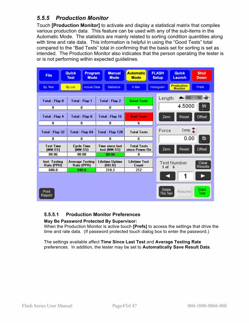
Flash Series User Manual Page of 47 060-1000-0066-00E 47
5.5.5 Production Monitor Touch [Production Monitor] to activate and display a statistical matrix that compiles various production data. This feature can be used with any of the sub-items in the Automatic Mode. The statistics are mainly related to sorting condition quantities along with time and rate data. This information is helpful in using the “Good Tests” total compared to the “Bad Tests” total in confirming that the basis set for sorting is set as intended. The Production Monitor also indicates that the person operating the tester is or is not performing within expected guidelines.
5.5.5.1 Production Monitor Preferences May Be Password Protected By Supervisor: When the Production Monitor is active touch [Prefs] to access the settings that drive the time and rate data. (If password protected touch dialog box to enter the password.) The settings available affect Time Since Last Test and Average Testing Rate preferences. In addition, the tester may be set to Automatically Save Result Data.
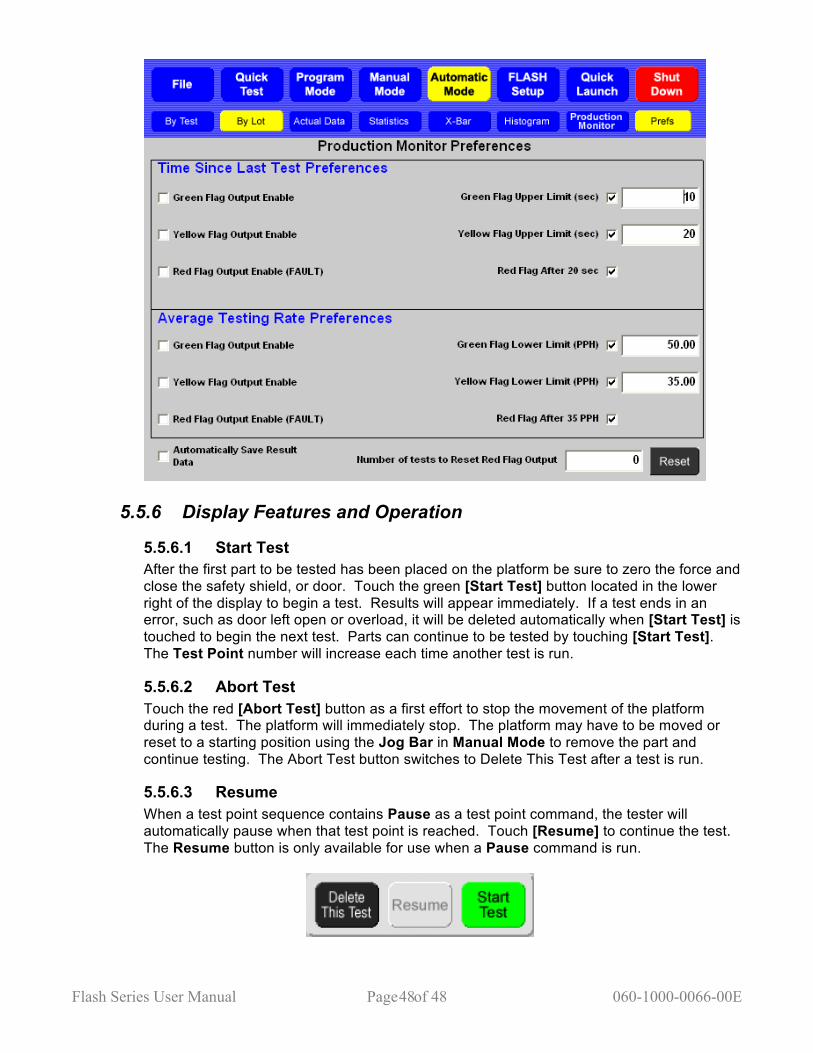
Flash Series User Manual Page of 48 060-1000-0066-00E 48
5.5.6 Display Features and Operation
5.5.6.1 Start Test After the first part to be tested has been placed on the platform be sure to zero the force and close the safety shield, or door. Touch the green [Start Test] button located in the lower right of the display to begin a test. Results will appear immediately. If a test ends in an error, such as door left open or overload, it will be deleted automatically when [Start Test] is touched to begin the next test. Parts can continue to be tested by touching [Start Test]. The Test Point number will increase each time another test is run.
5.5.6.2 Abort Test Touch the red [Abort Test] button as a first effort to stop the movement of the platform during a test. The platform will immediately stop. The platform may have to be moved or reset to a starting position using the Jog Bar in Manual Mode to remove the part and continue testing. The Abort Test button switches to Delete This Test after a test is run.
5.5.6.3 Resume When a test point sequence contains Pause as a test point command, the tester will automatically pause when that test point is reached. Touch [Resume] to continue the test. The Resume button is only available for use when a Pause command is run.

Flash Series User Manual Page of 49 060-1000-0066-00E 49
5.5.6.4 Delete This Test Once a test has been run the Abort Test button will change to “Delete This Test”. The operator may touch [Delete This Test] to delete or touch [Start Test] to continue testing. Once the next test is started, the previous test run is fixed and reported. Only the last test run may be deleted.
5.5.6.5 Print Report Touch [Print Report] to generate a printed report if tester has this feature. However, the Preview function may be used even if a printer is not connected. See section 5.2.3.5.
5.5.6.6 Tested By Touch the dialog box below Tested By to enter the name of the person performing the tests using the on-screen keyboard. The name entered appears on the printed report and stored with the results file.
5.5.6.7 Length Display The Length Display functions the same as in Manual Mode except that there is no [Go To] feature.
5.5.6.8 Force Display The Force Display functions the same as in Manual Mode except that there is no [Go To] feature.
5.5.6.9 Test Number By using the right or left arrows, each individual test point and test result can be viewed unless viewing all test results, statistics or individual chart. Touch [Clear Results] to clear test results and leave the test specifications intact. A message will appear to verify this action.
For detailed instructions on creating a test program and running it in Automatic Mode, see section 6 – Examples of Test Programs.
5.6 Quick Launch Password Protection Optional The Quick Launch feature is designed to give the user quick access to a specific test. This is handy when a test needs to be run on a part when in the middle of testing other parts. Quickly access Quick Launch: select a test, run the test, view results and go back to testing. No need to set up or program a test. There are three sub-screens under Quick Launch:
• Launch – select and run a customized test sequence from here • Configure – edit or delete a launch button • Add – define and add a new program button to the launch screen

Flash Series User Manual Page of 50 060-1000-0066-00E 50
5.6.1 Launch Select any blue quick launch button from the gray section of this screen. See 5.6.3 – Add for instructions to set up Quick Launch buttons. The Quick Launch screen shown below has four buttons set up labeled by name, part number or other description. The screen can accommodate about 50 buttons. When a blue quick launch button is selected, the tester will go to the screen specified to open when the button was created and added to the display. The user will be able to immediately run the test.

Flash Series User Manual Page of 51 060-1000-0066-00E 51
5.6.2 Configure Touch [Configure] to edit or delete an existing button. Select the Quick Launch button from the directory. The following screen appears:
The user may edit the Name, choose a different Specification File change the Screen To Open information, or add Print Setup specifications. Touch a dialog box to make changes. When changes have been entered, touch [Accept Changes] to save. Touch [Remove] to instantly delete a quick launch button. Touch [Cancel] to go back to the previous screen. The [Clear] buttons next to the dialog boxes will erase the data from the corresponding box.
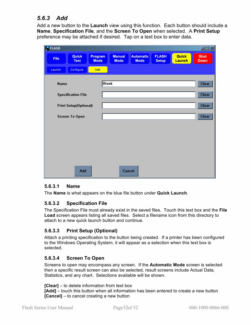
Flash Series User Manual Page of 52 060-1000-0066-00E 52
5.6.3 Add Add a new button to the Launch view using this function. Each button should include a Name, Specification File, and the Screen To Open when selected. A Print Setup preference may be attached if desired. Tap on a text box to enter data.
5.6.3.1 Name The Name is what appears on the blue file button under Quick Launch.
5.6.3.2 Specification File The Specification File must already exist in the saved files. Touch this text box and the File Load screen appears listing all saved files. Select a filename icon from this directory to attach to a new quick launch button and continue.
5.6.3.3 Print Setup (Optional) Attach a printing specification to the button being created. If a printer has been configured to the Windows Operating System, it will appear as a selection when this text box is selected.
5.6.3.4 Screen To Open Screens to open may encompass any screen. If the Automatic Mode screen is selected then a specific result screen can also be selected, result screens include Actual Data, Statistics, and any chart. Selections available will be shown. [Clear] – to delete information from text box [Add] – touch this button when all information has been entered to create a new button [Cancel] – to cancel creating a new button

Flash Series User Manual Page of 53 060-1000-0066-00E 53
5.7 FLASH Setup There are five selections within the FLASH Setup menu: Factory, Calibration, User, Print Setup, and Supervisor. They are password protected or accessible as noted in their descriptions below. There is also a button configured separately from the main selection menu identified as [Access Operating System]. Certain tester configurations may require an end user to access this password-protected menu.
5.7.1 Factory Password Protected Factory setup is done at Larson Systems for each new tester and should never be accessed by the end user. Changes to factory settings could degrade performance of the FLASH tester or disrupt the FLASH program entirely. Intentional changes to the Factory settings by the end user may void the warranty.
5.7.2 Calibration Password Protected Calibration is used to adjust settings affecting the measurement accuracy of the FLASH tester. This feature should only be accessed and used by LSI trained calibration technicians.

Flash Series User Manual Page of 54 060-1000-0066-00E 54
5.7.3 User Password Protection Optional User setup displays tester settings accessible by the user. Default settings have been preset at the factory and may not need any adjustment by the user. Some of the items are general information about the FLASH tester like the software version and serial number. Other settings control test speed, standard deviation, input and output signal diagnostics, and sorting flap status to name a few. This is a good place to view and modify settings that may affect test specifications.
5.7.4 Print Setup Password Protection Optional Print Setup displays the settings for report printout and shows an example of the standard printout. Different report printouts can be configured and saved for use with appropriate test applications using this menu. When [Print Setup] is selected from the FLASH Setup menu, a menu bar of black action buttons appears with an example report below it. The action buttons are Save Info, Load Info, and Preview followed by four selection buttons. This section describes how to use this screen and what each item and action button does. When using the Print Setup screen start with the Example Report. There are three columns titled Setting Description, Order, and Setting Value. Navigate this report by touching the scroll bar on the right side of the screen. Touch the title of a setting description to see the details and options for that section.

Flash Series User Manual Page of 55 060-1000-0066-00E 55
5.7.4.1 Setting Description There are seven categories that identify sections of the example report on the left side: 1. Print Company Name – When details are shown, if the Company Name has not been
entered, touch this item to open the on-screen keyboard, type in company name and touch enter. Do the same for City Name.
2. Print Heading – The only option in this section printing the LSI calibration date of the tester on the report. Touch to toggle between Yes or No.
3. Print specs – There are no option selections for printing test specifications from here. Use the black selection button above the report example to select Regular or Quick Test. This changes the specifications printed within this section.
4. Print Results – The options are Print Tp Results, Point 1 (Yes or No) and Print Tp Run Line (Yes or No). Use the black selection button above the report example to select results printed in this section as Actual Data or Lot Data (By Test or By Lot).
5. Print Statistical Summary – There are a number of options listed by statistic. Some of the statistics may not be relevant for a particular test and may be omitted here. Just touch the Setting Value to change.
6. Print Text Histogram – There are no options for printing a text histogram. 7. Print Individual Chart – The only option is printing an individual chart by point. If Yes is
selected a chart will print on the report for each point of the test.
Next make sure the black Selection buttons above the chart have been set as desired.

Flash Series User Manual Page of 56 060-1000-0066-00E 56
5.7.4.2 Selection Buttons • By Test or By Lot – this selection defaults to By Test. Change to By Lot if an average
representation of a group of results is needed. • Regular or Quick Test – this selection defaults to Regular. Change to Quick Test if
using results from a Quick Test program. This will define the Test Specifications section of the report.
• All Results or Single TP – this selection defaults to All Results. Change to Single TP if only looking at one test point’s results.
• Margins or Print Setup – this selection defaults to Print Setup. If the margin settings of the report need to be changed, switch selection to Margins and make changes. Touch again to return to Print Setup.
Once Print Setup selections have been made the action buttons may be used.
5.7.4.3 Save Info Select [Save Info] to open the “Save Print Out Setup Info As” screen. Save any particular print setup configuration with its own filename and use when needed. This feature allows the user to save multiple report printout schemes to be used with certain test applications. This screen operates the same as in File > Save As described in section 5.4.4.
5.7.4.4 Load Info Once Print Setup files have been saved select [Load Info] to access these files. Choose the report print out format desired for a particular test application. Once a report has been printed a user may decide to change the printout format for the same data. Return to this screen and load a different file.
5.7.4.5 Preview Select [Preview] to view how actual test results appear in the format selected.
Using Print Setup, a user may set the options desired and just print as needed after any testing application is completed. However, the Print Setup feature can also be used to customize individual printed reports and save much time. If after a test is complete, the user would like to change the printout settings just go to the Print Setup screen and go through the report as described in this section. Toggle between Preview and the main screen to view actual changes. Return to the menu where the test results were obtained and print the customized report from there. Or, save a variety of tests for particular needs. Once testing is complete go to the Print Setup screen and touch [Load Info] to retrieve the desired printout and return to the testing menu and print.
5.7.5 Supervisor Password Protected This is intended for use by a supervisor or authorized person at the end user location. An authorized person should receive the password for accessing these settings with the shipment of the tester from the factory. Contact LSI if password access is needed. Using the Supervisor menu, an authorized person can control access to individual menus by setting passwords as desired. For example, this feature could be used to distinguish between someone who is authorized to change, create, and manage test programs and someone who would be only authorized to run the tests.
Flash Series User Manual Page of 57 060-1000-0066-00E 57
It can be set up for complex hierarchy levels or just a simple password to prevent use of one menu by an unauthorized person. Password Setup Under the Setting Description column on the left are the Password setting descriptions. Each Setting Value field to the right of each item is normally blank meaning no passwords have been set to restrict access. To set a password, just touch the Setting Value blank next to the item. An on-screen keypad will appear for numeric or alpha and numeric characters.
5.7.6 Access Operating System Password Protected Access to the operating system is password protected. The FLASH tester runs on a Microsoft Windows operating system. Windows is setup to work with LSI’s FLASH software program. Changes made to the Windows operating system that interferes with the FLASH software may void the warranty. This button is accessible from any of the FLASH Setup menus except Print Setup. An end user authorized person may access the operating system using the password shipped with the tester. Only certain settings should be accessed and changed by the end user. They are: Add a Printer, Workgroup Name for Network Settings, and File Sharing. Certain operating system settings require test or numerical input. This requires a USB keyboard connected to the tester in order to enter this type of data. Access to the operating system allows the user to add a printer, change the Workgroup for Network access, or change folder permission for the C:\Flash\Files saved to that drive without voiding the warranty. Touch [Access Operating System] and a message appears titled Restricted Access that includes warranty information and a verification that the user would like to access the operating system. Touch [Yes] to access and enter the password. Contact LSI for password if not received.
6 EXTERNAL CONNECTOR INTERFACES This document will detail all of the external connectors on a FLASH Tester. The external connectors may be USB, Ethernet, RS-232, Remote Start, or VGA.
6.1 USB This connector is a USB-A connector and is a standard PC type connector. It can be used to connect devices such a keyboard and mouse, a printer, or a USB flash drive.
6.2 Ethernet This connector is a standard RJ-45 connector and is used to connect to a company’s Ethernet computer network.
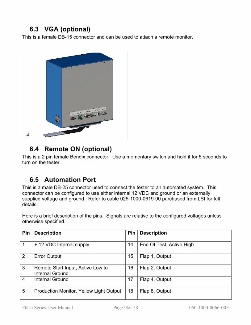
Flash Series User Manual Page of 58 060-1000-0066-00E 58
6.3 VGA (optional) This is a female DB-15 connector and can be used to attach a remote monitor.
6.4 Remote ON (optional) This is a 2 pin female Bendix connector. Use a momentary switch and hold it for 5 seconds to turn on the tester.
6.5 Automation Port This is a male DB-25 connector used to connect the tester to an automated system. This connector can be configured to use either internal 12 VDC and ground or an externally supplied voltage and ground. Refer to cable 025-1000-0619-00 purchased from LSI for full details. Here is a brief description of the pins. Signals are relative to the configured voltages unless otherwise specified. Pin Description Pin Description
1 + 12 VDC Internal supply 14 End Of Test, Active High
2 Error Output 15 Flap 1, Output
3 Remote Start Input, Active Low to Internal Ground
16 Flap 2, Output
4 Internal Ground 17 Flap 4, Output
5 Production Monitor, Yellow Light Output 18 Flap 8, Output
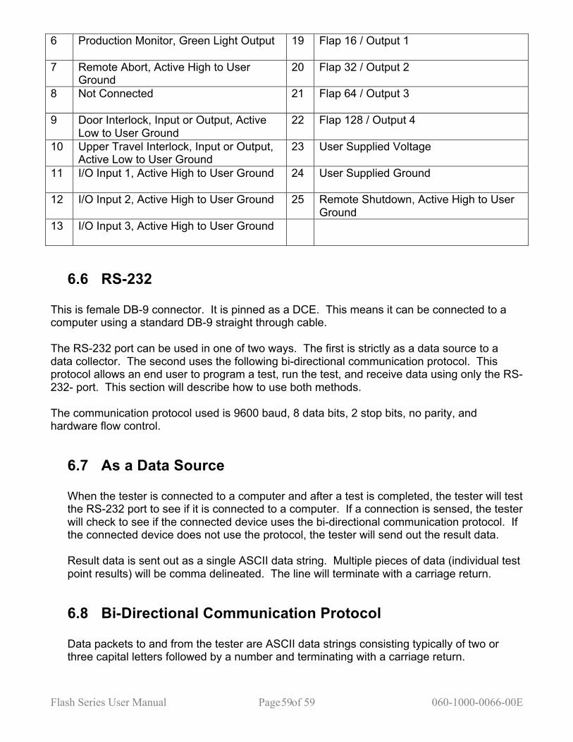
Flash Series User Manual Page of 59 060-1000-0066-00E 59
6 Production Monitor, Green Light Output 19 Flap 16 / Output 1
7 Remote Abort, Active High to User Ground
20 Flap 32 / Output 2
8 Not Connected 21 Flap 64 / Output 3
9 Door Interlock, Input or Output, Active Low to User Ground
22 Flap 128 / Output 4
10 Upper Travel Interlock, Input or Output, Active Low to User Ground
23 User Supplied Voltage
11 I/O Input 1, Active High to User Ground 24 User Supplied Ground
12 I/O Input 2, Active High to User Ground 25 Remote Shutdown, Active High to User Ground
13 I/O Input 3, Active High to User Ground
6.6 RS-232 This is female DB-9 connector. It is pinned as a DCE. This means it can be connected to a computer using a standard DB-9 straight through cable. The RS-232 port can be used in one of two ways. The first is strictly as a data source to a data collector. The second uses the following bi-directional communication protocol. This protocol allows an end user to program a test, run the test, and receive data using only the RS-232- port. This section will describe how to use both methods. The communication protocol used is 9600 baud, 8 data bits, 2 stop bits, no parity, and hardware flow control.
6.7 As a Data Source When the tester is connected to a computer and after a test is completed, the tester will test the RS-232 port to see if it is connected to a computer. If a connection is sensed, the tester will check to see if the connected device uses the bi-directional communication protocol. If the connected device does not use the protocol, the tester will send out the result data. Result data is sent out as a single ASCII data string. Multiple pieces of data (individual test point results) will be comma delineated. The line will terminate with a carriage return.
6.8 Bi-Directional Communication Protocol Data packets to and from the tester are ASCII data strings consisting typically of two or three capital letters followed by a number and terminating with a carriage return.
Flash Series User Manual Page of 60 060-1000-0066-00E 60
The types of commands can be broken down into three types : Specifications, Results, and Miscellaneous. All commands will be terminated with a carriage return when received and need to be terminated with a carriage return when sent.
6.8.1 Specification commands SR : Request the current specifications from the tester MR0 : Set or receive the request to clear all current specifications and results.
The third character is the number zero.
MR01 : Set or receive the request to clear the current results. The third and fourth characters are zero and one.
GL : Set or receive the current Length Offset This command will be followed by number that represents the current Length Offset.
GF : Set or receive the current Force Offset This command will be followed by a number that represents the current Force Offset.
GE: Set or receive the current testing method. This command is three characters long. GEC for compression or GEE for
extension.
MU : Set or receive the current measuring units. This command is four characters long. The third character is for Length or Angle and are as follows :
“I” for inches or degrees, “M” for millimeters or Revolutions.
The fourth character is for the Force or Torque and includes:
“L” for pound force or inch-pound torque “N” for Newtons force or Newton-millimeters torque “G” grams force or grams-millimeters “K” kilograms force or kilograms-millimeters “O” ounces force or inch-ounces “F” foot-pounds torque “M” Newton-meters torque “B” kilogram-meters torque “C” kilogram-centimeters torque
OR : Set or receive the Platform Return After Test option.
This command is composed of three characters and a number. The third character is the option’s value. “0” (zero) represents Return To Start Position. “1” represents Stay At Last Point, “2” represents Return to Specified Position. The number following the third character represents the Return to Specified
Flash Series User Manual Page of 61 060-1000-0066-00E 61
Position position. A value of “-100000000” represents Undefined, or none specified. Any another value represents a specific position. A number should always be send, even if it is the Undefined number.
OE : Set or receive the option Return on Overload option. This is a three-character command. The third character should be “0” (zero) for false (which means the platform remains at the position that caused the overload), or “1” for true (which means the platform returns to the starting point when an overload occurs.
OB : set or receive the Stop on First Bad option. This is a three-character command. The third character should be a “0” (zero) for false (which means the entire test sequence is completed), or “1” for true (which means the test will end prematurely if a test point tests bad).
OD : Set or receive the Flap Open time.
This command should be followed by a number that represents the amount of time the sorting flaps are opened, if the Flaps Open option is set to Timed. The number should be expressed in seconds.
OF : Set or receive the Default Sorting Flap This command is followed by a number that represents the default flap open if no sorting conditions are met when a sorting table has been defined.
OW : Set or receive the End Of Test Signal Width
A number following these characters represents the amount of time the End Of Test signal is given. It should be given in seconds.
OI : Set or receive the Incremental Test Result Type option This command will be 3 characters long. The third character will be “0” (zero) for incremental results, or “1” for absolute results.
OS : Set or receive the Sorting Table By itself, this command signals the beginning of the sorting table. When this command is given with a number following it, it represents an entry in the sorting table. full condition statement is: If (condition), Then (Flap). Each half of the statement is defined by using sets of two commands. Condition statements are given as two commands: OSx followed by OSy where x is a number that represents a test point to check and y is a number that represents the condition to apply. The conditions are: “1” = Satisfactory “2” = Bad Low “3” = Bad High “4” = Not Satisfactory “5” = Not Bad Low “6” = Not Bad High.
Flash Series User Manual Page of 62 060-1000-0066-00E 62
For example: an OS1 followed by OS2 represents “If Test Point 1 is Bad Low.” Multiple conditions can be ANDed together by giving multiple sets of OSx and OSy commands. The Then (Flap) is stored in the table as two commands, an OS0 (zero) followed by an OSx where x is a number that represents a Flap. Individual flaps are given as 1, 2, 4, 8, 16, or 32. If a situation arises, multiple flaps can be given at one time by adding together the numbers. For example, a 21 represents flaps 1, 4, and 16 together. The command “CC” should be given at the end of the table.
TP : Set or receive the current test point. This command should be followed by a number between 1 and 100. SC : Set or receive the current test point command.
The following are the current test point commands: L for Length @ Force F for Force @ Length P for Preset E for Free length K for Peak Force R for Rate A for Pause D for Delay I for Initial Tension B for Keypad Entry J for End Z for Fatigue 2 for Dynamic To Length 3 for Dynamic To Force 4 for Dynamic To Tome 5 for Signal I/O 6 for Position
SL : Set or receive the Specified Length This command will have a number following it. Typically, it will be a number that represents a position. For the Keypad entry, there will be a “C” followed by a number that represents the nominal value. For Signal I/O, it represents the amount of time the signal is on. For Rate, it is the first test point use to calculate the rate.
SF : Set or receives the Specified Length. This command will have a number following it. Typically it will be a number that represents a force. For Keypad entry, there will be an “O” (letter ohh) followed by a string that represents the units of the measurements; blank if none. For Dynamic to Length and Dynamic to Time the number will represent the measurement Interval Type: “0” (zero) for Force, “1” for Length, and “2” for type. For I/O signal the number will represent the I/O signal pair to use “1”, “2”, or “3”.
ST : Set or receive the Specified Tolerance
Flash Series User Manual Page of 63 060-1000-0066-00E 63
This command will be followed by a number. The number represents the tolerance around the Nominal result value to be a satisfactory part. This value is expressed as a percentage.
SS : Set or receive the Specified Speed This command will have a number following it. Typically it will be a number that represents a speed in in/min or mm/min.
SI : Set or receive the measuring method: absolute or incremental. This command will have one character following it: “A” for absolute, or “I” for incremental.
S2 : Set or receive the Fatigue type. This command will have one character following it: “A” for fatigue to Length, or “I” for fatigue to Force.
SM : Set or receive the miscellaneous data. This command is used for certain tests and will have a number following it. The Preset command uses it for the number of cycles. The Rate command uses it as the nominal rate. The Keyboard command uses it for the prompt. The prompt shown on the screen must be programmed with an “N” in front of it, i.e., “NThis is the Prompt”. The Delay uses this as the delay time in seconds. The Fatigue command uses it as the cycle count. The Dynamic commands use this to list the Start and Stop interval condition.
SE : Set or receive user specified data. The user can specify up to 10 extra specifications, such as Part Number and Customer Name. They are transferred using the commands “SE:002xx” through “SE:011” where “xx” is the specified text. These command require the colon character after the “SE” characters. “SE:020x” sets or receives the Part Counting option. If “x” is a “0” (zero) the tester counts normally. If “x” is “1”, then the tester counts Serial Numbers and uses the Initial Serial Number option as the first test count. “SE:021x” specifies the Initial Serial Number value.
Fx : Set or receive the Archiving option. If this command is present, Archiving will be turned on (for Fatigue or Dynamic test only) and the x will be a number specifying the Archiving interval. If this command is not received or sent, archiving is turned off.
SO : Set or receive the Test Point Comment. Any text following these characters will be displayed in the Comment section of the Program screen.
ER : Receive an Error code. This command will be followed by a number that represents an error code.
Flash Series User Manual Page of 64 060-1000-0066-00E 64
6.8.2 Result commands RN : Receive the Result Test Number
This command will be followed by a number that represents the current test number.
RP : Receive the current Result Test Point This command will be followed by a number that represents the current Test Point.
AF : Receive the Absolute Force
This command will be followed by a number that represents the Absolute Force read when the test point finished.
AL : Receive the Absolute Length This command will be followed by a number that represents the Absolute Length read when the test point finished.
RR : Receive the Test Point Result This command will be followed by a number that represents the result of the test point.
RS : Receive the result of the Sorting Table
This command will be followed by a number that represents the result the sort table at the end of the test.
RE : Receive the Error value
This command will be followed by a number that represents the error condition if the test ended in an error.
RC : Receive the Test Point Condition
This command would be followed by a character the represents the condition of the test point: “L” for low, “H” for high, or “S” for good.
RG : Receive the Global Condition This command would be followed by a character the represents the overall condition of the test: “G” for good or “B” for bad.
6.8.3 Miscellaneous commands RL : The tester will send out the current Force RF : The tester will send out the current Length US : The tester will start a test.
Flash Series User Manual Page of 65 060-1000-0066-00E 65
7 EXAMPLES OF TEST PROGRAMS The examples are meant to help the user navigate through an actual test point sequence. The numbers here may not apply to all springs or parts – adjust values as needed.
7.1 Single Point Test Sequence This example uses a Force @ Length test point command programmed with a Nominal value and a Tolerance. Make sure the Length Home Point has been set before starting. The numbers given in the examples assume that length is in inches and force is in pounds. Set Up the Test Point Sequence: 1. Touch [Program Mode] on the Navigation Toolbar to start. 2. Touch [New] to clear out all specifications and results. Touch [Yes] to verify the action.
The Test Point resets to 1. 3. Touch [Select New Command]. 4. From the test command selection bar that appears touch [Force @ Length]. 5. Tap the text box below Length and enter a target length of 2.58. 6. Tap the text box below Force and enter 15.6. 7. Tap the text box below Tolerance and type in “10” for a 10 percent tolerance. 8. View the text box below LSL. The LSL display should read 14.04 and the USL display
should read 17.16. These values were automatically calculated from the Nominal and Tolerance values entered. Test point 2 (last test point) should read End Of Test.
9. A Customer and / or a Part Number may be entered with this program if desired by tapping the respective text boxes. Entering this information is not required.
Save the Test Point Sequence: 1. Touch [File] on the Navigation Toolbar. 2. Touch [Save] on the sub-menu just below the Navigation Toolbar. The “Save Test
As” screen opens if a particular test sequence has not been saved before. If a Part Number was entered in the Program Mode, it defaults as the programs filename otherwise the New File Name text box will be empty.
3. To enter a New File Name tap the corresponding text box and an on-screen keyboard appears. Type in the desired filename for the program and touch [Enter].
4. Touch [Save] located in the lower right area of the display to save the test specifications under the filename entered.
Run the Test Point Sequence: 1. Touch [Automatic Mode] on the Navigation Toolbar. (Retrieve the program under
File>Open and select if running the test at a later time.) 2. Choose to calculate results By Test or By Lot. The results will display as Actual Data
by default unless otherwise specified using another selection from the sub-menu. 3. Place the part to be tested in the center of the lower platform. The upper platform may
need to be moved to accommodate by touching [Manual Mode] and tapping the Jog Bar to raise the platform. Touch [Automatic Mode] to return and place the part on the lower platform. Close the safety shield before starting the test.
4. Touch [Zero] on the Force display if not at zero before starting a test. 5. Touch the green [Start Test] button located in the lower right of the display to begin the
test. The results will display in real time as the test is performed.
Flash Series User Manual Page of 66 060-1000-0066-00E 66
6. Because of the tolerance value, results will also show the condition of the part. To see how repetitive testing works run more tests on a few of the same part by repeating from step 3 – the Test Point number advances as each test is run.
After a few more tests have been run, switch views in the submenu to see the different ways the results can be seen. Refer to section 5.5.3.1 for viewing details. Making Changes to the Test Point Sequence: 1. If the displayed results are not as expected and specifications need adjustment, touch
[Program Mode]. (It may be necessary to Clear Results in Automatic Mode first.) 2. Use the arrows in the Test Point box to move to the test point being changed. In this
case, the Length, Force or Tolerance specifications may be adjusted for Test Point 1. 3. Once satisfied with the changes, touch [File]>[Save]. 4. To continue testing, touch [Automatic Mode]. 5. In the Test Number box touch [Clear Results] to clear out any displayed results from
the previous test if not already done. 6. Begin testing again from step 3 - Run the Test Point Sequence instructions above. Saving Test Results: To save the results touch [File]>[Save]. A file will be saved with the same program name followed by .001. As more results are saved the extension will increase to .002, .003, etc.
7.2 Multi-Point Test Sequence This example shows a three-point test using two Length @ Force test points and a Rate test point. The numbers given in this example are based on a load cell capacity of at least 110 lbs. Adjust the forces appropriately if using a tester of a lower capacity. Again, make sure the Length Home Point has been set before starting. Set Up the Test Point Sequence: 1. Touch [Program Mode] on the Navigation Toolbar to start. 2. Touch [New] to clear out all specifications and results. Touch [Yes] to verify the action.
The Test Point resets to 1. 3. Touch [Select New Command]. 4. From the test command selection bar that appears touch [Length @ Force]. 5. Tap the text box below Force and type 22.3 using the pop-up keypad to enter the target
force. 6. Tap the text box below Length and type in 2.34 to enter the nominal length. 7. Tap the text box below Tolerance and type in “10” for the percent tolerance value. 8. Touch the right arrow in the Test Point display to move to test point 2. 9. Touch [Select New Command]. 10. From the test command selection bar that appears touch [Length @ Force]. 11. Tap the Force text box and type in 75.3 to enter the target force for test point 2. 12. Tap the text box below LSL and type in 1.8. 13. Tap the text box below USL and type in 1.9. 14. View the Tolerance display. This value should read 2.7. The Length display should
read 1.85. Tolerance and Length are automatically calculated based on LSL and USL. 15. Touch the right arrow in the Test Point display to move to test point 3. 16. Touch [Select New Command]. 17. From the test command selection bar touch [Rate].
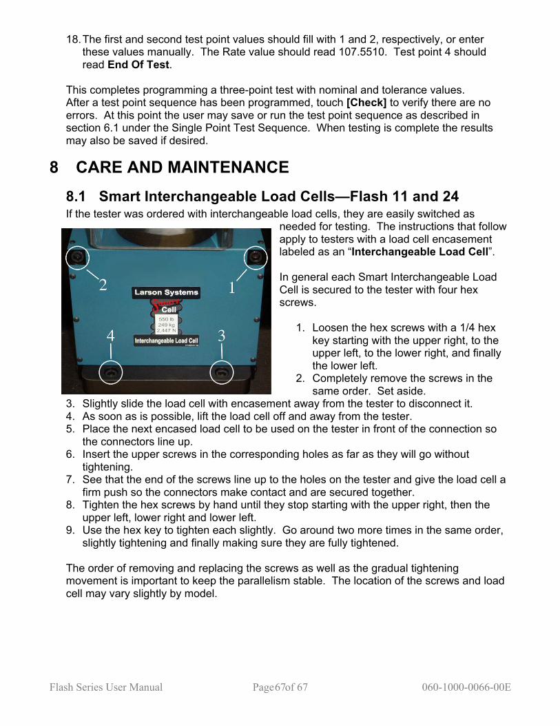
Flash Series User Manual Page of 67 060-1000-0066-00E 67
18. The first and second test point values should fill with 1 and 2, respectively, or enter these values manually. The Rate value should read 107.5510. Test point 4 should read End Of Test.
This completes programming a three-point test with nominal and tolerance values. After a test point sequence has been programmed, touch [Check] to verify there are no errors. At this point the user may save or run the test point sequence as described in section 6.1 under the Single Point Test Sequence. When testing is complete the results may also be saved if desired.
8 CARE AND MAINTENANCE 8.1 Smart Interchangeable Load Cells—Flash 11 and 24 If the tester was ordered with interchangeable load cells, they are easily switched as
needed for testing. The instructions that follow apply to testers with a load cell encasement labeled as an “Interchangeable Load Cell”. In general each Smart Interchangeable Load Cell is secured to the tester with four hex screws.
1. Loosen the hex screws with a 1/4 hex key starting with the upper right, to the upper left, to the lower right, and finally the lower left.
2. Completely remove the screws in the same order. Set aside.
3. Slightly slide the load cell with encasement away from the tester to disconnect it. 4. As soon as is possible, lift the load cell off and away from the tester. 5. Place the next encased load cell to be used on the tester in front of the connection so
the connectors line up. 6. Insert the upper screws in the corresponding holes as far as they will go without
tightening. 7. See that the end of the screws line up to the holes on the tester and give the load cell a
firm push so the connectors make contact and are secured together. 8. Tighten the hex screws by hand until they stop starting with the upper right, then the
upper left, lower right and lower left. 9. Use the hex key to tighten each slightly. Go around two more times in the same order,
slightly tightening and finally making sure they are fully tightened. The order of removing and replacing the screws as well as the gradual tightening movement is important to keep the parallelism stable. The location of the screws and load cell may vary slightly by model.
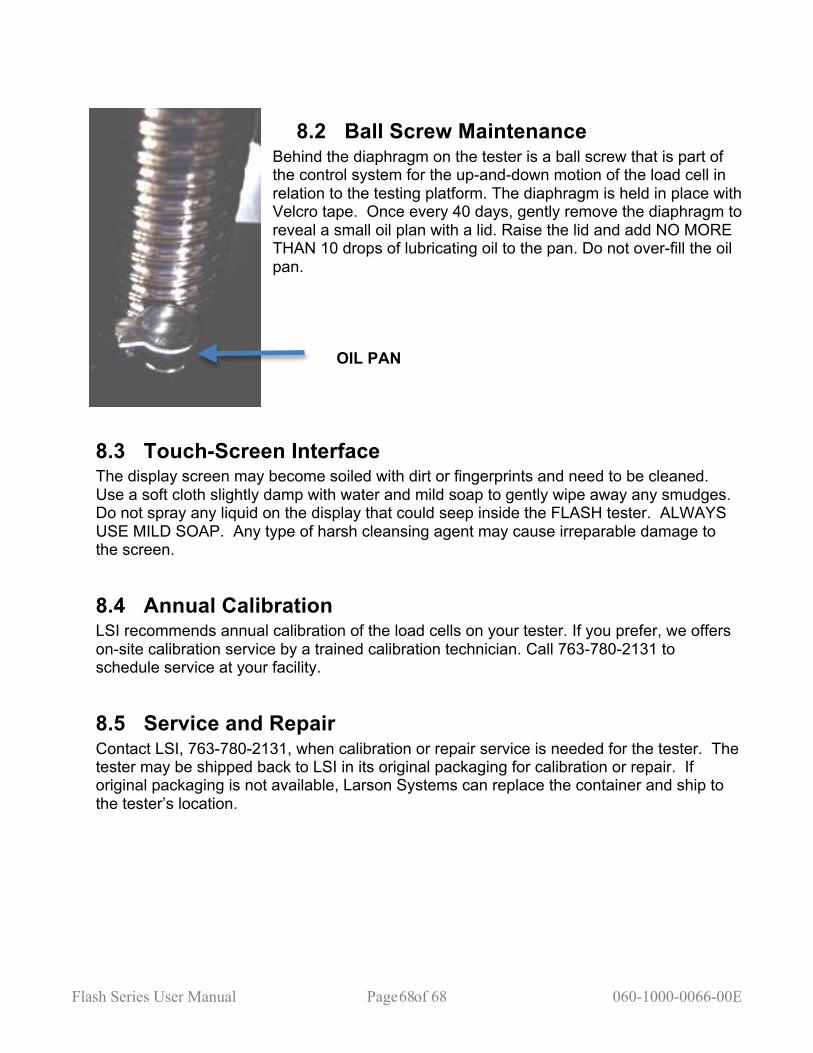
Flash Series User Manual Page of 68 060-1000-0066-00E 68
8.2 Ball Screw Maintenance Behind the diaphragm on the tester is a ball screw that is part of the control system for the up-and-down motion of the load cell in relation to the testing platform. The diaphragm is held in place with Velcro tape. Once every 40 days, gently remove the diaphragm to reveal a small oil plan with a lid. Raise the lid and add NO MORE THAN 10 drops of lubricating oil to the pan. Do not over-fill the oil pan.
OIL PAN
8.3 Touch-Screen Interface The display screen may become soiled with dirt or fingerprints and need to be cleaned. Use a soft cloth slightly damp with water and mild soap to gently wipe away any smudges. Do not spray any liquid on the display that could seep inside the FLASH tester. ALWAYS USE MILD SOAP. Any type of harsh cleansing agent may cause irreparable damage to the screen.
8.4 Annual Calibration LSI recommends annual calibration of the load cells on your tester. If you prefer, we offers on-site calibration service by a trained calibration technician. Call 763-780-2131 to schedule service at your facility.
8.5 Service and Repair Contact LSI, 763-780-2131, when calibration or repair service is needed for the tester. The tester may be shipped back to LSI in its original packaging for calibration or repair. If original packaging is not available, Larson Systems can replace the container and ship to the tester’s location.
Flash Series User Manual Page of 69 060-1000-0066-00E 69
Title Title to the described equipment shall remain in the seller until full, actual payment therefore shall have been made. In the event of a default, the seller shall have the right to repossess the said equipment and whatever monies shall have been paid on account shall be deemed to have been rental for the use thereof to the date of such repossession. The seller shall also have the right to hold the purchaser liable for a sum equivalent to the unpaid balance of the purchase price together with all expenses and damages that the seller may have sustained, the purchaser to receive credit however, for the net monies realized on the sale of the equipment. At the election of the seller, the seller may deem title to have passed to the purchaser, in which event the seller need not repossess the equipment, but may sue at law for the balance unpaid thereon. Warranty FLASH 11 and FLASH 24 parts and labor are warranted against defects in material and workmanship to the consumer for a period of twelve months from the date of purchase. This warranty covers all parts, except consumable items. It applies only to machines and accessories that have been installed and operated in accordance with instructions in our reference manuals, have not been tampered with in any way, misused, suffered damage through accident, neglect or conditions beyond our control and have been serviced only by authorized personnel. Larson Systems Incorporated is not responsible for loss in operating performance due to environmental conditions, such as humidity, dust, corrosive chemicals, deposition of oil or other foreign matter, spillage or other conditions beyond our control. There are no other warranties expressed or implied, and Larson Systems Incorporated shall not be liable under any circumstances for incidental or consequential damage. Warranty service is conducted at LSI’s facilities in Minneapolis, MN. Return the tester freight prepaid during the warranty period, and Larson Systems Incorporated will make a warranty determination, repair and return the tester freight collect. Shipments sent collect will be rejected.

Flash Series User Manual Page of 70 060-1000-0066-00E 70
Larson Systems Inc. 10073 Baltimore Street NE Minneapolis, MN 55449-4425 763-780-2131 Fax: 763-780-2182 1-877-780-2131 www.larsonsystems.com [email protected]