Embed Size (px)
Citation preview

SERI/STR-215-1879 January 1983
Large Wind Turbine Siting Handbook: Television Interference Assessment
Final Subcontract Report Thomas B. A. Senior Dipak L. Sengupta
Radiation Laboratory Department of Electrical and Computer Engineering University of Michigan
Prepared Under Subcontract No. EY-76-S-02-2846.A004

Printed in the United States of America Available from:
National Technical Information Service U.S. Department of Commerce
5285 Port Royal Road Springfield, VA 22161
Price: Microfiche $4.50
Printed Copy $10.00
NOTICE This report was prepared as an account of work sponsored by the United States Government. Neither the United States nor the United States Department of Energy, nor any of their employees, nor any of their contractors, subcontractors, or their employees, makes any warranty, express or implied, or assumes any legal liability or responsibility for the accuracy, completeness or usefulness of any information, apparatus, product or process disclosed, or represents that its use would not infringe privately owned rights.

) ,\
\ _}
) )
SERI/STR-215-1879 UC Category: 60
large Wind Turbine Siting Handbook: Television Interference Assessment
Final Subcontract Report
Thomas B. A. Senior Dipak L. Sengupta.
Radiation Laboratory Department of Electrical and Computer Engineering UJ1iversfty of Michigan
January 1983
Prepared Under Subcontract No. EY-76-S-02-2846.A004
SERI Technical Monitor: Neil Kelley
Solar Energy Research Institute A Division of Midwest Research Institute
1617 Cole Boulevard
Golden, Colorado 80401
Prepared for the
U.S. Department of Energy Contract No. EG-77 -C-01-4042

( I
I 1
I
ACKNOWLEDGEMENT
It·is a pleas ure to acknowl edge the s uggesti ons made by
Mr . Nei l Kel l ey of SERI duri ng preparati o n o f thi s Handbook .
-i-

ABSTRACT
The rotating blades of a horizontal axis wind turbine can distort
the video portion of a television signal and thereby interfere with
TV reception in the vicinity of the machine. The nature of this
interference is described and methods are presented for calculating
the zone within which the interference may be severe. Specific
results are given for the MOO-OA, MOD-1 and MOD-2 machines as functions
of the TV frequency.
- i i -
L
(

l. y
TABLE OF CONTENTS
Secti o n
1 . Introduct ion
2 . Interference Phenomena
3 . Modul ati o n Thresho l d a nd the Interference Zone
4 . Interference Zone Ca l cu l a ti ons
5 . Computed Val ues of r1 a nd r2
6 . Effects o f D i recti o nal Rece iv i ng Antennas
7 . TV I As s es sment Procedure
7 . 1 Method A 7 . 2 Method B
8. A Typi ca l TV I Ass essment
9. A Note on the Smooth Earth Model
1 0 . Conc l us i ons
1 1 . Append i x A : Computer-Gra phi cal Method for Calculati on
Page
1
2
4
1 0
1 1
1 4
1 5
1 5 1 6
20
22
2 2
o f the Interference Zo ne 25
A . l Theo reti cal Cons i d erati o ns A . 2 Computa t i o nal Procedures A.3 Spec i fi c Computati ons
1 2 . Append i x B : Gl os s ary o f Symbols
1 3. References
25 30 34
51
53

t·
1 . Introduct ion
The purpo s e o f thi s Handbook i s to show how to predi ct the
reg i o n where a large hori zontal axi s wi nd turb i ne (WT ) can s i gn i
fi cantly a ffect the rec epti o n o f televi s i on (TV ) s i gnals. Such
i n formation can a s s i st i n the s elect ion o f a s i te for a WT fac i li ty
and i n the analys i s o f the i nterference under a vari ety o f
ci rcumstances .
The Handbook i s a rev i s i o n o f one prev i ously publ i shed [ 1 ] and
differs from i t i n s everal parti cula rs . As a res ult of data tha t have
become ava i la ble s i nce that time i t is appa rent that a change i n
hei ght at which the WT reflects TV s i gnals can have just a s much
effect as a change i n the blade area res pons i ble for the reflecti on .
S i nce the tower hei ght used throughout [1 ] was 30 m , the curves g i ven
there are a ppli cable only tb a MOO-OA (or s i mi lar ) machi ne . In
addi t i on , o n- s i te and laboratory measurements o f WT- produced i nter
ference hav e shown that the modulati o n threshold used to s peci fy the
i nterference zone i ncreases w i th decreas i ng time delay o f the
s econda ry ( scattered ) s i gnal relat ive to the primary . Thi s not o nly
reduces the i nterferenc e zone rad i us i n the forward scatter i ng reg i o n
but als o perm i ts s ome s impli fi cati o n i n the method used to calculate
the enti re zo ne. Interference d i s tances are tabulated as functio ns
o f the frequency and d i s ta nce to the TV transm i tter for MOO- OA , MOD- 1
and MOD- 2 machi nes. For these s ame machi nes wi th blades o ther tha n
metalli c , i nformati o n i s prov i ded to enable the correspondi ng numbers
to be o bta i ned .
- 1 -

- 2-
The pres ent Handbook provides two methods for performing the
ass es sment of television interference or TVI effects of a large
horizontal axis WT after determini ng its interference zone: (i) Method
A , sufficient for a first order estimation of the interference zone ,
i s l ess ri gorous but comparativel y easier to applj ; and ( ii) Method B ,
suitable for more accurate. determination of the interference zone , is
more detailed but somewhat difficult to us e.
References [2-6] contain a deta i led description of the
theoretical and experi mental investi ga tions that have been performed ,
and the read er may w i sh to consult these. The TV interference is
intimately connected w i th the characteristics of radi o wave
propagati on over the earth and in the presence of the WT. It is
assumed that the waves propagate over a homogeneous smooth spherical
earth having a rad i us 6 .34 x 103 km , with relative permittivity s:r = 15 and conductivity cr = 0.01 siemens/m . The medium above the earth is
assumed to be free s pace and the effects of any terrain inhomogeneity
or irregularity are ignored .
2 . Interference Phenomena
It has been found [2] that the rotating blades of a horizontal
axis WT can interfere with TV reception by producing video distortion.
At a given distance from a WT the interference increases with
increas i ng frequency and is therefore wors t on the upper UHF Channels .
It al so decreases with increasing distance from the machine , but in
the worst cases can still produce objectionable video distortion at
distances up to a few kilometers. For ambient (primary ) signals well

r
- 3-
above the no i s e level o f the recei v er , there i s i n general no
s i gn i fi cant dependence on the amb i ent fi eld strength, a nd no aud io
di stort i o n has been obs erved .
The i nterference i s caus ed by the time- varyi ng ampli tude
modulati o n (AM ) of the recei ved s i gnal produced by the rotati ng
blades . In a ne i ghborhood o f a WT the s i gnals scattered by the blades
combi n e wi th the primary s i gnal to create a form of time-varyi ng
mul ti path , thereby ampli tude modulati n g the total recei ved s i gna l .
The ampl i tude modulati on waveform cons i s ts o f sync puls es repeati ng
at twi ce the rotat ion frequency o f the blades . The wi dth o f the
pul s es i s i nversely pro porti o nal to the electri cal length of a blade .
If s u ffi c i ently s trong , these extraneous pulses can di stort the recei ved
pi cture , whereas the audi o i nfo rmat ion , bei ng transmi tted by frequency
modulatio n , remai ns una ffected .
When the blades are s ta t i o nary the scattered sig nal may appear
on the TV screen as a ghost who s e pos i tion ( s eparat ion ) depends on the
di fference between the time delays suffered by the primary a nd
scattered s i gnals . A rotati o n o f the b lades then caus es the ghost to
fluctuate , a nd i f the ghost i s suffi c i ently strong , the res ulti ng
i nterference can be object ionable . In s uch cases the recei ved pi cture
d i splays a hori zontal j i tter i n synchron i s m wi th the blade rotat ion .
As the i nterference i ncreas es , the enti re ( fuzzy ) pi cture shows a
puls ed bri ghteni ng , and s t i ll la rger i nterference can di s ru pt the TV
recei ver•s v ert i cal sync , caus i ng the pi cture to roll over ( •fli p•) or
even break u p . Thi s type o f i nterference occurs when the i nterferi ng
s i gnal reaches the recei ver as a res ult o f scatteri ng , primar ily
s pecular , o ff the broad faces of the blade ( s ) . As the angle� ( s ee

-4-
Fi g . 1 ) b etween the WT-transmi tter and WT-recei ver di recti ons i ncreas es,
the separation o f the ghost decreas es, and a somewhat greater i nter-
ference is now requi red to produce the same amount o f vi deo d i s tort i on.
In the forward scatteri ng reg i o n when the WT is a lmo st i n l i ne between
the transmi tter and the recei ver, there is virtually no di fference
i n the times of arri val o f the primary and seconda ry s i gnals . The
ghost i s then s uperimposed on the undistorted pi cture and the vi deo
i nterference appears as an i ntensi ty ( br ightness) fluctuation of
the pi cture in synchronism wi th the blade rotation. In all cases,
the amount of i nterference depends on the strength of the scattered
s i gnal relati v e to the pri mary one, and thi s decreases wi th
i ncreas i ng distance from the WT.
3. Modulation Threshold and the Interference Zon e
For the purpose of the present d i scus s i on we use Fi g . 1 which
shows the l ocations of the distant TV transmitter ( T), the phase
center of the omn i di recti onal rece i v i n g antenna (R), and the scatteri ng
center (B) of a blade , all ass umed to l i e i n a hori zontal p l ane,
i .e . , the p l ane of the paper . It i s a l so assumed that the b l ade
rotates i n a vertical pl ane through M-M ( s ee Fi g. 1 ) , and that thi s
pl ane i s s o ori ented as to di rect the specularl y refl ected fi el d to
the receiver.
The extraneous ampli tude modul ati on index of the total fiel d
at R i s
m ( 1 )

phase center o f
the WT blade 8
- 5-
R (rec i ever 1 o f�,..
t_e_d
_a
_ t r_,_�
_) -----
<P' ( T
d
(di s tan t lV transmi tter )
Fi gure 1 . Geome try o f the WT blade scatteri n g .

- 6-
where ET( R ) is the ampl i tude of th e di rect ( or primary) fiel d at R and E8 ( R ) i s the ampl i tude o f the secondary (or scattered } fi el d wh i ch
reaches the recei ver a fter refl ection off a rotati ng bl ade of the WT.
The modul ati o n threshold m0 is defi ned as the l argest val ue
of the extraneous ampl itude modul ation index m of the recei ved s i gnal
for which the v ideo d i stort ion i s sti l l judged to be acceptabl e.
The threshold is obviously somewhat subjective, but as a result of
detail ed laboratory measurements [2], field tests [2,3], and
controlled measurements using a small scale model [4], it has been
established .for all TV Channels as 0.15 for q, = 0 i ncreas i ng to 0.35
for rp = 180 degrees as shown in Fig . 2. The threshold is largely
independent of the signal strength at the receiver a nd, for a given
WT, determi nes the maximum di stance from the WT at wh i ch the inter-
ference can still be objectionabl e .
On the assumption that the WT i s so ori ented ( i n azimuth) as
to di rect the maximum scattered signal to the recei ver, the region
where m > m0 i s defin ed as the i nterference zone [1,7]. That porti on
of the zone wh i ch i s produced by s pecular refl ecti on off the bl ades
is roughly a cardi oid centered at the WT wi th i ts maximum poi nt ing
towards the TV transmitter, and i s ca 11 ed the back\vard i nterference
region. There is a l s o a narrow l obe, cal l ed the forward i nterference
region , di rected away from the transmitter resu l ti ng from forward
scatteri ng off the bl ades . The s hape of the i nterference zone i s
sketched i n Fi g . 3 where rr and r2 may be i denti fi ed a s the backward
and forward i nterference distances , respectivel y, and thes e genera l l y
prov ide the maxi mum di stances from the WT at wh i ch objecti onabl e
i nterference can occur i n the two regions.

r )
0.4
0.2
-
0 .. -0
- 7-
- --· -·- .. ·-- ----- -·- p . - ::. ·· · - I . /
-- - -·- · - · ··· �- - . .. :- -· -���-·-··�--:- -- � · / -
- · . -- ·- -- - ·-
.. -- --
-
60
--.,.... -
:· -··· ·- ... -. ··-- . / .. · . .. / . . . ·-· _ ___ ; / . ·-- .. - . .
...,.. /
/
120
0 (degrees) ISO
Fi gure 2 . Chosen threshol d modul at i on i ndex m0(� ) a s a function o f
the angul a r po si ti on o f the rece i ver wi th respect to the
WT-transmi tter di rect i on .

<P = oo 0--R-
oi stant TV 1 Transmi tter
(not drawn to scale)
- 8-
Backward I nterference Region
Fi gure 3 . Sketch of the TV interference zone o f a WT.
r-. '
� .

l I,
_l I J
'(
)
l (
- 9-
I n the backward reg ion the i nterference i s general l y i ndependent
o f the ambi ent or primary s i gna l s trength , and the i nterference reg i on
i s obtai ned a s r = r (� ) for wh i ch m > m = 0 . 1 5 . T he fo rward region 0
i nterference i s somewha t dependent on the ambi ent s i gnal s trensth [3],
bei ng strongest i n fri nge a reas o f recepti on where the s i gnal
strength is l ow . The forward i nterference regi on is that for whi c h
m > m where m = 0 . 35 i n a s trong s i gna l area , decreas i ng uni fo rmly 0 0 to 0 . 1 5 when the amb i ent signa l i s wea k . Consequent ly , i n fri nge
areas r(�) = r2 > r(O) = r1 , i . e . , the forwa rd i nterference determi nes
the maxi mum i nterferenc e d i stance o f the WT . I n areas where the s i gnal
i s not weak the reverse i s genera l l y true , and r1 then determi nes
the max imum i nterference d i s tanc e . Knowi ng r1 and r2 , the i nterference
zone of a WT can be approx imatel y obtai ned from [ 1 , 7]
r (� ) r1 cos t 0 < I � I A = ' < � - re and 1TL
s i n[ T s i n � ] A r(� ) = r2
�
--
< I � I < � �L Le T s i n �
where Le i s the equ i va l ent l ength o f the WT b l ade and A i s the
wavel ength .
As sumi ng now that the maximum scattered fi el d at R ( i . e . ,
E8(R)) i s di rectl y proprot ional to the equi val ent scatter i ng area
Ae of each bl ade and i nverse ly pro port ional to the d i stance r from
the WT ( Fi g . 1), the two i nterference d i stances are approxi �atel y
gi ven by (7]
(2)
( 3)
(4)

-10-
where R1 = (r1,0 ), R2 = (r2,rr ) (see Fig. 3) and ET ( B ) is the amplitude
of the direct (ambient ) field of the TV transmitter at the WT blade 8.
It is evident that knowledge of Ae and of the secondary to
prima ry field ratio, i.e., E8 (R)/ET (R) at R, or of the ratio of the
primary (ambient) fields at Sand R, i.e., ET(B)/ET(R), is
necessary to determine r1 and r2 and, hence, the interference zone.
Theoretical determination of both of thes e ratios requires the use of
rigorous field expressions and the elaborate numerical computation
discussed in [1,2]. However, interference zone calculations become
much simpler if the ambient field strength ratio is known from
measurements made at the wind turbine s ite and at receiver locations.
For a rough assessment of the television i�terference ( TVI ) associated with a WT it is sufficient to obtain r1 and r2 as a function
of frequency.
4 . Interference Zone Calculations
The calculation of the interference zone of a WT is based on the
theoretical expressions for the fields derived in [2] and the compu
tational procedure discussed in [1 ]. The computer program is itself
an extension of one developed [8] for calculating ground wave
propagation over a homogeneous spherical earth. The transmitting
and receiving antennas are assumed omnidirectional and horizontally
polarized, and located at heights h1 and h2, respectively, above the
earth's surface. The height of the scattering or phase center of the
blade is h3• At a given frequency and for given h1, h2 and h3, the
program computes the field quantities ET(R) and/or ET(B) as functions
r --
' .
/C -
••
�-

(
-11-
o f the great c i rcl e di stance ( d ) from th e transmi tter and the
scattered fi el d E8 ( R ) as a functi o n of the di stance ( r ) from the WT.
Though the progra� can handl e any s pec i fi ed val ues for the rel ati ve
perm i tti v i ty er and conducti v i ty a of th e earth a nd a ny earth radi us
( a ) corrected to account for atmos pheri c refracti on , the computat i o ns
were al l performed fo r the val ues :
a = 6.34 x 1 03 km , a = 0 . 0 1 s /m
W i th the frequency f and di s tance d as i n puts , the quanti ti es
E8
( R ) a nd ET ( R ) are obta i ned at a s equence of di s tances from the WT
a l ong the same great c i rc l e path from the transmi tter . From a
v i sual compa ri son of the two s ets o f data , the farthest po i nts
on e i ther s i de of the WT at wh i ch m = m0 are l ocated . These s peci fy
the two di stances r1 and r2 • I f des i red , the actual i nterference
zone can be found by sol v i ng ( 1 ) wi th m = m0 or estimated by us i ng (2) a nd ( 3) . As i s evi dent , however , the process requ i res computati o n
o f a whol e new s er i es o f fi e l d stren gth val ues fo r every TV
transm i tter and i ts di s tance from the WT . A s impl er graphi cal method
whi ch ma kes use of a general set of computed data was devel o ped i n i ts
pl ace [1] . The deta i l s o f th e com pu ter- gra ph i cal method u sed to
determ i ne r1 , r2 a nd the i nterference zone for l arge w i nd turbi nes
are descri bed i n Ap�endi x A .
5 . Computed Val ues o f r1 a n d r2
The pres ent s ect ion g i ves the i nterference di stances of MOD-OA ,
MOD- 1 a nd MOD- 2 wi nd turbi nes o bta i ned numeri cal l y as di scussed i n the

-12-
previous sections. All calculations were carried out with h1 =300 m
and h2 = 10m for omnidirectional transmitting and receiving antennas.
The basic parameters used for the three machines with metal blades
were:
h3 (m) Ae (m2) Le (m)
MOD-O A 30 12 15
MOD-1 45 40 25
MOD-2 60 140 63
The computed interference distances r1 = r(O) and rz = r(-180°) for· the
three machines are shown in Table l(a)-(c), for f =50, 100, 200, 300, 500,
700, 900 MHz with d = 20, 40, 60, 80, 100 km. For completeness, we have
also included in the table the interference distance r(90°) in the
backward region.
Note that the radio horizon distance for these combinations
of the transmitting antenna and WT tower heights are a= 81,86
and 89 km for MOD-OAt MOD-1 and MOD-2 machines, respectively; the
corresponding distance for the given transmitting and receiving
antenna heights is a = 73 km. The results in Table show that -
for omnidirectional receiving antennas r1 generall y exceeds r2 within
the radio horizon, but beyond the horizon, i. e., in fringe areas, r1 is
1 ess than r2• In those few cases \'/here data for the r�OD-2 machines
are missing from Table l(c), the forward scattered signal dor.1inates "
out to a large distance from the WT and r2 is then many times l arger
than r1.

-1 3-
Tab l e 1 : Computed I nterference Zone Radi i
(a) MOO-OA d(km)
f(MHz) 20 40 60 80 :>100
so 0.08 0.04 0.03 0.08 0.04 0.03 0.08 0.04 0.03 0.08 0.04 0.03 0.08 0.04 0.03
100 0.14 0.08 0.06 0.16 0.08 0.07 0.16 0.09 0.07 0.16 0.09 0.07 0.16 0.09 0.07
200 0.18 o. 10 0.08 0.29 0.17 0.13 0.36 0.17 0.13 0.33 0.17 0.14 0.33 0.17 0.14
300 0.20 o. 11 0.09 0.43 0.24 0.20 0.50 0.26 0.21 0.50 0.26 0.23 0.49 0.26 0.23
500 0.25 o. 14 0.11 0.58 0.32 0.26 0.79 0.43 0.36 0.84 0.47 0.39 0.83 0.47 0.39
700 0.34 0.19 0.15 0.56 0.31 0.25 1.1 0.61 0.52 1.1 a. 70 0.59 1.1 0.69 0.59
900 0.35 0.24 0.20 0.59 0.32 0.26 1.3 0.75 0.66 1.5 0.93 0.82 1.4 0.92 0.82
In each box the three entries are, from left to right, r(O), r(90), r(180).
(b) M00-1
d(km)
f(MHz) 20 40 60 80 �100
so 0.36 0.2q 0.16 .0.36 0.21 0.17 0.37 0.21 0.17 0.37 0.21 0.18 0.37 0.21 0.18
100 0.60 0.32 0.26 0.70 0.41 0.34 0. 72 0.44 0.35 o. 71 0.44 0.36 0. 71 0.44 0.36
200 0.61 0.34 0.28 1.3 0.78 0.66 1.6 o. 91 0.76 1.5 0.91 0.76 1.5 a. 91 0.76
300 0.66 0.36 0.29 1.8 1.1 0.93 2.2 1.4 1.2 2.3 1.4 1. 3 2.3 1.4 1.3
500 0.84 0.45 0.38 1.8 1.1 0.93 3.2 2.2 2.1 3.4 2.6 ·: 2. 7 3.4 2.6 2.7
700 1.1 0.63 0.55 1.8 1.1 0.93 4.0 2.9 2.7 4.6 4.0 5.5 5.4 5.2 7.7
900 1.5 0.80 0.68 1.9 1.1 0.93 4.2 3.3 4.2 4.4 4.0 5.8 5.2 5.4 11
In each box the three entries are, from left to right, r(O), r(90), r(180).
(c) MOD-2 d(km)
f(14Hz) 20 40 60 80 >100
so 0.96 0. 70 0.64 1.0 0.74 0.66 1.0 o. 75 0.68 1.0 0.76 0.68 1.0 0.76 0.68
100 1.5 1. 1 1.0 1.9 1.4 1.2 2.0 1.5 1.4 2.0 1.5 1.4 2.0 1.5 1.4
200 1.8 1.2 1.1 3.3 2.6 2.6 3.8 3.1 3. 1 3.8 3.2 3.2 3.8 3.2 3.2
300 2.0 1.3 1.2 4.2 3.5 3.6 5.2 4.6 5.0 5.4 4.9 5.6 5.4 4 . 9 5.8
500 2.6 1.6 1.4 4.7 3.7 4.0 7.4 7.2 10 7.8 8.6 16 7.8 8.5 18
700 3.4 2.2 1.8 5.0 3.6 4. 1 8.5 8.9 18 9.7 12 * 9.7 12 *
900 4.2 2.8 2.5 5.2 3.7 4.3 8.7 9.6 * 11 15 * 11 16 *
In each box the three entries are, from left to right, r(O), r(90), r(180).

-1 4-
6. Effects of D irect i ona l Receiving Antennas
The i nterference distances given in Tab l e 1 were obtai ned
wi th an omn i directi onal receivi ng antenna. Al most al l TV reception
i s obta i ned wi th a di recti onal antenna and i t i s therefore of interest
to know i ts effect on the i nterference . For normal recepti on the
ma i nbeam of the antenna is di rected at the desired transmitter to
rece i ve maximum si gnal. Let the voltage pattern o f the antenna be
f($') where$' is measured from the center of the mainbeam wi th f(O) = 1,
and f (�') < 1 for$' 1 0. Referri ng to Fig. 1 , i t can be seen that
for d>> r, $' = 1 80° -$ and that�· may be i nterpreted as the angl e
between the transm i tter and WT di recti ons as seen from R. It i s
now simple to show that when a receivi ng antenna having a vol tage
pattern f(�') is used to receive the si gnals, the appro priate i nter
ference distances can be obta i ned by mul t iplyi ng those given i n
Tabl e 1 by the factor f($') .
The effect on r1 and r2 i s as fol l ows. I n the backward d i rection
• = 0 and f($') = f( l aoa) whi ch i s the back-to- front ratio of the antenna.
For a typi cal TV antenna, f( 1 80°) = -12 dB = 1 /4 whi ch impli es that
a l l r1 values gi ven i n Tab l e 1 are decreased by a factor of 4. However,
i n the forward reg i on,$' = 0, and f($') = 1 , showing that r2 is
unaffected. Thus , i n contrast to the case of an omnidirecti onal
rece i vi ng antenna, r2 now genera l l y determines the max imum
di stance from the WT at whi ch the i nterference i s sti l l severe.

l
-15-
7. TVI Assessment Procedure
Th e computed i nterference d i sta nc es g i ven i n Tabl e 1 and the
computer- graphi cal method for determi n i ng the i nterference zo ne
di scussed i n Append i x A can b e u sed to o bta i n sim i l ar i nforma tion
about a WT simi l ar to the MOD- OA , MOD-1 or MOD-2 mac h i n e l o cated above
a smoo th and homogeneous spheri cal earth. In ma ny cases , a rough
estimate of the TV I effects i n the v i c i n i ty of these mac h i nes may be
o bta i ned from a knowl edge of the i r i nterference di sta nces; however ,
for a better a ssessment o f th e TVI effects around a WT , i t i s desi rab l e
to determi ne i ts compl ete i nterference zone. In the fol l ow i ng we
provi de two basi c methods for the d etermi nati on of a desi red i nterference
zone .
7.1 Method A . I t uses a pproximate rel ationsh i ps i n comb i nation
w i th computed i nterference di sta nces to determ i n e the i nterference
zone . The method i s l ess ri gorous but comparati ve ly easi er to use.
A step- by-step procedure to be fol lowed for such as a ssessment i s g i ven
bel ow for an omni directi ona l a ntenna :
Use o f Tab l e 1 :
( i ) For th e g i ven WT, obta i n the turb i ne hei ght h 3 ( i n m ) ,
equ i val ent b l ade scatteri ng area A� ( i n m2 ) and the equi val ent bl ade
l ength Le ( i n m2) . From h3 , i denti fy the set of data ( a ) , ( b ) or ( c )
o f Tabl e 1 t o b e used .
( i i ) I n the tab l e chosen i n ( i ) , i denti fy the col umn for wh i ch d
i s c l osest to the di stance i n km o f the desi red TV transm i tter .
( i i i ) From the col umn chosen i n ( i i) , sel ect the row appro pri ate
to the frequency f ( i n MHz) cl osest to that o f the desi red TV Channel

-16-
number (see Table 2) and obtain r1 = r(0°), r2 = r(l80°) and, if
desired, r(90°)
(iv) If the equivalent scattering area A� of the WT is different
from the Ae used in Table 1, multiply each distance obtained in (iii)
by A�/Ae.
Steps (i) through (iv) complete the determination of r1 and r2
and r( 90°). To obtain a rough estimate of the interference zone:
(v) Use Eq. (2) with r1 obtained in ( iii) to obtain the backward
interference region, and use Eq. (3) with r2 obtained in (iii) to obtain
the forward interference region.
7.2 Method B. It determines the interference zone with the
help of the detailed numerical and graphical method described in
Appendix A. Although the method is more accurate, it is more time
consuming, and difficult to apply. The step-by-step procedure to
be followed is as follows ( see also Appendix .c\): Use ofTable l:
(i) Fer the given WT, obtain the turbine height h3 (in m), equivalent blade scattering area A� (in m2) and the equivalent blade
length Le (in m2). From h , identify the set of data (a), ( b ) or (c) of Table 1 to be used.
(ii) In the table chosen in (i), identify t-he column for which d
is closest to the distance in km of the desired TV transmitter.
( iii) From the column chosen in (ii), select the row appropriate
to the frequency f (in MHz) closest to that of the desired TV Channel
number (see Table 2) and obtain r1 = r(0°},r2 = r(180°) and, if
desired, r(90°),
-17-
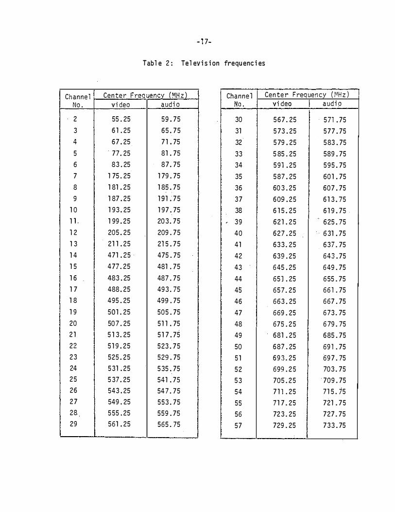
Tabl e 2: Tel evi s i on frequ enc i es
Channel Center Frequency (MHz) Channel Center Frequency (MHz)
No. video audio No. vi deo audio
2 55.25 59 . 75 30 5 6 7.25 . 571 . 75 3 6 1 .25 65 . 75 31 5 73 . 25 5 77 . 75 4 67 . 25 7 1 . 75 32 5 79 . 25 583.75
5 . 77 . 25 81 . 75 33 5 85.25 589 . 75 6 83.25 87 . 75 34 591 . 25 595 . 75
7 1 75.25 1 79 . 75 35 587 . 25 601 . 75 8 1 81 . 25 1 85 . 75 36 603.25 607 . 75 9 1 87 . 25 1 91 . 75 37 609 . 25 6 1 3 . 75
1 0 1 93 . 25 1 97 . 75 38 6 1 5 . 25 6 1 9 . 75. 1 1. 1 99 . 25 203.75 39 6 2 1 .25
"
625 . 75 , I
12 205 . 25 209.75 40 6 27 . 25 631 . 75 1 3 2 1 1 . 25 215 . 75 41 633.25 637.75 1 4 471 . 25 475.75 42 639.25 643 . 75 1 5 477.25 481 .75 43 645 . 25 649.75 1 6 483.25 487.75 44 65].25 655.75 1 7 488 . 25 493.75 45 657.25 661 .75 1 8 495.25 499.75 46 663.25 667.75 1 9 501.25 505.75 47 669.25 673 . 75 20 507.25 5 1 1 . 75 48 675.25 679.75 2 1 5 1 3.25 5 1 7 . 75 49 681 . 25 685.75 22 5 1 9 . 25 523 . 75 50 687.25 69 1 .75 23 525.25 529.75 5 1 693.25 69 7.75 24 531 . 25 535 . 75 52 699.2 5 703.75 25 537 . 25 541 . 75 53 705.25 '709.75 26 543 . 25 547.75 54 7 1 1 . 25 71 5.15 2 7 549.25 553.75 55 71 7.25 721 . 75 28 5 55.25 559.75 56 723.25 727.75 29 561 . 25 565.75 57 729.25 733.75

- 1 8-
Television frequencies (continued)
Channel Center Frequency (MHz)
No. I video audio I 58 735 . 25 739 . 75
59 741 .25 745 . 75
60 747.25 751 . 75 . .
6 1 753.25 757 . 75
62 759 . 25 763. 75
63 765.25 769 . 75
64 771 .2 5 775.75
65 777.25 781 . 75
66 783.25 787. 75
67 789.25 793. 75
68 795.25 799 . 75
69 801.25 805.75
70 807.25 811 . 75
71 813.25 I 817.75
72 819 . 25 823 . 75
73 825 . 25 829.75
74 831 .25 835 . 75
75 837.25 841 . 75
76 843.25 847.75
77 849.25 853.75
78 855 . 25 859.75
79 861 . 25 865. 75
80 867.25 871 . 75
81 873 . 25 877.75
82 879 . 25 883. 75
83 885. 25 889 . 75

-lg-
(iv) If the equivalent scattering area A� of the WT is different
from the Ae used in Table 1 , multiply each distance obtained in (iii)
by A�/Ae.
(v) (a) Choose cp, note cos cp.
(b) Identify the appropriate set of data, i.e., (a), (b),
or (c) in Table 3 and obtain y . Obtain y from Fig. 5 and 1 2 determine y = y1 + y2•
(c) From the given Ae' d and h3 identify Fig. 6(x) where x = a,b,
or c. From the given d, identify Fig. 7(x) where x = a,b, ... , or e.
(d) OVerlay Fig. 6(x) and 7(x) such that the y level of Fig. 6(x)
is at the 0 level of 7(x) with r = 1 of Fig. 6(x) at the r = Ieos <PI
position of Fig. 7(x). Read off from 6(x) the value of r at which
the f (MHz) curves cross, using the solid lines if cp < goo (dashed lines
if <P > goo) in Fig. 7(x). The result is r(cp).
(vi) If A' fA , multiply r(cp) of (vi) by A'/A . e e e e Repeat (i) through (vii) for all other Channels.
Steps {i) through (vi) complete the determination of r1, r2
and r(<P) for omnidirectional receiving antennas. With a directional
receiving antenna having a voltage polar diagram f(cp') such that
f(O) = 1, cp• = 0 being the direction of the maximum of the main beam,
(vii) multiply the r1, r2, r(cp) obtained in (i) through (vi) by f(cp') where cp• = 1 80° - cp.

-20-
8. A Typical TV I Assessment
In this secti on we use the TVI assessment procedure given above
to determi ne the i nterference zone of the MOD-1 WT on Channel 56 •11hose
transmi tter i s 75 km away.
The known parameters are :
vi deo a nd aud i o carrier frequencies of Channel 56 are (from Table 2)
723.2 and 727.75 MHZ
d = 75 km,
A9 = 40m2, Le = 25 m.
Proceed as fo 1 1 ows:
Method A
(i) Since the machi ne i s MOD-1 , use Tab1e l( b).
{i i ) Choose f = 700 MHz {A.= 0.43 m), d = 80 km a nd enter
Table l ( b) at (700, 80) to obtain
( i i i ) r1 = 4.6 km , r 2 = 5.5 km a nd, i f desi red ,
r ( 90°) = 4.0 km.
If the equi valent blade scatteri n g area of the gi ven mac h i ne i s
di fferent from that of the t100-l WT ( for example, i f A�/Ae = l/4),
then mod i fy the d i stances obta i ned i n ( i i i ) as follows :
(iv) r1 = 446 = 1 .1 5 km r2 = 545 = 1.38 km
r ( 90°) = 44° = 1 .0 km
Assuming A� = Ae = 40 m2 , obta i n the approx imate i nterference
zone as
( v) 0.01 7 (=1 .0°) rrL e = A. 183

-21-
backward interference region ( Eq. ( 2 ) ) :
r(�) = 4.6 cos t km
forward interference region (Eq. (3)):
r(�) = 5_5 sin(l83 sin �)
183 sin q, Method B (see Section A.3)
km ' 179° < ljl < 180°
(vi) See Appendix A for detailed calculations of r1,r2 ·and r(90°),
and for a more accurate determination of the interference zone using
the computer-graphical method.
Steps (i) through (vi) complete the assessment for an omni-
directional receiving antenna. With a directional receiving antenna
whose pattern f(�') is known, proceed as follows:
(vii) If the back-to-front ratio f(180°) = -12 dB � l/4, then
r1 = 44,6 = 1 .15 km r2 = 5.5 km (as in (iii))
approximate backward interference region:
r(�) = 1.15 cos ! km
approximate forward interference region:
same as in (v) above.

-22-
All interfe.rence distances in the backward region obtained in step
(vi) should be multiplied by f(180° - ¢}.
9 . A Note on the Smooth Earth Model
The calculation discussed above have been carried out on the
assumption of a smooth and homogeneous spherical earth, and it is
realized that local topography could increase or decrease the size
of the interference zone obtained in Section 7. Such effects are
particularly important when the wT is l 'ocated in a mountainous region
-where the ambient field strengths at the WT and the receiving sites
may differ significantl y from those computed using the smooth earth
model. It is therefore desirable to incorporate the effects of the
local terrain and/or the hills and other dominant features of the
terrain on the field strengths into the computer model. It is
understood that a computer program called RAPIT (Radio Propagation
over Irregular Terrain) is available [9].
10. Conclusions
Using results obtained from a computer program for ground wave
propagation over a smooth and homogeneous spherical earth, an
efficient graphical procedure has been developed for predicting the
zones of TV interference about a large �IT. The rough shapes of
these zones are similar for all horizontal axis machines but their
size increases with increasing WT height, blade area and TV Channel
number or frequency. The interference is therefore worst on the

-23-
higher UHF Channels and increases in severity with the size of the
machine. The observed interference effects depend significantly
on the quality of the receiving antenna. With a poor (omnidirectional)
or a wrongly oriented good {directional) antenna, any TVI effects in
a given situation could be pronounced, and under similar conditions
the backward interference would be dominant, implying r1 > r2•
However, with a properly oriented good antenna, the backward region
interference is reduced by an amount depending on the side and back
lobe characteristics of the antenna and the maximum interference
distance of a WT is generally determined by the. forward scattering
from the WT.
For the MOD-OA , MOD-1 and MOD-2 machines with metal blades, the
interference distances in three directions are tabulated at seven
frequencies spanning the VHF and UHF TV bands for five WT-transmitter
distances, and under most circumstances these parameters are
sufficient to define the entire zone. At other frequencies and/or
distances adequate accuracy can be obtained by linear interpolation of
the tabulated values, but if, for any reason, it is felt desirable to
compute the interference zone precisely, the graphs which are needed
to do this are included herewith. The method is such than an accuracy
of better than 0.2 km is achievable, particularly if a light table is
used in conjunction with transparencies made from the graphs.
The data which are presented are for the standardized heights
h1 = 300 m for the transmitting antenna, h2 = 1 0 m for the receiving
antenna, and h3 = 30, 45 and 60 m, corresponding to the tower heights
of the MOD-OA, MOD-1 and MOD-2 machines, respectively. For heights

- 24-
which differ substantially from these it is necessary to generate a
new set of graphs before proceeding with the interference calculations,
and we comment that the difference bet\lfeen h2 and h3 has a significant
effect on the level of interference observed. If, on the other hand,
the blade size and/or materials alone differ from the ones discussed
here, the graphs are still applicable, and it is only necessary
to change the equivalent blade scattering area Ae. For blades of
similar shape to those on the MOD-OA and MOD-1 machines the scattering
efficiency is approximately 0.65 and 0.25 for metallic and non-metallic
blades, respectively, and these values can be used to deduce the
equivalent area from the projected area.
The interference zone and the distances discussed here are for
the worst possible situation which generally occurs when the turbine
blades are so positioned in pitch as well as azimuth to direct the
maximum scattered signal to the receiving antenna. Depending on the
prevailing winds and the quality of the receiving antenna, some or
all parts of the interference zone could suffer interference only
for a fraction of the total time. Finally, we remark that the present
computer method based on radio wave propagation over a smooth spherical
earth requires modification to account for terrain effects.

-25-
Append i x A : Computer-Graph i ca l Method for Cal cul ation o f the I nterference Zone
A . l Theoreti cal Consi derati ons . The cal cul at ion of the
i nterference zones o f a WT i s based on the theoreti ca l express i ons for
the fi el ds der ived i n (2] and di ffers somewhat from th e procedure
u sed i n [1].
We cons i der a TV transmi tter (T ) at a hei ght h1 ( i n m ) above the
earth radi ati ng a hori zonta l l y po l ar i zed s i gnal wi th effec t i v e power P
( i n kW ) . The s i gnal impinges on a WT whose tower he i ght i s h3 ( i n m ) l ocated a d i s tance d ( i n km ) from the transmi tter , and i s al s o p i cked
up by a rece i v i ng antenna (R) at a he i ght h2 ( i n m ) above the earth
and d i s ta nce r ( i n km ) from the WT . The rece i v i ng antenna i s assumed
omn i d i recti onal a nd i n the abs ence o f the WT the di rect fi el d at R woul d co nsti tute the on l y s i gnal . The ro tati ng b l ade ( s ) o f the WT
sca tter some of the energy i nc i dent upon them and are the source o f
a s econdary s i gna l whi ch i s a l so p icked up by the recei v i ng antenna .
The rat i o o f the s econdary and primary s i gna l s at R i s the ampl i tude
modul at ion i ndex and , hence , a measure o f the i nterference produc ed
by the WT .
Th e a bove concepts can be express ed i n mathemati cal form as
fo l lows . The ampl i tude modul at ion i ndex o f the total fi el d at R i s
(A . l )
where ET(R) i s the ampl i tude of the primary fi e l d at R and E8(R) i s
the ampl i tude o f the s econdary fi el d wh i ch reaches the recei ver a fter

-26-
reflection off a rotating bl ade (B} o f the WT . The l atter fi eld i s
i tsel f the produc t of the d irect fi el d of amplitude ET (B) i l l umi nat i ng
the WT and the fiel d E8T(R) at the recei ver of a transmi tter of
effecti ve strength N 1 oca ted at the b 1 a de . �ole can therefore wri te
givi ng
m =
In practice, the hei ght h3 a t whi ch the bl ade scatteri ng occurs i s
usuall y different from the he i ght h2 o f the recei v i ng antenna, and
the ratio ET(B}/ET(R) wi l l then differ from uni ty for th i s reason
as wel l as .becaus e o f the d i s tance r of the receiving antenna from
the WT. It i s conveni ent to s eparate thes e two effects by wri ti ng
(A.2)
(A.3)
( A.4)
where B ' i s an 'equi val ent' bl ade l ocated at the WT, but at a hei ght h2
equal to that of the rec e i vi ng antenna . On i nserti ng this into (A.4),
we have
m = (A . 5)

-27-
The parameter N is determined by the scattering characteristics
of the blades. Laboratory and full scale tests and analyses indicate
[2,3] that the blade scattering is predominantly in the specular (mirror
reflection) and forward (blocking) directions, and is usually directed
towards the receiving antenna when the blade is horizontal. We can
therefore take the height h3 of the phase (scattering) center of the
blade to be the same as that of the WT tower. It is also found that
for machines such as the MOD-OA and MOD-1 having two fully controllable
blades, each blade contributes individually, whereas with the MOD-2
just a portion of the single blade is responsible for the largest
scattered signal observed. With both types of machine, the rotation
of the blades generates a periodic impulsive form of modulation. For
blades of large electrical size, the scattering can be estimated using
the physical optics approximation, and the calculation can be further
simplified by treating each blade as a rectangular metal plate whose
equivalent (scattering) area is Ae [3] .
Figure 1 shows the locations of the distant TV transmitter, the
receiver and the scattering center of a blade, all assumed to lie in a
horizontal plane, i.e., the plane of the paper. It is also assumed
that the blade rotates in a vertical plane through M-M (see Fig. 1 ) ,
and that this plane is so oriented as to direct the specularly reflected
field to the receiver. The parameter N characterizing a blade as a
re-radiator is then
N = N n (¢) 0 (A.6)

where
N = 0
-28-
A f e
r.::"p ' 4. 5 X 10⁴ v't-'
for 0 � I � I < 11' - All "' e
for 11' - A/le < 1�1 < 11'
( A. 7)
( A.8)
f i s the frequency (in MHz), le i s the effective l en gth ( i n m ) o f that
portion of the bl ade res po ns i b l e for the scatteri ng, and
s i ne x = s i n 11' x 11' X
Note that Ae cos •12 i s the projecti on o f Ae perpendicul ar to the
direction of i nc i dence.
If the pl ane o f the blade rotation i s al ways chos en s o as to
d i rect the maxi mum reflected or forward scattered fi eld to the receiver ,
� al s o speci fi es the angl e wh ich the l i ne RB ma kes wi th T B and, henc e,
the a ngul ar posi tion o f the receiver. N then achi eves i ts maximum
val ue N0 when � = 0 and 11', correspond i ng respecti vely to backscattering
off the b l ades (R i n l ine bet'.'teen T and B ) and forward scattering (R
o n the exten s i o n of TB). We now consi der the factors oth er than N on the ri ght-hand side of
(A.S). The rat io ET(B)/ET(B') i s obvi ous l y i ndependent of 9 and r, and
measures the change i n primary fi el d s trength due to th e differing
hei ghts of the blade ( i . e . , WT tower ) and the receiving antenna . It

-29-
is therefore a height gain factor which is rather easily computed for
any f, d, h1 , h2 and h3• The next factor ET(B•)/ET(R) is weakly
dependent on r. It is unity when r = 0, i.e., when the receiver is
at the WT tower, and remains·unity if the receiver is moved away from
the WT along the circumference of a circle centered on the transmitter,
i.e., for�= 90° . For a fixed r the ratio is an increasing function of
� ' being less than unity for 0 � � < goo and greater than unity for
� > goo, but if r is small the � dependence is relatively slight.
Finally, there is the factor EBT( R). This is a rapidly ·decreasing
function of r independent of �, and is the main source of the r
dependence of the right-hand side of (A.S).
As r increases, the right-hand side of (A.S) decreases, and a
procedure for determining the interference zone is now apparent. For
any given� ' r is increased until the threshold modulation index m0 (see Fig. 2 ) is attained. The resulting r then specifies the radius
of the interference zone in that direction. If the value of r so
obtained is fairly small, e.g., s 1 km, most of the � dependence is
provided by the factor N, and the slight dependence that ET(B•)/ET(R)
provides is, in part, cancelled by the variation of the threshold
modulation index m0. In this case the zone has the shape indicated
by n(�), i.e., is a cardioid plus a forward spike, and a knowledge of
r in just two directions, one in the forward part of the zone (i.e.,
� = 180°) and one in the backward part, e.g., ¢ = 0 or goo, is
sufficient to establish the entire zone. Unfortunately, this is
not true if r is larger.
-30-
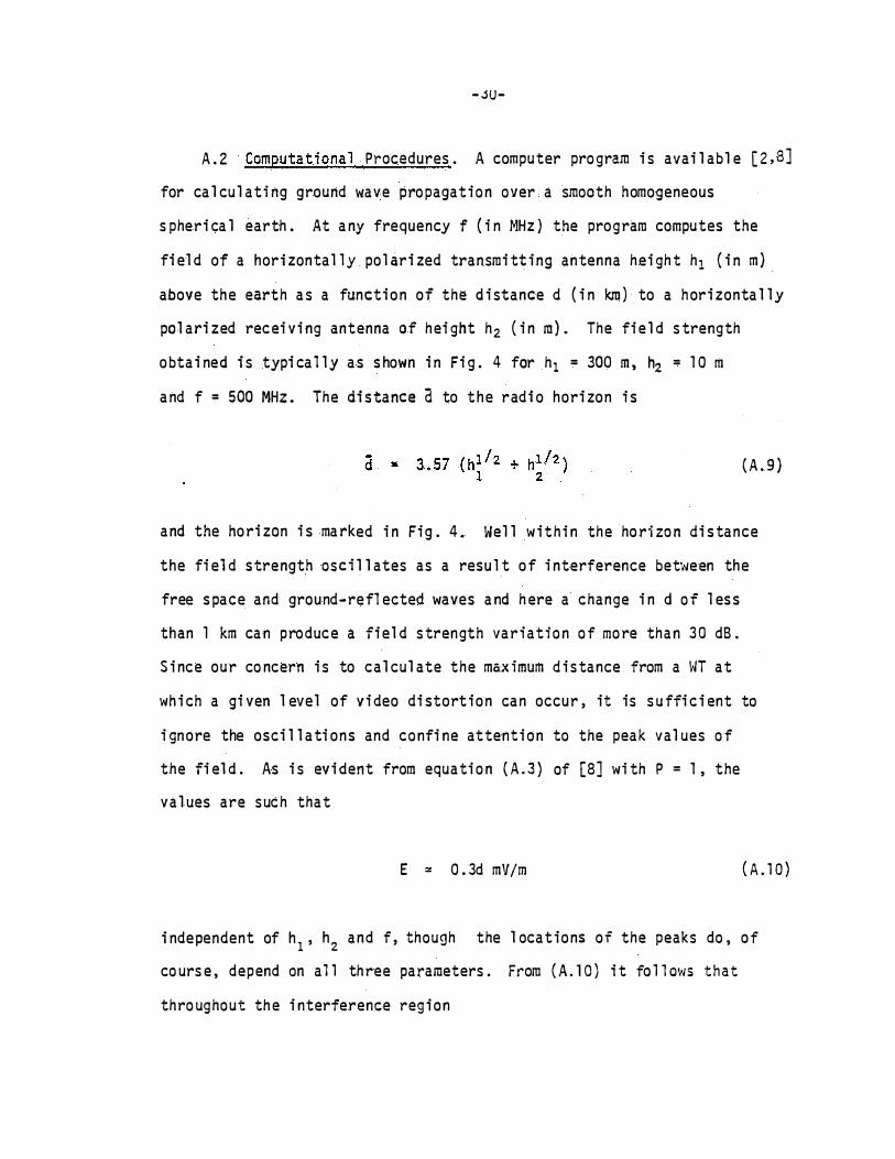
A. 2 Computationa l Procedures . A computer program i s avai l abl e [ 2 , 8] for ca l cul ati ng ground wave propagation over a smooth homogeneous
spheri ca l earth. At any frequency f ( i n MHz ) the program computes the
fi el d of a hori zontal l y pol ari zed transmi tt i ng antenna hei ght h1 { i n m )
above the earth as a function of the d i stance d ( i n km} to a hori zonta l l y
po l ari zed recei vi ng antenna o f hei ght h2 ( i n m ) . The fie l d strength
o bta i ned i s typi ca l l y a s s hown i n Fi g . 4 far h1 = 300 m , h2 = 1 0 m
a nd f = 500 MHz . The di s tance a to the radi o hori zon i s
( A. 9 )
and the ho ri zon is ma rked i n Fi g . 4 . Wel l withi n the hori zon di s tance
the fi el d strength osci l l ates as a result o f i nterference bet\<Jeen the
free s pace and ground-refl ected waves a nd here a change i n d of l es s
than 1 km ca n produce a fi el d strength variation of more than 3 0 dB .
S i nce our concern i s to cal cul ate the max imum d istance from a WT at
wh i ch a gi ven l evel of vi deo di stortion can occur, it is suffi ci ent to
i gnore the osci l l ati ons and confi ne attenti on to the peak val ues of
the fi el d. As i s evi dent from equati on ( A . 3) of [8] wi th P = 1 , the
val ues are such that
E = 0.3d mV/m ( A . 1 0)
i ndependent of h 1 , h2 and f, though the l ocations of the peaks do , of
course , depend on a 1 1 three parameters. From ( A . 1 0 ) i t fo 1 1 ows that
throughout the i nterference reg i o n

, , '
- 31 -
20 log E = - ( 1 0 . 46 + 20 l og d) ( A. 1 1 )
and the corresponding straight line is indi cated in Fig. 4 .
The field strength program is the basis b f our method for
computing the interference zones about a WT. It is assumed that the
equivalent ( blade) scattering area Ae and the tower height h3 are
known for the WT in question, and all calculations are carried out for
a transmitting antenna o f height h1 = 300 m and a receiving antenna of
height h2 = 1 0 m, typical o f the values encountered in practi ce. Since
the effective radiated power P plays no role in our analysis, we
henceforth set P = 1 .
The following computations are performed:
( i) field strength as a function of distance r ( in km) for a
transmitter of height h3 and a receiver of height h2 = i O m at 7
frequencies spanning 50 � f � 900 MHz, from which plots of 20 log E8T( R)
vs. r are constructed ;
( ii) field strength of a transmitter of height h1 = 300 m at a
receiver of height h3 at a distance d = 20 ( 20 ) 1 00 km away at the same
seven frequencies ;
( iii) field strength of a transmitter of height h1 = 300 m at a
receiver of height h2 = 1 0 m distance d ± r a�:tay for the s·arne va 1 ues
of d and the same frequencies as above, with incremented values of
r up t o ( say) 1 5 km .
In all cases the actual field strengths in the interference region
are replaced by those deduced from ( A.ll).

- 32-
The second set of data i n conj unction w i th the th ird for r = 0
gives ET( B ) /ET{ B ' ) at seven frequencies and fi v e WT-to-transmitter
di stances d . The rat i o i s just the hei ght gain factor associ ated wi th the di fferent receiver and WT tower heights. For the val ues of h3 of concern to us it is found that if d � 1 00 km the ratio is
virtual ly independent of d and can , in fact , be obtained from an
analytical expression for the hei ght ga i n factor appropriate to the
deep shadow reg i on [10] . When normal ized to the val ues for r = 0 ,
the th i rd set of data then yiel ds plots of 20 l og ET( R) /ET( B ' ) vs . r ,
repres ent i ng the dB attenuation as a function of the distance r of the
receiver from the WT·. Far d > 100 km the attenuation is a 1 so independent
of d to a first approximation and can be determined analytical l y [ 1 0 , 11 ] .
A graph ica l method for cal cul ati ng the interference zone about
a WT i s as fo l l ows . From (A . S )
( A . 1 2 )
where
( A . l 3 )
with
m (0) E;( B ' ) yl = 20 l og 0 ( A . 1 4 ) � E ( B )
and m (<�> )
y2 :: 20 l og 0 (A . 1 5 ) m0 (0 )n(rp )

- 33-
Knowi ng Ae for the WT bl ade , N0 can be computed ( s ee (A . 7 ) wi th P = 1 )
at each o f the chosen frequenc i es . From ( i i ) and ( i i i ) a bove w ith
m0 (0 ) = 0 . 1 5 ( s ee Fi g . 2 ) , a tab 1 e i s then com pi 1 ed showi ng y1 for
a l l comb i nat ions o f the fi v e ra nges a nd s.eYen frequenci es as s hown
i n Tab l e 3 . Al s o , from Fi g . 2 and the equa t i o n ( A . 8 ) for n ( � ) , y2
can be computed for any � . 0 � � � 1 80 ° . The res ul ts are i ndependent
of d and ( fo r a l l practi cal purposes ) f and the pa rti cul a r WT , and
are pl otted i n Fi g . 5 .
To compute the i nterference zone o f the WT for s ome s pec i fi c
TV transmi s s i o n , the g i s t o f the method i s as fo l l ows . Knowi ng the
actua l frequency ( see Tab l e 2 to convert TV Channel number i nto
frequency ) and the WT- transmi tter d i s tance , we use the data for the
c l os es t frequency f ( i n MHz ) and d i stance d ( i n km ) . By a ppro pri ate ly
overl ayi ng gra ph s o f 20 l og EBT
( R ) and 20 l og ET ( R ) / ET ( B ' ) vs . r ,
i ntercepts o f correspo nd i ng curves are fou nd , and thes e g i ve the zone
rad i us r( � ) for any des i red azimuthal l ocat ion � of the rece i ver wi th
res pect to the WT- tra nsmi tter d i recti on . The proc edure is i l l us trated
i n the next s ec t i o n and i f greater accuracy i s n eeded , resul ts can
be o bta i n ed for frequenc i es and d i s tances on both s i des o f the actua l
o nes , and l i near i nterpo l ati on empl oyed .
In comput i n g the i nterference zone the effect of us i ng a
d i rect i onal anten na can be taken i nto account as d i scus sed i n Sec t i o n 6 .
In the express i o n (A . 1 5 ) for y2 , d i v i de the funct ion m0 ( � ) by f ( � ' )
where � · i s now the angl e b etween the d i rect i o ns to the transmi tter
and the WT as s een from R ( approximatel y 1 80 - � for d >> r) . The
- 34-
resul ts of th i s o perati o n are i l l us trated i n [4] where the i nterference
by the HO D-OA machine o n B l ock I s l and is examined .
A.3 Speci fi c Computati ons. Our ma i n concern is wi th the MOO-OA ,
M00-1 and MOD-2 machines whose tower hei ghts h3 wi l l be taken as 30 ,
45 and 60 m res pecti vel y . An impo rta nt parameter a ffecti ng the
i nterference i s the equi val ent scattering area A9 of a bl ade. Th i s i s
rel ated to t he projected geometr i ca l area AP v i a the scatteri ng
effi c iency n such tha t Ae = nAP
, a n d the projected areas o f the
MOD-OA and M00-1 b l ades are 1 8 and 62.5 m2 res pectivel y . From
l abo ratory model and ful l scal e scattering tests [3] the scatteri ng
effi c i enci es of these metal bl ades were "fo und to be 0 . 67 and 0 . 63
res pective l y , implyi ng Ae = 12 and 40 m2 for the two mach i nes. For
a MOO-OA bl ade o f fi bergl ass cons truction wi th a mi n imal co n figurati o n
( stage #2 o f [3] ) - of l ightn ing arrestor stri ps , the correspondi ng
s catteri ng effi c i ency is 0 . 27 , so that Ae = 5 m2 approx imate l y . Thes e
val ues of n and Ae are a l so appl i cab l e to the corres po ndi ng wooden
b l ade.
I n the case of the MOD-2 mach i n e , measurements o f the scatterin g
from a sma l l scal e model bl ade show that t h e l argest scattering i s
provi ded by a centra l sectio n of the b l ade of a pprox imate l ength 6 3 m,
and the equ ival ent scatteri ng area impl i ed by th i s i s A = 1 40 m2 • e
The re l evant parameters for the three machines wi th metal b 1 ades
are then as fol lows :

- 35-
h 3 (m)
MOD-OA 30 1 2 1 5
r�OD-1 45 40 25
MOD-2 60 1 40 6 3
Tab l es 3 ( a ) through ( c ) on pa ge 3 8 l i st y 1 ( s ee (A. l 4 ) ) for these
mach i nes for f = 1 00 , 200 , 300 ( 200 ) goo MHz and d = 20 ( 20 ) 1 00 km .
Th e fol l ow i n g gra phs are needed to compute the i nterference
zones , and are presented i n the fi gures c i ted .
20 l og E8 ( R ) vs r for the s even frequenc i es and the three
tower he i ghts l i s ted above : Fi gs . 6 ( a ) through ( c ) .
20 l og ET
( R ) /ET
( B 1 ) vs . r fo r the s ev en ·frequenc i es and the fi ve
WT- transmi tter d i s tances d = 20 ( 20 ) 1 00 km : Fi gs . 7 ( a )
through ( e ) . For a recei ver cl oser to th e tra nsmi tter
than th e WT , i . e . , 0 � � < go o , the appropri ate curves
are s hown as so l i d l i nes , whereas fo r go o < � � 1 80 °
the l i nes are broken .
To i l l us trate the procedure , cons i der th e computat ion o f the
i nterference zone for a MOD- 1 WT on TV Channel 56 whose transmi tter i s
7 5 km away . From Tabl e 2 the c l o s es t frequency for wh ich curv es are
provi ded is 700 MHz , and the c l oses t va l ue of d is 80 km , imp lyi ng
Fi g . 7 ( d ) . From Tabl e 3 ( b ) the appropr iate dB l evel y1 is then - 28 . 1 .

-36-
1 . � = 0 . S i nce y2 = 0 , y = y1 = -28 . 1 . Overl ap Fi gs . 6 ( b ) and
7 (d ) pos i ti on i ng the -28. 1 l evel of Fi g . 6 (b ) at th e 0 l evel
of Fi g . 7 ( d ) . Read off the va l ue of r at wh i ch th e 700 MHz curves
cross , us i ng the sol i d l i nes in Fi g . 7 ( d ) . The resu l t is r ( O ) =
4.6 km .
2 . ¢ = 1 80 ° . Fi gure 5 g i v es y2 = 7 . 4 . Henc e , y = y1 + y2 = - 28 . 1 +
7 . 4 = � 20 . 7 . Overl ay Fi gs . 6 ( b ) and 7 ( d ) , pos i ti on i ng the
-20 . 7 l evel of Fi g . 6 ( b ) at the 0 l evel o f Fi g . 7 ( d ) . Read
off the val ue of r at wh ich the 700 MHz curves cro s s , us i ng the
dashed l i nes i n Fig . 7 ( d ) . Th e resu l t is r ( 1 80 } = 5 . 5 km .
3 . � = 90° . Fi gure 5 g i ves y2 = 5 . 5 . Hence , y = y1 + y� = -28 . 1 +
5 . 5 = -22 . 6 . Us i ng Fi g . 6 ( b ) a l one , read off the val ue o f r
at whi ch the 700 MHz curve crosses the -22 . 6 l evel . Th e resul t
i s r ( 90 ) = 4 . 0 km .
Under mos t ci rcumstances the approximate shape o f the
i nterference zone is known , and the ent i re zone is then determi ned
by the val ues of r ( O ) , r ( 1 80 ) and , perha ps , r ( 90 ) . However , i f
greater accuracy i s requi red , r ( ¢ ) can be computed for any desi red
¢ u s i n g the above-mentioned graphs . The approach is based on the
fac t that for • F 0 the d i s tance o f the recei ver from the transmi tter
is approximatel y d-rcos ¢ and not d-r . The manner i n wh ich th is
a ffects the computat ion o f r ( ¢ ) for ¢ F 0 , 90 or 1 80° i s i l l ustrated
by the fo l l owi ng exampl e .
-37-
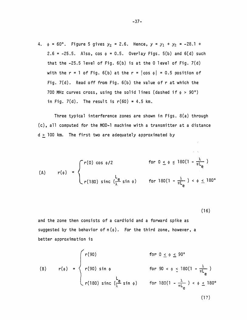
4 . � = 60° . Fi gure 5 g i ves y2 = 2 . 6 . Hence , y = Y1 + Y2 = - 28 . 1 +
2 . 6 = -25 . 5 . Al so , cos � = 0 . 5 . Overl ay Fi gs . 5 ( b ) and 6 ( d ) such
that the - 25 . 5 l ev el of Fi g . 6 ( b ) i s at the 0 l evel of Fi g . 7 ( d )
wi th the r = 1 of Fi g . 6 ( b ) a t the r = I eos � � = 0 . 5 pos i ti on o f
Fi g . 7 ( d ) . Read o ff from Fi g . 6 ( b ) the va l ue o f r at which the
700 MHz curves cros s , us i ng the sol i d l i nes ( dashed i f � > 90 ° )
i n Fi g . 7 ( d ) . The resul t i s r ( 60 ) = 4 . 5 km .
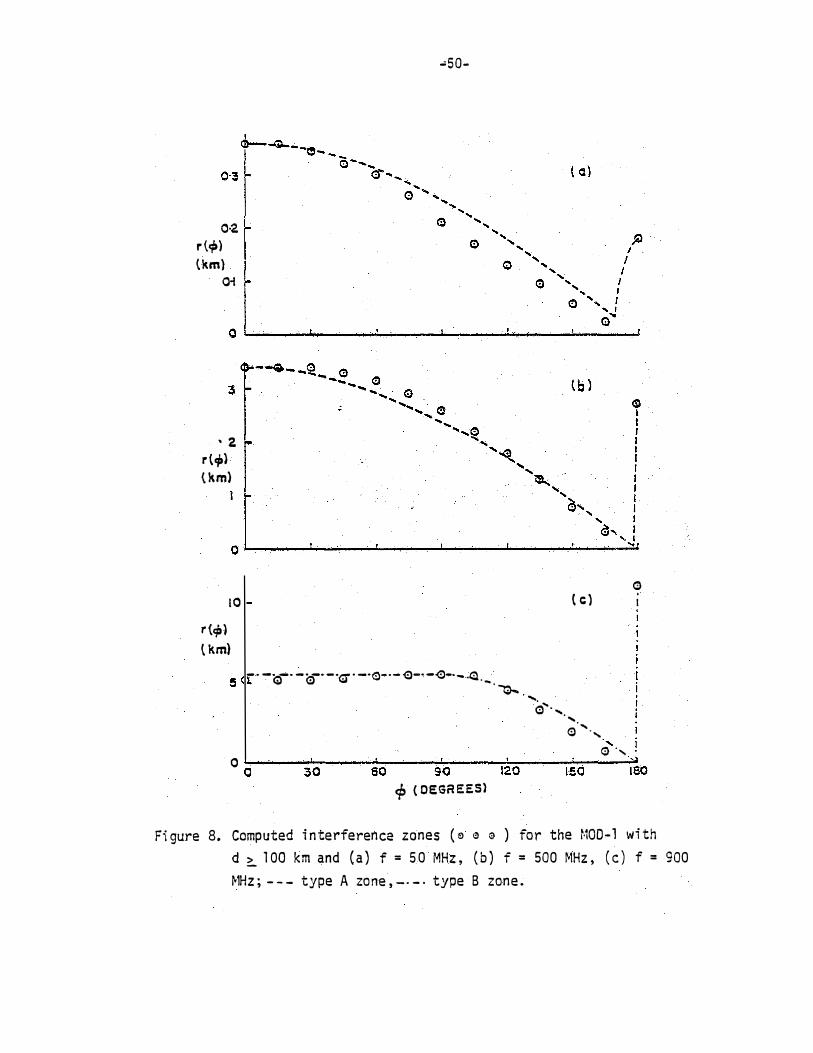
Three typ i ca l i nterference zones are shown i n Fi gs . 8 ( a ) through
( c ) , a l l computed for the MOD-1 mach i ne wi th a transmi tter at a d i s tance
d > 1 00 km. The fi rst two are adequatel y approx imated by
( A )
-- { r ( O ) cos �/2
L r ( � )
r ( 1 80 ) s i n c ( A. e s i n � )
for 0 � � � 1 80 ( 1 - 'ITt ) e
for 1 80 ( 1 - __ A. __ ) < � < 1 80° 1TL e
( 1 6 )
and the zone then cons i sts of a card i o i d and a forwa rd sp i ke as
suggested by the behavi or of n ( � ) . For the th i rd zone , however , a
better approximat ion i s
r ( 90 )
( B ) r ( q, ) = r ( 90 ) s i n q,
L r ( 1 80 ) s i ne (
A.e s i n � )
A. for 90 < ¢ � 180 ( 1 - - ) - 1TL e
for 180 (1 - __ A.
__ ) < q, < 1 80° 1T le
(17 )

- 38-
Both s hapes are compl ete ly s peci fi ed by a knowl edge o f r ( O ) , r ( 90 )
and r ( 1 80 ) , and the rat i o r ( 90 ) /r ( O ) can serve as th e bas i s for the
cho i c e of shape . The rat i o i s 0 . 71 for type A and 1 fo r type B , and i n
those rare cases where i t substanti a l l y exceeds un i ty , nei ther
approx imation i s good . A preci s e determi nati on of the i nterference
zone i s then des i rabl e .
The computed i nterference zone radi i r ( O ) , r ( 90 ) and r ( 1 80 ) fo r
the MOD-OA , !100-1 and MOD-2 mach i nes wi th metal bl ades are sho\'ln i n
Tab l e l(a ) through (c ) for f = 50 , 1 00 , 200 , 300 ( 200 ) 900 MHz wi th
d = 20 ( 20 ) 1 00 km . Except pos s i bl y a t the h i ghest frequenci es for the
l arger d the zones are of type A, but i n the case of the MOD- 2 machi ne
there are a few i ns tances , e . g . , f = 900 MHz wi th d � 60 km where even
the type B s hape does not prov ide an accurate a pproximati o n .

- 39-
Tab l e 3 : dB · l evel y1 ( s ee equat ion A . 1 4 )
( a } MOO-OA (Ae = 12 m2 }
f(MHz } 20
50 11. 7
100 6 . 4
200 4 .0
300 3 . 4
500 1. 3
700 -1. 5
900 -3. 7
(b) MOD-1 (A = 40. m2 ) e
f(MHz ) 20
50 -2.0
TOO -6 . 2
200 -6. 5
300 -7.1
500 -9 . 2
700 -11. 9
900 -14 . 1
40
11. 5
5 . 5
-0. 3
-3. 6
-6 . 2
-5.9
-6. 1
40
-2. 4
-8 .3
- 13 .8
-16.7
-16 . 2
-16.4
-16 .6
(c ) MOD-2 (Ae = 140 m2 )
f(�1Hz ) 20 40
50 -14 . 9 -15 .8
100 - 1 7 . 3 -21. 5
200 -17 .4 -26 . 5
300 -18 . 0 -28 . 2
sao -20 . 0 -27 . 5
700 -22 . 8 -27. 2
900 -25.0 -27 .4
d ( km}
60 80 !_100
11 . 5 11 . 3 11. 5
5 .4 5 . 4 5 .3
-1 . 0 -1. 0 -0 . 9
-4. 5 -4 . 8 -4 . 6
-8 .a -9 . 6 -9.5
-11 .7 -12 . 9 -12 . 8
-13. 7 -15 . 5 -15 .3
d (km )
60 80 >100
-2. 5 -2 . 7 -2.6
-8. 7 -8. 7 -8 . 8
-15 . 2 -15 . 3 -15 . 3
-18 . 6 -19. 2 - 1 9 . 2
-22 . 8 -24 . 4 -24 . 4
-25 . 2 -28. 1 -28 .1
-26 . 5 -31 . 0 -30.9
d ( km )
60 80 >100
-16.0 -16 . 2 -16 . 1
-22.1 -22 . 3 -22. 4
-28. 7 -29. 1 -29 . 1
-32 . 0 -33. 2 -33. 2
-35 . 7 -38 . 7 -38. 9
-37.1 -42 . 6 -42 . 8
-36 . 7 -45 . 7 -45."9

2 10 10 3 d {ltm )
Fi gure 4 . Fi el d s t rength i n dB above mv/m a s a funct i on of di s ta nce d from a hori zontal ly polari zed
transm it te r radi at i ng l kw e ffect i ve po�Jer : h 1 = 300 m, h2 = 1 0 m , f = 500 Ml1z .
I .p. 0 I

i' I
20
15
·- · - · - -- - - --- -
. .; __ 10
5
- 41 -
. - - - - - - - .. - . .. --· · · - . -··--- . .
- . -· · ·· -
-- - - .
-·- - _ _ :__( ---
- ---�
-- - - -- - - - --- - -- - - - ----- -· -- ------ ----- - ·-· - - - -- -- - - -- - - - . . - --- . ..
.•. . . . ..
· - -
-- -- ------- - -- . ----- - ---- ·-------- -·· - ---- - ···- · ·
- --- -- · -· ... - - -- - - - --
0 ��--------�------------�----------� 0 60 . " 120
- cp ( DE G REES) -- --- -
-- . .
Fi gure 5 : dB l eve l y2 versus • ( s ee equati on 1 5 ) .
I SO

0.2 r ( km) tOO
Fi gure 6 ( a ) . Fie l d s trength [EBT( R) ] i n dB above mv/m a s a funcfion of d i stance r from a transmi tter
l ocated at the HT b l a de phase center and radi a t i ng 1 Kw e ffecti ve power : h2 = 1 0 m ,
h3 = 30 Ill H10D-OA)
, . . ,. N I

'
I I I ; .
I" i"' �
- It
0.2
I r ,[lmrrfllii�IIILII[III[.I[.f l l l l l l l l lr , , .. i r , I ·�I I �� . .. �· "'�Ill"' n I I I ' I II II I iillll ' 1lTfll1TI1DmnTimlll l I I I I . ; I I
·IIII I� Ill I I I I I ! 1 1 1 1 1 1 111111 IUU.IIIJ.IU+H+I-J+I.I.Hm� ill td�·-� -·
N
1:1.1 r ( k m l
K � _ mN.ufl l l llil5:j
�
��- ·-J\. _ , _
Is 10 1 0 0
BT ' · ' · : : , , : '� ;_ Fi gure 6 ( b ) . Fi el d strength [E ( R ) ] i n dB above mv/m as a functi on of d i s tance r from a transmi tter
l ocated at the �JT bl ade phase center and rad iat ing 1 Kw e ffecti ve power : h2 = 1 0 m ,
h 3 = 45 m {r·10D- l)
I ...,. w I

· - ·
0. 2 1 r ( km l 1 0 1 0 0
- Fi gure 6 ( c ) . F i e l d s trength [EBT ( R ) ] in dB above mv/m as a function of d i stance r from a transmi tter
l ocated at the WT bl ade phase cente r a nd radi a ti ng 1 Kw effect i ve power : h2 :::: 1 0 m , h 3 "' 60 m ( �100-2 )
I .j::. � I

- � W ... U. .:D :-.1 0. � - W foo Ul CR ..... '* 'A
,1-r-r-r-,rrrrrrJh-n-rrn-rrhrrr
- .. � � •• m � � f"' JQ
.· .. . . I I I I I· .
· . . . 'I ' ' ' d •, : . I ' ' I � I !' I
- � - I I . � .- - � - I I 1 � � · 'r - · · 1 I 1 1 i 1 ' 1 : - - -- . , .
- . r � . . I ' · I - ' - -
· · I - -- - - · , , 1 zf4,.t : ,
-� =- :· -
I . I ' . · -� I I !1(('k'�! . . } ' ! 1 1 I '
• . . I i I I I . I I ���� ; I ' I ' I I I ' I
, , . I . . � �� ��� .
. l • � I I( i ni . I I . I I � � �: .
I i - -_- . - . - � .
1 • . . . ,!_ _. I -I ' Ill - � :. . � j _ -
. - - . I ll ' I
l ifi! .- · :.-. ..
- . I
.. _ _
1 , I · ' �,: �r, P� 1 • ll+tttmHii I
. � . - : Ill-
-- - d. I I ,
- . * ' I I ' - I I I, I I I I l - - - - - II . , !I r ; , I I i I ' ' .... 1 1 r ·
. · 1 1m. ' 1 . · , , · � = � �.� - t · 1 · , 11 - : -. . l III II' I . -.- .. .- ·. I� .)�
.
I I � = : : . I I ' ·,: ,1! I I · ' I ' -- . . • I ...: _ _ � _. _ - . - - Jr: :-- -= -- - - . - - -
. ; . · I f· l j f:,! _� :� �·� - · . ,. , . � �i, oo· ·.· , !I , ,. ,� ,� .
I - I I I l II . ' - . , , I I I I ! I : I t ' . I I--t-t
.. -++, � ·�I .. E-1. I � = : ' I I, i l l ! ' i j ·1 lji I ! ' .- : . . i 1 1 ] 1 I [ ,l ! ' · ' · 1 1 ! !
' ' . I - - - .. tl ' I 1 , , , I II I I ; I l l •. - .. - . ,, I I I h ; I i ! 1 ' 1 I f--,��- l- - - · 1 - - 1 :� � � - � �, - , f 1 T 1n1 -� 1� , � � 1 :� � = � , l'T lm· n � � 1 rr r� � ��� - 1 l l i '-'-1-.J....LJ:�:.J::J..U� . ! ' I - - .. . H II 1111 i l ' ll ,,dlll - - - '
I I I I l llil l l i !II I .! ·II'
r ( km)
Fi gure 7 ( a ) . Rat i o of the di rect f iel d s trengths at the recei ver ( R ) and WT bl ade phase center ( B ) [E1( R }/E1( B ) ] i n dB as a functi on of the d i s tance r from the HT : -- 4> = 0 ;
_ _ _ _ _ _ 4> = 1r . d = 20 km.
0
I -"" Ul I
- w • •• 0> ..,. ����o oa - N .... O• � .,. · • "' •u a
.... r w .. ... :-.& � ·•
r n, u l m i� I� �� �,!-.--_ , ,.......-,-,-1 1m '1_111-r MT<T"n"ll ! II 00 ���� 1 n j! 1�1 � I ilji !iii ii i - I l l .,· , r -, l"i l l l llll l,l'i !ll ! -f - - 1-l r - , I
l l, · ,ll I I I� ����� � T.rr ' ] ' '' � I l l"� l',i ii l - . I I ' I I : l Ur· j !Ill - - I ' l ,J·I · ,y · • . ill·mi' :lll 4-r - I I 1 � � � � � � � I - T ' I I �-�� I ' • ,I " f ll llldrl·; , ' ; I : 'I I I I . r I I . ', ,ul! ;
I I I II' l ' k . I ' :I I I I , , ! - I I , I I jl :i'! ,. - . I , jli 1 ' di : 1 1 ·111 - - - - - i 1 1 1 ,.1 1· - - - - - 1 · 1 1 1 .u: 1• , ;-. - r t l t ' 1 - nn 1' 1 '' 1
I
' 1 ' 1 ·11 - I t i i Wi :".t� t+t l' 1 1 1 1 1 i I IJ ! I' I I i , !' - - - - - - II I I � ���j - � -. - - - I l ll�!t - . ! I ' :�- : � � fi r �� -� 1 ltd l t 11 I � � � I i ll h ; - . I f'H flli II . I ' L I I 11 ' I I I '' 1!11111!1 :; ·
- .1 - - 1 ; • ![: �t-J· - - . . : · -1 ' � !' m,�� l q . 1 1 11 1 i i r · 11 .1 1 - r . ,,lllllll I� - - -l i d' �r- - I I ill I i J i i'· ii.�� �: I II ( I ' I l l -� . . l i - ·1 ,, ,,,,,, 't1-t ,- 'I , ,. I j �;,l 1 I jdj l l1,·L . . � .Il l �, 1!11 � I I'l l' ',· I 1
1
l
1 'tN r 1 1 ' '1 - r-l, � · ' 1 i 1 I ll - I I 11111!11 - - - - ' ,r- - .-- · r ! l , u · I ! l l !l( ·� - - -r++'- :�. , ,. , I l l ' ! l j
I -j l I
I ����� - : I I ��I n;} II I ij I' ,. ,I ll � : t . . I ��
- - 111111�11�· ��· : I I · I ' I , . ! ; - = f · II� �':·� · I � � ! � -· :.- .! -I I I 'j· . { I I I I II '
- - - - I ' I l l I I I I ! I - - - - !ffi - � I · '!'' ' ' -· - - if:=! i I I ' I ' I I I ;�! i 1 • I' 1 1r .1� r l 1 �, . . � 1 ' , 1 . 1 _, , 1 , I 1 1 , , 1 . I , - -H -"i;; � I � I ( I I , , !�{ > � - t . l I �� f !II rj I I ' II ' -_- l Jt -l i. I l -l{ iili lir' r I· l l 'l 1[1· 1 ! '1 .,: u j ' l l l � 1 1 1 J � ,j - · I I I j ,:II:. ! I JI I 1 1 1 1 1 . : . 1 ! l iJ I I l l · l ' ! l j : i · i · l ' · ' : l l l i' l l +I -�_i 1 , , , , ,. 1 �1 , .,, - - -- - T . , 1� � ���� - l· hl: : 1 li1l �,�� �!.� -_ - - - - - r-'-� � 1·1 , 1, ,1 wl nti i l il �1ll . . , l l lLL � � J !1:.1 l 1 I ! !! · · l I ; f11J Jlll l 11 1illlil ! �! . . . ! ! 1 . 1 I � : , ill! 1 ! 1 ! l 1 i ! k 1:�! ��:�
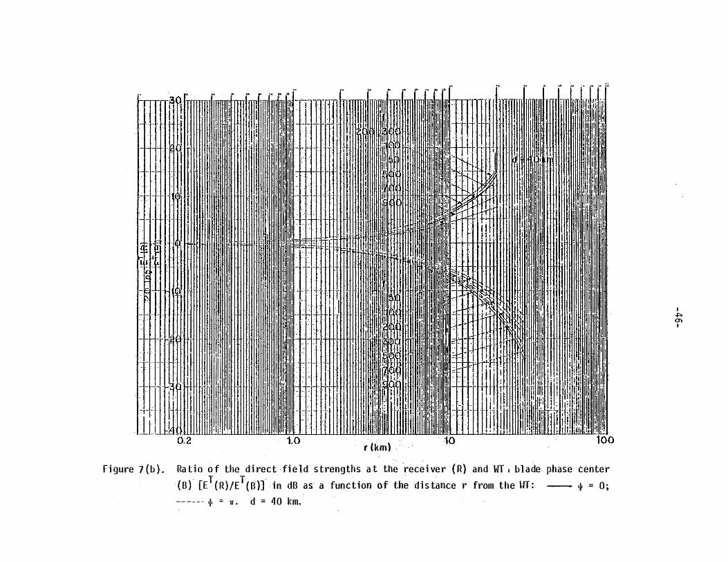
r (km) fi gure 7 ( b ) . Ra ti o o f the di rect fi e l d strengths a t the recei ver ( R ) and WT . bl ade phase center
( B ) [ET( R )/E
T ( B )] i n dB as a function of the d i s tance r from the HT : - 111 = 0 ; -- -- - - 4• = 11 . d = 4 0 km.
\,
I """ (})
I
I" l"' I" � ' r - - - -- r � � r J �Q· • •••IItltlllnrmrld,ntlnn uulrmlm..l--rt 1 1 1 l l l t l a i l illliillltlllll�l r t idllllhmtr
tlllll�mmml�llllllll�ll :.l: l ·l�l l l l l l ltiffi�1111llil�•��:-
�lttti�HHffillllll' . . .. . . .. . . . . .. . . . ........... . ·��""" . . . . .. .... .. . . . . ........... ! ' . 1 . 1 1 1 Ll l l l l l l l l l l l l l l l l lll l lll l l l l l l l l l l l l lllllllllill!llll I I I I I I I I I I I I I I I I I I II I I IIIII!II I H I I I I I I I I I I I I IIflliltH:JiiL
@ 1 -l ll rfii i i i i i i i i i i i i i ii i i i ii i i i ii ii i i i i ii i i i i i ii!I IIIIIIII · I I I I I I I I I I I II I I I IIII I I I I I I I I IIJ!;IIN J.UHttmlllllllllllllll ,:,
... .
ID�IW�II -�: -� R I I � :, : :,_,
0. 2 1 .0 r ( km) 10
I" :- i
II ; r�� 100
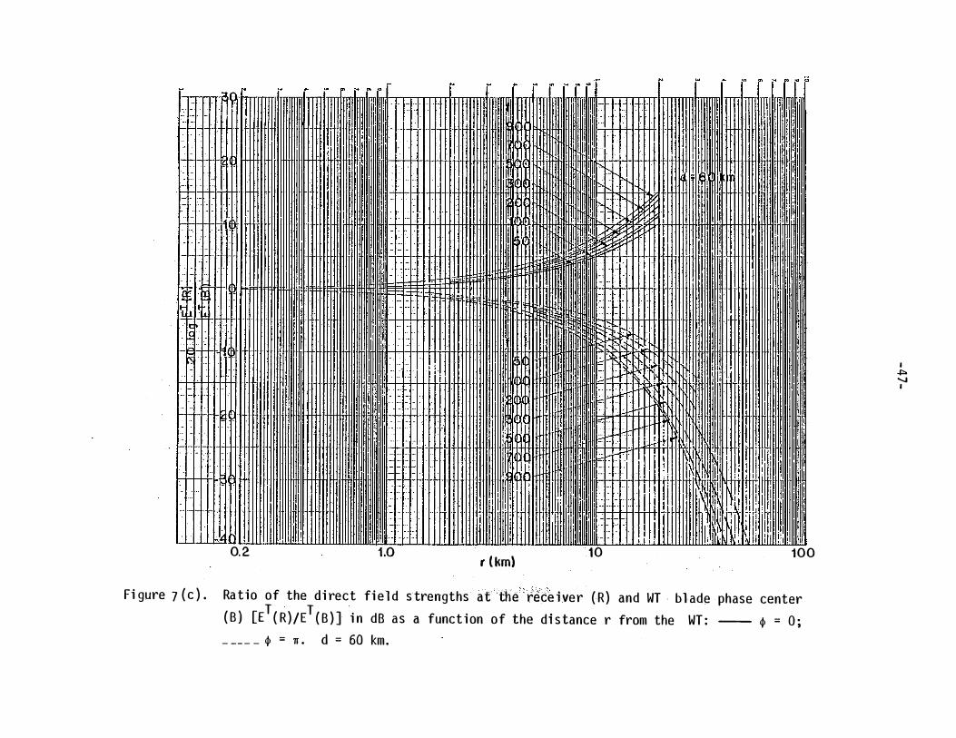
Fi gure 7 ( c ) . Ra tio of the d i rect fi e l d strengths at the - rece i ver ( R ) and WT . bl ade phase center ( B ) [ET ( R )/ET ( B ) ] i n dB as a funct ion of the di s tance r from the WT : ----- � = 0 ;
_ _ _ _ _ � = 1r . d = 60 km.
I � ...... I

0. 2 1.0 r (km) Fi gure 7 ( d ) . Rat io o f the di rect fie l d s trengths a t the recei ver ( R ) and WT bl ade phase center
( B ) [E1 ( R ) /ET ( B ) ] i n dB as a func tion of the di s tance r from the 14T : -- �� = 0 ; _ _ _ _ _ �� = n • d = 30 km.
I ·�"> CX> I
t" I" �
�·-!= R
0. 2
i 1 1 111111
1 · ··-
il · • ·
' II II" . . -I i i i · -· -· · ·
1.0
f' :-
r (km)
� � ' '
t-- I� � ""
10
I" ' i" o- i r' P
1 1 1111 1111
I i fl
!J 100
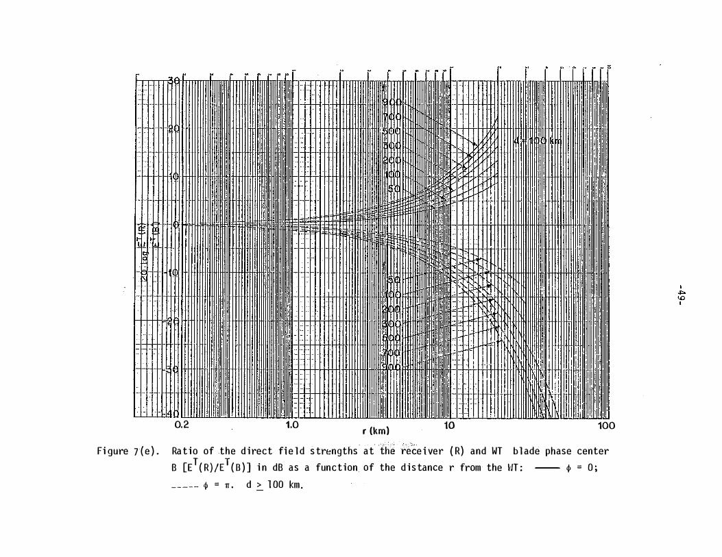
Fi gure 7( e ) . Ra t io of the d i rect fi e l d s trengths at· th� rece i ver ( R) and WT bl ade phase center B [ET( R ) /ET ( B ) ] i n dB as a function of the d i s tance r from the HT : -- � = 0 ; _ _ _ _ _ � = n . d > 1 00 km .
0·2 r (�) \km}
0-i
' 2. r (cp) { km}
10
r {cp) { km)
-so-
• - · -�· - ar· -·a · -·e-·- 0-· --<:>-·- .o. . _ w · �
'· e' · .....
, ··. ,� ,
G ( c ) .
I
.... . (!) ' · ,
' (!) ·, 0 o�------3•0-------a�o------�so------�,�2�0------, s�o----�,ao
<P ( DEGR EES)
Fi gure 8. Computed i n te rferen ce zones ( � e 0 ) for the r·100-1 wi th d � 100 km and ( a ) f = 50 MHz , ( b ) f = 500 �1Hz , ( c ) f = 900
�1Hz ; - - - type A zo ne , - - - · type B zon e .

Appendi x 2 .
T , B , R
a
d
E
f
f ( <I> I )
m
G l os sary of Symbol s
Denote the TV transmi tter , WT bl ade a nd TV recei ver , res pecti vel y .
Effect ive radi us o f the earth = 6 . 34 x 103 km .
Equ i va l ent s catter i n g area ( i n m2 ) o f a WT bl ade .
Projected ( geometri cal ) area ( i n m2 ) o f a WT b l ade .
Great c i rc l e d i s ta nce ( i n km ) between TV transmi tter and th e WT .
Maximum va l ue of the ambi ent fi e l d at R , l ocated w i th i n the rad i o hori zon o f T .
Ampl i tude o f the scattered ( or s econdary ) fi el d . at R .
Ampl i tude o f the fi el d a t R o f a transmi tter a t B .
Ampl i tude of the amb i ent fi el d at B o f the transmi tter at T .
Ampl i tude o f the ambi ent fi el d at R o f the tra nsmi tter at T .
TV Channel carr i er frequ ency ( i n MHz ) . ( Tab l e · 2 ) . Hori zontal p l a n e vol tage pattern o f the rece i v i ng antenna .
Hei ght ( i n m ) above earth o f the phase center of the TV transmi tti ng a ntenna .
Hei ght ( i n m ) above earth of the phase center o f the rece i v i n g a ntenna .
Hei ght ( i n m ) above earth o f the phase ( scatter i n g ) center o f the WT b l ade ( ca n b e taken a s the TW tower he i ght ) .
Equ i va l ent l ength ( i n m ) o f a WT b l ade .
Ampl i tude modu l ati o n i ndex : I nterferi ng s i gnal ampl i tude/des i red s i gnal ampl i tude .
- 51 -

T\
-52-
Threshol d v a l ue o f the modul a ti on i ndex .
Thres hol d modul a t i o n as a functi on o f � .
Effecti ve s trength o f the fi cti ti ous transmi tter l ocated a t the phase center of a WT b1 ade .
Maximum v a l u e o f N .
q>-vari ation· o f the bl ade scatter i n g .
E ffecti ve radi ated power ( i n kW ) of the TV transm i tter .
I nterference di s ta nc e i n the backward di recti on .
I nterference d i s tance i n the fo rward di recti o n .
I nterference d i s tance i n the $ -di recti on .
Di e l ectr i c constant o f the earth .
{Ae
/Ap
) : s ca tteri ng effi c i ency o f a WT b l ade .
( 300/f) : wavel ength ( i n m ) .
Angl e between l i nes BR and B T .
Angl e between l i nes RT a n d RB .

- 53-
References
[ 1 ] T . B .A . Sen ior and D . L. Sengupta , ' 'W i nd Turb i ne Gen erator S i ti ng
and TV Recept i on Handbook , 11 Techn i cal Report o n Contract No .
EY- 76-S-02-2846 .A001 , W i nd Systems B ranch , Department of En ergy ,
Was h i ngton , D . C . , 20545 , Janua ry 1 978 ( C00/2846-1 ) .
[2] T . B . A . Sen i o r , D . L . Sengupta and J . E . Ferr i s , 11 TV and FM I nter
ference by Wi ndmi l l s , 11 Fi nal Repo rt on Contract No . E- ( 1 1 - 1 ) - 2846 ,
Energy Res earch and Devel opment Adm i n i s trati on , Was h i ngto n , D . C . ,
20001 , February 1 977 ( DOE/T I C- 1 1 348 ) .
[ 3] 0 . L . Sengupta and T . B . A . Seni or , 11 El ectromagn eti c I nterference by
Wi nd Turb i ne Generators , 11 Fi nal Report on Contract No . EY- 76-S-02-
2846 .A002 , W i nd Systems Branch , Depa rtment o f Energy , Was h i ngton ,
D . C . , 20545 , Ma rch 1 978 ( TI D-28828 ) .
[4] D . L . Sengupta and T . B . A . Sen i o r , 1 1W i nd Turbi ne Genera ted I nterfer
ence to El ectroma gnet ic Systems , 11 Fi nal Report on Contract No �
EY- 76-S-07-2846 . A003 , W i nd Sys tems Branch , Department o f Energy ,
Was h i ngton , D . C . , 20545 , August 1 9 79 .
[5] D . L . S engu pta , T . B . A . Sen ior a nd J . E . Ferri s , 11 Tel ev i s i on I nter
ference Tests on Bl ock I s l and , RI , 11 Techn i cal Report on Contract No .
EY- 76-S-02- 2846 .A004 , W i nd Sys tems Branch , Department o f Energy ,
Was h i ngton , D . C . 20545 , January 1 980 .
[6] D . L . Sengupta , T . B . A . Sen i or and J . E . Ferri s , 1 1Meas urements o f
I nterference to Tel ev i s i o n Recepti o n Caused by t h e MOD- 1 W T at
Boone , NC , 11 Techn i ca l Repo rt on Contract No . DE-SERI- XH-0-9263- 1 ,
Sol ar Energy Research I nst itute , Gol den , CO , January 1 981 .

- 54-
(7] D . L . Sengu pta a nd T . B .A . Seni or , " El ectromagneti c I nterference
to Tel evi s i on Reception Caused by Hori zontal Axi s W i n dmi l l s , "
Proc . I EEE , Vo l . 67 , No . 8 , pp . 11 33-1 1 42 , Augus t 1 979 .
(8] L . A . Berry , " Fortran Program for Cal cu l ati n g Ground Wav e
Propagati on over S ph eri cal Earth , " Nati onal Bureau o f Sta ndards ,
Bou 1 der , CO , 1 968 .
[9] Spectrum Uti l i za t i o n D i v i s ion , " RAPIT ( Radi o Pro pagati on over
I rregul ar Terrai n ) , " National Tel ecommun i cation and I n format i o n
Admi n i s trati on , I nsti tute of Tel ecommun i cation Sci ences , Bou l der ,
co , 80303 .
[10] P . A . Azri l i ant and N . G . B el k i na , 11 Numeri ca1 Res ults of the Theory
of Di ffracti on o f Radi o Waves around the Earth • s Surfac e , " So'l i et
Rad i o Pres s , Moscow , 1 957 .
[ 1 1 ] N . A . Logan , " Numeri cal I nvesti gati ons of El ectromagnet i c
Scatter i ng a n d D i ffracti o n by Convex Objects , " Lockheed Mi s s i l es
and S pace Company Report AFCRL-66-1 53 , 1 965 .