Embed Size (px)
Citation preview

Engineering & ExpertiseDesigning pump sumpsLargE submErsibLE cEntrifugaL pumps
Theo
retic
al a
naly
sis
Products
Reference installations
Physical tests
E n g i n e e r i n g & E x p e r t i s e
Investment
UnplannedOperational
2
EnginEEring & ExpErtisE
introduction
The proper design of the pump sump is criti-cal in order to optimize pump inflow and, thereby, pump station efficiency. The number, type and arrangement of pumps, variable flow conditions in the approach area, the geometry of the structure itself and other site-specific factors must be evaluated on a case-by-case basis to identify their influence on the pump sump design.
Determining the best pump sump for a site therefore requires engineering and exper-tise. We will provide general guidance for the design of pump sumps using large centrifugal pumps. Methods and procedures are given for handling various inflow conditions, avoiding solids buildup and arranging multiple pumping units in order to achieve an efficient, well-de-signed pump sump.
For more detailed information and design requirements, please read our engineering brochure “Design recommenda tions for pump stations with large centrifugal Flygt wastewater pumps”.
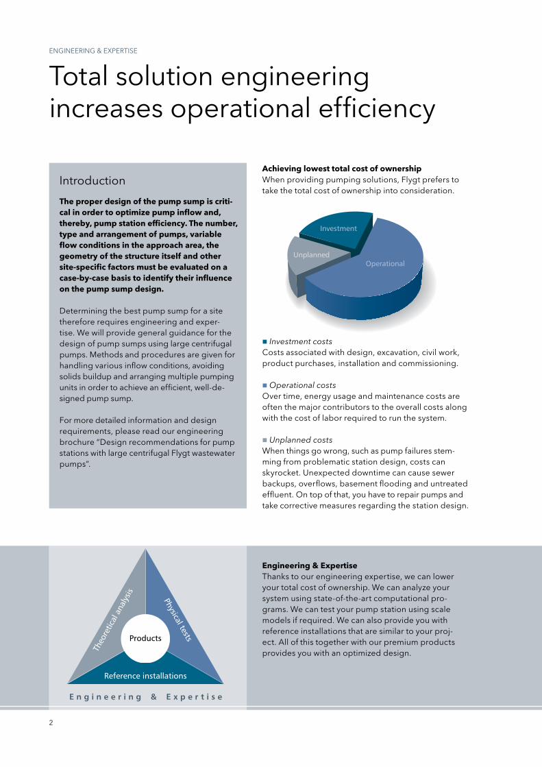
Achieving lowest total cost of ownershipWhen providing pumping solutions, Flygt prefers to take the total cost of ownership into consideration.
Engineering & Expertisethanks to our engineering expertise, we can lower your total cost of ownership. We can analyze your system using state-of-the-art computational pro-grams. We can test your pump station using scale models if required. We can also provide you with reference installations that are similar to your proj-ect. All of this together with our premium products provides you with an optimized design.
total solution engineeringincreases operational efficiency
Investment costsCosts associated with design, excavation, civil work, product purchases, installation and commissioning.
Operational costsOver time, energy usage and maintenance costs are often the major contributors to the overall costs along with the cost of labor required to run the system.
Unplanned costsWhen things go wrong, such as pump failures stem-ming from problematic station design, costs can sky rocket. Unexpected downtime can cause sewer backups, overflows, basement flooding and untreated effluent. On top of that, you have to repair pumps and take corrective measures regarding the station design.
10
5
2
20
50
50 100 200 500 1,000 2,000 3,000
100
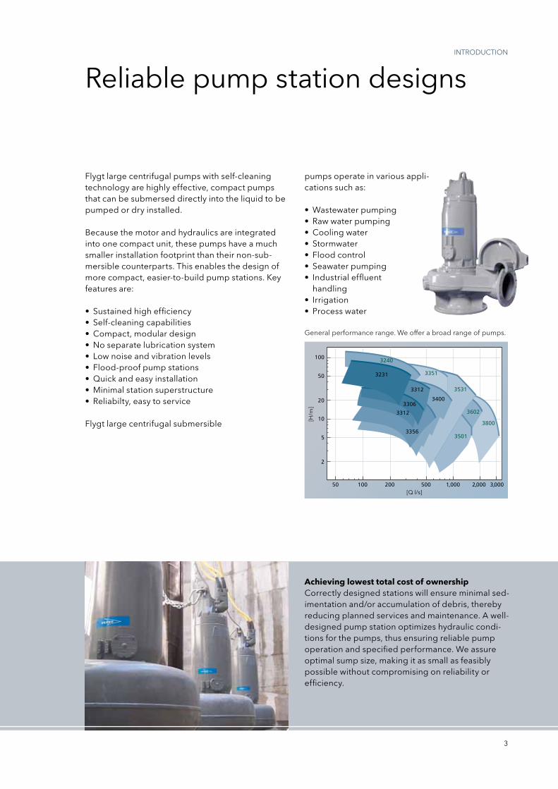
3231
3240
3351
3531
3602
3800
3501
3312
3400
3356
3312
3306
3
intrODUCtiOn
Achieving lowest total cost of ownershipCorrectly designed stations will ensure minimal sed-imentation and/or accumulation of debris, thereby reducing planned services and maintenance. A well-designed pump station optimizes hydraulic condi-tions for the pumps, thus ensuring reliable pump operation and specified performance. We assure optimal sump size, making it as small as feasibly possible without compromising on reliability or efficiency.
general performance range. We offer a broad range of pumps.
[Q l/s]
[H/m
]
Flygt large centrifugal pumps with self-cleaning technology are highly effective, compact pumps that can be submersed directly into the liquid to be pumped or dry installed.
Because the motor and hydraulics are integrated into one compact unit, these pumps have a much smaller installation footprint than their non-sub-mersible counterparts. this enables the design of more compact, easier-to-build pump stations. Key features are:
• Sustainedhighefficiency• Self-cleaningcapabilities• Compact,modulardesign• Noseparatelubricationsystem• Lownoiseandvibrationlevels• Flood-proofpumpstations• Quickandeasyinstallation• Minimalstationsuperstructure• Reliabilty,easytoservice
Flygt large centrifugal submersible
pumps operate in various appli-cations such as:
•Wastewaterpumping• Rawwaterpumping• Coolingwater• Stormwater• Floodcontrol• Seawaterpumping• Industrialeffluent
handling• Irrigation• Processwater
reliable pump station designs
4
Adverse hydraulic phenomena
DEsign COnDitiOns
to ensure the expected pump performance and long service intervals, it is important to design the pump sump to prevent adverse flow conditions.
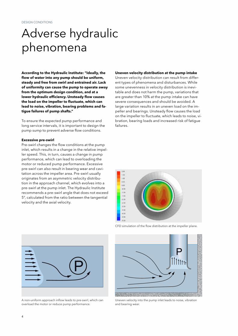
Excessive pre-swirlpre-swirl changes the flow conditions at the pump inlet, which results in a change in the relative impel-ler speed. this, in turn, causes a change in pump performance, which can lead to overloading the motor or reduced pump performance. Excessive pre-swirl can also result in bearing wear and cavi-tation across the impeller area. pre-swirl usually originates from an asymmetric velocity distribu-tion in the approach channel, which evolves into a pre-swirl at the pump inlet. the Hydraulic institute recommends a pre-swirl angle that does not exceed 5°, calculated from the ratio between the tangential velocity and the axial velocity.
According to the Hydraulic Institute: “Ideally, the flow of water into any pump should be uniform, steady and free from swirl and entrained air. Lack of uniformity can cause the pump to operate away from the optimum design condition, and at a lower hydraulic efficiency. Unsteady flow causes the load on the impeller to fluctuate, which can lead to noise, vibration, bearing problems and fa-tigue failures of pump shafts.”
Uneven velocity distribution at the pump intakeUneven velocity distribution can result from differ-ent types of phenomena and disturbances. While some unevenness in velocity distribution is inevi-table and does not harm the pump, variations that are greater than 10% at the pump intake can have severe consequences and should be avoided. A large variation results in an uneven load on the im-peller and bearings. Unsteady flow causes the load on the impeller to fluctuate, which leads to noise, vi-bration, bearing loads and increased risk of fatigue failures.
A non-uniform approach inflow leads to pre-swirl, which can overload the motor or reduce pump performance.
Uneven velocity into the pump inlet leads to noise, vibrationand bearing wear.
CFD simulation of the flow distribution at the impeller plane.
5
Entrained airit is widely known that even minor air entrainment, of some 3.4% of the volume, will lead to a clear reduction in pump performance and loss of effi-ciency; the severity depends upon the quantity of air entrained and the pump type. the expansion of ingested air bubbles within the impeller may result in mechanical imbalance, vibration and accelera-tion of mechanical wear. normal design practices recommend the exclusion of any air entrainment in the approach flow to the pump intake. in addition, entrained air leads to increased corrosion.
While air bubbles may be present in the liquid for a variety of reasons, their presence is usually due to cascading of the water as it enters the sump from a weir, culvert or incoming pipe located above the surface water level in the sump.
VorticesUnlike excessive pre-swirl, vortices appear locally with higher intensity and are a major hindrance to proper pump operation, resulting in cavitation, uneven load, noise and vibration. there are several different types of vortices.
the most commonly known type is the free surface vortex, which can have varying degrees of intensity – from weak surface vortices to fully developed vor-tices with a continuous air core that extends from the surface into the pump.
Lesswellknown,butjustascommonisthevortexthat originates under the surface from the sump bottom, walls or between two pumps, and extends to the pump inlet. this type of vortex can achieve high rotational speeds with high subpressures and cavitations.
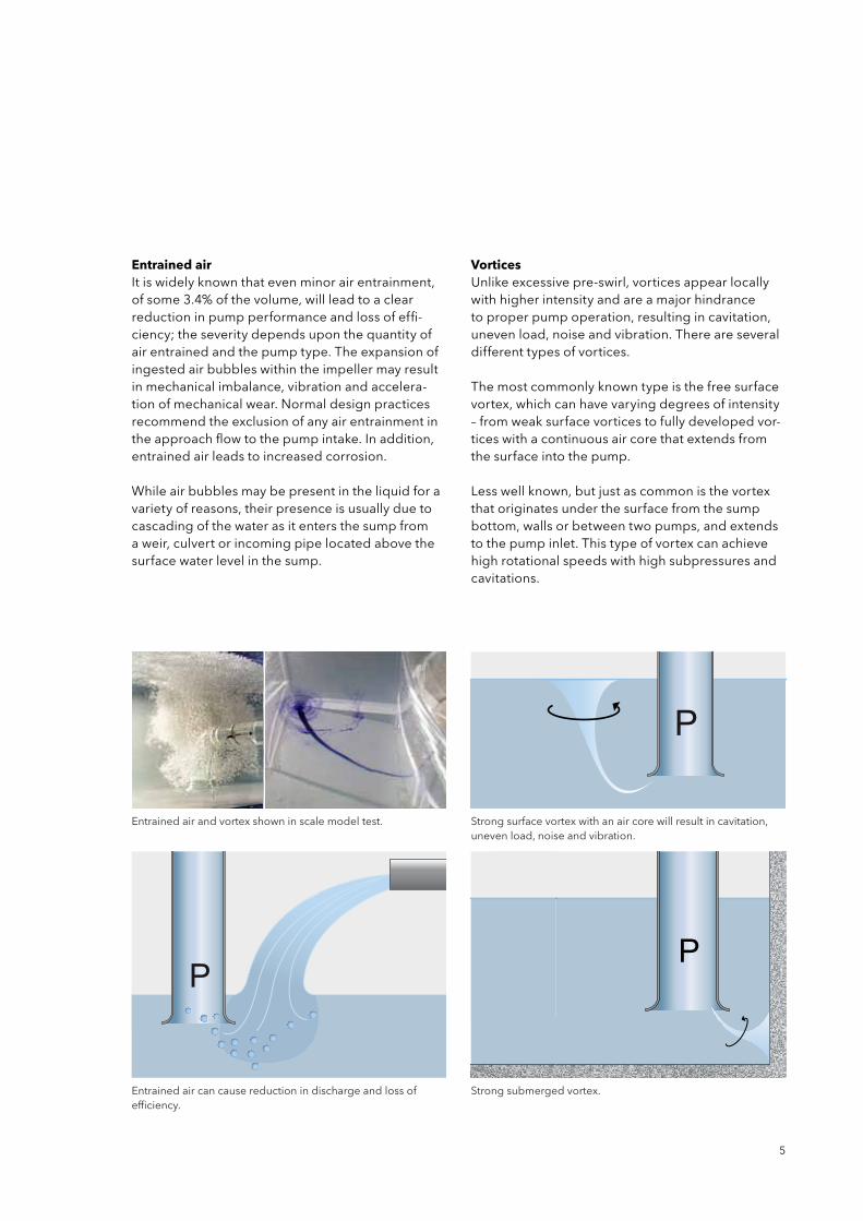
Entrained air can cause reduction in discharge and loss of efficiency.
strong submerged vortex.
strong surface vortex with an air core will result in cavitation,uneven load, noise and vibration.
Entrained air and vortex shown in scale model test.
6
sediment, floating debris and clogging problems
DEsign COnDitiOns
in addition to preventing the occurrence of adverse hydraulic phenomena, it is also important to design the station to minimize build up of sediment at the bottom of the sump and accumulation of floating debris.
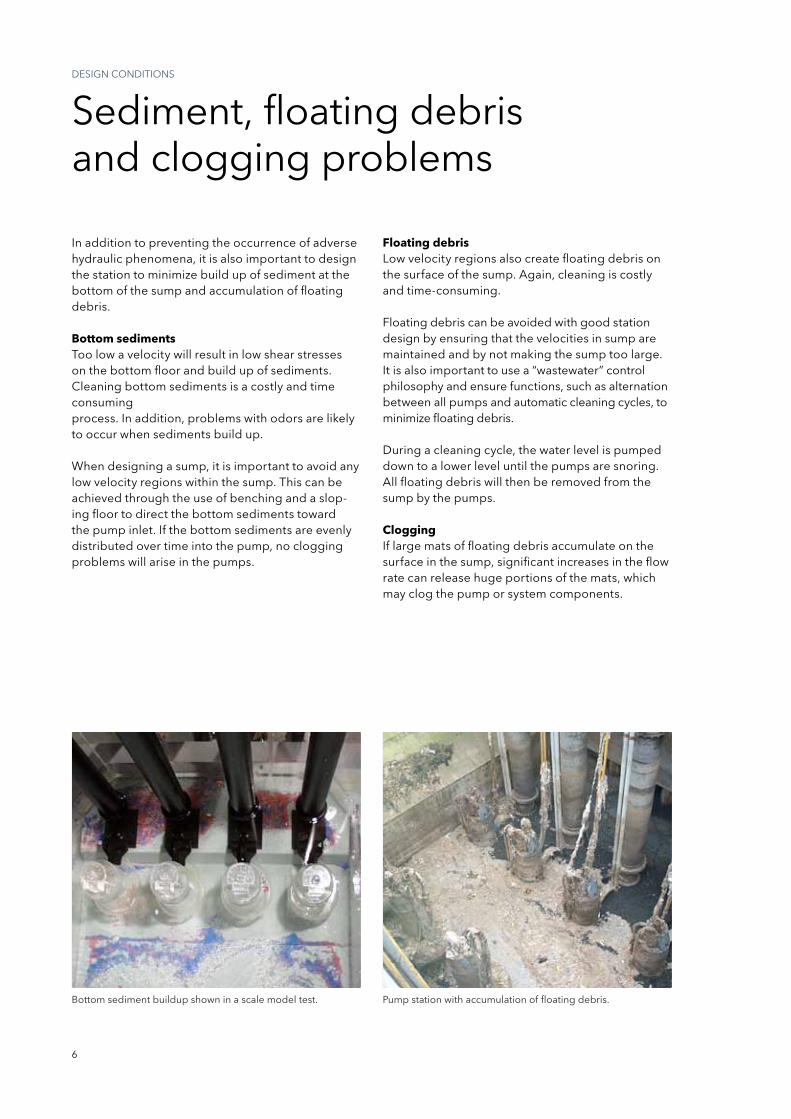
Bottom sedimentstoo low a velocity will result in low shear stresses on the bottom floor and build up of sediments. Cleaning bottom sediments is a costly and time consuming process. in addition, problems with odors are likely to occur when sediments build up.
When designing a sump, it is important to avoid any low velocity regions within the sump. this can be achieved through the use of benching and a slop-ing floor to direct the bottom sediments toward the pump inlet. if the bottom sediments are evenly distributed over time into the pump, no clogging problems will arise in the pumps.
Bottom sediment buildup shown in a scale model test. pump station with accumulation of floating debris.
Floating debrisLowvelocityregionsalsocreatefloatingdebrisonthe surface of the sump. Again, cleaning is costly and time-consuming. Floating debris can be avoided with good station design by ensuring that the velocities in sump are maintained and by not making the sump too large. it is also important to use a “wastewater” control philosophy and ensure functions, such as alternation between all pumps and automatic cleaning cycles, to minimize floating debris. During a cleaning cycle, the water level is pumped down to a lower level until the pumps are snoring. All floating debris will then be removed from the sump by the pumps.
Cloggingif large mats of floating debris accumulate on the surface in the sump, significant increases in the flow rate can release huge portions of the mats, which may clog the pump or system components.

7
Verified designpUMp stAtiOn DEsign
Centrifugal pump sump design verified through computational fluid dynamics (CFD).
Centrifugal pump sump design verified by a scale model test.
We have designed, developed and verified stan-dard Flygt branded pump stations. Extensive physi-cal tests, applications expertise and years of experi-ence have been utilized to optimize the design of Flygt pump stations.
Proven installationstoday there are thousands of pump stations in ac-cordance to the Flygt standard in operation all over the world. these have a proven track record of pre-venting sedimentation, clogging, floating debris and adverse hydraulics. Experience from existing Flygt pump stations is also a critical success factor when designing new pump stations.
Scale model testingWhen there is little or no prior experience, we use physical model testing to ensure the reliability in the design. A model is built to scale, typically at a 1:10 scale, on the basis of Froude number similarity, to preserve the laws of physics, and operated as a real installation. Analysis from the physical tests will show if the design is reliable and effective, and pro-vides a solution to ensure safe pumping operation.
Computational fluid dynamicsAnother method we use to verify design is computa-tional fluid dynamics (CFD), a mathematical mod-eling of the design where the flow pattern can be
observed.Flygt pioneered the use of CFD to verify sump design, and we have been using CFD for many years. Depending on the complexity of the installation, CFD can complement physical model testing or replace it entirely.
We have a number of standard Flygt sump designs, all of which have been tested extensively through physi-cal model testing, verified through CFD and proven through installations in use around the world. these sump designs have proven to minimize accumulation of sediments and debris and prevent adverse hydrau-lic conditions. When using standard Flygt designs, within the limits of our recommendations, there is no need for additional physical model testing or CFD.
8
reliable, cost- effective pumping
pUMp stAtiOn DEsign
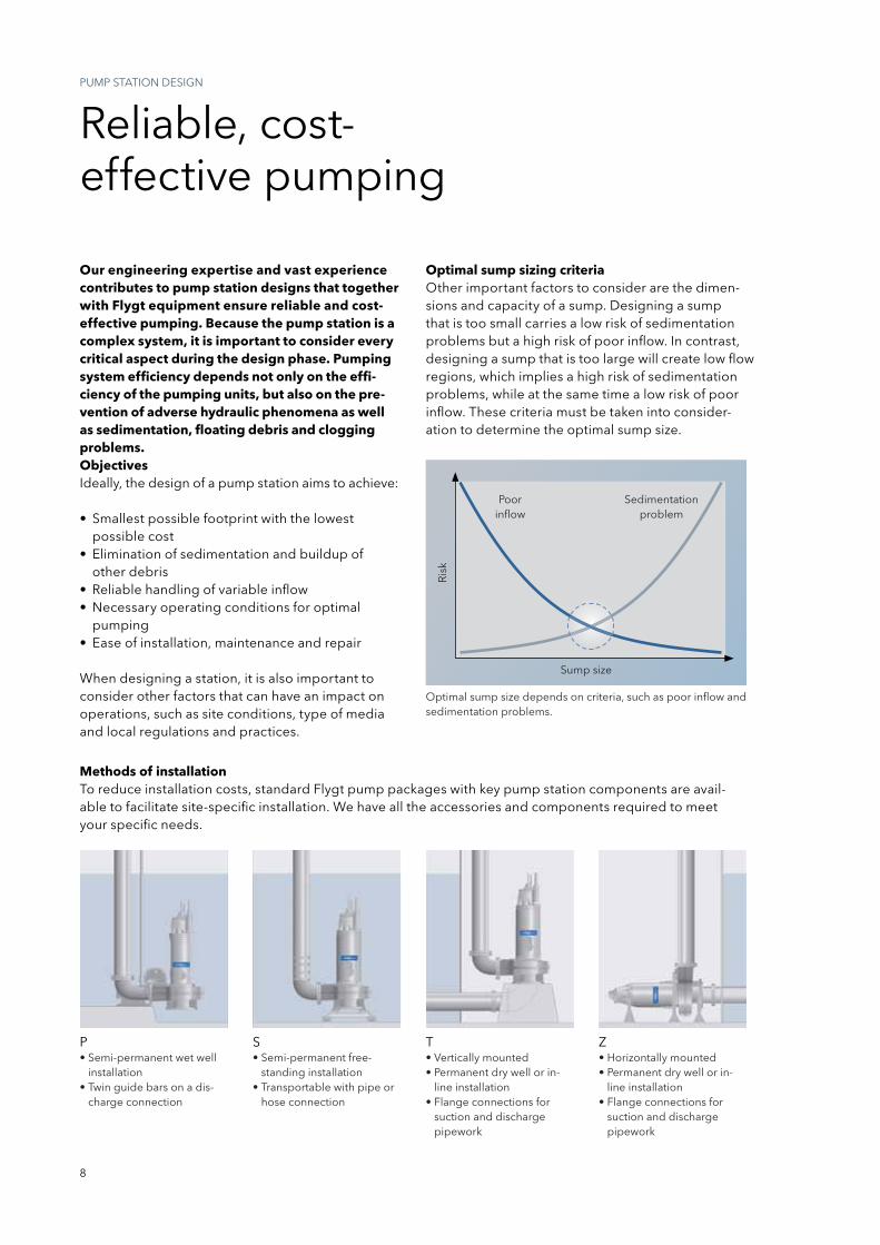
Our engineering expertise and vast experience contributes to pump station designs that together with Flygt equipment ensure reliable and cost-effective pumping. Because the pump station is a complex system, it is important to consider every critical aspect during the design phase. Pumping system efficiency depends not only on the effi-ciency of the pumping units, but also on the pre-vention of adverse hydraulic phenomena as well as sedimentation, floating debris and clogging problems.Objectivesideally, the design of a pump station aims to achieve:
• Smallestpossiblefootprintwiththelowest possible cost
• Eliminationofsedimentationandbuildupof other debris
• Reliablehandlingofvariableinflow• Necessaryoperatingconditionsforoptimal
pumping• Easeofinstallation,maintenanceandrepair
When designing a station, it is also important to consider other factors that can have an impact on operations, such as site conditions, type of media and local regulations and practices.
Optimal sump size depends on criteria, such as poor inflow and sedimentation problems.
Optimal sump sizing criteriaOther important factors to consider are the dimen-sions and capacity of a sump. Designing a sump that is too small carries a low risk of sedimentation problems but a high risk of poor inflow. in contrast, designing a sump that is too large will create low flow regions, which implies a high risk of sedimentation problems, while at the same time a low risk of poor inflow. these criteria must be taken into consider-ation to determine the optimal sump size.
p•Semi-permanentwetwell
installation•Twinguidebarsonadis-
charge connection
t•Verticallymounted•Permanentdrywellorin-
line installation•Flangeconnectionsfor
suction and discharge pipework
s•Semi-permanentfree-
standing installation•Transportablewithpipeor
hose connection
Z•Horizontallymounted•Permanentdrywellorin-
line installation•Flangeconnectionsfor
suction and discharge pipework
Methods of installationto reduce installation costs, standard Flygt pump packages with key pump station components are avail-able to facilitate site-specific installation. We have all the accessories and components required to meet your specific needs.
sump size
poor inflow
sedimentation problem
ris
k
9
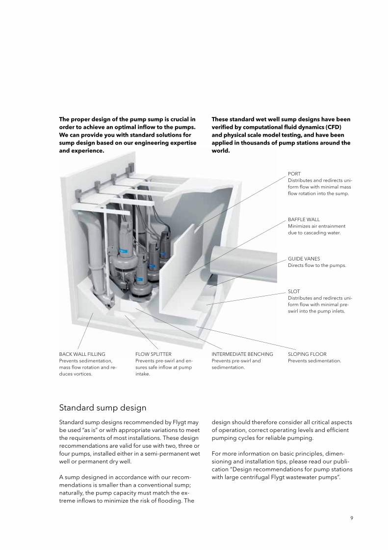
BACKWALLFILLINGprevents sedimentation, mass flow rotation and re-duces vortices.
standard sump design
standard sump designs recommended by Flygt may be used “as is” or with appropriate variations to meet the requirements of most installations. these design recommendations are valid for use with two, three or four pumps, installed either in a semi-permanent wet well or permanent dry well.
A sump designed in accordance with our recom-mendations is smaller than a conventional sump; naturally, the pump capacity must match the ex-treme inflows to minimize the risk of flooding. the
design should therefore consider all critical aspects of operation, correct operating levels and efficient pumping cycles for reliable pumping.
For more information on basic principles, dimen-sioning and installation tips, please read our publi-cation “Design recommendations for pump stations with large centrifugal Flygt wastewater pumps”.
pOrtDistributes and redirects uni-form flow with minimal mass flow rotation into the sump.
BAFFLEWALLMinimizes air entrainment due to cascading water.
gUiDE VAnEsDirects flow to the pumps.
SLOTDistributes and redirects uni-form flow with minimal pre-swirl into the pump inlets.
intErMEDiAtE BEnCHingprevents pre-swirl and sedimentation.
FLOWSPLITTERprevents pre-swirl and en-sures safe inflow at pump intake.
SLOPINGFLOORprevents sedimentation.
The proper design of the pump sump is crucial in order to achieve an optimal inflow to the pumps. We can provide you with standard solutions for sump design based on our engineering expertise and experience.
These standard wet well sump designs have been verified by computational fluid dynamics (CFD) and physical scale model testing, and have been applied in thousands of pump stations around the world.
10
standard wet well designs
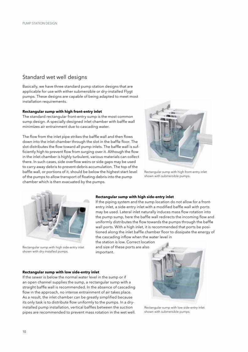
Basically, we have three standard pump station designs that are applicable for use with either submersible or dry-installed Flygt pumps. these designs are capable of being adapted to meet most installation requirements.
Rectangular sump with high front-entry inletthe standard rectangular front-entry sump is the most common sump design. A specially designed inlet chamber with baffle wall minimizes air entrainment due to cascading water.
the flow from the inlet pipe strikes the baffle wall and then flows down into the inlet chamber through the slot in the baffle floor. the slot distributes the flow toward all pump inlets. the baffle wall is suf-ficiently high to prevent flow from surging over it. Although the flow in the inlet chamber is highly turbulent, various materials can collect there. in such cases, side overflow weirs or side gaps may be used to carry away debris to prevent debris accumulation. the top of the baffle wall, or portions of it, should be below the highest start level of the pumps to allow transport of floating debris into the pump chamber which is then evacuated by the pumps.
Rectangular sump with high side-entry inletif the piping system and the sump location do not allow for a front-entry inlet, a side-entry inlet with a modified baffle wall with ports maybeused.Lateralinletnaturallyinducesmassflowrotationintothe pump sump, here the baffle wall redirects the incoming flow and uniformly distributes the flow towards the pumps through the baffle wall ports. With a high inlet, it is recommended that ports be posi-tioned along the inlet baffle chamber floor to dissipate the energy of the cascading inflow when the water level in the station is low. Correct location and size of these ports are also important.
Rectangular sump with low side-entry inletif the sewer is below the normal water level in the sump or if an open channel supplies the sump, a rectangular sump with a straight baffle wall is recommended. in the absence of cascading flow in the approach, no intense entrainment of air takes place. As a result, the inlet chamber can be greatly simplified because its only task is to distribute flow uniformly to the pumps. in a dry-installed pump installation, vertical baffles between the suction pipes are recommended to prevent mass rotation in the wet well.
pUMp stAtiOn DEsign
rectangular sump with high front-entry inlet shown with submersible pumps.
rectangular sump with high side-entry inlet shown with dry-installed pumps.
rectangular sump with low side-entry inlet shown with submersible pumps.
11
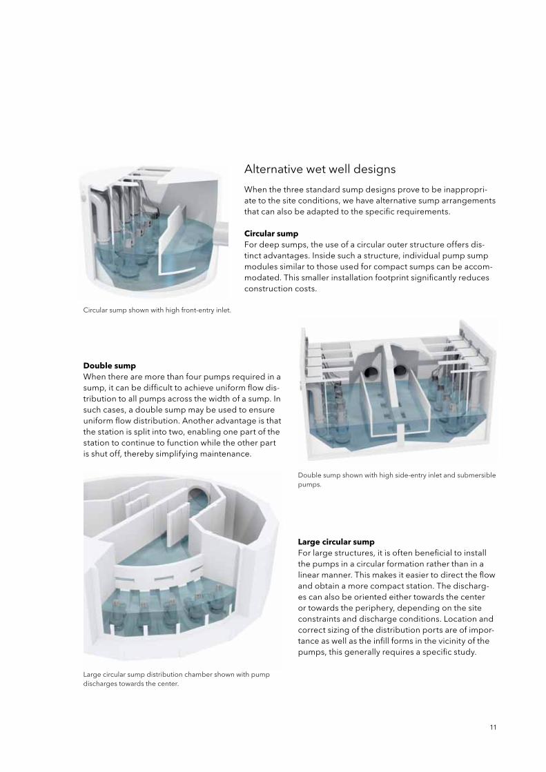
When the three standard sump designs prove to be inappropri-ate to the site conditions, we have alternative sump arrangements that can also be adapted to the specific requirements.
Circular sumpFor deep sumps, the use of a circular outer structure offers dis-tinct advantages. inside such a structure, individual pump sump modules similar to those used for compact sumps can be accom-modated. this smaller installation footprint significantly reduces construction costs.
Double sumpWhen there are more than four pumps required in a sump, it can be difficult to achieve uniform flow dis-tribution to all pumps across the width of a sump. in such cases, a double sump may be used to ensure uniform flow distribution. Another advantage is that the station is split into two, enabling one part of the station to continue to function while the other part is shut off, thereby simplifying maintenance.
Large circular sumpFor large structures, it is often beneficial to install the pumps in a circular formation rather than in a linear manner. this makes it easier to direct the flow and obtain a more compact station. the discharg-es can also be oriented either towards the center or towards the periphery, depending on the site constraintsanddischargeconditions.Locationandcorrect sizing of the distribution ports are of impor-tance as well as the infill forms in the vicinity of the pumps, this generally requires a specific study.
Alternative wet well designs
Circular sump shown with high front-entry inlet.
Largecircularsumpdistributionchambershownwithpumpdischarges towards the center.
Double sump shown with high side-entry inlet and submersible pumps.
12
proven worldwide
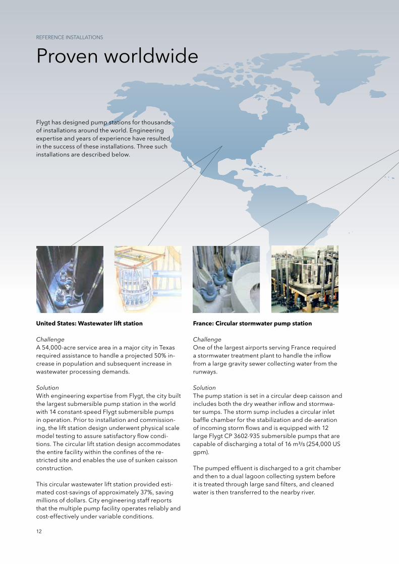
United States: Wastewater lift station
ChallengeA 54,000-acre service area in a major city in texas required assistance to handle a projected 50% in-crease in population and subsequent increase in wastewater processing demands.
SolutionWith engineering expertise from Flygt, the city built the largest submersible pump station in the world with 14 constant-speed Flygt submersible pumps in operation. prior to installation and commission-ing, the lift station design underwent physical scale model testing to assure satisfactory flow condi-tions. the circular lift station design accommodates the entire facility within the confines of the re-stricted site and enables the use of sunken caisson construction.
this circular wastewater lift station provided esti-mated cost-savings of approximately 37%, saving millions of dollars. City engineering staff reports that the multiple pump facility operates reliably and cost-effectively under variable conditions.
France: Circular stormwater pump station
ChallengeOne of the largest airports serving France required a stormwater treatment plant to handle the inflow from a large gravity sewer collecting water from the runways.
Solutionthe pump station is set in a circular deep caisson and includes both the dry weather inflow and stormwa-ter sumps. the storm sump includes a circular inlet baffle chamber for the stabilization and de-aeration of incoming storm flows and is equipped with 12 large Flygt Cp 3602-935 submersible pumps that are capable of discharging a total of 16 m³/s (254,000 Us gpm).
the pumped effluent is discharged to a grit chamber and then to a dual lagoon collecting system before it is treated through large sand filters, and cleaned water is then transferred to the nearby river.
Flygt has designed pump stations for thousands of installations around the world. Engineering expertise and years of experience have resulted in the success of these installations. three such installations are described below.
REFERENCEINSTALLATIONS
13
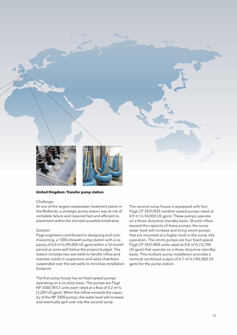
United Kingdom: Transfer pump station
Challenge:At one of the largest wastewater treatment plants in the Midlands, a strategic pump station was at risk of complete failure and required fast and efficient re-placement within the shortest possible timeframe.
Solution:Flygt engineers contributed to designing and com-missioning, a 1300-kilowatt pump station with a ca-pacity of 6.0 m3/s (95,000 Us gpm) within a 12-month period at costs well below the project budget. the station includes two wet wells to handle inflow and maintain solids in suspension and valve chambers suspended over the wet wells to minimize installation footprint.
the first sump house has six fixed-speed pumps operating on a six-duty basis. the pumps are Flygt NP3300.181LTunitseachratedataflowof0.2m3/s (3,200 Us gpm). When the inflow exceeds the capac-ity of the np 3300 pumps, the water level will increase and eventually spill over into the second sump.
the second sump house is equipped with four Flygt Cp 3531/835 variable-speed pumps rated at 0.9 m3/s (14,000 Us gpm). these pumps operate on a three-duty/one-standby basis. should inflow exceed the capacity of these pumps, the sump water level will increase and bring storm pumps that are mounted at a higher level in the sump into operation. the storm pumps are four fixed-speed Flygt Cp 3531/805 units rated at 0.8 m³/s (12,700 Us gpm) that operate on a three-duty/one-standby basis. this multiple pump installation provides a nominal combined output of 6.7 m3/s (106,000 Us gpm) for the pump station.
14
Engineering & ExpertisesErViCEs AnD sUppOrt
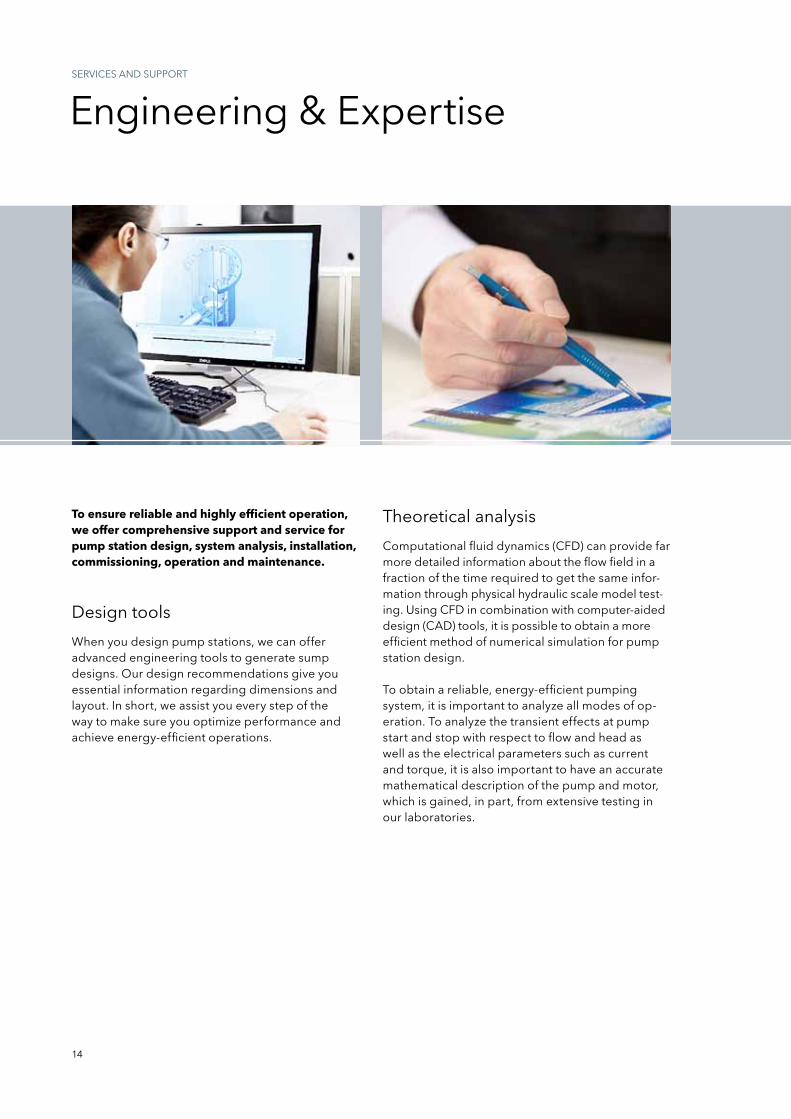
theoretical analysis
Design tools
Computational fluid dynamics (CFD) can provide far more detailed information about the flow field in a fraction of the time required to get the same infor-mation through physical hydraulic scale model test-ing. Using CFD in combination with computer-aided design (CAD) tools, it is possible to obtain a more efficient method of numerical simulation for pump station design.
to obtain a reliable, energy-efficient pumping system, it is important to analyze all modes of op-eration. to analyze the transient effects at pump start and stop with respect to flow and head as well as the electrical parameters such as current and torque, it is also important to have an accurate mathematical description of the pump and motor, which is gained, in part, from extensive testing in our laboratories.
When you design pump stations, we can offer advanced engineering tools to generate sump designs. Our design recommendations give you essential information regarding dimensions and layout. in short, we assist you every step of the way to make sure you optimize performance and achieve energy-efficient operations.
To ensure reliable and highly efficient operation, we offer comprehensive support and service for pump station design, system analysis, installation, commissioning, operation and maintenance.
Theo
retic
al a
naly
sis
Products
Reference installations
Physical tests
E n g i n e e r i n g & E x p e r t i s e
15
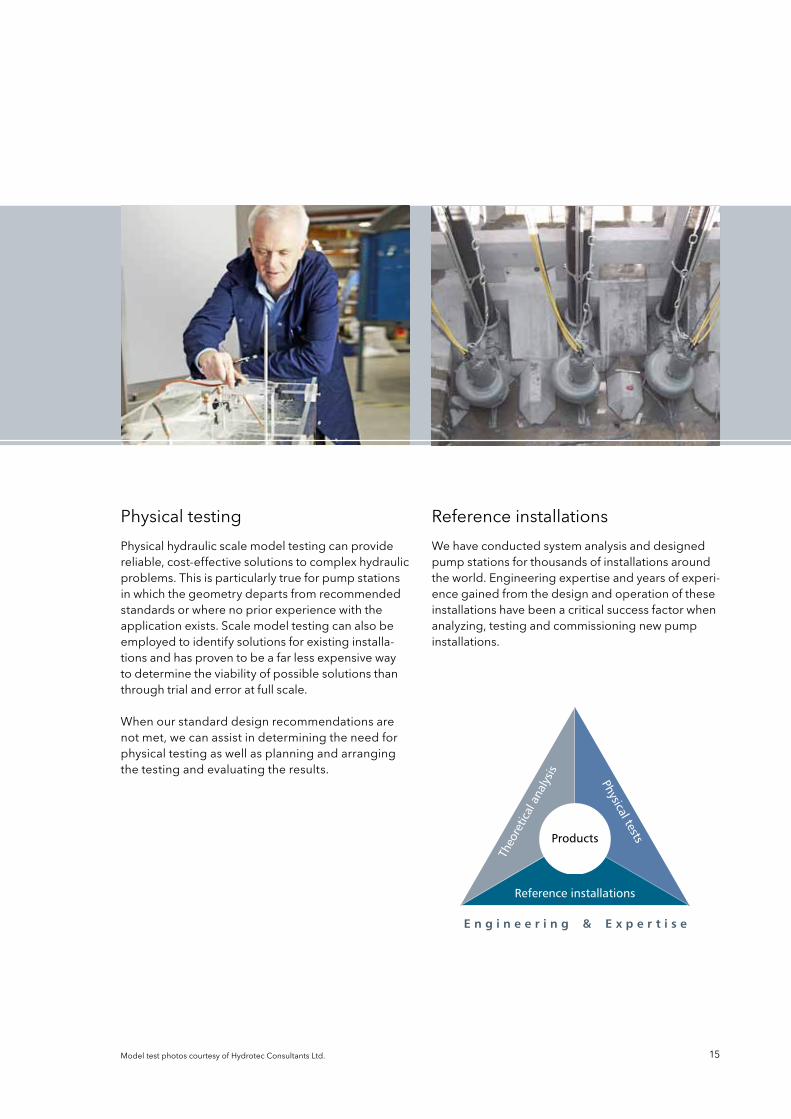
physical testing reference installations
physical hydraulic scale model testing can provide reliable, cost-effective solutions to complex hydraulic problems. this is particularly true for pump stations in which the geometry departs from recommended standards or where no prior experience with the application exists. scale model testing can also be employed to identify solutions for existing installa-tions and has proven to be a far less expensive way to determine the viability of possible solutions than through trial and error at full scale.
When our standard design recommendations are not met, we can assist in determining the need for physical testing as well as planning and arranging the testing and evaluating the results.
We have conducted system analysis and designed pump stations for thousands of installations around the world. Engineering expertise and years of experi-ence gained from the design and operation of these installations have been a critical success factor when analyzing, testing and commissioning new pump installations.
ModeltestphotoscourtesyofHydrotecConsultantsLtd.
Flygt is a brand of xylem. For the latest version of this document and more information about Flygt products visitwww.flygt.com
1201
. D
esig
ning
pum
p s
ump
s . 1
. M
aste
r . 1
. 20
1204
19
1) the tissue in plants that brings water upward from the roots 2) A leading global water technology company We’re 12,000 people unified in a common purpose: creating innovative solutions to meet our world’s water needs. Developing new technologies that will improve the way water is used, conserved, and re-used in the future is central to our work. We move, treat, analyze, and return water to the environment, and we help people use water efficiently, in their homes, buildings, factories and farms. in more than 150 countries, we have strong, long-standing relationships with customers who know us for our powerful combination of leading product brands and applications expertise, backed by a legacy of innovation. For more information on how xylem can help you, go to xyleminc.com.