Embed Size (px)
Citation preview
- 147 -
LARGE-SCALE FEM ANALYSIS OF THE DYNAMIC BEHAVIOR OF REIN-FORCED CONCRETE BUILDINGS Yasunori MIZUSHIMA, Research and Development Institute, Takenaka Corporation 1-5-1, Ohtsuka, Inzai, Chiba 270-1395 JAPAN Email: [email protected] Eizaburou TACHIBANA Professor Emeritus of Osaka University 2-1 Yamada-Oka, Suita, Osaka 565-0871, JAPAN Email: [email protected] Keywords: FEM, RC building, Erath Simulator, Soil-Structure Interaction SUMMARY In order to prevent urban disaster, it is very important to simulate the actual dynamic behavior of building structure suffering big earthquake. For this aim, usually, buildings are considered as simple model in which mass and springs are connected in series. However, these simple models are not enough to evaluate actual behavior buildings on earthquake. In this report, more accurate models are used for FEM analysis of RC buildings. The whole model is composed by upper framed structure, foundation, piles and surrounding soil. Concrete is modeled by solid element, rebar is modeled by beam element. Soil and underground structures transit forces each other through the contact surface. By using the Earth Simulator, numerical simulations are executed for this whole model. Large amount of information are obtained from these simulations. We can check at once the data of a necessary part, whichever it may be the micro dynamic behavior of a small steel bar or it may be the macro behavior of whole structure. This research will bring a new paradigm for structural designs when current supercomputers is popularized widely.
1. INTRODUCTION Until 1980’s, reinforced concrete structures were not applied for high rise buildings (taller than about 20 stories buildings). Most of them were designed as steel structures. But by virtue of the recent development of high strength cement, many high rise buildings have been constructing as reinforced concrete structure. However, those buildings have not experienced the big earthquake. Therefore, it is very important to predict the actual dynamic behaviors of those buildings by numerical simulations. Usually, numerical simulations are executed by simple models. Typical frame models for static simulation are composed by ‘linear elements'. One beam or one column is represented by one linear element. For dynamic simulations, 'mass and spring' models are used. One mass represents total mass of one floor. However, these simple models are not enough to explain the actual behavior of buildings on earthquake. In this report, more accurate models are used for FEM analysis
shown as Figure 1. Many civil engineers wanted to know the real behaviors of structures by using these accurate models. However, in this case the total number of variables will be larger than 10 millions. This number is out of scale for usual computers. 2. EARTH SIMULATOR The authors have made research about large-scale simulation1). In those reports, simulations were executed by using ES (The Earth Simulator) of JAMSTEC (Japan Agency for Marine-Earth Science and Technology) and those results showed us a first step towards paradigm shift of structural design for civil engineering. In this report, simulations are executed by ES2 (The Earth Simulator 2) whose computing power is about 3.2 times as high as that of previous ES (at peak). The machine power made more detailed and larger simulations possible. This time, RC (Reinforced Concrete) building model which is employed more precise (for cyclic loading) concrete material model intended for analysis model ( including surrounding soil).
International Symposium on Disaster Simulation & Structural Safty
in the Next Generation(DS’11) September 17-18, 2011, JAPAN
- 148 -
Plastic Hinges
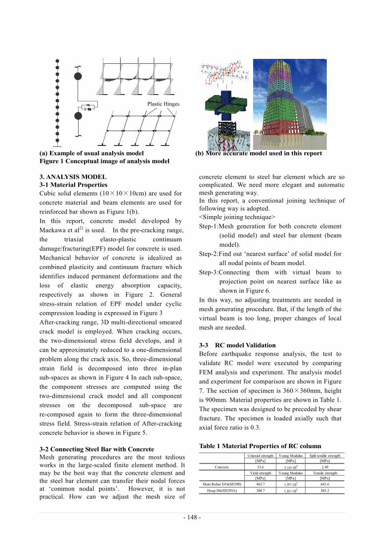
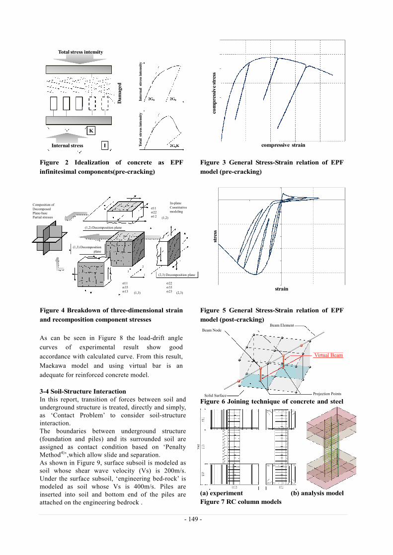
(a) Example of usual analysis model (b) More accurate model used in this report Figure 1 Conceptual image of analysis model 3. ANALYSIS MODEL 3-1 Mater ial Properties Cubic solid elements (10×10×10cm) are used for concrete material and beam elements are used for reinforced bar shown as Figure 1(b). In this report, concrete model developed by Maekawa et al2) is used. In the pre-cracking range, the triaxial elasto-plastic continuum damage/fracturing(EPF) model for concrete is used. Mechanical behavior of concrete is idealized as combined plasticity and continuum fracture which identifies induced permanent deformations and the loss of elastic energy absorption capacity, respectively as shown in Figure 2. General stress-strain relation of EPF model under cyclic compression loading is expressed in Figure 3 After-cracking range, 3D multi-directional smeared crack model is employed. When cracking occurs, the two-dimensional stress field develops, and it can be approximately reduced to a one-dimensional problem along the crack axis. So, three-dimensional strain field is decomposed into three in-plan sub-spaces as shown in Figure 4 In each sub-space, the component stresses are computed using the two-dimensional crack model and all component stresses on the decomposed sub-space are re-composed again to form the three-dimensional stress field. Stress-strain relation of After-cracking concrete behavior is shown in Figure 5. 3-2 Connecting Steel Bar with Concrete Mesh generating procedures are the most tedious works in the large-scaled finite element method. It may be the best way that the concrete element and the steel bar element can transfer their nodal forces at ‘common nodal points’. However, it is not practical. How can we adjust the mesh size of
concrete element to steel bar element which are so complicated. We need more elegant and automatic mesh generating way. In this report, a conventional joining technique of following way is adopted. <Simple joining technique> Step-1:Mesh generation for both concrete element
(solid model) and steel bar element (beam model).
Step-2:Find out ‘nearest surface’ of solid model for all nodal points of beam model.
Step-3:Connecting them with virtual beam to projection point on nearest surface like as shown in Figure 6.
In this way, no adjusting treatments are needed in mesh generating procedure. But, if the length of the virtual beam is too long, proper changes of local mesh are needed. 3-3 RC model Validation Before earthquake response analysis, the test to validate RC model were executed by comparing FEM analysis and experiment. The analysis model and experiment for comparison are shown in Figure 7. The section of specimen is 360×360mm, height is 900mm. Material properties are shown in Table 1. The specimen was designed to be preceded by shear fracture. The specimen is loaded axially such that axial force ratio is 0.3. Table 1 Mater ial Properties of RC column
Uniaxial strength Young Modulus Split tendile strength[MPa] [MPa] [MPa]
Concrete 33.6 3.14×10⁴ 2.49
Yield strength Young Modulus Tensile strength[MPa] [MPa] [MPa]
Main Rebar D16(SD390) 463.7 1.97×10⁵ 641.6
Hoop D6(SD295A) 304.7 1.81×10⁵ 503.2
- 149 -
Figure 2 Idealization of concrete as EPF infinitesimal components(pre-cracking) Figure 4 Breakdown of three-dimensional strain and recomposition component stresses
Figure 3 General Stress-Strain relation of EPF model (pre-cracking) Figure 5 General Stress-Strain relation of EPF model (post-cracking)
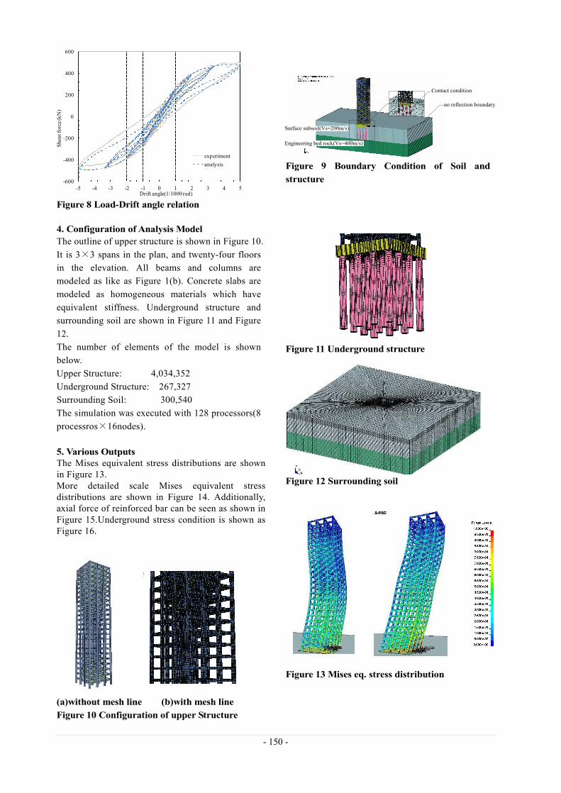
As can be seen in Figure 8 the load-drift angle curves of experimental result show good accordance with calculated curve. From this result, Maekawa model and using virtual bar is an adequate for reinforced concrete model. 3-4 Soil-Structure Interaction In this report, transition of forces between soil and underground structure is treated, directly and simply, as ‘Contact Problem’ to consider soil-structure interaction. The boundaries between underground structure (foundation and piles) and its surrounded soil are assigned as contact condition based on ‘Penalty Method4)’,which allow slide and separation. As shown in Figure 9, surface subsoil is modeled as soil whose shear wave velocity (Vs) is 200m/s. Under the surface subsoil, ‘engineering bed-rock’ is modeled as soil whose Vs is 400m/s. Piles are inserted into soil and bottom end of the piles are attached on the engineering bedrock .
Figure 6 Joining technique of concrete and steel
bar (a) exper iment (b) analysis model Figure 7 RC column models
1
2
3
(1,2)
In-planeConstitutivemodeling
(2,3) Decomposition plane
(1,3) Decomposition plane
(1,2) Decomposition plane
(2,3)(1,3)
s11s22s12
s11s33s13
s22s33s23
Composition of DecomposedPlane-basePartial stresses
Inte
rnal
str
ess
inte
nsit
yTo
tal
stre
ss in
tens
ity
2G0 2G0
2G0K
Total stress intensity
Internal stress
K
I
Dam
aged
stre
ss
strain
Beam NodeBeam Element
Solid Surface Projection Points
Virtual Beam
com
pres
sive
stre
ss
compressive strain
- 150 -
Figure 8 Load-Drift angle relation
Figure 9 Boundary Condition of Soil and structure
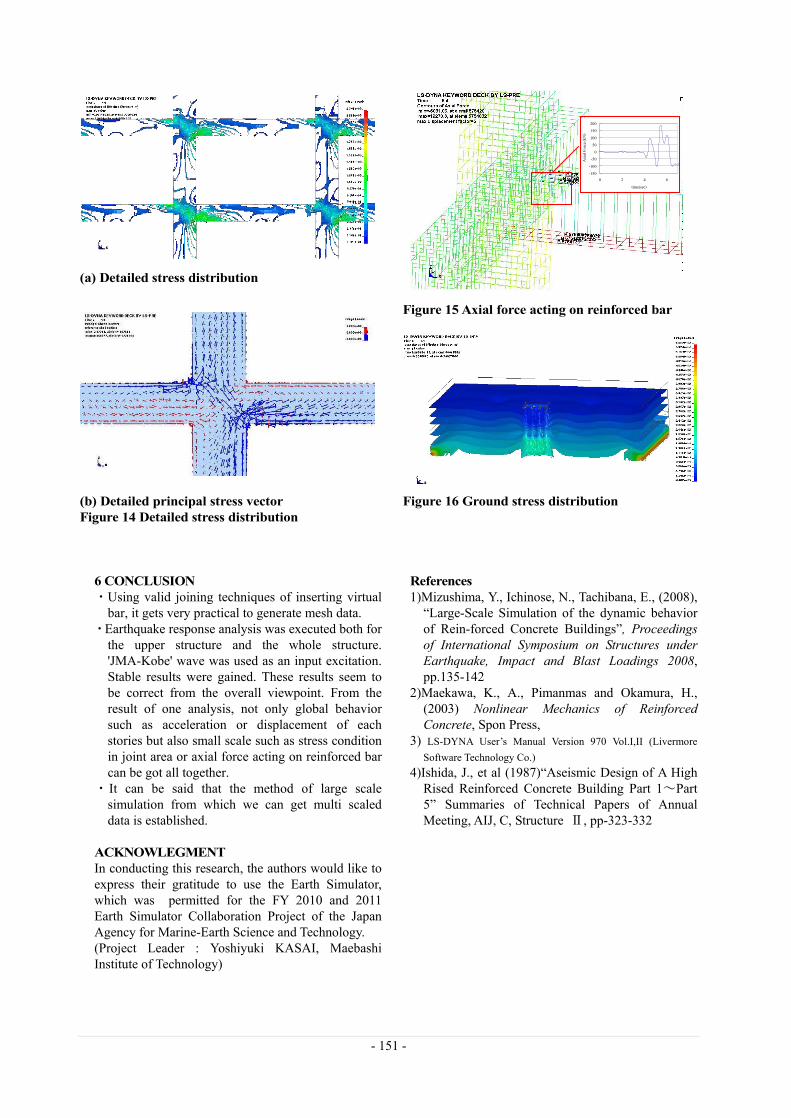
4. Configuration of Analysis Model The outline of upper structure is shown in Figure 10. It is 3×3 spans in the plan, and twenty-four floors in the elevation. All beams and columns are modeled as like as Figure 1(b). Concrete slabs are modeled as homogeneous materials which have equivalent stiffness. Underground structure and surrounding soil are shown in Figure 11 and Figure 12. The number of elements of the model is shown below. Upper Structure: 4,034,352 Underground Structure: 267,327 Surrounding Soil: 300,540 The simulation was executed with 128 processors(8 processros×16nodes). 5. Various Outputs The Mises equivalent stress distributions are shown in Figure 13. More detailed scale Mises equivalent stress distributions are shown in Figure 14. Additionally, axial force of reinforced bar can be seen as shown in Figure 15.Underground stress condition is shown as Figure 16. (a)without mesh line (b)with mesh line Figure 10 Configuration of upper Structure
Figure 11 Underground structure Figure 12 Surrounding soil Figure 13 Mises eq. stress distr ibution
-600
-400
-200
0
200
400
600
-5 -4 -3 -2 -1 0 1 2 3 4 5
Shea
r for
ce (k
N)
Drift angle(1/1000 rad)
experimentanalysis
Surface subsoil(Vs=200m/s)
Engineering bed rock(Vs=400m/s)
no reflection boundary
Contact condition
- 151 -
(a) Detailed stress distr ibution (b) Detailed pr incipal stress vector Figure 14 Detailed stress distr ibution
Figure 15 Axial force acting on reinforced bar Figure 16 Ground stress distr ibution
6 CONCLUSION ・Using valid joining techniques of inserting virtual
bar, it gets very practical to generate mesh data. ・Earthquake response analysis was executed both for
the upper structure and the whole structure. 'JMA-Kobe' wave was used as an input excitation. Stable results were gained. These results seem to be correct from the overall viewpoint. From the result of one analysis, not only global behavior such as acceleration or displacement of each stories but also small scale such as stress condition in joint area or axial force acting on reinforced bar can be got all together.
・It can be said that the method of large scale simulation from which we can get multi scaled data is established.
ACKNOWLEGMENT In conducting this research, the authors would like to express their gratitude to use the Earth Simulator, which was permitted for the FY 2010 and 2011 Earth Simulator Collaboration Project of the Japan Agency for Marine-Earth Science and Technology. (Project Leader : Yoshiyuki KASAI, Maebashi Institute of Technology)
References 1)Mizushima, Y., Ichinose, N., Tachibana, E., (2008),
“Large-Scale Simulation of the dynamic behavior of Rein-forced Concrete Buildings”, Proceedings of International Symposium on Structures under Earthquake, Impact and Blast Loadings 2008, pp.135-142
2)Maekawa, K., A., Pimanmas and Okamura, H., (2003) Nonlinear Mechanics of Reinforced Concrete, Spon Press,
3) LS-DYNA User’s Manual Version 970 Vol.I,II (Livermore Software Technology Co.)
4)Ishida, J., et al (1987)“Aseismic Design of A High Rised Reinforced Concrete Building Part 1~Part 5” Summaries of Technical Papers of Annual Meeting, AIJ, C, Structure Ⅱ, pp-323-332
-150
-100
-50
0
50
100
150
200
0 2 4 6
time(sec)
Axi
al F
orce
(kN
)