Embed Size (px)
Citation preview
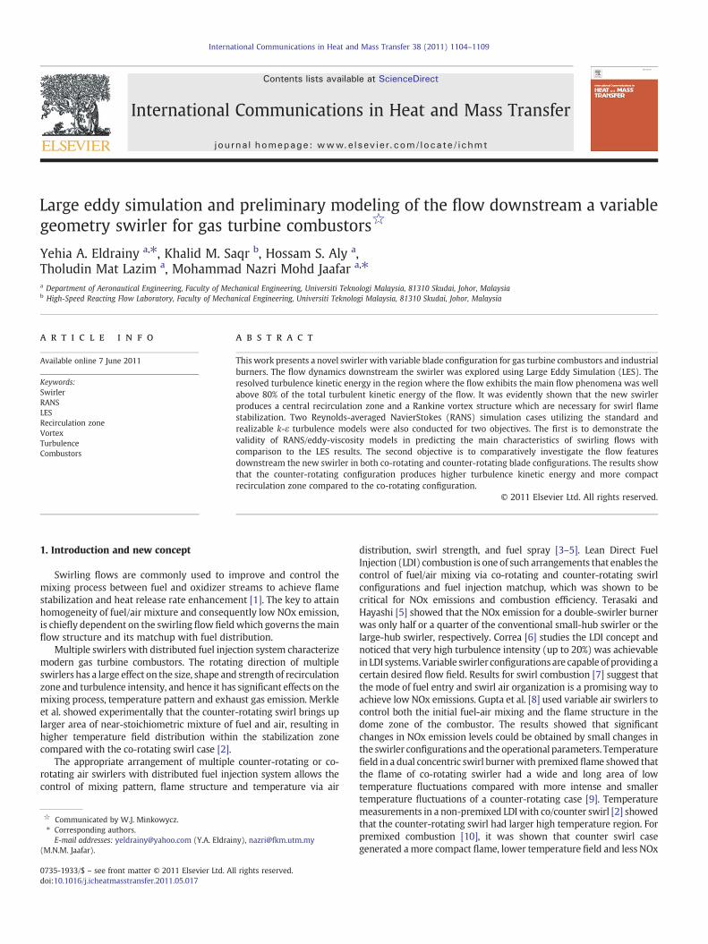
International Communications in Heat and Mass Transfer 38 (2011) 1104–1109
Contents lists available at ScienceDirect
International Communications in Heat and Mass Transfer
j ourna l homepage: www.e lsev ie r.com/ locate / ichmt
Large eddy simulation and preliminary modeling of the flow downstream a variablegeometry swirler for gas turbine combustors☆
Yehia A. Eldrainy a,⁎, Khalid M. Saqr b, Hossam S. Aly a,Tholudin Mat Lazim a, Mohammad Nazri Mohd Jaafar a,⁎a Department of Aeronautical Engineering, Faculty of Mechanical Engineering, Universiti Teknologi Malaysia, 81310 Skudai, Johor, Malaysiab High-Speed Reacting Flow Laboratory, Faculty of Mechanical Engineering, Universiti Teknologi Malaysia, 81310 Skudai, Johor, Malaysia
☆ Communicated by W.J. Minkowycz.⁎ Corresponding authors.
E-mail addresses: [email protected] (Y.A. Eldrai(M.N.M. Jaafar).
0735-1933/$ – see front matter © 2011 Elsevier Ltd. Aldoi:10.1016/j.icheatmasstransfer.2011.05.017
a b s t r a c t
a r t i c l e i n f oAvailable online 7 June 2011
Keywords:SwirlerRANSLESRecirculation zoneVortexTurbulenceCombustors
This work presents a novel swirler with variable blade configuration for gas turbine combustors and industrialburners. The flow dynamics downstream the swirler was explored using Large Eddy Simulation (LES). Theresolved turbulence kinetic energy in the region where the flow exhibits the main flow phenomena was wellabove 80% of the total turbulent kinetic energy of the flow. It was evidently shown that the new swirlerproduces a central recirculation zone and a Rankine vortex structure which are necessary for swirl flamestabilization. Two Reynolds-averaged NavierStokes (RANS) simulation cases utilizing the standard andrealizable k-ε turbulence models were also conducted for two objectives. The first is to demonstrate thevalidity of RANS/eddy-viscosity models in predicting the main characteristics of swirling flows withcomparison to the LES results. The second objective is to comparatively investigate the flow featuresdownstream the new swirler in both co-rotating and counter-rotating blade configurations. The results showthat the counter-rotating configuration produces higher turbulence kinetic energy and more compactrecirculation zone compared to the co-rotating configuration.
ny), [email protected]
l rights reserved.
© 2011 Elsevier Ltd. All rights reserved.
1. Introduction and new concept
Swirling flows are commonly used to improve and control themixing process between fuel and oxidizer streams to achieve flamestabilization and heat release rate enhancement [1]. The key to attainhomogeneity of fuel/air mixture and consequently low NOx emission,is chiefly dependent on the swirling flow fieldwhich governs themainflow structure and its matchup with fuel distribution.
Multiple swirlers with distributed fuel injection system characterizemodern gas turbine combustors. The rotating direction of multipleswirlers has a large effect on the size, shape and strength of recirculationzone and turbulence intensity, and hence it has significant effects on themixing process, temperature pattern and exhaust gas emission. Merkleet al. showed experimentally that the counter-rotating swirl brings uplarger area of near-stoichiometric mixture of fuel and air, resulting inhigher temperature field distribution within the stabilization zonecompared with the co-rotating swirl case [2].
The appropriate arrangement of multiple counter-rotating or co-rotating air swirlers with distributed fuel injection system allows thecontrol of mixing pattern, flame structure and temperature via air
distribution, swirl strength, and fuel spray [3–5]. Lean Direct FuelInjection (LDI) combustion is one of such arrangements that enables thecontrol of fuel/air mixing via co-rotating and counter-rotating swirlconfigurations and fuel injection matchup, which was shown to becritical for NOx emissions and combustion efficiency. Terasaki andHayashi [5] showed that the NOx emission for a double-swirler burnerwas only half or a quarter of the conventional small-hub swirler or thelarge-hub swirler, respectively. Correa [6] studies the LDI concept andnoticed that very high turbulence intensity (up to 20%) was achievablein LDI systems. Variable swirler configurationsare capable of providing acertain desired flow field. Results for swirl combustion [7] suggest thatthe mode of fuel entry and swirl air organization is a promising way toachieve low NOx emissions. Gupta et al. [8] used variable air swirlers tocontrol both the initial fuel-air mixing and the flame structure in thedome zone of the combustor. The results showed that significantchanges in NOx emission levels could be obtained by small changes inthe swirler configurations and the operational parameters. Temperaturefield in a dual concentric swirl burnerwith premixed flame showed thatthe flame of co-rotating swirler had a wide and long area of lowtemperature fluctuations compared with more intense and smallertemperature fluctuations of a counter-rotating case [9]. Temperaturemeasurements in a non-premixed LDIwith co/counter swirl [2] showedthat the counter-rotating swirl had larger high temperature region. Forpremixed combustion [10], it was shown that counter swirl casegenerated amore compact flame, lower temperature field and less NOx
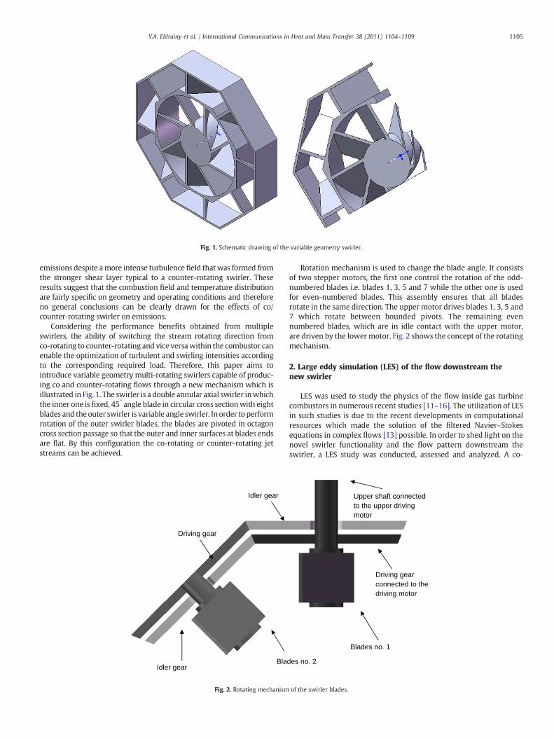
Fig. 1. Schematic drawing of the variable geometry swirler.
1105Y.A. Eldrainy et al. / International Communications in Heat and Mass Transfer 38 (2011) 1104–1109
emissions despite amore intense turbulence field thatwas formed fromthe stronger shear layer typical to a counter-rotating swirler. Theseresults suggest that the combustion field and temperature distributionare fairly specific on geometry and operating conditions and thereforeno general conclusions can be clearly drawn for the effects of co/counter-rotating swirler on emissions.
Considering the performance benefits obtained from multipleswirlers, the ability of switching the stream rotating direction fromco-rotating to counter-rotating and vice versawithin the combustor canenable the optimization of turbulent and swirling intensities accordingto the corresponding required load. Therefore, this paper aims tointroduce variable geometry multi-rotating swirlers capable of produc-ing co and counter-rotating flows through a new mechanism which isillustrated in Fig. 1. The swirler is a double annular axial swirler inwhichthe inner one is fixed, 45° angle blade in circular cross sectionwith eightblades and the outer swirler is variable angle swirler. In order to performrotation of the outer swirler blades, the blades are pivoted in octagoncross section passage so that the outer and inner surfaces at blades endsare flat. By this configuration the co-rotating or counter-rotating jetstreams can be achieved.
Bla
Driving gear
Idler gear
Idler gear
Fig. 2. Rotating mechanism
Rotation mechanism is used to change the blade angle. It consistsof two stepper motors, the first one control the rotation of the odd-numbered blades i.e. blades 1, 3, 5 and 7 while the other one is usedfor even-numbered blades. This assembly ensures that all bladesrotate in the same direction. The upper motor drives blades 1, 3, 5 and7 which rotate between bounded pivots. The remaining evennumbered blades, which are in idle contact with the upper motor,are driven by the lowermotor. Fig. 2 shows the concept of the rotatingmechanism.
2. Large eddy simulation (LES) of the flow downstream thenew swirler
LES was used to study the physics of the flow inside gas turbinecombustors in numerous recent studies [11–16]. The utilization of LESin such studies is due to the recent developments in computationalresources which made the solution of the filtered Navier–Stokesequations in complex flows [13] possible. In order to shed light on thenovel swirler functionality and the flow pattern downstream theswirler, a LES study was conducted, assessed and analyzed. A co-
Driving gear connected to the driving motor
des no. 2
Upper shaft connected to the upper driving motor
Blades no. 1
of the swirler blades.
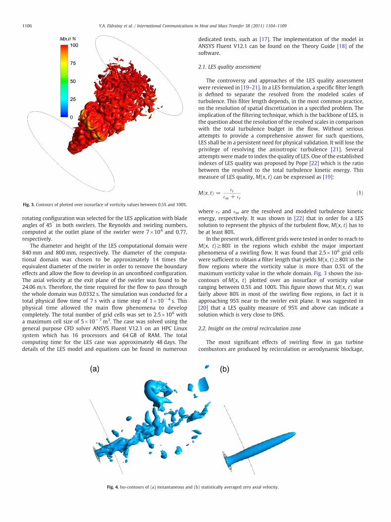
Fig. 3. Contours of plotted over isosurface of vorticity values between 0.5% and 100%.
1106 Y.A. Eldrainy et al. / International Communications in Heat and Mass Transfer 38 (2011) 1104–1109
rotating configuration was selected for the LES application with bladeangles of 45° in both swirlers. The Reynolds and swirling numbers,computed at the outlet plane of the swirler were 7×10⁴ and 0.77,respectively.
The diameter and height of the LES computational domain were840 mm and 800 mm, respectively. The diameter of the computa-tional domain was chosen to be approximately 14 times theequivalent diameter of the swirler in order to remove the boundaryeffects and allow the flow to develop in an unconfined configuration.The axial velocity at the exit plane of the swirler was found to be24.06 m/s. Therefore, the time required for the flow to pass throughthe whole domain was 0.0332 s. The simulation was conducted for atotal physical flow time of 7 s with a time step of 1×10⁻⁴ s. Thisphysical time allowed the main flow phenomena to developcompletely. The total number of grid cells was set to 2.5×10⁶ witha maximum cell size of 5×10⁻⁷ m3. The case was solved using thegeneral purpose CFD solver ANSYS Fluent V12.1 on an HPC Linuxsystem which has 16 processors and 64 GB of RAM. The totalcomputing time for the LES case was approximately 48 days. Thedetails of the LES model and equations can be found in numerous
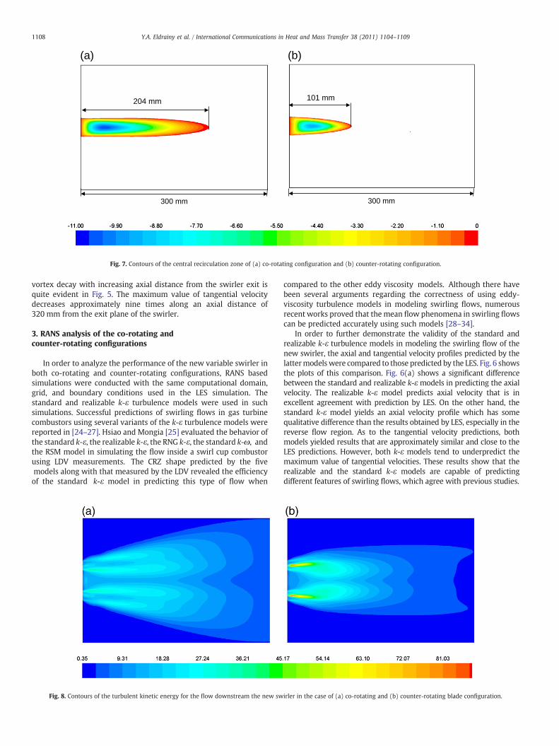
Fig. 4. Iso-contours of (a) instantaneous and (b
dedicated texts, such as [17]. The implementation of the model inANSYS Fluent V12.1 can be found on the Theory Guide [18] of thesoftware.
2.1. LES quality assessment
The controversy and approaches of the LES quality assessmentwere reviewed in [19–21]. In a LES formulation, a specific filter lengthis defined to separate the resolved from the modeled scales ofturbulence. This filter length depends, in the most common practice,on the resolution of spatial discretization in a specified problem. Theimplication of the filtering technique, which is the backbone of LES, isthe question about the resolution of the resolved scales in comparisonwith the total turbulence budget in the flow. Without seriousattempts to provide a comprehensive answer for such questions,LES shall be in a persistent need for physical validation. It will lose theprivilege of resolving the anisotropic turbulence [21]. Severalattempts weremade to index the quality of LES. One of the establishedindexes of LES quality was proposed by Pope [22] which is the ratiobetween the resolved to the total turbulence kinetic energy. Thismeasure of LES quality, M(x, t) can be expressed as [19]:
M x; tð Þ = �r�m + �r
ð1Þ
where �r and �m are the resolved and modeled turbulence kineticenergy, respectively. It was shown in [22] that in order for a LESsolution to represent the physics of the turbulent flow, M(x, t) has tobe at least 80%.
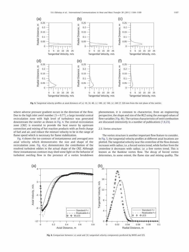
In the present work, different grids were tested in order to reach toM(x, t)≥80% in the regions which exhibit the major importantphenomena of a swirling flow. It was found that 2.5×10⁶ grid cellswere sufficient to obtain a filter length that yields M(x, t)≥80% in theflow regions where the vorticity value is more than 0.5% of themaximum vorticity value in the whole domain. Fig. 3 shows the iso-contours ofM(x, t) plotted over an isosurface of vorticity valueranging between 0.5% and 100%. This figure shows that M(x, t) wasfairly above 80% in most of the swirling flow regions, in fact it isapproaching 95% near to the swirler exit plane. It was suggested in[20] that a LES quality measure of 95% and above can indicate asolution which is very close to DNS.
2.2. Insight on the central recirculation zone
The most significant effects of swirling flow in gas turbinecombustors are produced by recirculation or aerodynamic blockage,
) statistically averaged zero axial velocity.
0.25
0.2
0.15
0.1
0.05
0
Rad
ial D
ista
nce,
m
0.25
0.2
0.15
0.1
0.05
0
Rad
ial D
ista
nce,
m
0.25
0.2
0.15
0.1
0.05
0
Rad
ial D
ista
nce,
m
0.25
0.2
0.15
0.1
0.05
0
Rad
ial D
ista
nce,
m
0.25
0.2
0.15
0.1
0.05
0
Rad
ial D
ista
nce,
m
0.25
0.2
0.15
0.1
0.05
0
Rad
ial D
ista
nce,
m
0 5 10 15 20 25
Tangential Velocity, m/s0 5 10 15 20 25
Tangential Velocity, m/s0 5 10 15 20 25
Tangential Velocity, m/s
0 5 10 15 20 25
Tangential Velocity, m/s0 5 10 15 20 25
Tangential Velocity, m/s0 5 10 15 20 25
Tangential Velocity, m/s
(a) (b) (c)
(d) (e) (f)
Fig. 5. Tangential velocity profiles at axial distances of (a) 10, (b) 40, (c) 100, (d) 160, (e) 240 (f) 320 mm from the exit plane of the swirler.
1107Y.A. Eldrainy et al. / International Communications in Heat and Mass Transfer 38 (2011) 1104–1109
where adverse pressure gradient occurs in the direction of the flow.Due to the high inlet swirl number (S=0.77), a large toroidal centralrecirculation zone with high level of turbulence was generateddownstream the swirler as shown in Fig. 4. The central recirculationzone (CRZ) is essential to provide the heat source by upstreamconvection and mixing of hot reaction products with an fresh chargeof fuel and air, and reduce the mixture velocity to be in the range offlame speed which is necessary for flame stabilization.
Fig. 4 shows the iso-contours of instantaneous and averaged zeroaxial velocity which demonstrates the size and shape of therecirculation zone. Fig. 4(a) demonstrates the contribution of theresolved turbulent eddies in the actual shape of the CRZ. Althoughthese instantaneous contours may shed some light on the behavior ofturbulent swirling flow in the presence of a vortex breakdown
(a) (4
0
-4
-8
-12
0 0.2 0.4 0.6 0.8
Axi
al V
eloc
ity, m
/s
Axial Distance, m
k-εk-ε
StandardRealizableLES
Fig. 6. Comparison between (a) axial and (b) tangentia
phenomenon, it is common to characterize, from an engineeringperspective, the shape and size of the RCZ using the averaged values offlowvariables (Fig. 4b). The various characteristics of swirl combustionare discussed extensively in a number of publications [7,8,23].
2.3. Vortex structure
The vortex structure is another important flow feature to consider.In Fig. 5, the tangential velocity profiles at different axial locations areplotted. The tangential velocity near the centerline of the flow domainincreases with radius; i.e. a forced vortex trend, while further from thecenterline it decreases with radius; i.e. a free vortex trend. This isknown as the Rankine vortex flow. The decay of forced vortexdetermines, to some extent, the flame size and mixing quality. The
b)20
16
12
8
4
0
0 0.02 0.04 0.06 0.08 0.1
Tan
gent
ial V
eloc
ity, m
/s
Radial Distance, m
k-εk-ε
StandardRealizableLES
l velocity components predicted by RANS and LES.
300 mm
204 mm
(a)
300 mm
101 mm
(b)
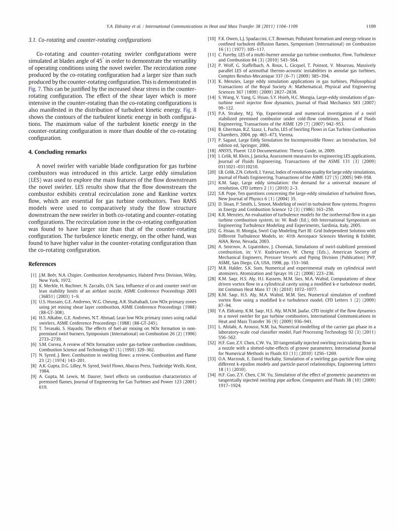
Fig. 7. Contours of the central recirculation zone of (a) co-rotating configuration and (b) counter-rotating configuration.
1108 Y.A. Eldrainy et al. / International Communications in Heat and Mass Transfer 38 (2011) 1104–1109
vortex decay with increasing axial distance from the swirler exit isquite evident in Fig. 5. The maximum value of tangential velocitydecreases approximately nine times along an axial distance of320 mm from the exit plane of the swirler.
3. RANS analysis of the co-rotating andcounter-rotating configurations
In order to analyze the performance of the new variable swirler inboth co-rotating and counter-rotating configurations, RANS basedsimulations were conducted with the same computational domain,grid, and boundary conditions used in the LES simulation. Thestandard and realizable k-ε turbulence models were used in suchsimulations. Successful predictions of swirling flows in gas turbinecombustors using several variants of the k-ε turbulence models werereported in [24–27]. Hsiao and Mongia [25] evaluated the behavior ofthe standard k-ε, the realizable k-ε, the RNG k-ε, the standard k-ω, andthe RSM model in simulating the flow inside a swirl cup combustorusing LDV measurements. The CRZ shape predicted by the fivemodels along with that measured by the LDV revealed the efficiencyof the standard k-ε model in predicting this type of flow when
Fig. 8. Contours of the turbulent kinetic energy for the flow downstream the new sw
compared to the other eddy viscosity models. Although there havebeen several arguments regarding the correctness of using eddy-viscosity turbulence models in modeling swirling flows, numerousrecent works proved that the mean flow phenomena in swirling flowscan be predicted accurately using such models [28–34].
In order to further demonstrate the validity of the standard andrealizable k-ε turbulence models in modeling the swirling flow of thenew swirler, the axial and tangential velocity profiles predicted by thelattermodelswere compared to those predicted by the LES. Fig. 6 showsthe plots of this comparison. Fig. 6(a) shows a significant differencebetween the standard and realizable k-ε models in predicting the axialvelocity. The realizable k-ε model predicts axial velocity that is inexcellent agreement with prediction by LES. On the other hand, thestandard k-ε model yields an axial velocity profile which has somequalitative difference than the results obtained by LES, especially in thereverse flow region. As to the tangential velocity predictions, bothmodels yielded results that are approximately similar and close to theLES predictions. However, both k-ε models tend to underpredict themaximum value of tangential velocities. These results show that therealizable and the standard k-ε models are capable of predictingdifferent features of swirling flows, which agree with previous studies.
irler in the case of (a) co-rotating and (b) counter-rotating blade configuration.
1109Y.A. Eldrainy et al. / International Communications in Heat and Mass Transfer 38 (2011) 1104–1109
3.1. Co-rotating and counter-rotating configurations
Co-rotating and counter-rotating swirler configurations weresimulated at blades angle of 45° in order to demonstrate the versatilityof operating conditions using the novel swirler. The recirculation zoneproduced by the co-rotating configuration had a larger size than suchproduced by the counter-rotating configuration. This is demonstrated inFig. 7. This can be justified by the increased shear stress in the counter-rotating configuration. The effect of the shear layer which is moreintensive in the counter-rotating than the co-rotating configurations isalso manifested in the distribution of turbulent kinetic energy. Fig. 8shows the contours of the turbulent kinetic energy in both configura-tions. The maximum value of the turbulent kinetic energy in thecounter-rotating configuration is more than double of the co-rotatingconfiguration.
4. Concluding remarks
A novel swirler with variable blade configuration for gas turbinecombustors was introduced in this article. Large eddy simulation(LES) was used to explore the main features of the flow downstreamthe novel swirler. LES results show that the flow downstream thecombustor exhibits central recirculation zone and Rankine vortexflow, which are essential for gas turbine combustors. Two RANSmodels were used to comparatively study the flow structuredownstream the new swirler in both co-rotating and counter-rotatingconfigurations. The recirculation zone in the co-rotating configurationwas found to have larger size than that of the counter-rotatingconfiguration. The turbulence kinetic energy, on the other hand, wasfound to have higher value in the counter-rotating configuration thanthe co-rotating configuration.
References
[1] J.M. Beér, N.A. Chigier, Combustion Aerodynamics, Halsted Press Division, Wiley,New York, 1972.
[2] K. Merkle, H. Buchner, N. Zarzalis, O.N. Sara, Influence of co and counter swirl onlean stability limits of an airblast nozzle, ASME Conference Proceedings 2003(36851) (2003) 1–9.
[3] U.S. Hussain, G.E. Andrews, W.G. Cheung, A.R. Shahabadi, Low NOx primary zonesusing jet mixing shear layer combustion, ASME Conference Proceedings (1988)(88-GT-308).
[4] H.S. Alkabie, G.E. Andrews, N.T. Ahmad, Lean low NOx primary zones using radialswirlers, ASME Conference Proceedings (1988) (88-GT-245).
[5] T. Terasaki, S. Hayashi, The effects of fuel-air mixing on NOx formation in non-premixed swirl burners, Symposium (International) on Combustion 26 (2) (1996)2733–2739.
[6] S.M. Correa, A review of NOx formation under gas-turbine combustion conditions,Combustion Science and Technology 87 (1) (1993) 329–362.
[7] N. Syred, J. Beer, Combustion in swirling flows: a review, Combustion and Flame23 (2) (1974) 143–201.
[8] A.K. Gupta, D.G. Lilley, N. Syred, Swirl Flows, Abacus Press, Tunbridge Wells, Kent,1984.
[9] A. Gupta, M. Lewis, M. Daurer, Swirl effects on combustion characteristics ofpremixed flames, Journal of Engineering for Gas Turbines and Power 123 (2001)619.
[10] F.K. Owen, L.J. Spadaccini, C.T. Bowman, Pollutant formation and energy release inconfined turbulent diffusion flames, Symposium (International) on Combustion16 (1) (1977) 105–117.
[11] C. Fureby, LES of a multi-burner annular gas turbine combustor, Flow, Turbulenceand Combustion 84 (3) (2010) 543–564.
[12] P. Wolf, G. Staffelbach, A. Roux, L. Gicquel, T. Poinsot, V. Moureau, Massivelyparallel LES of azimuthal thermo-acoustic instabilities in annular gas turbines,Comptes Rendus-Mecanique 337 (6–7) (2009) 385–394.
[13] K. Menzies, Large eddy simulation applications in gas turbines, PhilosophicalTransactions of the Royal Society A: Mathematical, Physical and EngineeringSciences 367 (1899) (2009) 2827–2838.
[14] S. Wang, V. Yang, G. Hsiao, S.Y. Hsieh, H.C. Mongia, Large-eddy simulations of gas-turbine swirl injector flow dynamics, Journal of Fluid Mechanics 583 (2007)99–122.
[15] P.A. Strakey, M.J. Yip, Experimental and numerical investigation of a swirlstabilized premixed combustor under cold-flow conditions, Journal of FluidsEngineering, Transactions of the ASME 129 (7) (2007) 942–953.
[16] B. Gherman, R.Z. Szasz, L. Fuchs, LES of Swirling Flows in Gas Turbine CombustionChambers, 2004, pp. 465–473, Vienna.
[17] P. Sagaut, Large Eddy Simulation for Incompressible Flows: an Introduction, 3rdedition ed, Springer, 2006.
[18] ANSYS, Fluent 12.0 Documentation: Theory Guide, in, 2009.[19] I. Celik, M. Klein, J. Janicka, Assessment measures for engineering LES applications,
Journal of Fluids Engineering, Transactions of the ASME 131 (3) (2009)0311021–03110210.
[20] I.B. Celik, Z.N. Cehreli, I. Yavuz, Index of resolution quality for large eddy simulations,Journal of Fluids Engineering, Transactions of the ASME 127 (5) (2005) 949–958.
[21] K.M. Saqr, Large eddy simulation: the demand for a universal measure ofresolution, CFD Letters 2 (1) (2010) 2–3.
[22] S.B. Pope, Ten questions concerning the large-eddy simulation of turbulent flows,New Journal of Physics 6 (1) (2004) 35.
[23] D. Sloan, P. Smith, L. Smoot, Modeling of swirl in turbulent flow systems, Progressin Energy and Combustion Science 12 (3) (1986) 163–250.
[24] K.R. Menzies, An evaluation of turbulence models for the isothermal flow in a gasturbine combustion system, in: W. Rodi (Ed.), 6th International Symposium onEngineering Turbulence Modeling and Experiments, Sardinia, Italy, 2005.
[25] G. Hsiao, H. Mongia, Swirl Cup Modeling Part III: Grid Independent Solution withDifferent Turbulence Models, in: 41th Aerospace Sciences Meeting & Exhibit,AIAA, Reno, Nevada, 2003.
[26] A. Smirnov, A. Lipatnikov, J. Chomiak, Simulations of swirl-stabilized premixedcombustion, in: V.V. Kudriavtsev, W. Cheng (Eds.), American Society ofMechanical Engineers, Pressure Vessels and Piping Division (Publication) PVP,ASME, San Diego, CA, USA, 1998, pp. 153–160.
[27] M.R. Halder, S.K. Som, Numerical and experimental study on cylindrical swirlatomizers, Atomization and Sprays 16 (2) (2006) 223–236.
[28] K.M. Saqr, H.S. Aly, H.I. Kassem, M.M. Sies, M.A. Wahid, Computations of sheardriven vortex flow in a cylindrical cavity using a modified k-e turbulence model,Int Commun Heat Mass 37 (8) (2010) 1072–1077.
[29] K.M. Saqr, H.S. Aly, M.A. Wahid, M.M. Sies, Numerical simulation of confinedvortex flow using a modified k-e turbulence model, CFD Letters 1 (2) (2009)87–94.
[30] Y.A. Eldrainy, K.M. Saqr, H.S. Aly, M.N.M. Jaafar, CFD insight of the flow dynamicsin a novel swirler for gas turbine combustors, International Communications inHeat and Mass Transfer 36 (9) (2009) 936–941.
[31] L. Afolabi, A. Aroussi, N.M. Isa, Numerical modelling of the carrier gas phase in alaboratory-scale coal classifier model, Fuel Processing Technology 92 (3) (2011)556–562.
[32] H.F. Guo, Z.Y. Chen, C.W. Yu, 3D tangentially injected swirling recirculating flow ina nozzle with a slotted-tube-effects of groove parameters, International Journalfor Numerical Methods in Fluids 63 (11) (2010) 1256–1269.
[33] O.A. Marzouk, E. David Huckaby, Simulation of a swirling gas-particle flow usingdifferent k-epsilon models and particle-parcel relationships, Engineering Letters18 (1) (2010).
[34] H.F. Guo, Z.Y. Chen, C.W. Yu, Simulation of the effect of geometric parameters ontangentially injected swirling pipe airflow, Computers and Fluids 38 (10) (2009)1917–1924.