Embed Size (px)
Citation preview
P I o n E E R S I n P I P E S o L u T I o n S
Dedicated Stepped Couplings • Uniones Especializadas Escalonadas • Manchons Réduits • Dedicated Reduzier-Kupplungen • Bigiunto ridotto o zoppo dedicato • для большого диаметра
Large DiameterGran DiámetroGrand DiamètreGroße Durchmesser Grandi Diametri
INSTALLATION INSTRUCTIONS – GBINSTRUCCIONES DE INSTALACIÓN – ESPNOTICE DE MONTAGE – FR
MONTAGEANLEITUNG – DISTRUZIONI DI INSTALLAZIONE – IИНСТРУКЦИЯ ПО МОНТАЖУ – RUS
Equipment that you will require for installation:Equipo necesario para la instalación:Outils nécessaires pour l'installation du raccord grand diamètre:
Werkzeuge und Hilfsmittel für die Montage:Attrezzature necessarie per l’installazione:Оборудование, которое вам потребуется для установки:
• Tape Measure • Cinta métrica • Règle graduée • Bandmaß
• Nastro • Рулетка
• Rag / File • Trapo / Lima •Toile émeri / lime • Raspel / Feile • Stracci e lima
• Тряпка / напильник
• Approved Lubrication • Lubricante Aprobado • Lubrifiant approuvé • Zugelassenes Schmiermittel • Lubrificante idoneo •
Утвержденные смазочные материалы
• Torque Wrench • Llave dinamométrica • Clé dynamométrique • Drehmomentschlüssel
• Chiave di serraggio dinamometrica • динамометрический ключ
• Deep Socket • Boca larga • Douille allongée • Langer Steckschlüsseleinsatz • Bussola • Глубокий присоединительный штепсель
• Ratchet or Spanner • Trinquete o llave inglesa • Clé à cliquet ou clé à molette • Ratsche oder
Maulschlüssel • Utensile con arpionismo o chiave fissa • Торцовый накладной ключ или гаечный ключ
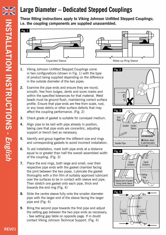
Large Diameter – Dedicated Stepped CouplingsThese fitting instructions apply to Viking Johnson Unfitted Stepped Couplings; i.e. the coupling components are supplied unassembled.
1. Viking Johnson unfitted Stepped Couplings come in two configurations (shown in Fig. 1) with the type of product being supplied depending on the difference in the outside diameter of the two pipes.
2. Examine the pipe ends and ensure they are round, smooth, free from bulges, dents and score marks and within the specified tolerances for that material. Weld beads must be ground flush, maintaining correct surface profile. Ensure that pipe ends are free from scale, rust, or any loose debris or other surface defects that may affect the coupling performance. (Fig. 2)
3. Check grade of gasket is suitable for conveyed medium.
4. Align pipe to be laid with pipe already in position, taking care that pipe ends are concentric, adjusting support or trench bed as necessary.
5. Identify and group together the different size end rings and corresponding gaskets to avoid incorrect installation.
6. To aid installation, mark both pipe ends at a distance equal to or greater than half the overall assembled width of the coupling. (Fig. 3)
7. Place the end rings, both large and small, over their respective pipe ends with the gasket chamber facing the joint between the two pipes. Lubricate the gasket thoroughly with a thin film of suitably approved lubricant over the surfaces to be in contact with sleeve and pipe, Then stretch one gasket onto each pipe, thick end towards the end ring (Fig. 4)
8. Slide the centre sleeve fully onto the smaller diameter pipe with the larger end of the sleeve facing the larger pipe end (Fig. 4)
9. Bring the second pipe towards the first pipe and adjust the setting gap between the two pipe ends as necessary, - See setting gap table on opposite page. If in doubt contact Viking Johnson Technical Support. (Fig. 4)
Fig. 5
Fig. 2
Fig. 1
Expanded Sleeve Make-up Ring Sleeve
Fig. 3
Fig. 4
REV01
INSTA
LLATION
INSTR
UC
TION
S - English
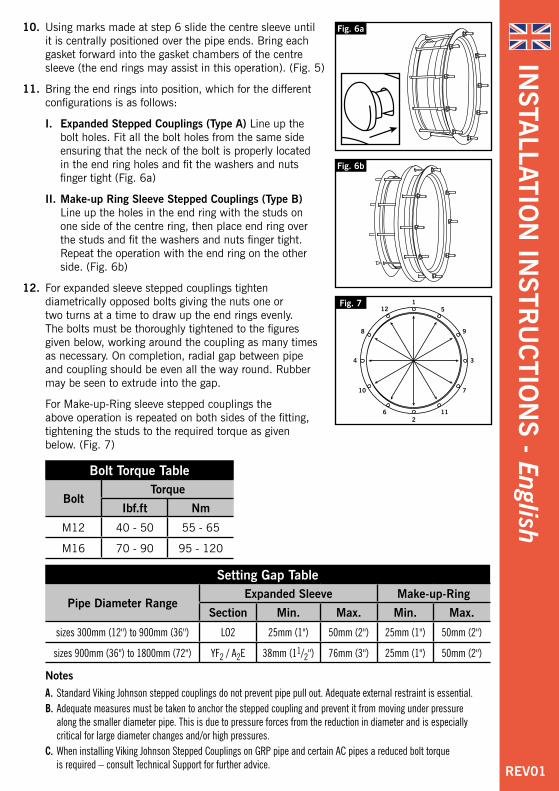
10. using marks made at step 6 slide the centre sleeve until it is centrally positioned over the pipe ends. Bring each gasket forward into the gasket chambers of the centre sleeve (the end rings may assist in this operation). (Fig. 5)
11. Bring the end rings into position, which for the different configurations is as follows:
I. Expanded Stepped Couplings (Type A) Line up the bolt holes. Fit all the bolt holes from the same side ensuring that the neck of the bolt is properly located in the end ring holes and fit the washers and nuts finger tight (Fig. 6a)
II. Make-up Ring Sleeve Stepped Couplings (Type B) Line up the holes in the end ring with the studs on one side of the centre ring, then place end ring over the studs and fit the washers and nuts finger tight. Repeat the operation with the end ring on the other side. (Fig. 6b)
12. For expanded sleeve stepped couplings tighten diametrically opposed bolts giving the nuts one or two turns at a time to draw up the end rings evenly. The bolts must be thoroughly tightened to the figures given below, working around the coupling as many times as necessary. on completion, radial gap between pipe and coupling should be even all the way round. Rubber may be seen to extrude into the gap.
For Make-up-Ring sleeve stepped couplings the above operation is repeated on both sides of the fitting, tightening the studs to the required torque as given below. (Fig. 7)
Bolt Torque Table
BoltTorque
Ibf.ft Nm
M12 40 - 50 55 - 65
M16 70 - 90 95 - 120
Fig. 6b
Fig. 7
Fig. 6a
Setting Gap Table
Pipe Diameter RangeExpanded Sleeve Make-up-Ring
Section Min. Max. Min. Max.
sizes 300mm (12") to 900mm (36") LO2 25mm (1") 50mm (2") 25mm (1") 50mm (2")
sizes 900mm (36") to 1800mm (72") YF2 / A2E 38mm (11/2") 76mm (3") 25mm (1") 50mm (2")
Notes
A. Standard Viking Johnson stepped couplings do not prevent pipe pull out. Adequate external restraint is essential.B. Adequate measures must be taken to anchor the stepped coupling and prevent it from moving under pressure
along the smaller diameter pipe. This is due to pressure forces from the reduction in diameter and is especially critical for large diameter changes and/or high pressures.
C. When installing Viking Johnson Stepped Couplings on GRP pipe and certain AC pipes a reduced bolt torque is required – consult Technical Support for further advice. REV01
INSTA
LLATION
INSTR
UC
TION
S - English
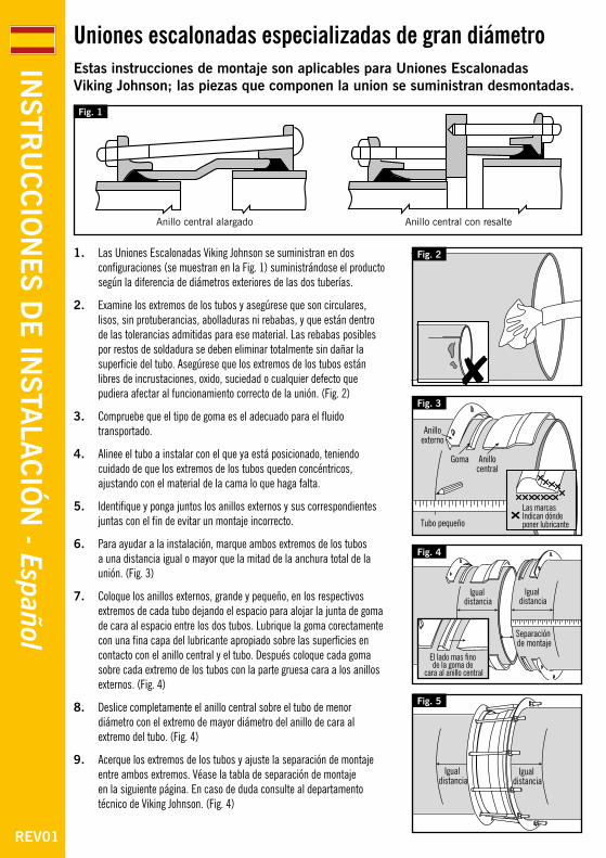
Uniones escalonadas especializadas de gran diámetroEstas instrucciones de montaje son aplicables para Uniones Escalonadas Viking Johnson; las piezas que componen la union se suministran desmontadas.
1. Las Uniones Escalonadas Viking Johnson se suministran en dos configuraciones (se muestran en la Fig. 1) suministrándose el producto según la diferencia de diámetros exteriores de las dos tuberías.
2. Examine los extremos de los tubos y asegúrese que son circulares, lisos, sin protuberancias, abolladuras ni rebabas, y que están dentro de las tolerancias admitidas para ese material. Las rebabas posibles por restos de soldadura se deben eliminar totalmente sin dañar la superficie del tubo. Asegúrese que los extremos de los tubos están libres de incrustaciones, oxido, suciedad o cualquier defecto que pudiera afectar al funcionamiento correcto de la unión. (Fig. 2)
3. Compruebe que el tipo de goma es el adecuado para el fluido transportado.
4. Alinee el tubo a instalar con el que ya está posicionado, teniendo cuidado de que los extremos de los tubos queden concéntricos, ajustando con el material de la cama lo que haga falta.
5. Identifique y ponga juntos los anillos externos y sus correspondientes juntas con el fin de evitar un montaje incorrecto.
6. Para ayudar a la instalación, marque ambos extremos de los tubos a una distancia igual o mayor que la mitad de la anchura total de la unión. (Fig. 3)
7. Coloque los anillos externos, grande y pequeño, en los respectivos extremos de cada tubo dejando el espacio para alojar la junta de goma de cara al espacio entre los dos tubos. Lubrique la goma corectamente con una fina capa del lubricante apropiado sobre las superficies en contacto con el anillo central y el tubo. Después coloque cada goma sobre cada extremo de los tubos con la parte gruesa cara a los anillos externos. (Fig. 4)
8. Deslice completamente el anillo central sobre el tubo de menor diámetro con el extremo de mayor diámetro del anillo de cara al extremo del tubo. (Fig. 4)
9. Acerque los extremos de los tubos y ajuste la separación de montaje entre ambos extremos. Véase la tabla de separación de montaje en la siguiente página. En caso de duda consulte al departamento técnico de Viking Johnson. (Fig. 4)
Fig. 5
Fig. 2
Fig. 1
Anillo central alargado Anillo central con resalte
Fig. 3
Fig. 4
REV01
INSTR
UC
CIO
NES D
E IN
STALA
CIÓ
N - Español
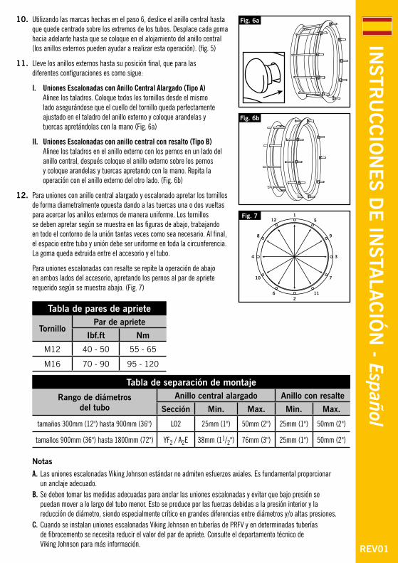
10. Utilizando las marcas hechas en el paso 6, deslice el anillo central hasta que quede centrado sobre los extremos de los tubos. Desplace cada goma hacia adelante hasta que se coloque en el alojamiento del anillo central (los anillos externos pueden ayudar a realizar esta operación). (fig. 5)
11. Lleve los anillos externos hasta su posición final, que para las diferentes configuraciones es como sigue:
I. Uniones Escalonadas con Anillo Central Alargado (Tipo A) Alinee los taladros. Coloque todos los tornillos desde el mismo lado asegurándose que el cuello del tornillo queda perfectamente ajustado en el taladro del anillo externo y coloque arandelas y tuercas apretándolas con la mano (Fig. 6a)
II. Uniones Escalonadas con anillo central con resalto (Tipo B) Alinee los taladros en el anillo externo con los pernos en un lado del anillo central, después coloque el anillo externo sobre los pernos y coloque arandelas y tuercas apretando con la mano. Repita la operación con el anillo externo del otro lado. (Fig. 6b)
12. Para uniones con anillo central alargado y escalonado apretar los tornillos de forma diametralmente opuesta dando a las tuercas una o dos vueltas para acercar los anillos externos de manera uniforme. Los tornillos se deben apretar según se muestra en las figuras de abajo, trabajando en todo el contorno de la unión tantas veces como sea necesario. Al final, el espacio entre tubo y unión debe ser uniforme en toda la circunferencia. La goma queda extruida entre el accesorio y el tubo.
Para uniones escalonadas con resalte se repite la operación de abajo en ambos lados del accesorio, apretando los pernos al par de apriete requerido según se muestra abajo. (Fig. 7)
Tabla de pares de apriete
TornilloPar de apriete
Ibf.ft Nm
M12 40 - 50 55 - 65
M16 70 - 90 95 - 120
Fig. 6b
Fig. 7
Fig. 6a
Tabla de separación de montaje
Rango de diámetros del tubo
Anillo central alargado Anillo con resalte
Sección Min. Max. Min. Max.
tamaños 300mm (12") hasta 900mm (36") LO2 25mm (1") 50mm (2") 25mm (1") 50mm (2")
tamaños 900mm (36") hasta 1800mm (72") YF2 / A2E 38mm (11/2") 76mm (3") 25mm (1") 50mm (2")
Notas
A. Las uniones escalonadas Viking Johnson estándar no admiten esfuerzos axiales. Es fundamental proporcionar un anclaje adecuado.
B. Se deben tomar las medidas adecuadas para anclar las uniones escalonadas y evitar que bajo presión se puedan mover a lo largo del tubo menor. Esto se produce por las fuerzas debidas a la presión interior y la reducción de diámetro, siendo especialmente crítico en grandes diferencias entre diámetros y/o altas presiones.
C. Cuando se instalan uniones escalonadas Viking Johnson en tuberías de PRFV y en determinadas tuberías de fibrocemento se necesita reducir el valor del par de apriete. Consulte el departamento técnico de Viking Johnson para más información. REV01
INSTR
UC
CIO
NES D
E IN
STALA
CIÓ
N - Español
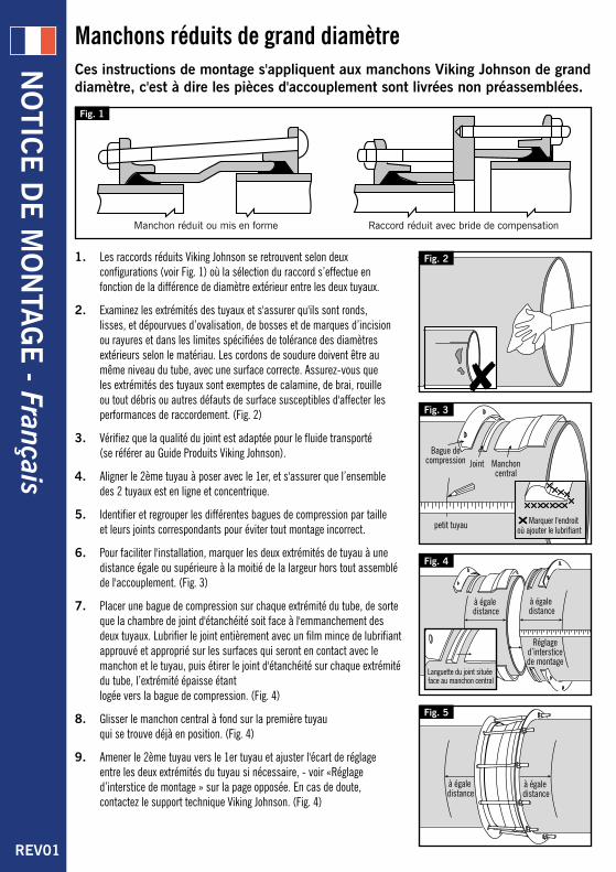
Manchons réduits de grand diamètre Ces instructions de montage s'appliquent aux manchons Viking Johnson de grand diamètre, c'est à dire les pièces d'accouplement sont livrées non préassemblées.
1. Les raccords réduits Viking Johnson se retrouvent selon deux configurations (voir Fig. 1) où la sélection du raccord s’effectue en fonction de la différence de diamètre extérieur entre les deux tuyaux.
2. Examinez les extrémités des tuyaux et s'assurer qu'ils sont ronds, lisses, et dépourvues d’ovalisation, de bosses et de marques d’incision ou rayures et dans les limites spécifiées de tolérance des diamètres extérieurs selon le matériau. Les cordons de soudure doivent être au même niveau du tube, avec une surface correcte. Assurez-vous que les extrémités des tuyaux sont exemptes de calamine, de brai, rouille ou tout débris ou autres défauts de surface susceptibles d'affecter les performances de raccordement. (Fig. 2)
3. Vérifiez que la qualité du joint est adaptée pour le fluide transporté (se référer au Guide Produits Viking Johnson).
4. Aligner le 2ème tuyau à poser avec le 1er, et s'assurer que l’ensemble des 2 tuyaux est en ligne et concentrique.
5. Identifier et regrouper les différentes bagues de compression par taille et leurs joints correspondants pour éviter tout montage incorrect.
6. Pour faciliter l'installation, marquer les deux extrémités de tuyau à une distance égale ou supérieure à la moitié de la largeur hors tout assemblé de l'accouplement. (Fig. 3)
7. Placer une bague de compression sur chaque extrémité du tube, de sorte que la chambre de joint d'étanchéité soit face à l'emmanchement des deux tuyaux. Lubrifier le joint entièrement avec un film mince de lubrifiant approuvé et approprié sur les surfaces qui seront en contact avec le manchon et le tuyau, puis étirer le joint d'étanchéité sur chaque extrémité du tube, l’extrémité épaisse étant logée vers la bague de compression. (Fig. 4)
8. Glisser le manchon central à fond sur la première tuyau qui se trouve déjà en position. (Fig. 4)
9. Amener le 2ème tuyau vers le 1er tuyau et ajuster l'écart de réglage entre les deux extrémités du tuyau si nécessaire, - voir «Réglage d’interstice de montage » sur la page opposée. En cas de doute, contactez le support technique Viking Johnson. (Fig. 4)
Fig. 5
Fig. 2
Fig. 1
Manchon réduit ou mis en forme Raccord réduit avec bride de compensation
Fig. 3
Fig. 4
REV01
NO
TICE D
E M
ON
TAG
E - Français
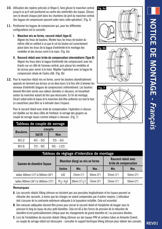
10. Utilisation des repères précisés à l'étape 6, faire glisser le manchon central jusqu'à ce qu'il soit positionné au centre des extrémités des tuyaux. Glissez vers le devant chaque joint dans les chambres de joint du manchon central (les bagues de compression peuvent aider dans cette opération). (Fig. 5)
11. Positionner les bagues de compression qui, pour les différentes configurations est la suivante:
I. Manchon mis en forme, raccord réduit (type A) Alignez les trous de boulons. Monter tous les trous de boulon du même côté en veillant à ce que le col du boulon est correctement placé dans les trous de la bague d'extrémité et le montage des rondelles et des écrous serré à la main. (Fig. 6a)
II. Raccord réduit avec bride de compensation intermédiaire (Type B) Alignez les trous dans la bague d'extrémité (de compression) avec les tirants sur un côté de l'anneau central, puis placez les rondelles et les écrous pour serrer à la main. Répéter l'opération avec la bague de compression située de l'autre côté. (Fig. 6b)
12. Pour le manchon réduit mis en forme, serrer les boulons diamétralement opposés en donnant aux écrous un ou deux tours à la fois afin d’amener les anneaux d'extrémité (bagues de compression) uniformément. Les boulons doivent être bien serrés aux valeurs données ci-dessous, en travaillant autour du manchon autant de fois que nécessaire. En fin de montage, l'écart radial entre le tuyau et le manchon doit être uniforme sur tout le tour. Le caoutchouc peut être vu à extruder dans l'espace.
Pour le raccord réduit avec bride de compensation, l'opération ci-dessus est répétée sur les deux côtés de l'embout, le serrage des goujons au couple de serrage requis comme indiqué ci-dessous. (Fig. 7)
Tableau de couple de serrage
Boulonscouple
Ibf.ft Nm
M12 40 - 50 55 - 65
M16 70 - 90 95 - 120
Fig. 6b
Fig. 7
Fig. 6a
Tableau de réglage d’interstice de montage
Gamme de diamètre TuyauxManchon élargi ou mis en forme Raccord réduit avec
bride de compensation
Section Min. Max. Min. Max.
tailles 300mm (12") à 900mm (36") LO2 25mm (1") 50mm (2") 25mm (1") 50mm (2")
tailles 900mm (36") à 1800mm (72") YF2 / A2E 38mm (11/2") 76mm (3") 25mm (1") 50mm (2")
Remarques
A. Les raccords réduits Viking Johnson ne résistent pas aux poussées longitudinales et les tuyaux peuvent se rétracter des raccords, à moins que les charges ne soient compensées par d’autres moyens. L'utilisateur doit s'assurer de la contrainte extérieure adéquate à la tuyauterie installée. Cela est essentiel.
B. Des mesures adéquates doivent être prises pour ancrer le raccord réduit et l'empêcher de bouger sous la pression le long du tuyau de plus petit diamètre. Cela est dû à des forces de pression de la réduction de diamètre et est particulièrement critique pour les changements de grand diamètre et / ou pressions élevées.
C. Lors de l'installation de raccords réduits Viking Johnson sur des tuyaux PRV et certains tubes en Amiante Ciment, un couple de serrage réduit est nécessaire - consulter le support technique Viking Johnson pour obtenir des conseils. REV01
NO
TICE D
E M
ON
TAG
E - Français
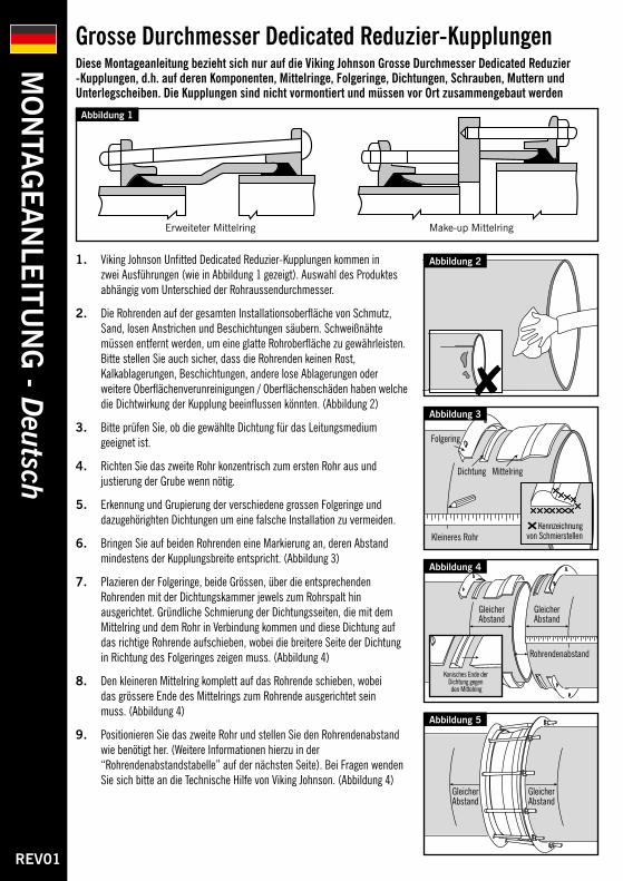
Grosse Durchmesser Dedicated Reduzier-KupplungenDiese Montageanleitung bezieht sich nur auf die Viking Johnson Grosse Durchmesser Dedicated Reduzier -Kupplungen, d.h. auf deren Komponenten, Mittelringe, Folgeringe, Dichtungen, Schrauben, Muttern und Unterlegscheiben. Die Kupplungen sind nicht vormontiert und müssen vor Ort zusammengebaut werden
1. Viking Johnson Unfitted Dedicated Reduzier-Kupplungen kommen in zwei Ausführungen (wie in Abbildung 1 gezeigt). Auswahl des Produktes abhängig vom Unterschied der Rohraussendurchmesser.
2. Die Rohrenden auf der gesamten Installationsoberfläche von Schmutz, Sand, losen Anstrichen und Beschichtungen säubern. Schweißnähte müssen entfernt werden, um eine glatte Rohroberfläche zu gewährleisten. Bitte stellen Sie auch sicher, dass die Rohrenden keinen Rost, Kalkablagerungen, Beschichtungen, andere lose Ablagerungen oder weitere Oberflächenverunreinigungen / Oberflächenschäden haben welche die Dichtwirkung der Kupplung beeinflussen könnten. (Abbildung 2)
3. Bitte prüfen Sie, ob die gewählte Dichtung für das Leitungsmedium geeignet ist.
4. Richten Sie das zweite Rohr konzentrisch zum ersten Rohr aus und justierung der Grube wenn nötig.
5. Erkennung und Grupierung der verschiedene grossen Folgeringe und dazugehörighten Dichtungen um eine falsche Installation zu vermeiden.
6. Bringen Sie auf beiden Rohrenden eine Markierung an, deren Abstand mindestens der Kupplungsbreite entspricht. (Abbildung 3)
7. Plazieren der Folgeringe, beide Grössen, über die entsprechenden Rohrenden mit der Dichtungskammer jewels zum Rohrspalt hin ausgerichtet. Gründliche Schmierung der Dichtungsseiten, die mit dem Mittelring und dem Rohr in Verbindung kommen und diese Dichtung auf das richtige Rohrende aufschieben, wobei die breitere Seite der Dichtung in Richtung des Folgeringes zeigen muss. (Abbildung 4)
8. Den kleineren Mittelring komplett auf das Rohrende schieben, wobei das grössere Ende des Mittelrings zum Rohrende ausgerichtet sein muss. (Abbildung 4)
9. Positionieren Sie das zweite Rohr und stellen Sie den Rohrendenabstand wie benötigt her. (Weitere Informationen hierzu in der “Rohrendenabstandstabelle” auf der nächsten Seite). Bei Fragen wenden Sie sich bitte an die Technische Hilfe von Viking Johnson. (Abbildung 4)
Abbildung 5
Abbildung 2
Abbildung 1
Erweiteter Mittelring Make-up Mittelring
Abbildung 3
Abbildung 4
REV01
MO
NTA
GEA
NLE
ITUN
G - D
eutsch
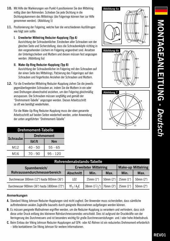
10. Mit Hilfe der Markierungen von Punkt 4 positionieren Sie den Mittelring mittig über den Rohrenden. Schieben Sie jede Dichtung in die Dichtungskammern des Mittelrings (die Folgeringe können hier zur Hilfe genommen werden). (Abbildung 5)
11. Positionierung der Folgering, welche fuer die verschiedenen Ausführugen wie folgt sein sollte:
I. Erweiterter Mittelring Reduzier-Kupplung (Typ A) Ausrichtung der Schraubenlöcher. Einstecken aller Schrauben von der gleichen Seite und Sicherstellung, dass die Schraubenköpfe richting in den vorgesehenden Löchern im Folgering angeordnet sind. Ansetzen der Unterlegscheiben und Muttern und diesen müssen fest angezogen werden. (Abbildung 6a)
II. Make-Up Ring Reduzier-Kupplung (Typ B) Ausrichtung der Schraubenlöcher im Folgering mit den Schrauben auf der einen Seite des Mittelrings, Patzierung des Folgeringes auf den Schrauben und fingerfestes Anziehen der Schrauben und Muttern.
12. Für die Erweiterten Mittelring Reduzier-Kupplung ziehen Sie die jeweils gegenüberliegenden Schrauben an, indem Sie die Muttern in ein oder zwei Drehungen abwechselnd anziehen, um den Folgering gleichmäßig anzupassen. Die Schrauben müssen sorgfältig und gemäß der “Drehmoment-Tabelle” angezogen werden. Diesen Arbeitsschritt so oft wie benötigt wiederholen.
Für die Make-Up Ring Reduzier-Kupplung muss der oben genannte Arbeitsschritt auf beiden Seiten wiederholt werden, unter Anwendung der unten angeführten “Drehmoment-Tabelle”
Drehmoment-Tabelle
Schraube Drehmoment
Ibf.ft Nm
M12 40 - 50 55 - 65
M16 70 - 90 95 - 120
Abbildung 6b
Abbildung 7
Abbildung 6a
Rohrendenabstands-Tabelle
Spannbereich/Rohraussendurchmesserbereich
Erweiteter Mittelring Make-up Mittelring
Abschnitt Min. Max. Min. Max.
Durchmesser 300mm (12") hasta 900mm (36") LO2 25mm (1") 50mm (2") 25mm (1") 50mm (2")
Durchmesser 900mm (36") hasta 1800mm (72") YF2 / A2E 38mm (11/2") 76mm (3") 25mm (1") 50mm (2")
Anmerkungen
A. Standard Viking Johnson Reduzier-Kupplungen sind nicht zugfest. Der Anwender muss sicherstellen, dass sämtliche auftretendenen axialen Zugkräfte bauseits durch geeignete Massnahmen aufgefangen werden können.
B. Es müssen geeignete Maßnahmen ergriffen werden, um die Reduzier-Kupplung zu verankern und verhindern, dass sich diese unter Druck entlang des kleineren Rohrdurchmesserendes verschiebt. Dies ist aufgrund der Druckkräfte von der Verringerung des Durchmessers und ist besonders wichtig für große Durchmesserstufungen und / oder hohe Arbeitsdruck.
C. Beim Einbau der Viking Johnson Reduzier-Kupplungen auf GFK- oder AZ-Rohren ist ein reduziertes Drehmoment erforderlich – bitte kontaktieren Sie Viking Johnson für weitere Informationen.
REV01
MO
NTA
GEA
NLE
ITUN
G - D
eutsch
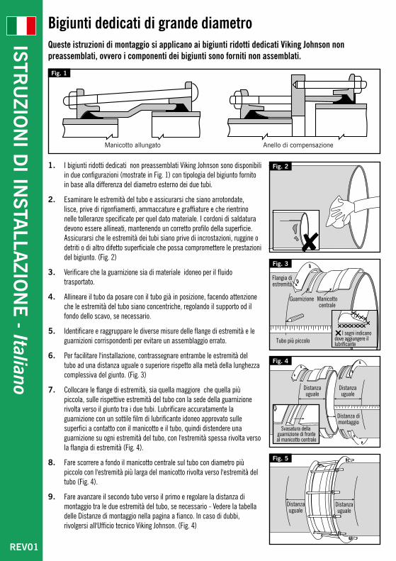
Bigiunti dedicati di grande diametroQueste istruzioni di montaggio si applicano ai bigiunti ridotti dedicati Viking Johnson non preassemblati, ovvero i componenti dei bigiunti sono forniti non assemblati.
1. I bigiunti ridotti dedicati non preassemblati Viking Johnson sono disponibili in due configurazioni (mostrate in Fig. 1) con tipologia del bigiunto fornito in base alla differenza del diametro esterno dei due tubi.
2. Esaminare le estremità del tubo e assicurarsi che siano arrotondate, lisce, prive di rigonfiamenti, ammaccature e graffiature e che rientrino nelle tolleranze specificate per quel dato materiale. I cordoni di saldatura devono essere allineati, mantenendo un corretto profilo della superficie. Assicurarsi che le estremità dei tubi siano prive di incrostazioni, ruggine o detriti o di altro difetto superficiale che possa compromettere le prestazioni del bigiunto. (Fig. 2)
3. Verificare che la guarnizione sia di materiale idoneo per il fluido trasportato.
4. Allineare il tubo da posare con il tubo già in posizione, facendo attenzione che le estremità del tubo siano concentriche, regolando il supporto od il fondo dello scavo, se necessario.
5. Identificare e raggruppare le diverse misure delle flange di estremità e le guarnizioni corrispondenti per evitare un assemblaggio errato.
6. Per facilitare l'installazione, contrassegnare entrambe le estremità del tubo ad una distanza uguale o superiore rispetto alla metà della lunghezza complessiva del giunto. (Fig. 3)
7. Collocare le flange di estremità, sia quella maggiore che quella più piccola, sulle rispettive estremità del tubo con la sede della guarnizione rivolta verso il giunto tra i due tubi. Lubrificare accuratamente la guarnizione con un sottile film di lubrificante idoneo approvato sulle superfici a contatto con il manicotto e il tubo, quindi distendere una guarnizione su ogni estremità del tubo, con l'estremità spessa rivolta verso la flangia di estremità (Fig. 4).
8. Fare scorrere a fondo il manicotto centrale sul tubo con diametro più piccolo con l'estremità più larga del manicotto rivolta verso l'estremità del tubo (Fig. 4).
9. Fare avanzare il secondo tubo verso il primo e regolare la distanza di montaggio tra le due estremità del tubo, se necessario - Vedere la tabella delle Distanze di montaggio nella pagina a fianco. In caso di dubbi, rivolgersi all'Ufficio tecnico Viking Johnson. (Fig. 4)
Fig. 5
Fig. 2
Fig. 1
Manicotto allungato Anello di compensazione
Fig. 3
Fig. 4
REV01
ISTRU
ZION
I DI IN
STALLA
ZION
E - Italiano
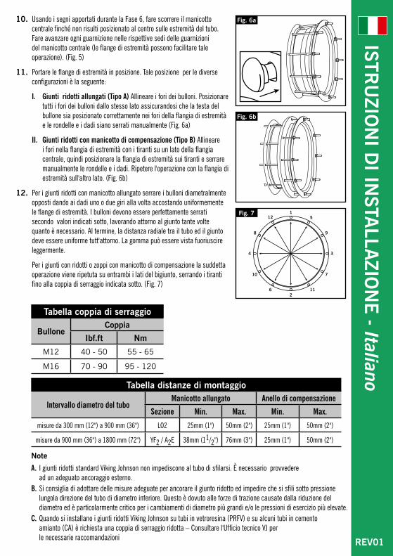
10. Usando i segni apportati durante la Fase 6, fare scorrere il manicotto centrale finché non risulti posizionato al centro sulle estremità del tubo. Fare avanzare ogni guarnizione nelle rispettive sedi delle guarnizioni del manicotto centrale (le flange di estremità possono facilitare tale operazione). (Fig. 5)
11. Portare le flange di estremità in posizione. Tale posizione per le diverse configurazioni è la seguente:
I. Giunti ridotti allungati (Tipo A) Allineare i fori dei bulloni. Posizionare tutti i fori dei bulloni dallo stesso lato assicurandosi che la testa del bullone sia posizionato correttamente nei fori della flangia di estremità e le rondelle e i dadi siano serrati manualmente (Fig. 6a)
II. Giunti ridotti con manicotto di compensazione (Tipo B) Allineare i fori nella flangia di estremità con i tiranti su un lato della flangia centrale, quindi posizionare la flangia di estremità sui tiranti e serrare manualmente le rondelle e i dadi. Ripetere l'operazione con la flangia di estremità sull'altro lato. (Fig. 6b)
12. Per i giunti ridotti con manicotto allungato serrare i bulloni diametralmente opposti dando ai dadi uno o due giri alla volta accostando uniformemente le flange di estremità. I bulloni devono essere perfettamente serrati secondo valori indicati sotto, lavorando attorno al giunto tante volte quanto è necessario. Al termine, la distanza radiale tra il tubo ed il giunto deve essere uniforme tutt'attorno. La gomma può essere vista fuoriuscire leggermente.
Per i giunti con ridotti o zoppi con manicotto di compensazione la suddetta operazione viene ripetuta su entrambi i lati del bigiunto, serrando i tiranti fino alla coppia di serraggio indicata sotto. (Fig. 7)
Tabella coppia di serraggio
BulloneCoppia
Ibf.ft Nm
M12 40 - 50 55 - 65
M16 70 - 90 95 - 120
Fig. 6b
Fig. 7
Fig. 6a
Tabella distanze di montaggio
Intervallo diametro del tuboManicotto allungato Anello di compensazione
Sezione Min. Max. Min. Max.
misure da 300 mm (12") a 900 mm (36") LO2 25mm (1") 50mm (2") 25mm (1") 50mm (2")
misure da 900 mm (36") a 1800 mm (72") YF2 / A2E 38mm (11/2") 76mm (3") 25mm (1") 50mm (2")
Note
A. I giunti ridotti standard Viking Johnson non impediscono al tubo di sfilarsi. È necessario provvedere ad un adeguato ancoraggio esterno.
B. Si consiglia di adottare delle misure adeguate per ancorare il giunto ridotto ed impedire che si sfili sotto pressione lungola direzione del tubo di diametro inferiore. Questo è dovuto alle forze di trazione causate dalla riduzione del diametro ed è particolarmente critico per i cambiamenti di diametro più grandi e/o le pressioni di esercizio più elevate.
C. Quando si installano i giunti ridotti Viking Johnson su tubi in vetroresina (PRFV) e su alcuni tubi in cemento amianto (CA) è richiesta una coppia di serraggio ridotta – Consultare l'Ufficio tecnico VJ per le necessarie raccomandazioni REV01
ISTRU
ZION
I DI IN
STALLA
ZION
E - Italiano
REV01
ИН
СТ
РУ
КЦ
ИЯ
ПО
МО
НТА
ЖУ
- РУССКИЙ
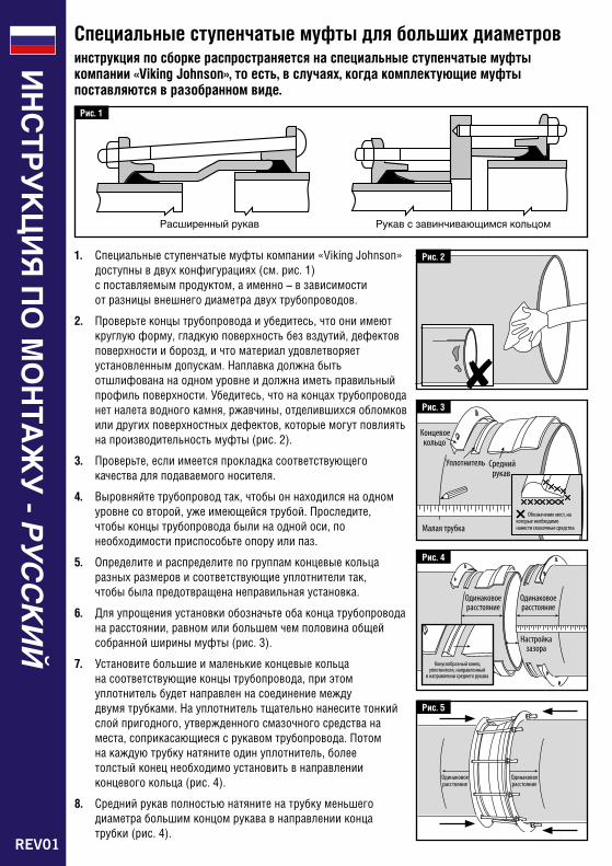
Специальные ступенчатые муфты для больших диаметров инструкция по сборке распространяется на cпециальные ступенчатые муфты компании «Viking Johnson», то есть, в случаях, когда комплектующие муфты поставляются в разобранном виде.
1. Специальные ступенчатые муфты компании «Viking Johnson» доступны в двух конфигурациях (см. рис. 1) с поставляемым продуктом, а именно – в зависимости от разницы внешнего диаметра двух трубопроводов.
2. Проверьте концы трубопровода и убедитесь, что они имеют круглую форму, гладкую поверхность без вздутий, дефектов поверхности и борозд, и что материал удовлетворяет установленным допускам. Наплавка должна быть отшлифована на одном уровне и должна иметь правильный профиль поверхности. Убедитесь, что на концах трубопровода нет налета водного камня, ржавчины, отделившихся обломков или других поверхностных дефектов, которые могут повлиять на производительность муфты (рис. 2).
3. Проверьте, если имеется прокладка соответствующего качества для подаваемого носителя.
4. Выровняйте трубопровод так, чтобы он находился на одном уровне со второй, уже имеющейся трубой. Проследите, чтобы концы трубопровода были на одной оси, по необходимости приспособьте опору или паз.
5. Определите и распределите по группам концевые кольца разных размеров и соответствующие уплотнители так, чтобы была предотвращена неправильная установка.
6. Для упрощения установки обозначьте оба конца трубопровода на расстоянии, равном или большем чем половина общей собранной ширины муфты (рис. 3).
7. Установите большие и маленькие концевые кольца на соответствующие концы трубопровода, при этом уплотнитель будет направлен на соединение между двумя трубками. На уплотнитель тщательно нанесите тонкий слой пригодного, утвержденного смазочного средства на места, соприкасающиеся с рукавом трубопровода. Потом на каждую трубку натяните один уплотнитель, более толстый конец необходимо установить в направлении концевого кольца (рис. 4).
8. Средний рукав полностью натяните на трубку меньшего диаметра большим концом рукава в направлении конца трубки (рис. 4).
Рис. 5
Рис. 2
Рис. 1
Расширенный рукав Рукав с завинчивающимся кольцом
Рис. 3
Рис. 4
REV01
ИН
СТ
РУ
КЦ
ИЯ
ПО
МО
НТА
ЖУ
- РУССКИЙ
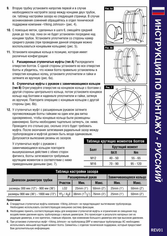
9. Вторую трубку установите напротив первой и в случае необходимости настройте зазор между концами двух трубок, см. таблицу настройки зазора на следующей странице. В случае возникновения сомнений обращайтесь в отдел технической поддержки компании «Viking Johnson» (рис. 4).
10. С помощью меток, сделанных в шаге 6, смещайте средний рукав до тех пор, пока он не будет установлен посредине над концами трубок. Установите уплотнители со стороны камер среднего рукава (при проведении данной операции можно воспользоваться концевыми кольцами) (рис. 5).
11. Установите концевые кольца в позицию, которая имеет различные конфигурации:
I. Расширенные ступенчатые муфты (тип A) Распределите отверстия болтов. С одной стороны установите во все отверстия болты и убедитесь, что ножки болта правильно установлены в отверстия концевых колец, установите уплотнители и гайки и затяните их вручную (рис. 6a).
II. Ступенчатые муфты с рукавом с завинчивающимся кольцом (тип B) Отрегулируйте отверстия на концевом кольце с болтами с другой стороны центрального кольца, потом установите концевое кольцо над болтами и наденеьте уплотнители и гайки, затянув их вручную. Повторите операцию с концевым кольцом с другой стороны (рис. 6b).
12. У ступенчатых муфт с расширенным рукавом затяните противолежащие болты гайками на один или два витка одновременно, чтобы концевые кольца были размещены равномерно. Болты необходимо тщательно затянуть, см. ниже. Проводите это столько раз, сколько этого будет требовать муфта. После окончания затягивания радиальный зазор между трубопроводом и муфтой должен быть везде одинаковым. Допускается вылезание резины из зазоров.
У ступенчатых муфт с рукавом с завинчивающимся кольцом повторите вышеуказанные действия с обеих сторон фитинга, болты затягиваются требуемым крутящим моментом в соответствии с ниже приведенными данными (рис. 7).
Таблица крутящих моментов болтов
Болт Крутящий момент
Ibf.ft Nm
M12 40 - 50 55 - 65
M16 70 - 90 95 - 120
Рис. 6b
Рис. 7
Рис. 6a
Таблица настройки зазора
Диапазон диаметров трубки Расширенный рукав Завинчивающееся кольцо
Участок Мин. Макс. Мин. Макс.
размеры 300 мм (12") - 900 мм (36") LO2 25mm (1") 50mm (2") 25mm (1") 50mm (2")
размеры 900 мм (36") - 1800 мм (72") YF2 / A2E 38mm (11/2") 76mm (3") 25mm (1") 50mm (2")
ПримечанияA. Стандартные ступенчатые муфты компании «Viking Johnson» не предотвращают вытягивание трубопровода.
Необходимо использовать соответствующую внешнюю систему фиксации. B. Необходимо принять соответствующие меры для анкеровки ступенчатой муфты и ограничения ее смещения под
воздействием давления вдоль трубопровода с малым диаметром. Это происходит в результате напорных сил из редукции диаметра, и оно критично, главным образом, при изменении большого диаметра или при высоком давлении.
C. При установке ступенчатых муфт «Viking Johnson» на трубопровод GRP и некоторые трубопроводы AC необходимо использовать меньший крутящий момент болта. Свяжитесь с отделом технической поддержки, который предоставит Вам дополнительную информацию.
www.cranebsu.com
46-48 Wilbury Way HitcHin, HertfordsHire sG4 0ud. uK
telepHone: +44 (0)1462 443322 fax: +44 (0)1462 443311 email: [email protected]
DR7292_01_2015
Every effort has been made to ensure that the information contained in this publication is accurate at the time of publishing. Crane Ltd assumes no responsibility or liability for typographical errors or omissions or for any misinterpretation of the information within the publication and reserves the right to change without notice.
Se han extremado las precauciones para asegurar que la información contenida en este catálogo sea exacta en el momento de su publicación. Crane Ltd no acepta ninguna responsabilidad por errores tipográficos, omisiones o cualquier interpretación errónea de la información contenida en la publicación y se reserva el derecho de cambiarla sin previo aviso.
Toutes les précautions ont été prises pour vérifier l'exactitude des informations figurant aux présentes au moment de la publication. Crane Ltd n'accepte aucune responsabilité ni obligation relatives à des erreurs typographiques ou omissions ou à une interprétation erronée des informations figurant dans la publication et se réserve le droit de la modifier sans préavis.
Es wurden alle erforderlichen Massnahmen getroffen, um zu gewährleisten, dass zum Zeitpunkt der Herausgabe alle Informationen in dieser Publikation akurat und zutreffend sind. Crane LTD übernimmt keine Verantwortung oder Haftung für typografische Fehler, Auslassungen oder für etwaige Fehlinterpretationen innerhalb dieser Publikation und behält sich das Recht vor, Aenderungen jederzeit und ohne vorherige Ankündigung vorzunehmen.
È stato fatto ogni sforzo possibile per assicurare l'accuratezza delle informazioni qui presentate alla data di pubblicazione. Crane Ltd non si assume alcuna responsabilità per eventuali errori tipografici, omissioni o per interpretazioni errate delle informazioni presentate e si riserva il diritto di modificarle senza alcun avviso.
Все наши усилия были направлены на то, чтобы информация, содержащаяся в настоящей публикации, являлась точной на момент ее издания. “Crane Ltd” не несет ответственности за типографские ошибки или упущения в виде неправильного толкования информации в публикации, и оставляет за собой право вносить любые изменения без предварительного уведомления.
To visit our Video Library go to: Para visitar nuestra videoteca consulte: Pour visiter notre bibliothèque vidéos se rendre à : Besuch unserer Videothek über: Per visitare la nostra videoteca andare su: Чтобы войти в нашу Видеотеку воспользуйтесь ссылкой: http://www.youtube.com/user/CraneBSU
ISO 14001 • EMS 51874 ISO 9001 • FM 00311