Embed Size (px)
Citation preview
LARGE DIAMETER CCPs: FREQUENCY, PRESSURE, GAS MIXTURE, GEOMETRY
– THEY ALL MATTER*
Yang YangIowa State University, IA 50010 USA
Mark J. KushnerUniversity of Michigan
Ann Arbor, MI 48109 USA [email protected]
http://uigelz.eecs.umich.edu
May 2009
* Work supported by SRC, Applied Materials, TEL Inc.
AGENDA
RFWKSHP09
University of MichiganInstitute for Plasma Science & Engr.
• Wave effects in capacitively coupled plasmas• Scaling Large Area CCPs
• Frequencies• Pressures• Gas Mixtures
• What about 450 mm?• Segmented Electrodes?• Concluding Remarks
MULTI-FREQUENCY PLASMA ETCHING REACTORS
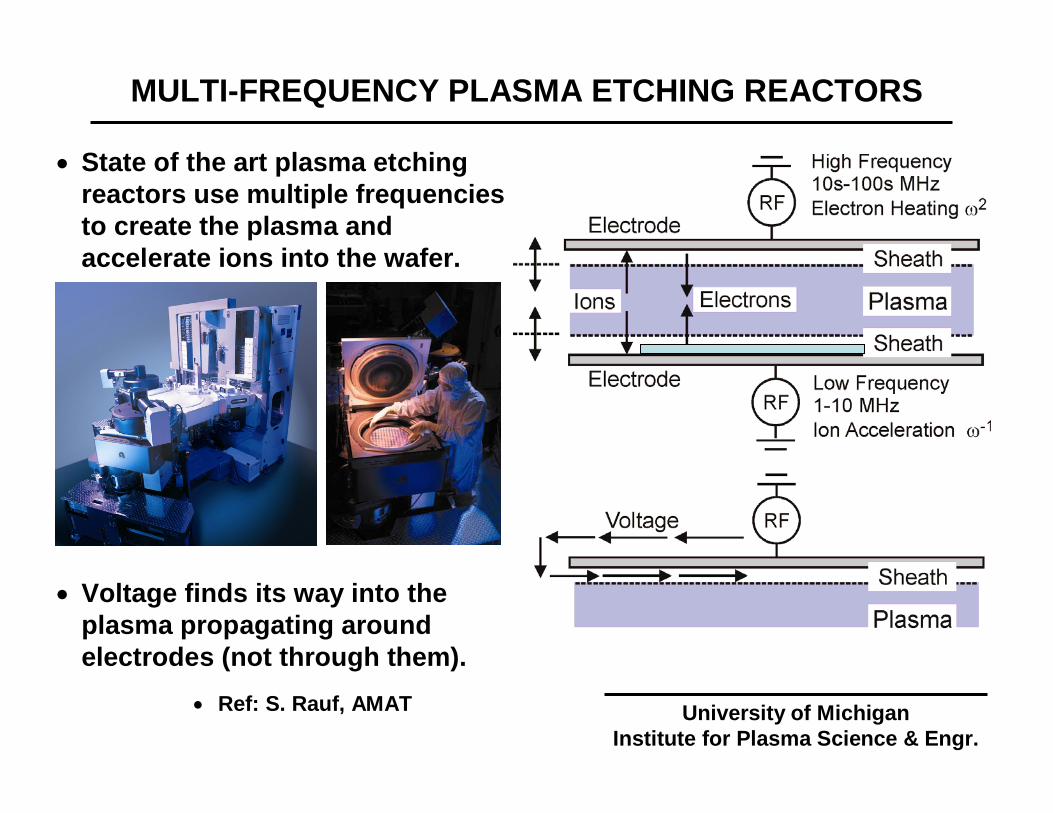
• State of the art plasma etching reactors use multiple frequencies to create the plasma and accelerate ions into the wafer.
• Voltage finds its way into the plasma propagating around electrodes (not through them).
• Ref: S. Rauf, AMAT University of MichiganInstitute for Plasma Science & Engr.
WAVE EFFECTS CHALLENGE SCALING
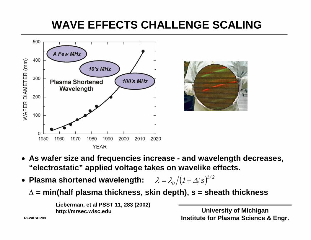
Lieberman, et al PSST 11, 283 (2002)http://mrsec.wisc.edu
RFWKSHP09
University of MichiganInstitute for Plasma Science & Engr.
• As wafer size and frequencies increase - and wavelength decreases, “electrostatic” applied voltage takes on wavelike effects.
• Plasma shortened wavelength: ∆ = min(half plasma thickness, skin depth), s = sheath thickness
( ) 2/10 s1 ∆λλ +=
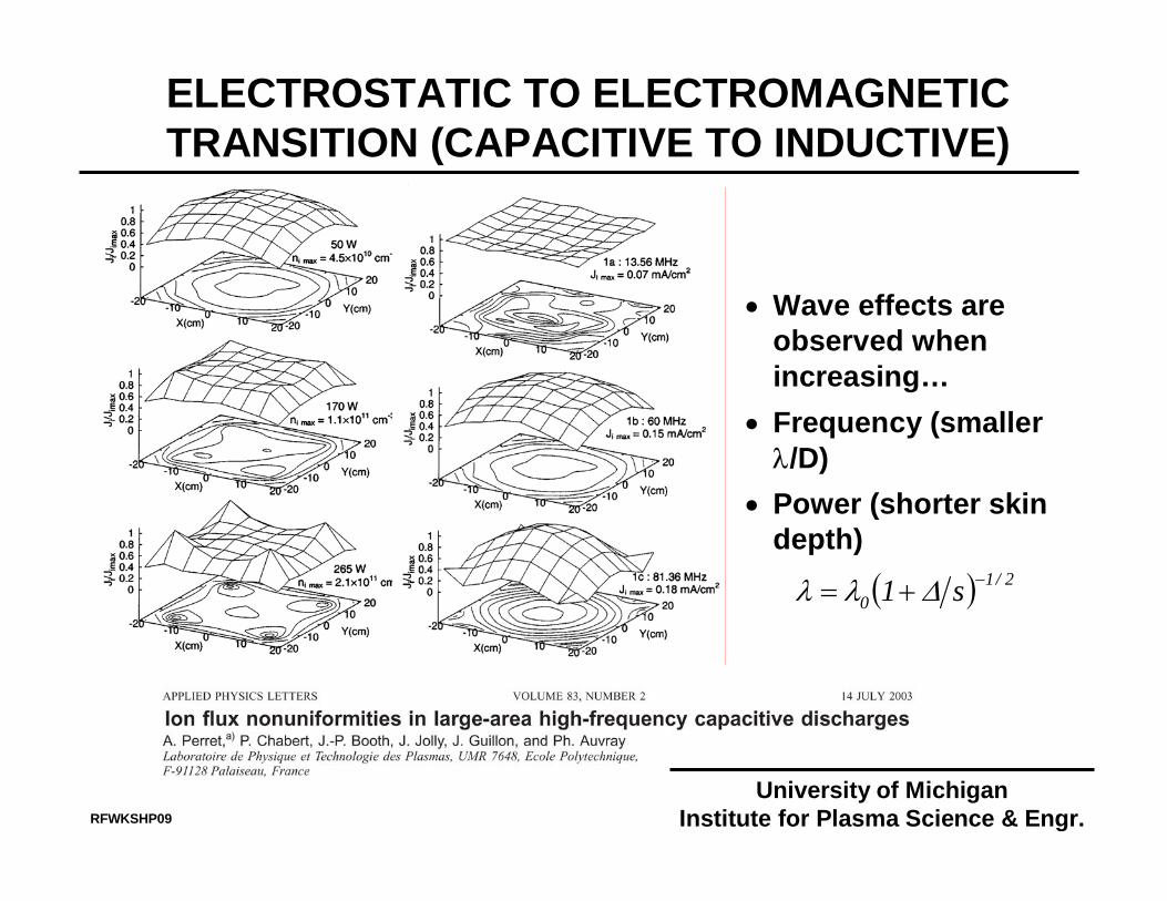
ELECTROSTATIC TO ELECTROMAGNETIC TRANSITION (CAPACITIVE TO INDUCTIVE)
RFWKSHP09
University of MichiganInstitute for Plasma Science & Engr.
• Wave effects are observed when increasing…
• Frequency (smaller λ/D)
• Power (shorter skin depth)
( ) 2/10 s1 −+= ∆λλ
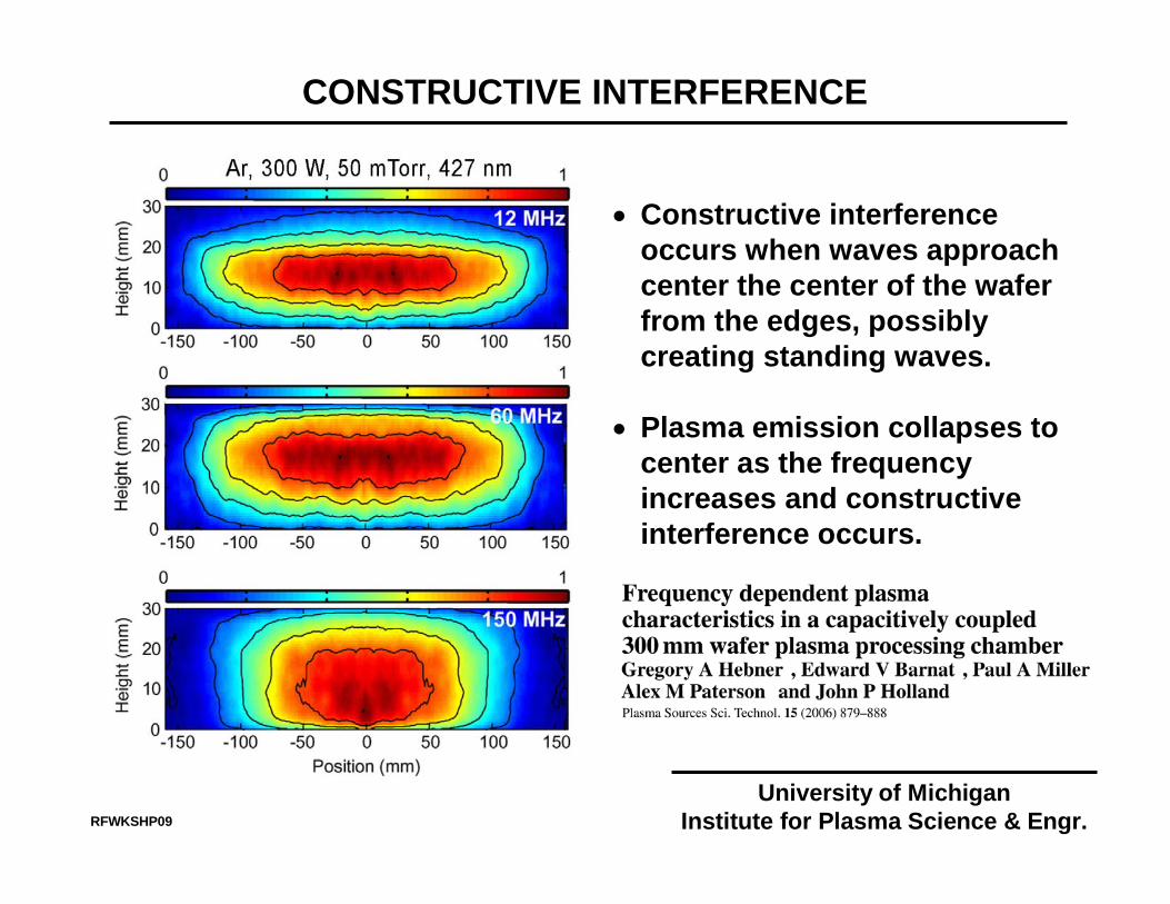
CONSTRUCTIVE INTERFERENCE
• Constructive interference occurs when waves approach center the center of the wafer from the edges, possibly creating standing waves.
• Plasma emission collapses to center as the frequency increases and constructive interference occurs.
University of MichiganInstitute for Plasma Science & Engr.RFWKSHP09
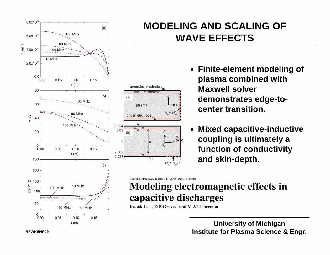
MODELING AND SCALING OF WAVE EFFECTS
• Finite-element modeling of plasma combined with Maxwell solver demonstrates edge-to-center transition.
• Mixed capacitive-inductive coupling is ultimately a function of conductivity and skin-depth.
University of MichiganInstitute for Plasma Science & Engr.RFWKSHP09

SOURCES OF NON-UNIFORMITY
University of MichiganInstitute for Plasma Science & Engr.RFWKSHP09
J. Phys. D 40 (2007)
GOALS: SCALING OF CCPS TO LARGE AREAS
• Develop a computational infrastructure for self-consistent and general implementation of Maxwell’s equations into a plasma equipment model.
• Investigate sources of non-uniformities under industrial processing conditions.• Feeds, materials, geometries• Gas mixture• Frequency• Pressure
• Look forward to challenges of 450 mm scaling and new technologies to enable scaling.
RFWKSHP09
University of MichiganInstitute for Plasma Science & Engr.

HYBRID PLASMA EQUIPMENT MODEL (HPEM)
• Electron Energy Transport Module:• Electron Monte Carlo Simulation
provides EEDs of bulk electrons• Separate MCS used for secondary,
sheath accelerated electrons • Fluid Kinetics Module:
• Heavy particle and electron continuity, momentum, energy
• Maxwell’s Equation• Plasma Chemistry Monte Carlo Module:
• IEADs onto wafer
RFWKSHP09
E, N
Fluid Kinetics ModuleFluid equations
(continuity, momentum,
energy)Maxwell
Equations
Te,S,μ
Electron Energy Transport
Module
Plasma Chemistry Monte Carlo
ModuleUniversity of Michigan
Institute for Plasma Science & Engr.
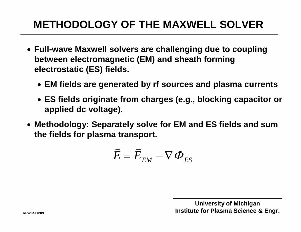
• Full-wave Maxwell solvers are challenging due to coupling between electromagnetic (EM) and sheath forming electrostatic (ES) fields.
• EM fields are generated by rf sources and plasma currents
• ES fields originate from charges (e.g., blocking capacitor or applied dc voltage).
• Methodology: Separately solve for EM and ES fields and sum the fields for plasma transport.
ESEMEE Φ∇−=vv
METHODOLOGY OF THE MAXWELL SOLVER
RFWKSHP09
University of MichiganInstitute for Plasma Science & Engr.
tH
rE
zE zr
∂∂
−=∂∂
−∂∂ θµ0
tEJ
zH r
rr ∂∂
+=∂∂
− εεθ0
( )t
EJr
rHr
zrz ∂∂
+=∂
∂ εεθ0
1
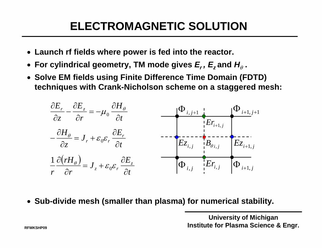
• Launch rf fields where power is fed into the reactor. • For cylindrical geometry, TM mode gives Er , Ez and Hθ . • Solve EM fields using Finite Difference Time Domain (FDTD)
techniques with Crank-Nicholson scheme on a staggered mesh:
• Sub-divide mesh (smaller than plasma) for numerical stability.
ji ,Φ
1,1 ++Φ ji
ji ,1+ΦjiEr ,
jiEr ,1+
jiEz , jiEz ,1+jiB ,θ
1, +Φ ji
ELECTROMAGNETIC SOLUTION
RFWKSHP09
University of MichiganInstitute for Plasma Science & Engr.
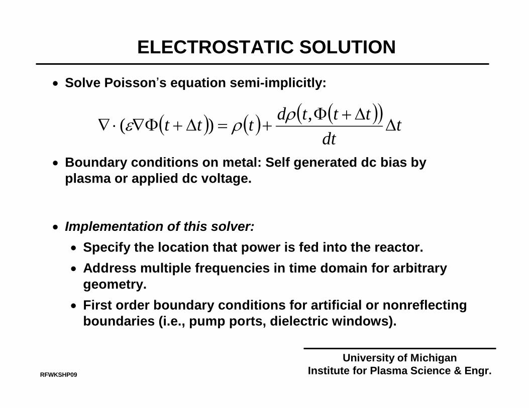
• Solve Poisson’s equation semi-implicitly:
• Boundary conditions on metal: Self generated dc bias by plasma or applied dc voltage.
• Implementation of this solver:• Specify the location that power is fed into the reactor.• Address multiple frequencies in time domain for arbitrary
geometry.• First order boundary conditions for artificial or nonreflecting
boundaries (i.e., pump ports, dielectric windows).
( ) ( ) ( )( ) tdt
tttdttt ∆∆+Φ
+=∆+Φ∇⋅∇,)( ρρε
ELECTROSTATIC SOLUTION
RFWKSHP09
University of MichiganInstitute for Plasma Science & Engr.
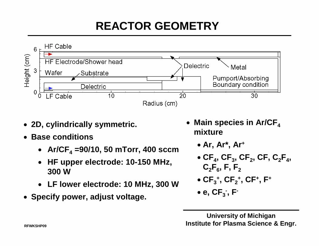
REACTOR GEOMETRY
• 2D, cylindrically symmetric. • Base conditions
• Ar/CF4 =90/10, 50 mTorr, 400 sccm• HF upper electrode: 10-150 MHz,
300 W• LF lower electrode: 10 MHz, 300 W
• Specify power, adjust voltage.
RFWKSHP09
• Main species in Ar/CF4 mixture•Ar, Ar*, Ar+
•CF4, CF3, CF2, CF, C2F4, C2F6, F, F2
•CF3+, CF2
+, CF+, F+
• e, CF3-, F-
University of MichiganInstitute for Plasma Science & Engr.
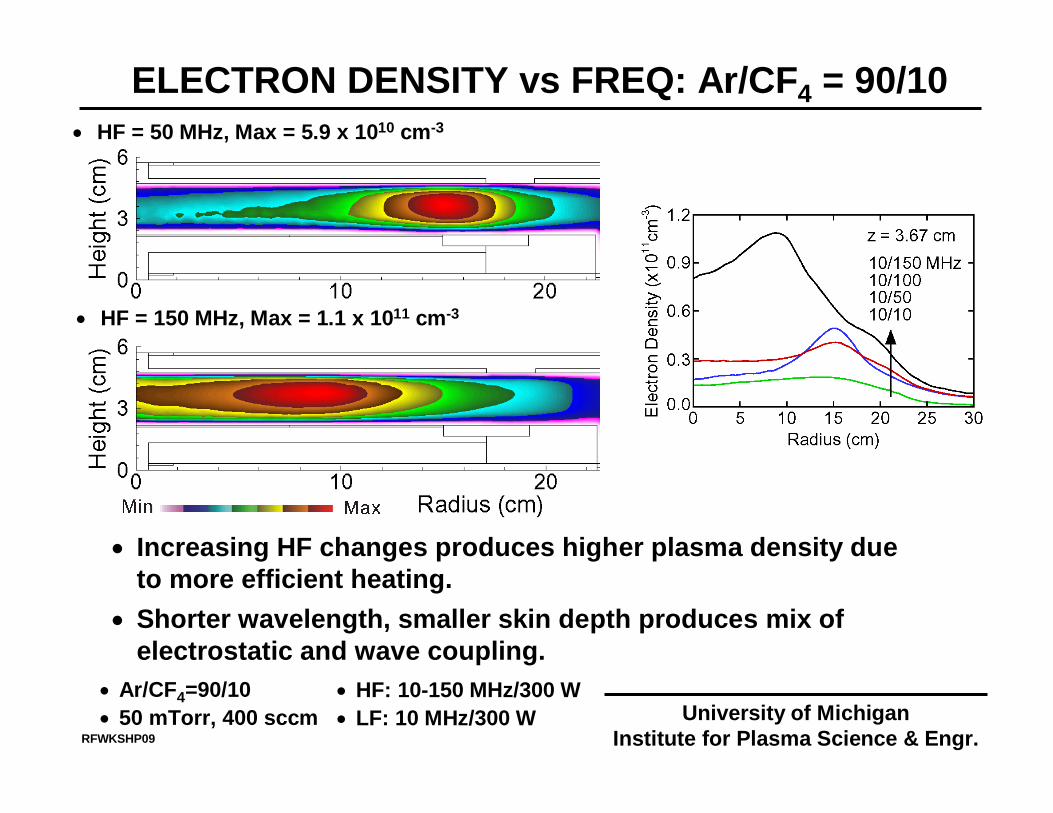
ELECTRON DENSITY vs FREQ: Ar/CF4 = 90/10
• Increasing HF changes produces higher plasma density due to more efficient heating.
• Shorter wavelength, smaller skin depth produces mix of electrostatic and wave coupling.
• HF = 150 MHz, Max = 1.1 x 1011 cm-3
• HF = 50 MHz, Max = 5.9 x 1010 cm-3
• Ar/CF4=90/10• 50 mTorr, 400 sccm
• HF: 10-150 MHz/300 W• LF: 10 MHz/300 W University of Michigan
Institute for Plasma Science & Engr.RFWKSHP09
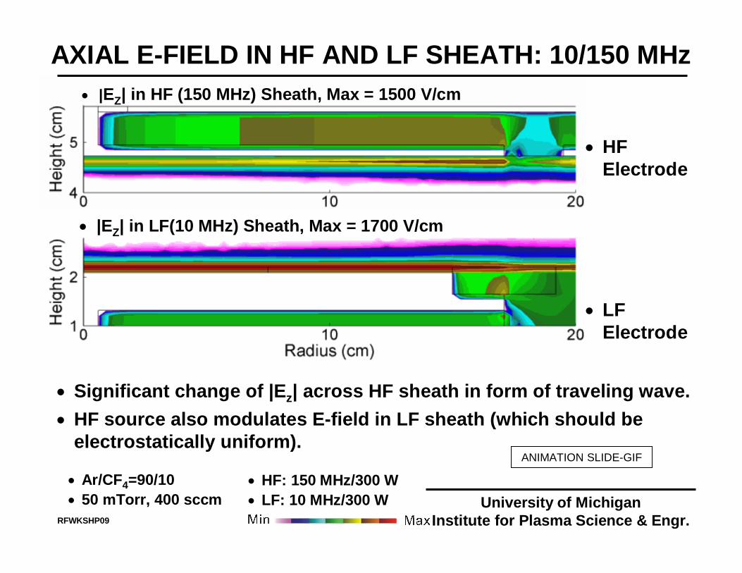
AXIAL E-FIELD IN HF AND LF SHEATH: 10/150 MHz
• |EZ| in LF(10 MHz) Sheath, Max = 1700 V/cm
• Significant change of |Ez| across HF sheath in form of traveling wave.• HF source also modulates E-field in LF sheath (which should be
electrostatically uniform).
• |EZ| in HF (150 MHz) Sheath, Max = 1500 V/cm
• Ar/CF4=90/10• 50 mTorr, 400 sccm
• HF: 150 MHz/300 W• LF: 10 MHz/300 W
RFWKSHP09
• HF Electrode
• LF Electrode
University of MichiganInstitute for Plasma Science & Engr.
ANIMATION SLIDE-GIF
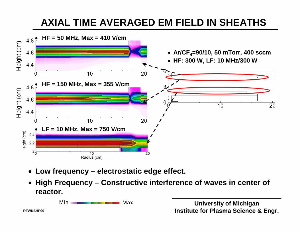
AXIAL TIME AVERAGED EM FIELD IN SHEATHS• HF = 50 MHz, Max = 410 V/cm
• HF = 150 MHz, Max = 355 V/cm
• Low frequency – electrostatic edge effect.• High Frequency – Constructive interference of waves in center of
reactor.
• Ar/CF4=90/10, 50 mTorr, 400 sccm• HF: 300 W, LF: 10 MHz/300 W
RFWKSHP09
University of MichiganInstitute for Plasma Science & Engr.
• LF = 10 MHz, Max = 750 V/cm
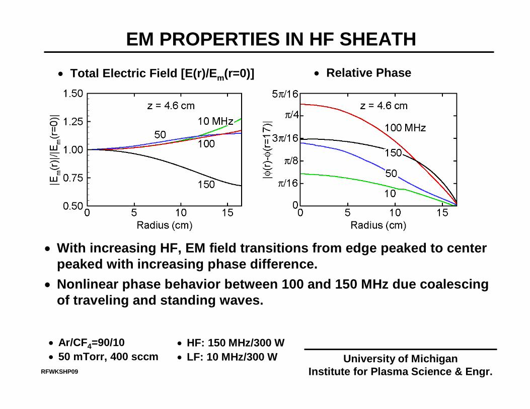
EM PROPERTIES IN HF SHEATH
• With increasing HF, EM field transitions from edge peaked to center peaked with increasing phase difference.
• Nonlinear phase behavior between 100 and 150 MHz due coalescing of traveling and standing waves.
• Total Electric Field [E(r)/Em(r=0)] • Relative Phase
• Ar/CF4=90/10• 50 mTorr, 400 sccm
• HF: 150 MHz/300 W• LF: 10 MHz/300 W University of Michigan
Institute for Plasma Science & Engr.RFWKSHP09
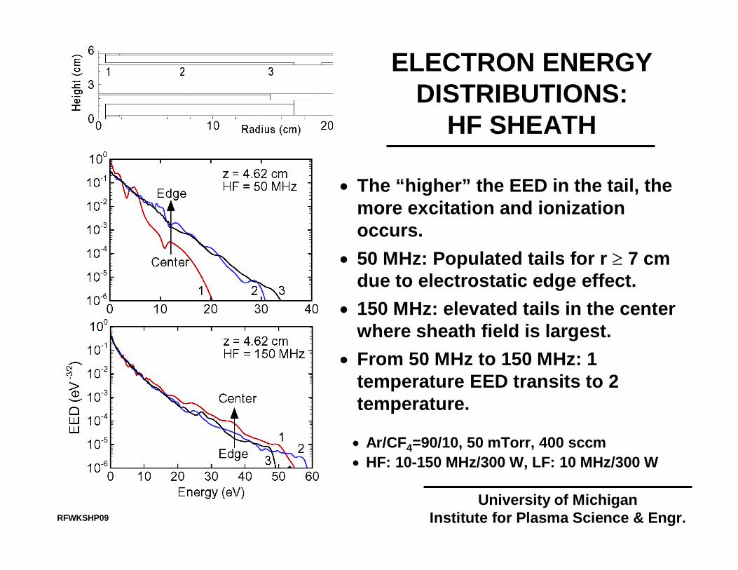
ELECTRON ENERGYDISTRIBUTIONS:
HF SHEATH
• Ar/CF4=90/10, 50 mTorr, 400 sccm• HF: 10-150 MHz/300 W, LF: 10 MHz/300 W
• The “higher” the EED in the tail, the more excitation and ionization occurs.
• 50 MHz: Populated tails for r ≥ 7 cmdue to electrostatic edge effect.
• 150 MHz: elevated tails in the center where sheath field is largest.
• From 50 MHz to 150 MHz: 1 temperature EED transits to 2 temperature.
RFWKSHP09
University of MichiganInstitute for Plasma Science & Engr.
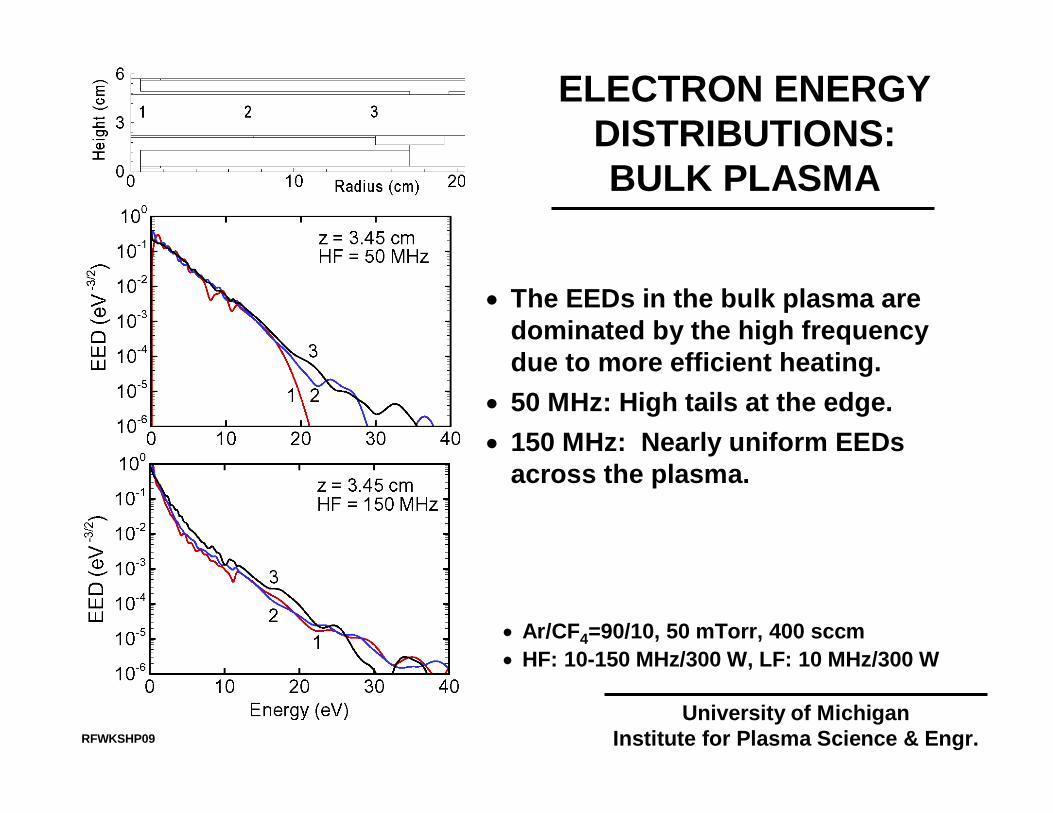
• Ar/CF4=90/10, 50 mTorr, 400 sccm• HF: 10-150 MHz/300 W, LF: 10 MHz/300 W
• The EEDs in the bulk plasma are dominated by the high frequency due to more efficient heating.
• 50 MHz: High tails at the edge.• 150 MHz: Nearly uniform EEDs
across the plasma.
RFWKSHP09
University of MichiganInstitute for Plasma Science & Engr.
ELECTRON ENERGYDISTRIBUTIONS:BULK PLASMA
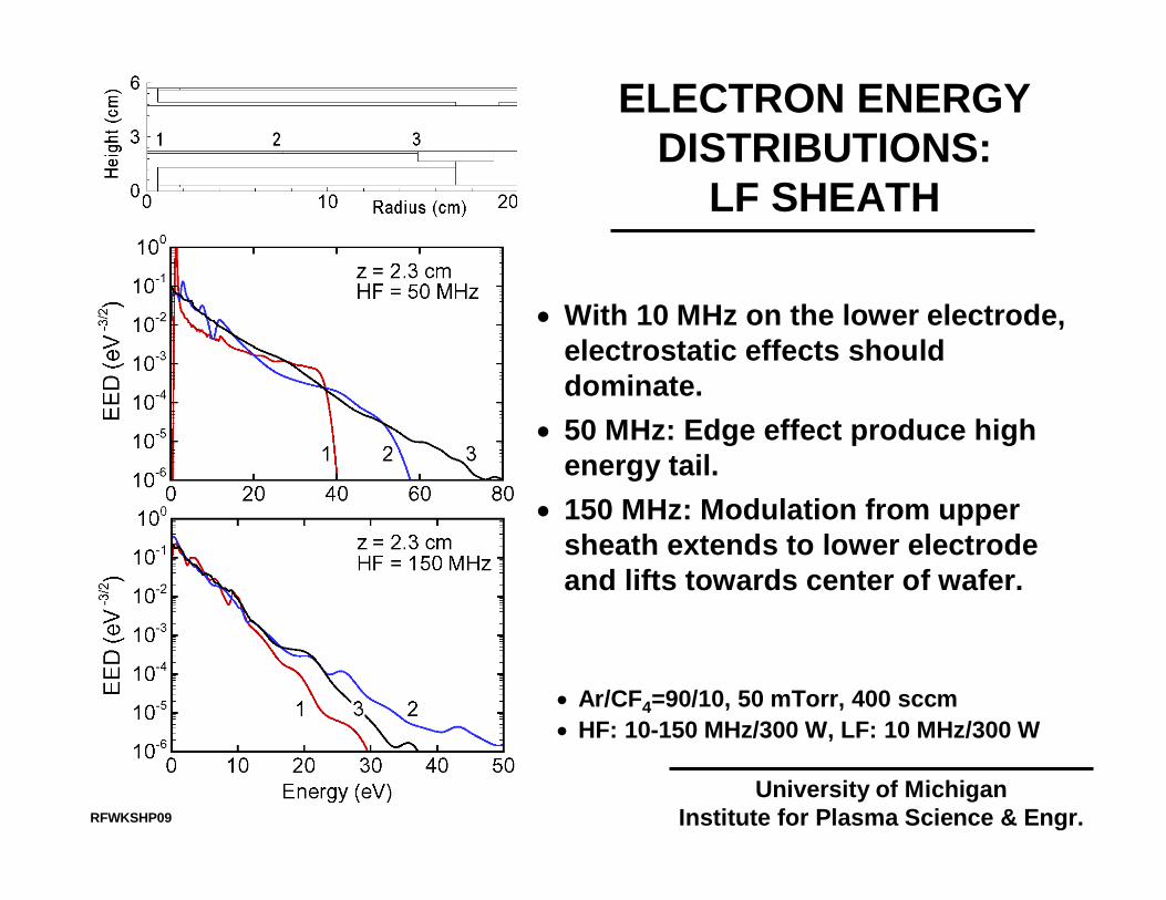
• Ar/CF4=90/10, 50 mTorr, 400 sccm• HF: 10-150 MHz/300 W, LF: 10 MHz/300 W
• With 10 MHz on the lower electrode, electrostatic effects should dominate.
• 50 MHz: Edge effect produce high energy tail.
• 150 MHz: Modulation from upper sheath extends to lower electrode and lifts towards center of wafer.
RFWKSHP09
University of MichiganInstitute for Plasma Science & Engr.
ELECTRON ENERGYDISTRIBUTIONS:
LF SHEATH
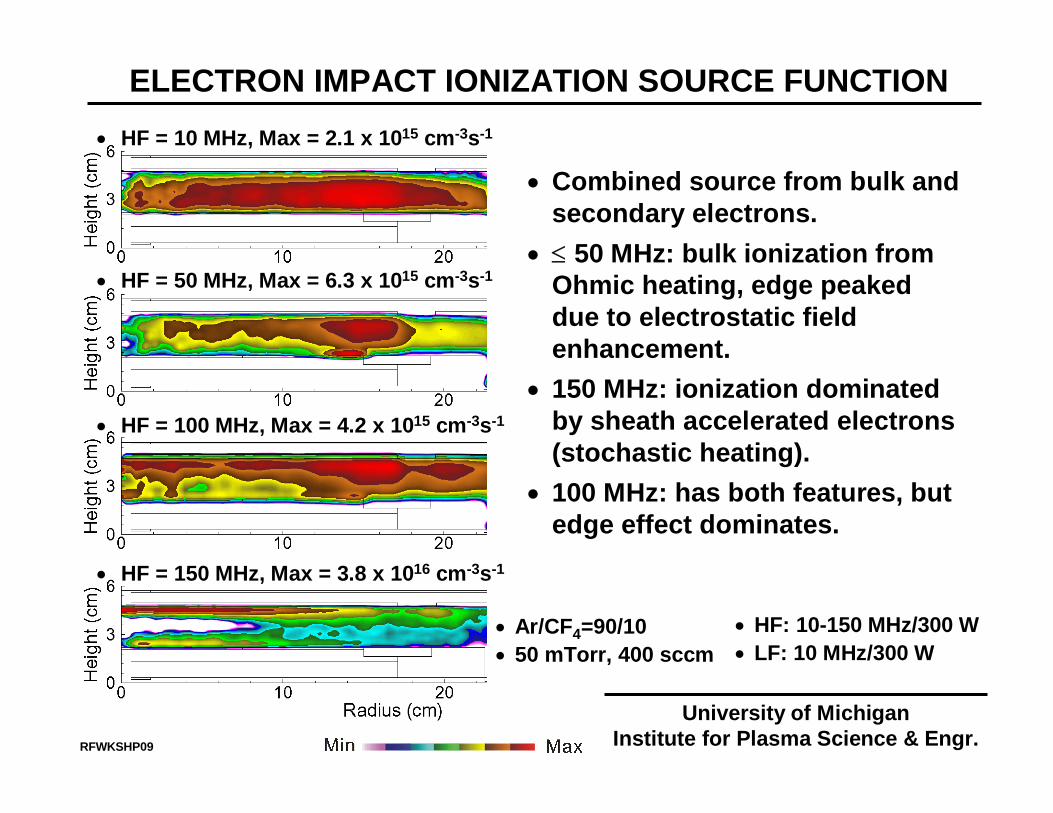
ELECTRON IMPACT IONIZATION SOURCE FUNCTION• HF = 10 MHz, Max = 2.1 x 1015 cm-3s-1
• HF = 50 MHz, Max = 6.3 x 1015 cm-3s-1
• HF = 100 MHz, Max = 4.2 x 1015 cm-3s-1
• HF = 150 MHz, Max = 3.8 x 1016 cm-3s-1
RFWKSHP09
• Combined source from bulk and secondary electrons.
• ≤ 50 MHz: bulk ionization from Ohmic heating, edge peaked due to electrostatic field enhancement.
• 150 MHz: ionization dominated by sheath accelerated electrons (stochastic heating).
• 100 MHz: has both features, but edge effect dominates.
• Ar/CF4=90/10• 50 mTorr, 400 sccm
• HF: 10-150 MHz/300 W• LF: 10 MHz/300 W
University of MichiganInstitute for Plasma Science & Engr.
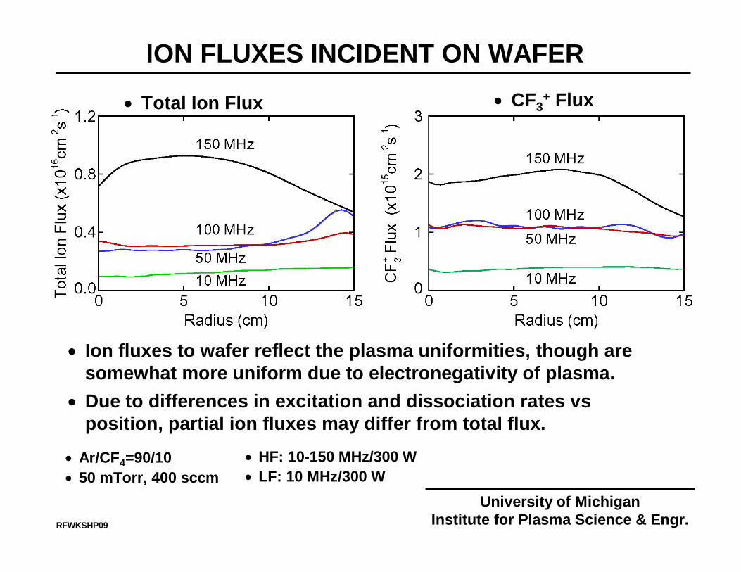
ION FLUXES INCIDENT ON WAFER
RFWKSHP09
• Ar/CF4=90/10• 50 mTorr, 400 sccm
• Ion fluxes to wafer reflect the plasma uniformities, though are somewhat more uniform due to electronegativity of plasma.
• Due to differences in excitation and dissociation rates vsposition, partial ion fluxes may differ from total flux.
• CF3+ Flux
• HF: 10-150 MHz/300 W• LF: 10 MHz/300 W
• Total Ion Flux
University of MichiganInstitute for Plasma Science & Engr.
Center Edge
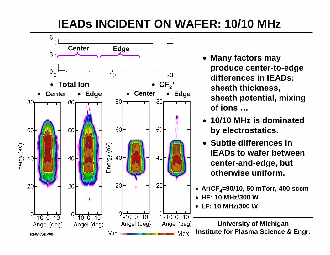
IEADs INCIDENT ON WAFER: 10/10 MHz
RFWKSHP09
• Total Ion • CF3+
• Center • Center• Edge • Edge
• Ar/CF4=90/10, 50 mTorr, 400 sccm• HF: 10 MHz/300 W• LF: 10 MHz/300 W
• Many factors may produce center-to-edge differences in IEADs: sheath thickness, sheath potential, mixing of ions …
• 10/10 MHz is dominated by electrostatics.
• Subtle differences in IEADs to wafer between center-and-edge, but otherwise uniform.
University of MichiganInstitute for Plasma Science & Engr.
Center Edge
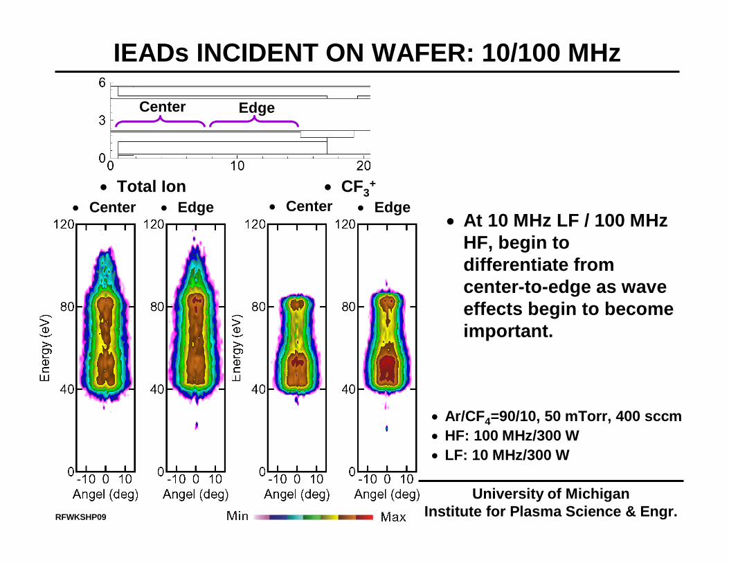
IEADs INCIDENT ON WAFER: 10/100 MHz
RFWKSHP09
• Total Ion • CF3+
• Center • Center• Edge • Edge
• Ar/CF4=90/10, 50 mTorr, 400 sccm• HF: 100 MHz/300 W• LF: 10 MHz/300 W
• At 10 MHz LF / 100 MHz HF, begin to differentiate from center-to-edge as wave effects begin to become important.
University of MichiganInstitute for Plasma Science & Engr.
Center Edge
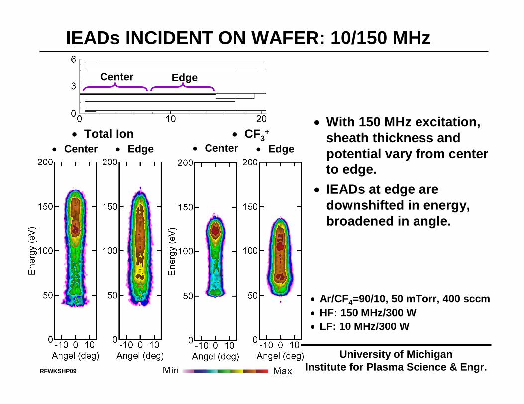
IEADs INCIDENT ON WAFER: 10/150 MHz
RFWKSHP09
• Total Ion • CF3+
• Center • Center• Edge • Edge
• With 150 MHz excitation, sheath thickness and potential vary from center to edge.
• IEADs at edge are downshifted in energy, broadened in angle.
• Ar/CF4=90/10, 50 mTorr, 400 sccm• HF: 150 MHz/300 W• LF: 10 MHz/300 W
University of MichiganInstitute for Plasma Science & Engr.
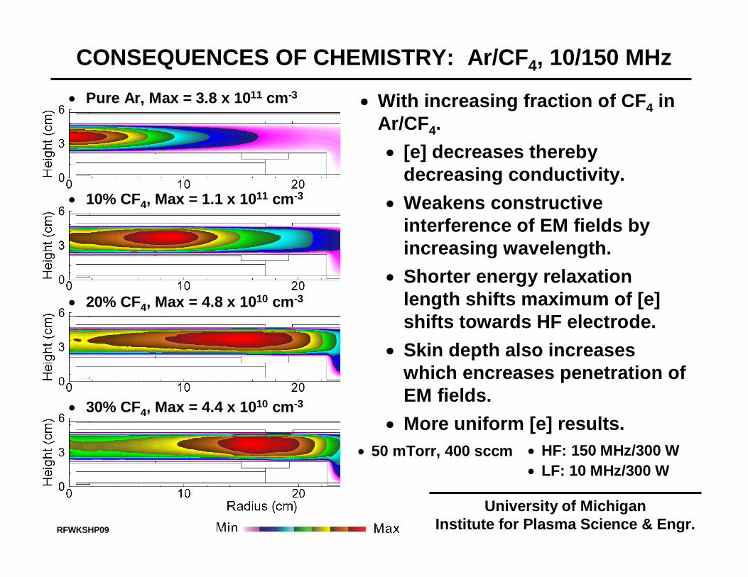
CONSEQUENCES OF CHEMISTRY: Ar/CF4, 10/150 MHz• Pure Ar, Max = 3.8 x 1011 cm-3
• 10% CF4, Max = 1.1 x 1011 cm-3
• 20% CF4, Max = 4.8 x 1010 cm-3
• 30% CF4, Max = 4.4 x 1010 cm-3
• 50 mTorr, 400 sccm • HF: 150 MHz/300 W• LF: 10 MHz/300 W
• With increasing fraction of CF4 in Ar/CF4. • [e] decreases thereby
decreasing conductivity.• Weakens constructive
interference of EM fields by increasing wavelength.
• Shorter energy relaxation length shifts maximum of [e] shifts towards HF electrode.
• Skin depth also increases which encreases penetration of EM fields.
• More uniform [e] results.
RFWKSHP09
University of MichiganInstitute for Plasma Science & Engr.

ION FLUXES TO WAFER: Ar/CF4 10/150 MHz
RFWKSHP09_22
• 50 mTorr, 400 sccm
• Uniformity of ion fluxes can be tuned with chemistry, which ultimate tunes the conductivity.
• Strong 2nd order effect with changes in EEDF.
• CF3+ Flux• Total Ion Flux
• HF: 150 MHz/300 W• LF: 10 MHz/300 W
University of MichiganInstitute for Plasma Science & Engr.
Center Edge
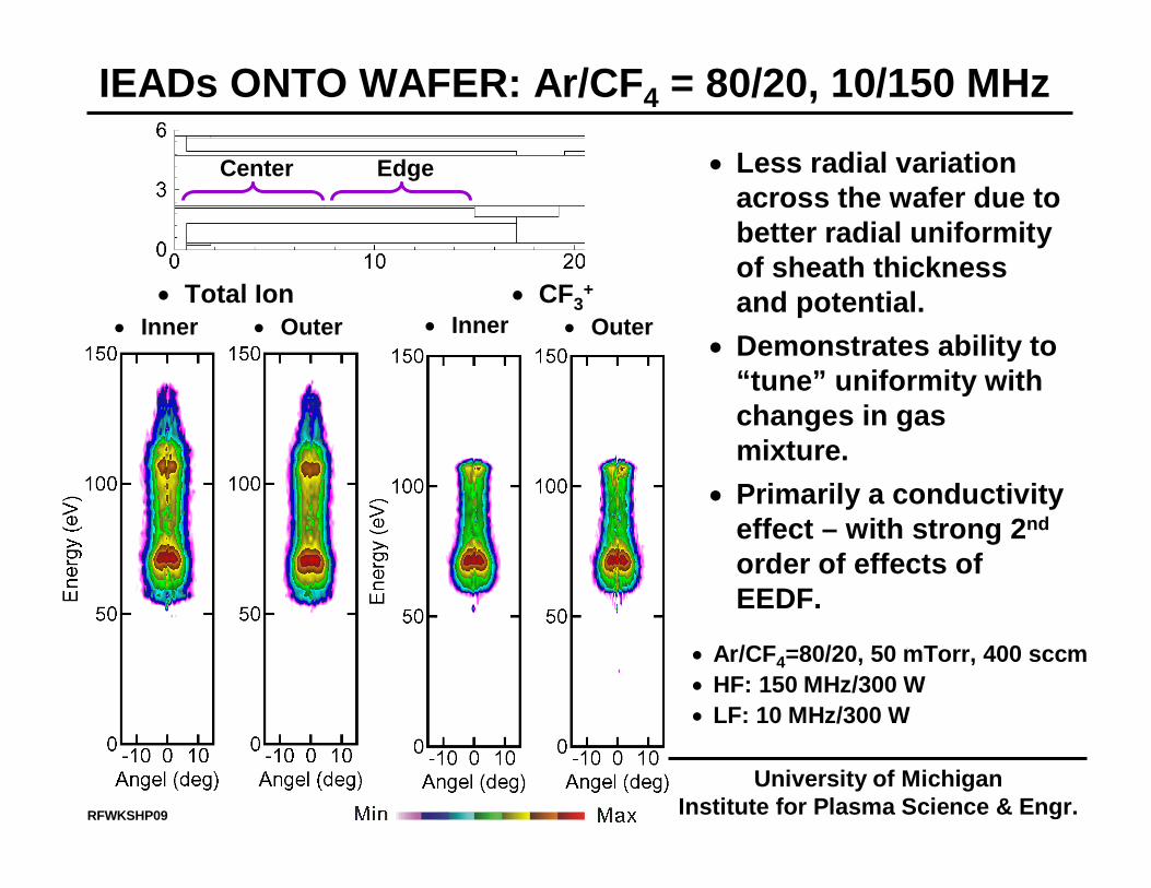
IEADs ONTO WAFER: Ar/CF4 = 80/20, 10/150 MHz
RFWKSHP09
• Total Ion • CF3+
• Inner • Inner• Outer • Outer
• Less radial variation across the wafer due to better radial uniformity of sheath thickness and potential.
• Demonstrates ability to “tune” uniformity with changes in gas mixture.
• Primarily a conductivity effect – with strong 2nd
order of effects of EEDF.
• Ar/CF4=80/20, 50 mTorr, 400 sccm• HF: 150 MHz/300 W• LF: 10 MHz/300 W
University of MichiganInstitute for Plasma Science & Engr.
RFWKSHP09
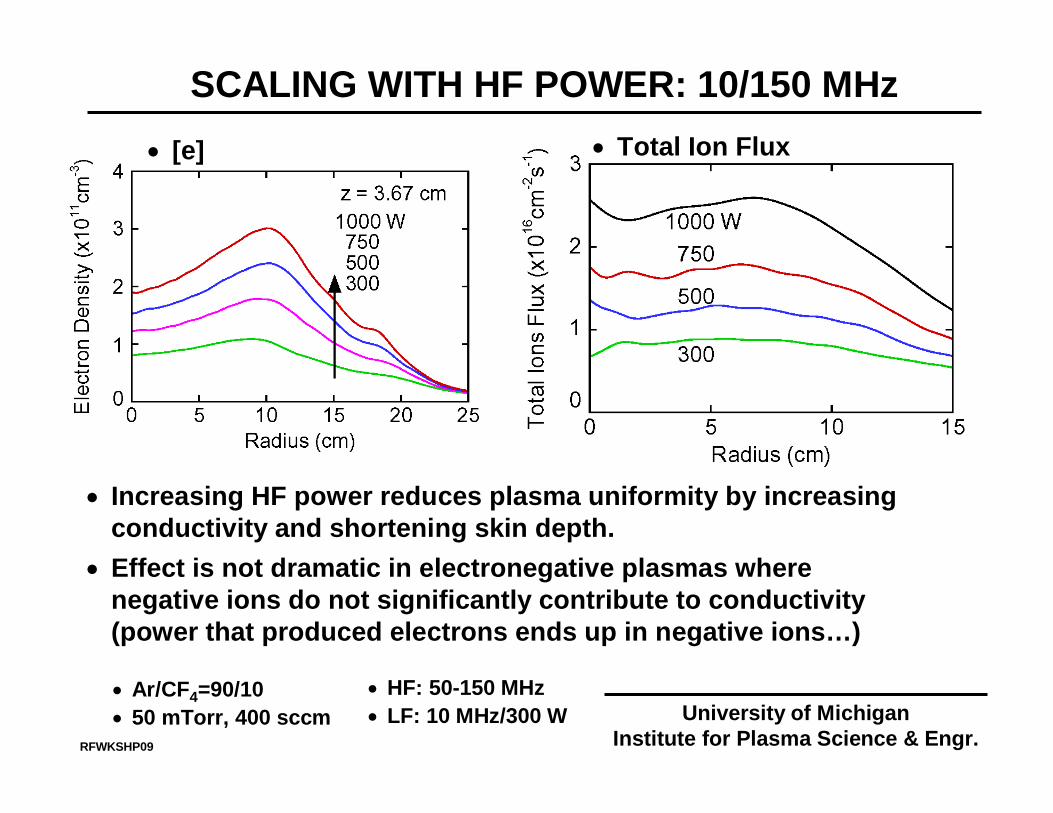
• Increasing HF power reduces plasma uniformity by increasing conductivity and shortening skin depth.
• Effect is not dramatic in electronegative plasmas where negative ions do not significantly contribute to conductivity (power that produced electrons ends up in negative ions…)
• Ar/CF4=90/10• 50 mTorr, 400 sccm
• HF: 50-150 MHz• LF: 10 MHz/300 W
• Total Ion Flux
University of MichiganInstitute for Plasma Science & Engr.
SCALING WITH HF POWER: 10/150 MHz• [e]
Center Edge
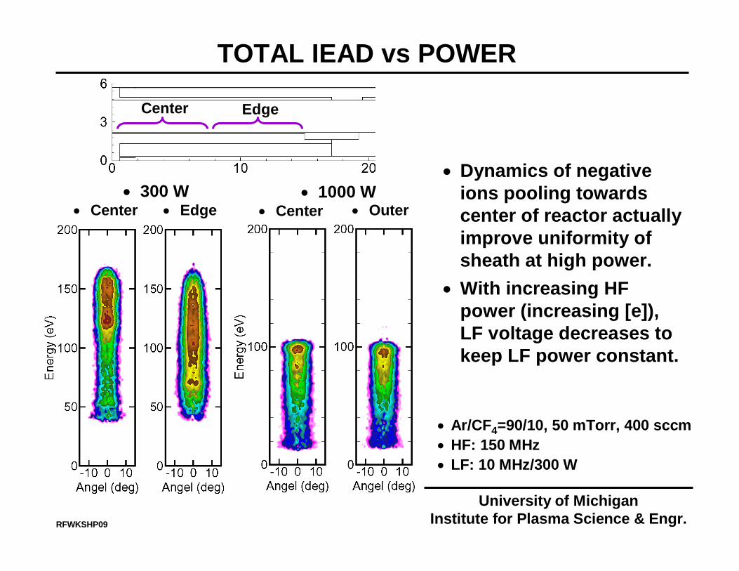
TOTAL IEAD vs POWER
RFWKSHP09
• 300 W• Center • Center• Edge • Outer
• Dynamics of negative ions pooling towards center of reactor actually improve uniformity of sheath at high power.
• With increasing HF power (increasing [e]), LF voltage decreases to keep LF power constant.
• Ar/CF4=90/10, 50 mTorr, 400 sccm• HF: 150 MHz• LF: 10 MHz/300 W
• 1000 W
University of MichiganInstitute for Plasma Science & Engr.
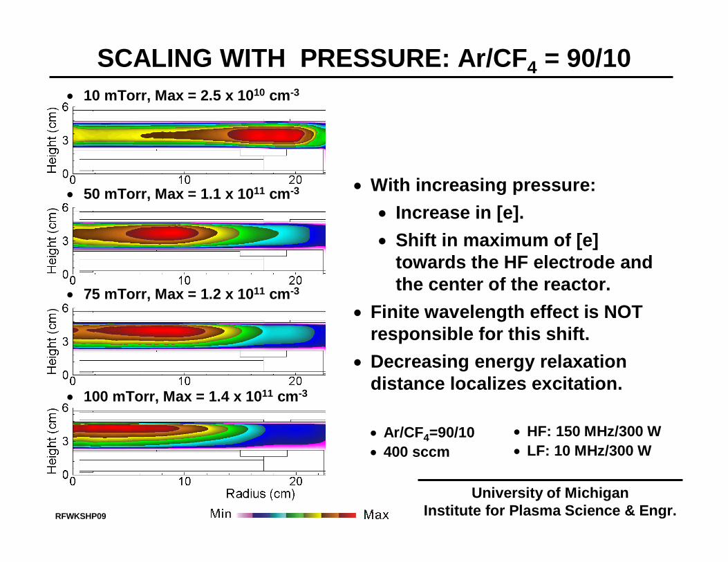
SCALING WITH PRESSURE: Ar/CF4 = 90/10• 10 mTorr, Max = 2.5 x 1010 cm-3
• 50 mTorr, Max = 1.1 x 1011 cm-3
• 75 mTorr, Max = 1.2 x 1011 cm-3
• 100 mTorr, Max = 1.4 x 1011 cm-3
• With increasing pressure:• Increase in [e].• Shift in maximum of [e]
towards the HF electrode and the center of the reactor.
• Finite wavelength effect is NOT responsible for this shift.
• Decreasing energy relaxation distance localizes excitation.
• Ar/CF4=90/10• 400 sccm
• HF: 150 MHz/300 W• LF: 10 MHz/300 W
University of MichiganInstitute for Plasma Science & Engr.RFWKSHP09
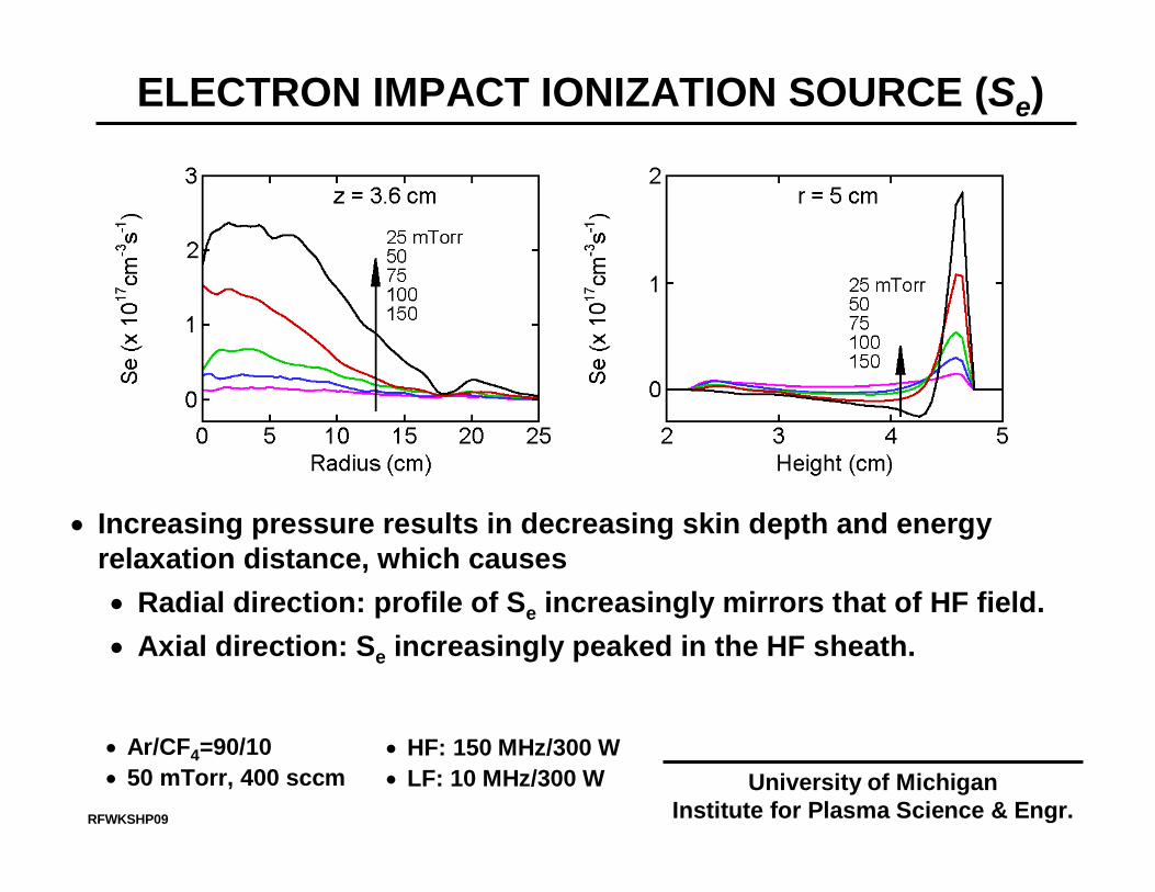
ELECTRON IMPACT IONIZATION SOURCE (Se)
• Increasing pressure results in decreasing skin depth and energy relaxation distance, which causes• Radial direction: profile of Se increasingly mirrors that of HF field.• Axial direction: Se increasingly peaked in the HF sheath.
• Ar/CF4=90/10• 50 mTorr, 400 sccm
• HF: 150 MHz/300 W• LF: 10 MHz/300 W University of Michigan
Institute for Plasma Science & Engr.RFWKSHP09
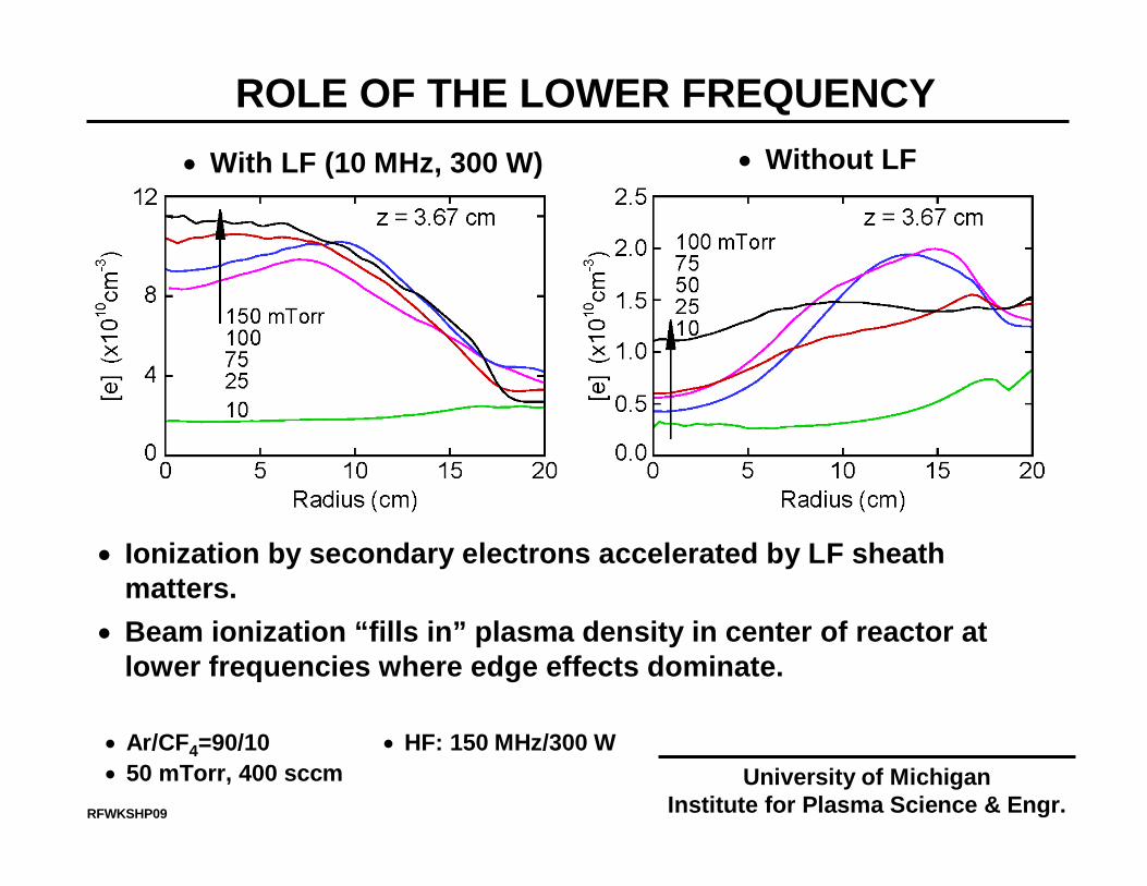
ROLE OF THE LOWER FREQUENCY
• Ar/CF4=90/10• 50 mTorr, 400 sccm
• Ionization by secondary electrons accelerated by LF sheath matters.
• Beam ionization “fills in” plasma density in center of reactor at lower frequencies where edge effects dominate.
• Without LF• With LF (10 MHz, 300 W)
• HF: 150 MHz/300 WUniversity of Michigan
Institute for Plasma Science & Engr.RFWKSHP09

WHAT ABOUT 450 mm and 16 nm?
RFWKSHP09
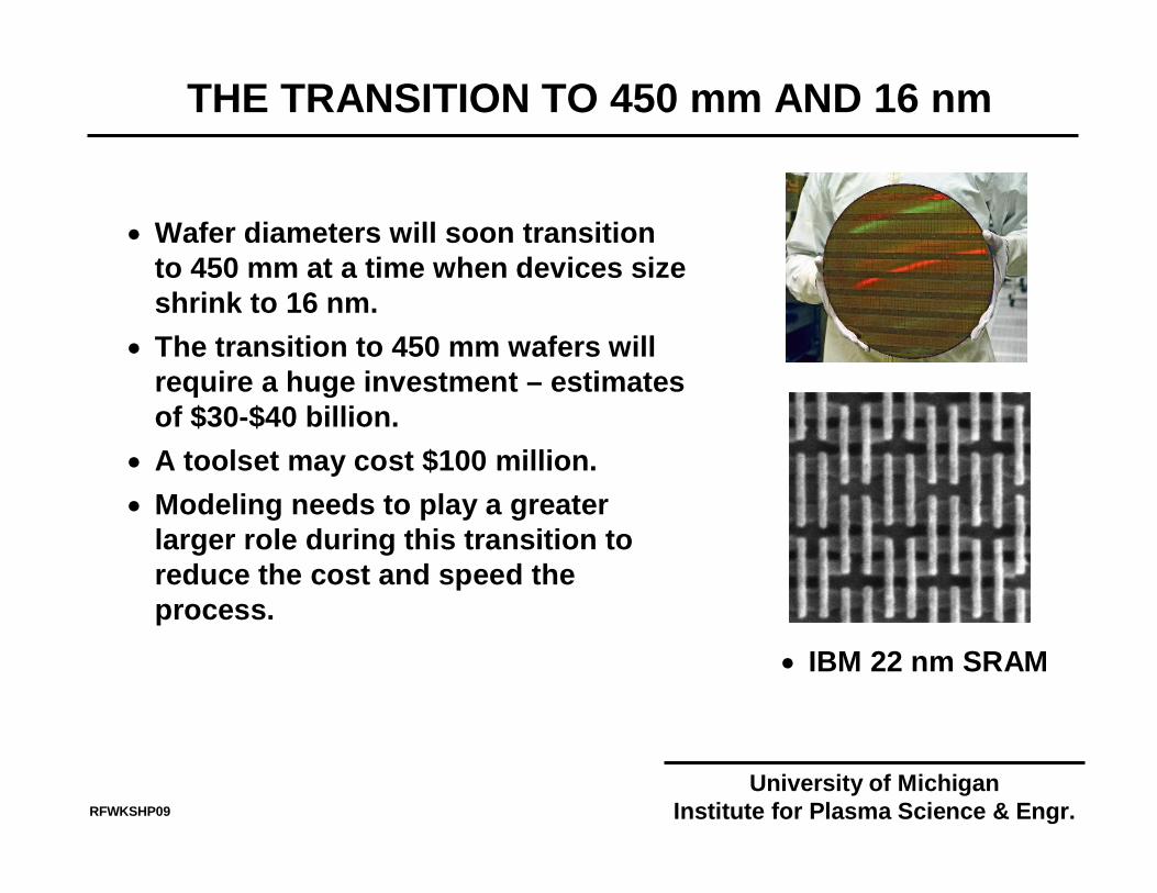
THE TRANSITION TO 450 mm AND 16 nm
RFWKSHP09
• Wafer diameters will soon transition to 450 mm at a time when devices size shrink to 16 nm.
• The transition to 450 mm wafers will require a huge investment – estimates of $30-$40 billion.
• A toolset may cost $100 million.• Modeling needs to play a greater
larger role during this transition to reduce the cost and speed the process.
• IBM 22 nm SRAM
University of MichiganInstitute for Plasma Science & Engr.
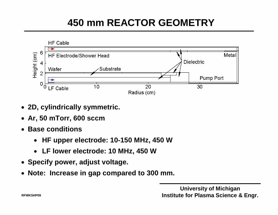
450 mm REACTOR GEOMETRY
• 2D, cylindrically symmetric.• Ar, 50 mTorr, 600 sccm • Base conditions
• HF upper electrode: 10-150 MHz, 450 W• LF lower electrode: 10 MHz, 450 W
• Specify power, adjust voltage.• Note: Increase in gap compared to 300 mm.
University of MichiganInstitute for Plasma Science & Engr.RFWKSHP09
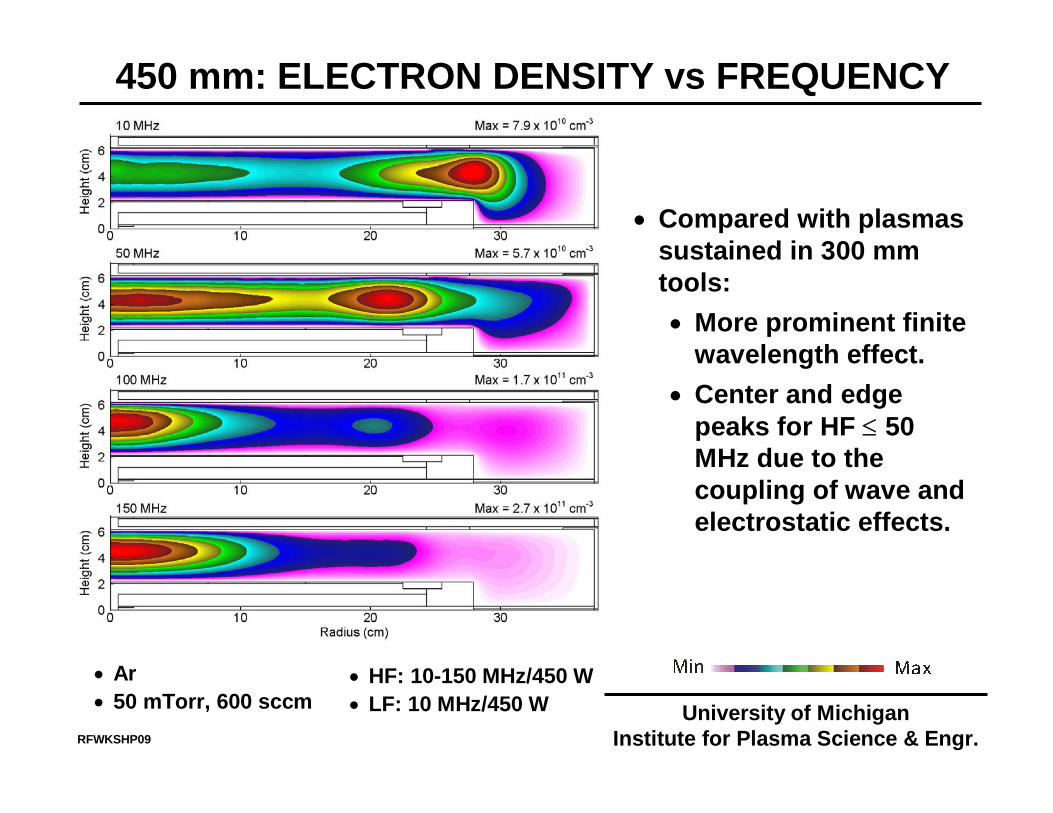
450 mm: ELECTRON DENSITY vs FREQUENCY
• Compared with plasmas sustained in 300 mm tools:• More prominent finite
wavelength effect.• Center and edge
peaks for HF ≤ 50 MHz due to the coupling of wave and electrostatic effects.
• Ar• 50 mTorr, 600 sccm
• HF: 10-150 MHz/450 W• LF: 10 MHz/450 W University of Michigan
Institute for Plasma Science & Engr.RFWKSHP09
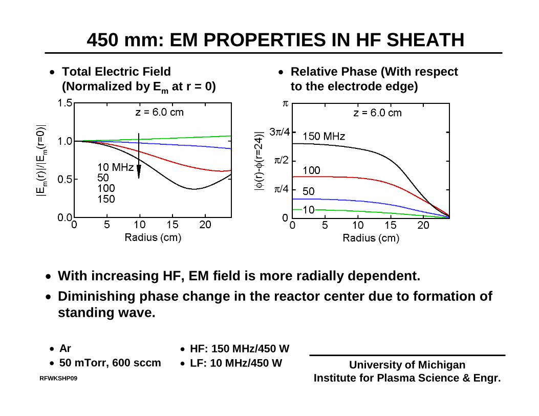
450 mm: EM PROPERTIES IN HF SHEATH
• With increasing HF, EM field is more radially dependent.• Diminishing phase change in the reactor center due to formation of
standing wave.
• Total Electric Field (Normalized by Em at r = 0)
• Relative Phase (With respect to the electrode edge)
• Ar• 50 mTorr, 600 sccm
• HF: 150 MHz/450 W• LF: 10 MHz/450 W University of Michigan
Institute for Plasma Science & Engr.RFWKSHP09
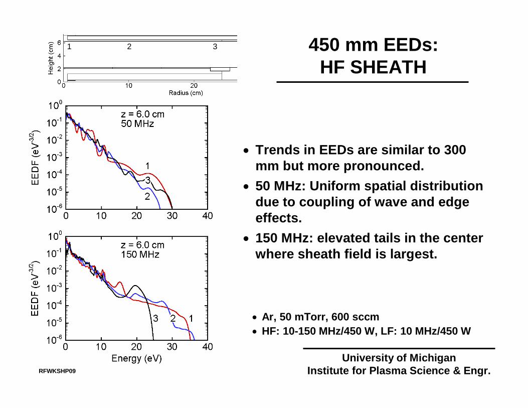
450 mm EEDs:HF SHEATH
• Ar, 50 mTorr, 600 sccm• HF: 10-150 MHz/450 W, LF: 10 MHz/450 W
• Trends in EEDs are similar to 300 mm but more pronounced.
• 50 MHz: Uniform spatial distribution due to coupling of wave and edge effects.
• 150 MHz: elevated tails in the center where sheath field is largest.
University of MichiganInstitute for Plasma Science & Engr.
1 2 3
RFWKSHP09
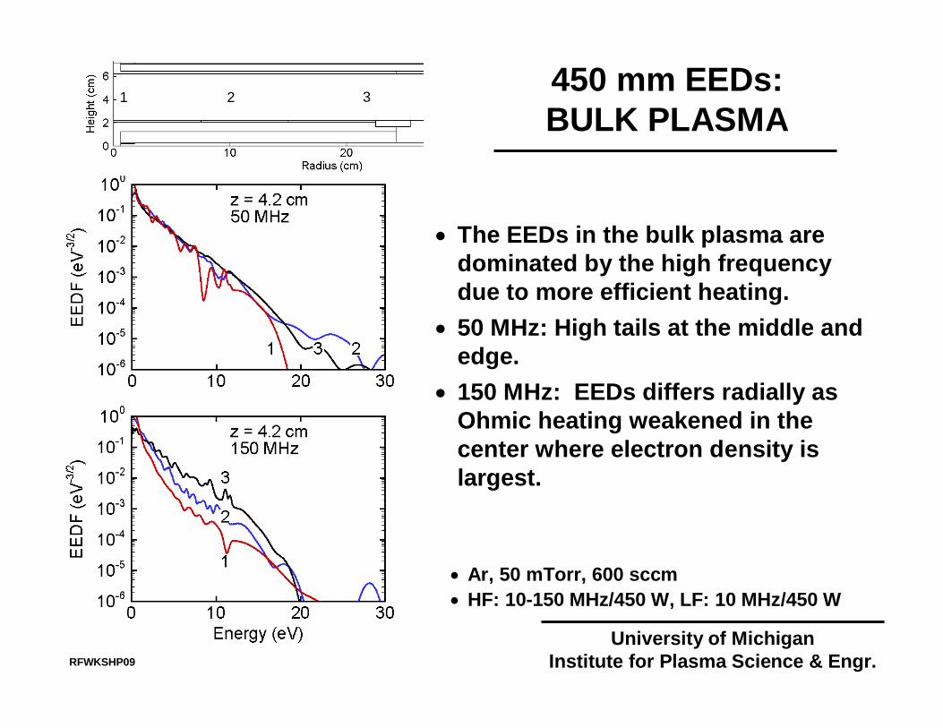
• The EEDs in the bulk plasma are dominated by the high frequency due to more efficient heating.
• 50 MHz: High tails at the middle and edge.
• 150 MHz: EEDs differs radially as Ohmic heating weakened in the center where electron density is largest.
University of MichiganInstitute for Plasma Science & Engr.
1 2 3
• Ar, 50 mTorr, 600 sccm• HF: 10-150 MHz/450 W, LF: 10 MHz/450 W
450 mm EEDs:BULK PLASMA
RFWKSHP09
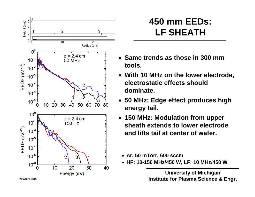
• Same trends as those in 300 mm tools.
• With 10 MHz on the lower electrode, electrostatic effects should dominate.
• 50 MHz: Edge effect produces high energy tail.
• 150 MHz: Modulation from upper sheath extends to lower electrode and lifts tail at center of wafer.
University of MichiganInstitute for Plasma Science & Engr.
1 2 3
• Ar, 50 mTorr, 600 sccm• HF: 10-150 MHz/450 W, LF: 10 MHz/450 W
450 mm EEDs:LF SHEATH
RFWKSHP09
ELECTRON IMPACT IONIZATION SOURCES
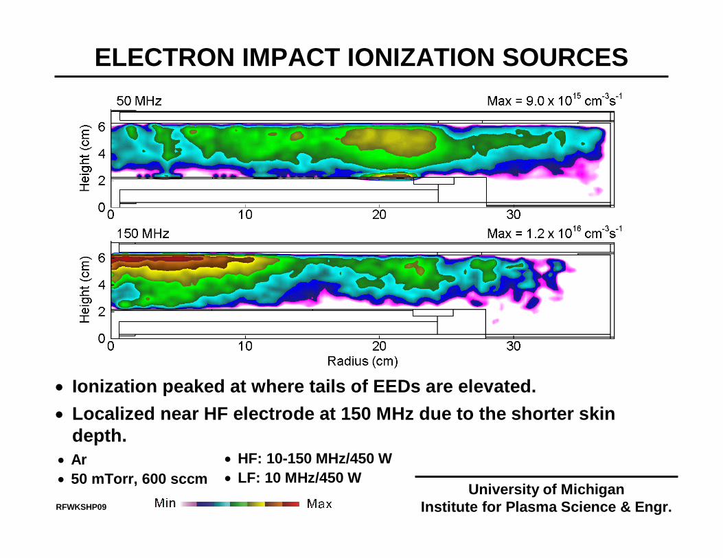
• Ionization peaked at where tails of EEDs are elevated.• Localized near HF electrode at 150 MHz due to the shorter skin
depth.• Ar• 50 mTorr, 600 sccm
• HF: 10-150 MHz/450 W• LF: 10 MHz/450 W
University of MichiganInstitute for Plasma Science & Engr.RFWKSHP09
ION FLUX AND IEADs INCIDENT ON WAFER
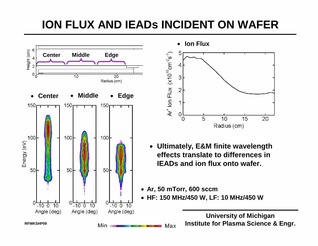
• Center • Edge
• Ion Flux
• Middle
Center Middle Edge
• Ar, 50 mTorr, 600 sccm• HF: 150 MHz/450 W, LF: 10 MHz/450 W
• Ultimately, E&M finite wavelength effects translate to differences in IEADs and ion flux onto wafer.
University of MichiganInstitute for Plasma Science & Engr.RFWKSHP09

CAN WE INNOVATE AROUND THE PHYSICS?
• For uniform processing at 450 mm, the electrical distance from rf feed-to-plasma must be equal.
• Segmented electrodes are used in large area plasma processing for LCD panels and solar cells.
• Has their day come for microelectronics?
• Let modeling answer that question…
RFWKSHP09
• The model….segmented electrodes.
University of MichiganInstitute for Plasma Science & Engr.
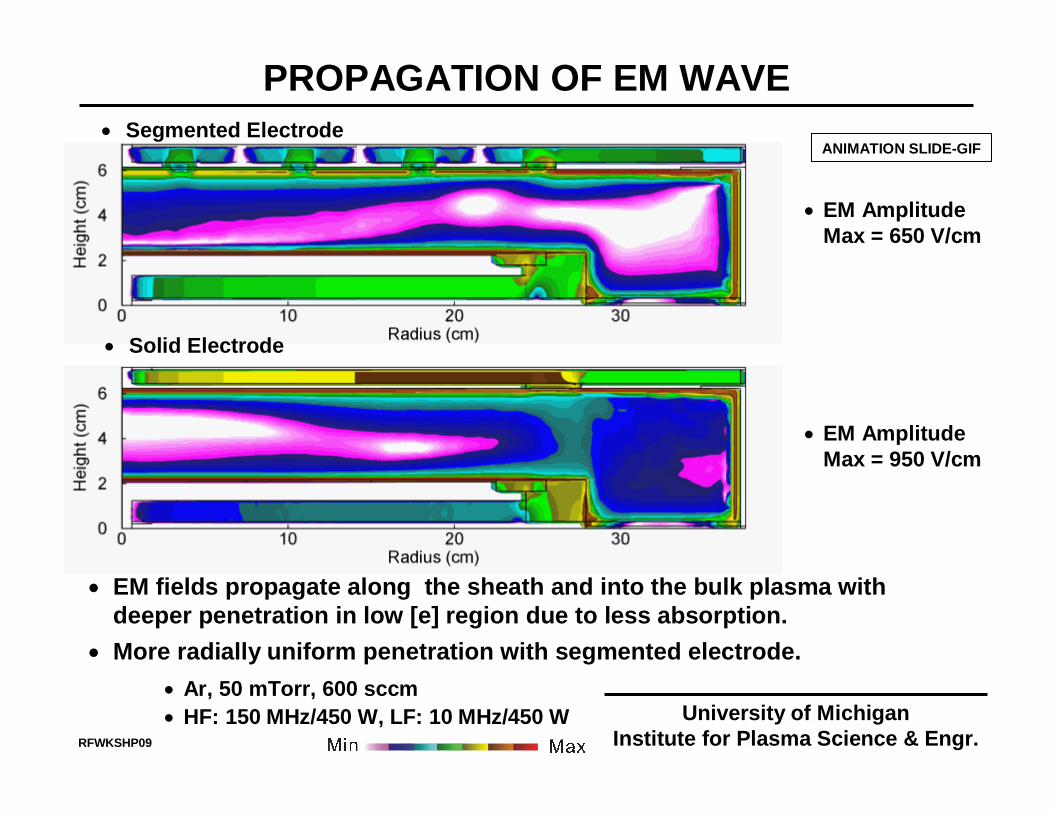
PROPAGATION OF EM WAVE
• EM fields propagate along the sheath and into the bulk plasma with deeper penetration in low [e] region due to less absorption.
• More radially uniform penetration with segmented electrode.• Ar, 50 mTorr, 600 sccm• HF: 150 MHz/450 W, LF: 10 MHz/450 W
ANIMATION SLIDE-GIF
• EM AmplitudeMax = 650 V/cm
• Segmented Electrode
• Solid Electrode
• EM AmplitudeMax = 950 V/cm
University of MichiganInstitute for Plasma Science & Engr.RFWKSHP09
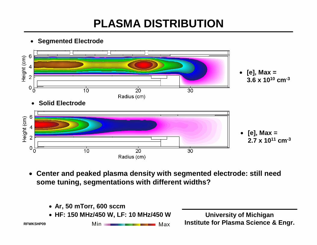
PLASMA DISTRIBUTION
• Center and peaked plasma density with segmented electrode: still need some tuning, segmentations with different widths?
• Ar, 50 mTorr, 600 sccm• HF: 150 MHz/450 W, LF: 10 MHz/450 W
• [e], Max =3.6 x 1010 cm-3
• Segmented Electrode
• Solid Electrode
• [e], Max =2.7 x 1011 cm-3
University of MichiganInstitute for Plasma Science & Engr.RFWKSHP09
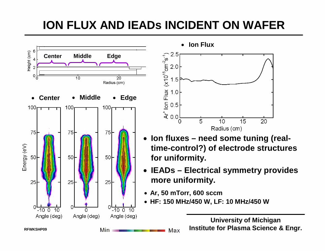
ION FLUX AND IEADs INCIDENT ON WAFER
• Center • Edge
• Ion Flux
• Ion fluxes – need some tuning (real-time-control?) of electrode structures for uniformity.
• IEADs – Electrical symmetry provides more uniformity.
• Middle
• Ar, 50 mTorr, 600 sccm• HF: 150 MHz/450 W, LF: 10 MHz/450 W
Center Middle Edge
University of MichiganInstitute for Plasma Science & Engr.RFWKSHP09
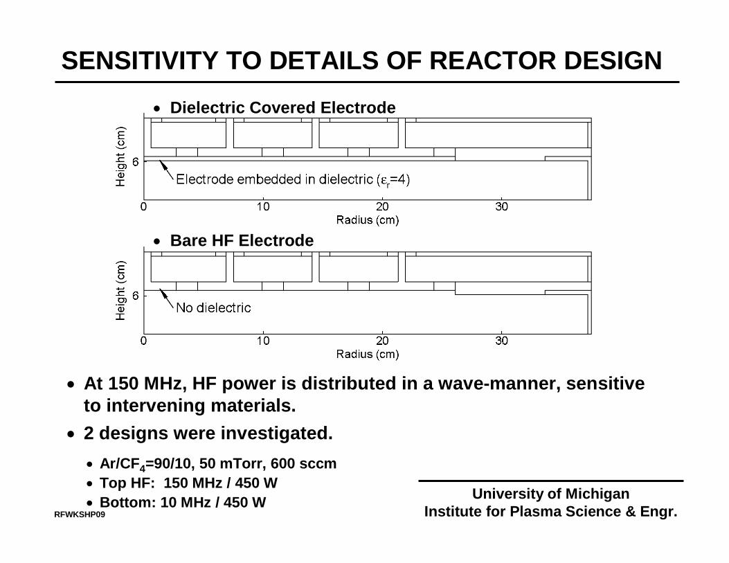
SENSITIVITY TO DETAILS OF REACTOR DESIGN
• Ar/CF4=90/10, 50 mTorr, 600 sccm• Top HF: 150 MHz / 450 W• Bottom: 10 MHz / 450 W
• At 150 MHz, HF power is distributed in a wave-manner, sensitive to intervening materials.
• 2 designs were investigated.
• Dielectric Covered Electrode
• Bare HF Electrode
University of MichiganInstitute for Plasma Science & Engr.RFWKSHP09

PLASMA DISTRIBUTION
• HF: 150 MHz/450 W• LF: 10 MHz/450 W
• Ar/CF4=90/10• 50 mTorr, 600 sccm
• Dielectric Covered
• Bare HF Electrode
• Subtleties of propagation and interaction of EM fields produce differences in the plasma distributions.
• With bare HF electrode, [e] is more uniform over the inner 2/3 of the wafer.
University of MichiganInstitute for Plasma Science & Engr.RFWKSHP09
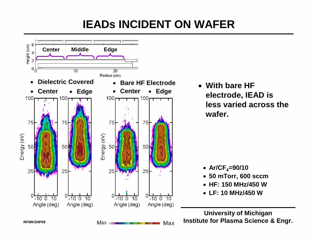
Center Middle Edge
IEADs INCIDENT ON WAFER
• Center • Edge• With bare HF
electrode, IEAD is less varied across the wafer.
• Center • Edge• Dielectric Covered • Bare HF Electrode
• Ar/CF4=90/10• 50 mTorr, 600 sccm• HF: 150 MHz/450 W• LF: 10 MHz/450 W
University of MichiganInstitute for Plasma Science & Engr.RFWKSHP09
CONCLUDING REMARKS
• Scaling of dual-frequencies CCPs has been numerically investigated for HF up to 150 MHz.
• Finite wavelength effects…not a simple scaling exercise.• Ultimately, a function of conductivity with a strong 2nd order
effect of feedback of EEDs on ionization sources.• Gas mixtures, pressures are strong 1st order effects in both
conductivity and EEDs.• Issues become only more pronounced at 450 mm. • It is unclear that conventional CCP designs (at high frequency)
will serve well at 450 mm.• Perhaps segmented electrodes will see their day.
University of MichiganInstitute for Plasma Science & Engr.RFWKSHP09


![[Center for chemical_process_safety_(ccps)]_layer_(book_fi.org)](https://img.pdfslide.us/doc/110x75/587a626d1a28ab8a2a8b47af/center-for-chemicalprocesssafetyccpslayerbookfiorg.jpg)


![CCPS Metric Pres Customizable[1]](https://img.pdfslide.us/doc/110x75/577cc37b1a28aba711961ae1/ccps-metric-pres-customizable1.jpg)