Embed Size (px)
Citation preview
IJSRSET3406 | NCRISE | March-April-2017 [(3) 4: 26-37]
National Conference on Recent Innovations in Science And Engineering (NCRISE)
International Journal of Scientific Research in Science, Engineering and Technology
© 2017 IJSRSET | Volume 3 | Issue 4
26
Lanthanum Phosphate Based Ceramic Composite Coatings for High Emissivity Applications
Aniantony1, Ananthakumar Solaiappan2 *1
Department of Materials Science and Technology, NIT Calicut, Kerala, India 2Department of Materials science and technology, NIEST-CSIR, Trivandrum, , India
ABSTRACT
Lanthanum phosphate, a soft ceramic material, with low thermal conductivity, high melting point and high
temperature phase stability is a good candidate for getting a tough ceramic coating for use at high temperatures. In
this work, a novel high emissivity ceramic coating based on lanthanum phosphate ceramic pigment was developed.
Initially, a black pigment based on lanthanum phosphate with an L* value of 34.71 was obtained through solid state
reaction by suitable pigment addition and subsequent high temperature firing. This pigment was then brush painted
on to alumina and stainless steel substrates using aluminium phosphate and sodium silicate inorganic binders and
fired at suitable temperatures for setting of coatings. The average spectral emissivities of the coatings in the
wavelength range 0.7μm to 2.5μm was above 0.9. The emissivity variation with porosity of substrate, temperature,
roughness of coating and viscosity of binders was studied for getting an optimised coating with high emissivity.
Keywords: Lanthanum Phosphate, Thermal Conductivity, Aluminium Phosphate, Orthophosphoric Acid, LaPO4,
NH3, Aluminum and Alumina
I. INTRODUCTION
A ceramic is an inorganic, nonmetallic solid material
comprising metal and a nonmetal atoms held by ionic
or covalent bonds [1]. They can be mainly classified
into amorphous, semi crystalline and crystalline
ceramics. High melting temperature, high hardness,
poor conductivity, high moduli of elasticity, chemical
resistance and low ductility are some of the common
properties of ceramics with known exceptions to each of
these rules (e.g. piezoelectric ceramics, glass transition
temperature, superconductive ceramics, etc.). The word
ceramics is derived from greek word keramikos
meaning pottery and the earliest ceramics made by
humans were pottery objects made from clay, either by
itself or mixed with other materials like silica, hardened,
sintered, in fire [2]. Later these ceramics were glazed
and fired to create smooth andcolored surfaces,
decreasing porosity through the use of glassy,
amorphous ceramic coatings on top of the crystalline
ceramic substrates. Ceramics fiinds a number of
applications in domestic, industrial and building
products, as well as in a wide range of ceramic art. New
ceramic materials were developed for use in advanced
ceramic engineering, such as in semiconductors in the
20th century.
II. METHODS AND MATERIAL
Lanthanum phosphate is obtained by sol-gel method by
the addition of orthophosphoric acid (H3PO4, 85%,
Merck Specialties Private Limited, India) to lanthanum
nitrate hexahydrate salt (La(NO3)3.6H2O, 99.99%, Alfa
Aesar). A solution of La (NO3)3.6H2O is made in
distilled water. The amount of La (NO3)3.6H2O and
distilled water required for the solution is calculated on
the basis of the amount of LaPO4 required. The solution
is stirred thoroughly using a mechanical stirrer for 30
minutes.
Orthophosphoric acid solution in distilled water is
added drop by drop to the stirring solution. The solution
is allowed to stir for about 30 minutes after the complete
addition of orthophosphoric acid. The pH of the solution
is checked using litmus paper. Now add a small amount
of NH3 drop by drop to convert the pH to 7. This
Volume 3 | Issue 4 | 2017 | www.ijsrset.com 27
conversion from acidic pH to basic aids the precipitation
of LaPO4 and allowed to precipitate completely. The
LaPO4 precipitate is filtered thoroughly using filter
paper and Buckner funnel. The precipitate thus obtained
is washed 5 to 10 times thoroughly with hot distilled
water to remove the NH3 content. The obtained
precipitate is dried in a water bath arrangement. The
dried LaPO4 flakes obtained are crushed into powder
using mortar and pestle. The process chart for LaPO4
preparation is given in figure 3.1.
Figure 3.1 Process flow chart for LaPO4 preparation.
III. Synthesis of LaPO4 Based Pigments And
Compacts
Solid State Reaction method as dicussed below was used for
pigment and compact preparation. For pigment and compacts
production initially lanthanum phosphate prepared from the
above route discussed was taken and mixed with powders
available in the laboratory such as NiO, Co2O3, Co3O4, MnO2,
CuO etc. with a specific weight ratio. This composite mixture
was then taken for wet ball milling using Zirconia balls
having a weight of 3g each. The weight of powder to balls
was chosen to be 1:3 for proper milling. Water-Propan-2-ol
mixture with 1:1 volume ratio was taken as the ball milling
medium. Ball milling was done in a 350ml milling plastic
bottle. For 15g of powder mixture about 250 ml of (water-
propan-2-ol) was taken. It was then ball milled for 24 hours
at an rpm of 300. Such long time of ball milling allows for
proper and uniform mixing and size reduction of powders.
The resulting mixture was then heated in a hot plate till all
water and propan-2-ol gets evaporated. For NIR reflective
pigments this precursor powder was heat treated at 12000C in
a high temperature furnace. For obtaining black pigments and
black ceramic compacts, the precursor powder was calcined
at 6000Cfor 2 hours in an alumina crucible. For obtaining
black pigments, calcined powders was heat treated at 12000C
for 2 hours in an alumina crucible and for obtaining ceramic
compacts, the calcined powders were compacted in a press
under a pressure of 1 Ton with a holding time of 1 minute and
then sintered in air atmosphere at 14000C for 1 hour in a high
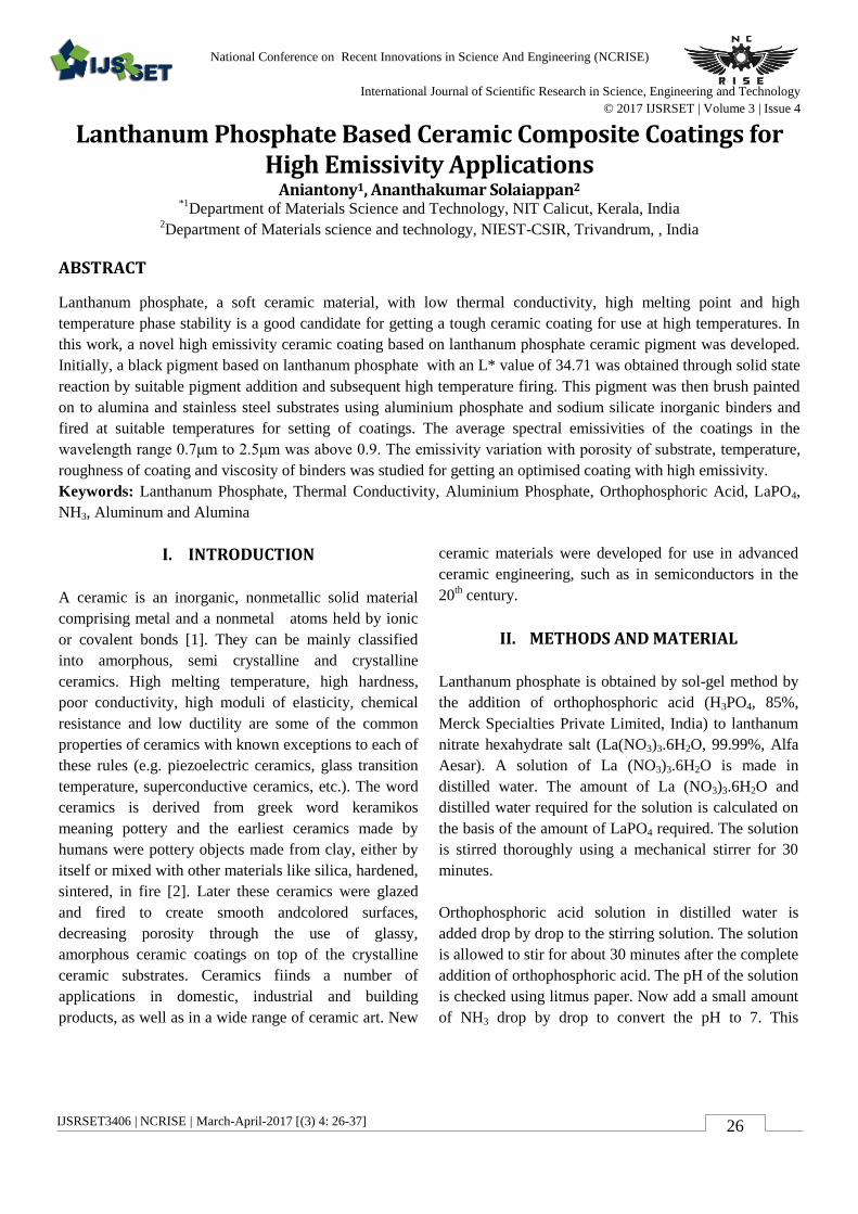
temperature furnace. Figures of some of the equiments and
it’s make used in pigment and compact production are given
in fig 3.1
Fig 3.2 Hydraulic Press Ball Mill Unit
(make:Carver)
3.1 Synthesis of Binders And Coatings
Since organic binders do not have high temperature stability,
inorganic binders where chosen. Coatings were prepared with
two different inorganic binders.One was an alkali metal
silicate binder (Sodium-Silicate) with SiO2:Na2O in the ratio
2:1. They are used for making heat resistant paints. Other was
an acidic aluminium phosphate binder [38]. Acid aluminum
phosphate refers to a liquid solution of phosphoric acid
(H3PO4) and an aluminum salt (e.g., aluminum hydroxide),
such that the proportion of acid is above that needed to form
solid aluminum phosphate (e.g., Al(PO3)3, which is aluminum
metaphosphate, and AlPO4, which is aluminum
orthophosphate). Hence the P/Al molar ratio in acid
aluminum phosphate is typically much higher than 3.
Elements other than aluminum (e.g., calcium) can be used in
acid phosphates, but aluminum is most commonly used, due
to the wide availability of aluminum salts and the importance
of aluminum and alumina (Al2O3) among engineering
materials. Phosphoric acid itself can be used for the binding
and surface modification of materials (e.g., ceramics), but the
addition of aluminum significantly enhances the bonding
ability. Heat treatment is needed subsequent to application of
the acid aluminum phosphate in binding or coating.
The heat treatment is partly for the purpose of drying and
results in the formation of crystalline and amorphous
aluminum phosphate solid phases, depending on the heating
temperature and the possible interaction or reaction between
the acid phosphate and the material to be bound or coated.
Aluminum metaphosphate is a crystalline phase that is
commonly formed after heating at 500–800◦C.
For coatings, a pigment to binder weight ratio of 1:1.3 was
chosen. Usually applications such as for spray painting, brush
painting etc, the pigment to binder weight ratio is varied
between 1:1 to 1:1.5. A smaller ratio below this region leads
Volume 3 | Issue 4 | 2017 | www.ijsrset.com 28
to increased viscosity and painting or brushing may be very
difficult, while a higher ratio above this region may degrade
or affect the advantageous properties of the ceramic powders
added. Hence an optimum ratio of 1.:1.3 within the allowed
variation was chosen.As already discussed, every high
emissivity coating will comprise of a refractory pigment, high
emissivity agents and a suitable binder. With this regard, from
the pigments synthesized from the above step, a black
pigment was taken and coated with two different binders on
to alumina and stainless steel 304 substrates. Samples coated
with sodium-silicate binder was dried at 2000C and samples
coated with aluminium phosphate was dried at 5000C in a low
temperature furnace for 2 hours.
IV. RESULTS AND DISCUSSION
In this part, the results of the experiments conducted and
discussions on that results based on the observations are done.
The results obtained for pigments, binders, coatings and
ceramic compacts in that order is studied and discussed. NIR
reflective pigments for cool roof appication and black
pigments for high emissivity applications were produced and
characterized separately as discussed below.
4.1 Near Infrared Reflecting Pigments
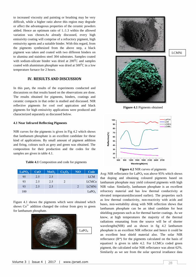
NIR curves for the pigments is given in Fig 4.2 which shows
that lanthanum phosphate is an excellent candidate for these
kind of applications. By small amount of pigment addition
and firing, colours such as grey and green was obtained. The
composition for their production and the codes for the
samples are given in table 4.1.
Table 4.1 Composition and code for pigments
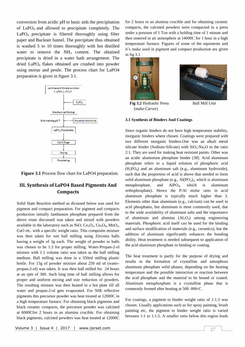
Figure 4.1 shows the pigments which were obtained which
shows Co3+
addition changed the colour from grey to green
for lanthanum phosphate.
Figure 4.1 Pigments obtained
Figure 4.2 NIR curves of pigments
Avg: NIR reflectance for LaPO4 was above 95% which shows
that doping and obtaining coloured pigments based on
lanthanum phosphate may yield coloured pigments with high
NIR value. Similarily, lanthanum phosphate is an excellent
refractory material and has low thermal conductivity at
elevated temperature(discussed earlier). The properties such
as low thermal conductivity, non-reactivity with acids and
bases, non-wettability along with NIR reflection shows that
lanthanum phosphate can be an ideal candidate for heat
shielding purposes such as for thermal barrier coatings. As we
know, at high temperatures the majority of the thermal
radiations emanating from the source will be of shorter
wavelengths(NIR) and as shown in fig 4.2 lanthanum
phosphate is an excellent NIR reflector and hence it could be
an excellent heat shield material also. The solar NIR
reflectance (R*) for the pigments calculated on the basis of
equation1 is given in table 4.2. For LCMCo coded green
pigment, the calculated solar NIR reflectance was about 62%.
Similarily as we see from the solar spectral irradiance data
LaPO4
LCMNi
LCMCo
Volume 3 | Issue 4 | 2017 | www.ijsrset.com 29
(figure 1.6), most of the energy of the solar radiation in the
NIR part is concentrated in the region from 700 to 1100 nm.
As we see from the NIR curve of LCMCo green pigment, the
reflectance in the above said region is high, hence it will be
an ideal cool pigment. The other two pigments were grey in
colour with LCM pigment having an R* value of 32%. R*
values of some commercial pigments and of some pigments
taken from literature with their colour in bracket is given in
table 4.3.
Table 4.2 Solar NIR reflectance (R*) of pigments
Table 4.3 NIR Solar reflectance of some pigments from
literature
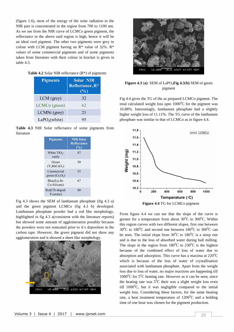
Fig 4.3 shows the SEM of lanthanum phosphate (fig 4.3 a)
and the green pigment LCMCo (fig 4.3 b) developed.
Lanthanum phosphate powder had a rod like morphology,
highlighted in fig 4.3 a(consistent with the literature reports)
but showed some amount of agglomeration possibly because
the powders were not sonicated prior to it’s deposition in the
carbon tape. However, the green pigment did not show any
agglomeration and it showed a sheet like morphology.
Figure 4.3 (a) SEM of LaPO4Fig 4.3(b) SEM of green
pigment
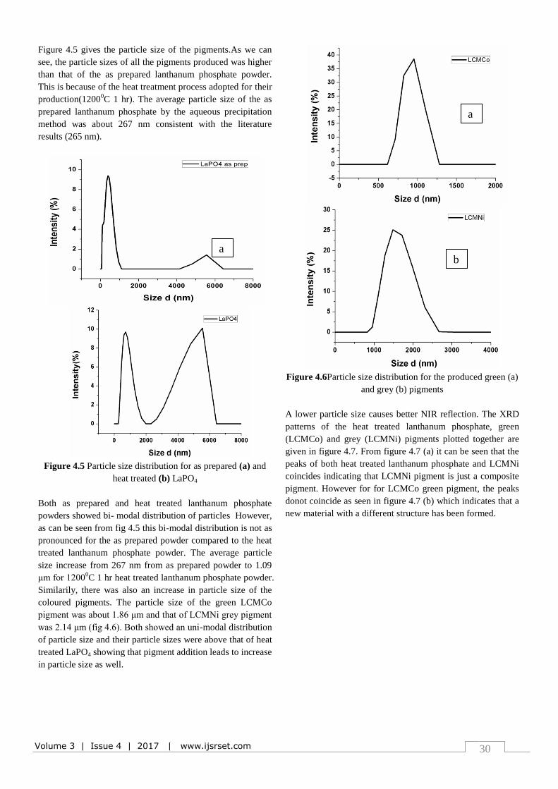
Fig 4.4 gives the TG of the as prepared LCMCo pigment. The
total calculated weight loss upto 10000C for the pigment was
10.88%. Interestingly, lanthanum phosphate had a slightly
higher weight loss of 11.11%. The TG curve of the lanthanum
phosphate was similar to that of LCMCo as in figure 4.4.
Figure 4.4 TG for LCMCo pigment
From figure 4.4 we can see that the slope of the curve is
greater for a temperature from about 300C to 300
0C. Within
this region curves with two different slopes, first one between
300C to 180
0C and second one between 180
0C to 300
0C can
be seen. The initial slope from 300C to 180
0C is a steep one
and is due to the loss of absorbed water during ball milling.
The slope in the region from 1800C to 230
0C is the highest
because of the combined effect of loss of water due to
absorption and adsorption. This curve has a maxima at 2200C
which is because of the loss of water of crystallisation
associated with lanthanum phosphate. Apart from the weight
loss due to loss of water, no major reactions are happening till
10000C for 5
0C heating rate. However as it can be seen, since
the heating rate was 50C their was a slight weight loss even
till 10000C, but it was negligible compared to the initial
weight loss. Considering these factors, for the same heating
rate, a heat treatment temperature of 12000C and a holding
time of one hour was chosen for the pigment production.
Volume 3 | Issue 4 | 2017 | www.ijsrset.com 30
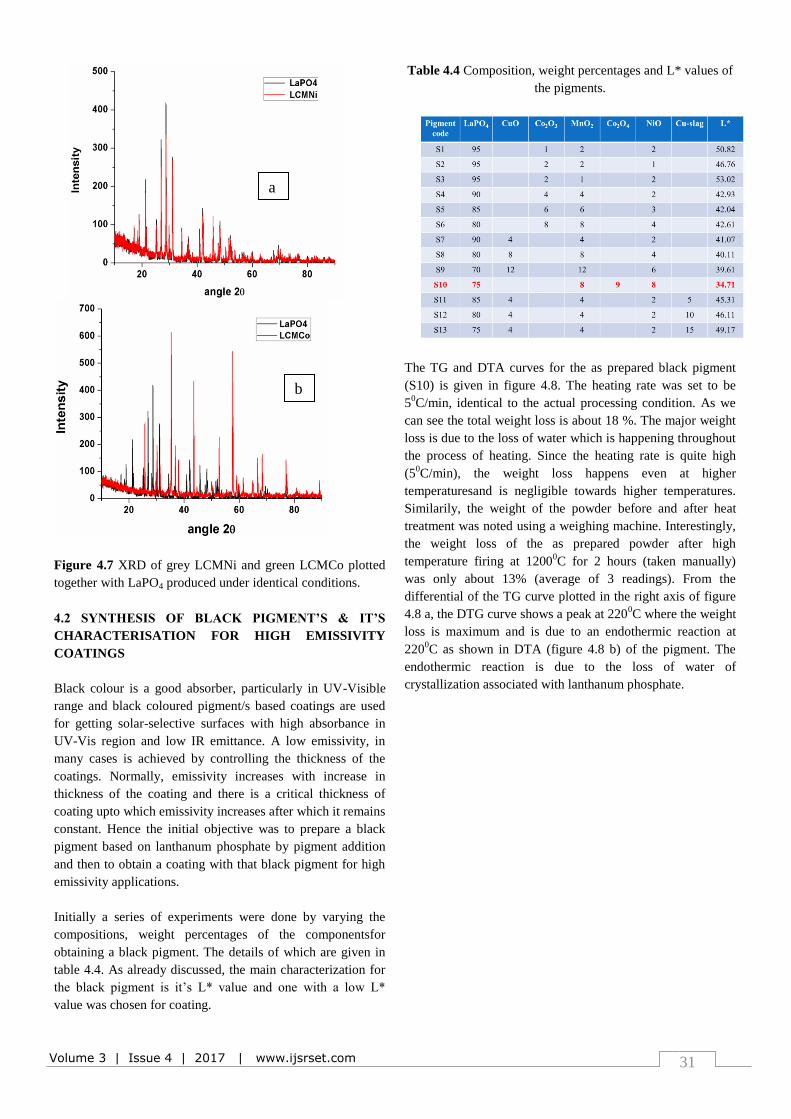
Figure 4.5 gives the particle size of the pigments.As we can
see, the particle sizes of all the pigments produced was higher
than that of the as prepared lanthanum phosphate powder.
This is because of the heat treatment process adopted for their
production(12000C 1 hr). The average particle size of the as
prepared lanthanum phosphate by the aqueous precipitation
method was about 267 nm consistent with the literature
results (265 nm).
Figure 4.5 Particle size distribution for as prepared (a) and
heat treated (b) LaPO4
Both as prepared and heat treated lanthanum phosphate
powders showed bi- modal distribution of particles However,
as can be seen from fig 4.5 this bi-modal distribution is not as
pronounced for the as prepared powder compared to the heat
treated lanthanum phosphate powder. The average particle
size increase from 267 nm from as prepared powder to 1.09
μm for 12000C 1 hr heat treated lanthanum phosphate powder.
Similarily, there was also an increase in particle size of the
coloured pigments. The particle size of the green LCMCo
pigment was about 1.86 μm and that of LCMNi grey pigment
was 2.14 μm (fig 4.6). Both showed an uni-modal distribution
of particle size and their particle sizes were above that of heat
treated LaPO4 showing that pigment addition leads to increase
in particle size as well.
Figure 4.6Particle size distribution for the produced green (a)
and grey (b) pigments
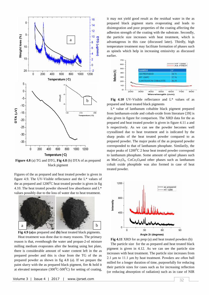
A lower particle size causes better NIR reflection. The XRD
patterns of the heat treated lanthanum phosphate, green
(LCMCo) and grey (LCMNi) pigments plotted together are
given in figure 4.7. From figure 4.7 (a) it can be seen that the
peaks of both heat treated lanthanum phosphate and LCMNi
coincides indicating that LCMNi pigment is just a composite
pigment. However for for LCMCo green pigment, the peaks
donot coincide as seen in figure 4.7 (b) which indicates that a
new material with a different structure has been formed.
a b
a
b
Volume 3 | Issue 4 | 2017 | www.ijsrset.com 31
Figure 4.7 XRD of grey LCMNi and green LCMCo plotted
together with LaPO4 produced under identical conditions.
4.2 SYNTHESIS OF BLACK PIGMENT’S & IT’S
CHARACTERISATION FOR HIGH EMISSIVITY
COATINGS
Black colour is a good absorber, particularly in UV-Visible
range and black coloured pigment/s based coatings are used
for getting solar-selective surfaces with high absorbance in
UV-Vis region and low IR emittance. A low emissivity, in
many cases is achieved by controlling the thickness of the
coatings. Normally, emissivity increases with increase in
thickness of the coating and there is a critical thickness of
coating upto which emissivity increases after which it remains
constant. Hence the initial objective was to prepare a black
pigment based on lanthanum phosphate by pigment addition
and then to obtain a coating with that black pigment for high
emissivity applications.
Initially a series of experiments were done by varying the
compositions, weight percentages of the componentsfor
obtaining a black pigment. The details of which are given in
table 4.4. As already discussed, the main characterization for
the black pigment is it’s L* value and one with a low L*
value was chosen for coating.
Table 4.4 Composition, weight percentages and L* values of
the pigments.
The TG and DTA curves for the as prepared black pigment
(S10) is given in figure 4.8. The heating rate was set to be
50C/min, identical to the actual processing condition. As we
can see the total weight loss is about 18 %. The major weight
loss is due to the loss of water which is happening throughout
the process of heating. Since the heating rate is quite high
(50C/min), the weight loss happens even at higher
temperaturesand is negligible towards higher temperatures.
Similarily, the weight of the powder before and after heat
treatment was noted using a weighing machine. Interestingly,
the weight loss of the as prepared powder after high
temperature firing at 12000C for 2 hours (taken manually)
was only about 13% (average of 3 readings). From the
differential of the TG curve plotted in the right axis of figure
4.8 a, the DTG curve shows a peak at 2200C where the weight
loss is maximum and is due to an endothermic reaction at
2200C as shown in DTA (figure 4.8 b) of the pigment. The
endothermic reaction is due to the loss of water of
crystallization associated with lanthanum phosphate.
b
a
Volume 3 | Issue 4 | 2017 | www.ijsrset.com 32
Figure 4.8 (a) TG and DTG, Fig 4.8 (b) DTA of as prepared
black pigment
Figures of the as prepared and heat treated powder is given in
figure 4.9. The UV-Visible reflectance and the L* values of
the as prepared and 12000C heat treated powder is given in fig
4.10. The heat treated powder showed low absorbance and L*
values possibly due to the loss of water due to heat treatment.
Fig 4.9 (a)as prepared and (b) heat treated black pigments.
Heat treatment was done due to many reasons. The primary
reason is that, eventhough the water and propan-2-ol mixture
milling medium evaporates after the heating using hot plate,
there is considerable amount of water content left in the as
prepared powder and this is clear from the TG of the as
prepared powder as shown in fig 4.8 (a). If we prepare the
paint slurry with the as prepared black pigment, fire & hold it
at elevated temperature (3000C-500
0C) for setting of coating,
it may not yield good result as the residual water in the as
prepared black pigment starts evaporating and leads to
disintegration and poor properties of the coating affecting the
adhesion strength of the coating with the substrate. Secondly,
the particle size increases with heat treatment, which is
advantageous in this case (discussed later). Thirdly, high
temperature treatment may facilitate formation of phases such
as spinels which help in increasing emissivity as discussed
earlier.
Fig 4.10 UV-Visible reflectance and L* values of as
prepared and heat treated black pigments
L* value of lanthanum cobaltite black pigment prepared
from lanthanum-oxide and cobalt-oxide from literature [39] is
also given in figure for comparison. The XRD data for the as
prepared and heat treated powder is given in figure 4.11 a and
b respectively. As we can see the powder becomes well
crystallined due to heat treatment and is indicated by the
sharp peaks of the heat treated powder compared to as
prepared powder. The major peaks of the as prepared powder
corresponded to that of lanthanum phosphate. Similarily, the
major peaks of 12000C 2 hour heat treated powder correspond
to lanthanum phosphate. Some amount of spinel phases such
as MnCo2O4, CoCo2O4and other phases such as lanthanum
cobalt oxide phosphide was also formed in case of heat
treated powder.
Fig 4.11 XRD for as prep (a) and heat treated powders (b)
The particle size for the as prepared and heat treated black
pigment is given in 4.12. As we can see the particle size
increases with heat treatment. The particle size increases from
2.1 μm to 11.1 μm by heat treatment. Powders are often ball
milled for a longer duration of time, purposefully for reducing
their particle sizes for cases such as for increasing reflection
(or reducing absorption of radiation) such as in case of NIR
a b
a
b
a
b
Volume 3 | Issue 4 | 2017 | www.ijsrset.com 33
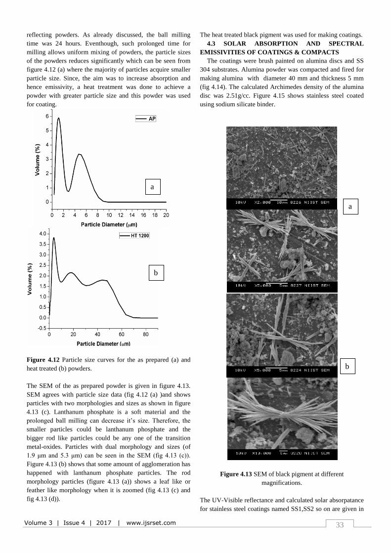
reflecting powders. As already discussed, the ball milling
time was 24 hours. Eventhough, such prolonged time for
milling allows uniform mixing of powders, the particle sizes
of the powders reduces significantly which can be seen from
figure 4.12 (a) where the majority of particles acquire smaller
particle size. Since, the aim was to increase absorption and
hence emissivity, a heat treatment was done to achieve a
powder with greater particle size and this powder was used
for coating.
Figure 4.12 Particle size curves for the as prepared (a) and
heat treated (b) powders.
The SEM of the as prepared powder is given in figure 4.13.
SEM agrees with particle size data (fig 4.12 (a) )and shows
particles with two morphologies and sizes as shown in figure
4.13 (c). Lanthanum phosphate is a soft material and the
prolonged ball milling can decrease it’s size. Therefore, the
smaller particles could be lanthanum phosphate and the
bigger rod like particles could be any one of the transition
metal-oxides. Particles with dual morphology and sizes (of
1.9 μm and 5.3 μm) can be seen in the SEM (fig 4.13 (c)).
Figure 4.13 (b) shows that some amount of agglomeration has
happened with lanthanum phosphate particles. The rod
morphology particles (figure 4.13 (a)) shows a leaf like or
feather like morphology when it is zoomed (fig 4.13 (c) and
fig 4.13 (d)).
The heat treated black pigment was used for making coatings.
4.3 SOLAR ABSORPTION AND SPECTRAL
EMISSIVITIES OF COATINGS & COMPACTS
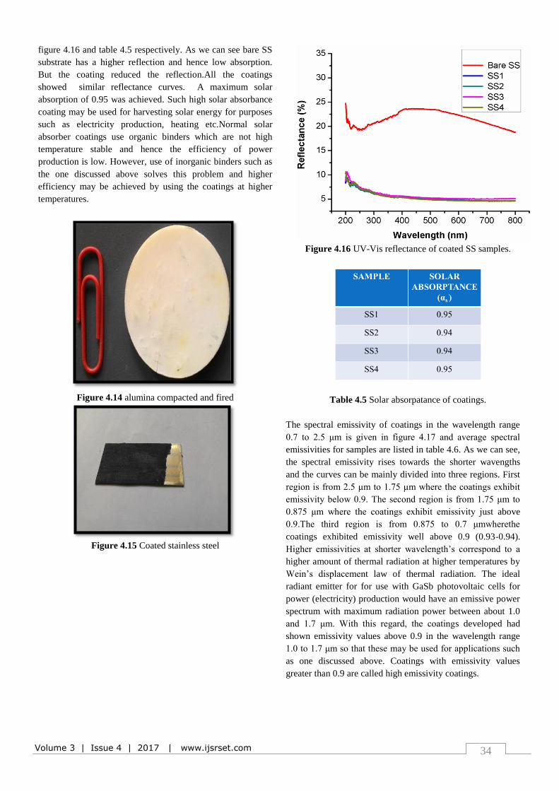
The coatings were brush painted on alumina discs and SS
304 substrates. Alumina powder was compacted and fired for
making alumina with diameter 40 mm and thickness 5 mm
(fig 4.14). The calculated Archimedes density of the alumina
disc was 2.51g/cc. Figure 4.15 shows stainless steel coated
using sodium silicate binder.
Figure 4.13 SEM of black pigment at different
magnifications.
The UV-Visible reflectance and calculated solar absorpatance
for stainless steel coatings named SS1,SS2 so on are given in
a
b
a
b
c
d
Volume 3 | Issue 4 | 2017 | www.ijsrset.com 34
figure 4.16 and table 4.5 respectively. As we can see bare SS
substrate has a higher reflection and hence low absorption.
But the coating reduced the reflection.All the coatings
showed similar reflectance curves. A maximum solar
absorption of 0.95 was achieved. Such high solar absorbance
coating may be used for harvesting solar energy for purposes
such as electricity production, heating etc.Normal solar
absorber coatings use organic binders which are not high
temperature stable and hence the efficiency of power
production is low. However, use of inorganic binders such as
the one discussed above solves this problem and higher
efficiency may be achieved by using the coatings at higher
temperatures.
Figure 4.14 alumina compacted and fired
Figure 4.15 Coated stainless steel
Figure 4.16 UV-Vis reflectance of coated SS samples.
Table 4.5 Solar absorpatance of coatings.
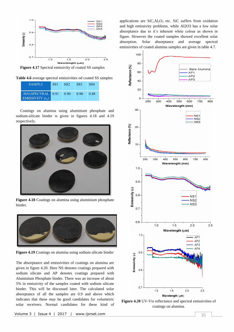
The spectral emissivity of coatings in the wavelength range
0.7 to 2.5 μm is given in figure 4.17 and average spectral
emissivities for samples are listed in table 4.6. As we can see,
the spectral emissivity rises towards the shorter wavengths
and the curves can be mainly divided into three regions. First
region is from 2.5 μm to 1.75 μm where the coatings exhibit
emissivity below 0.9. The second region is from 1.75 μm to
0.875 μm where the coatings exhibit emissivity just above
0.9.The third region is from 0.875 to 0.7 μmwherethe
coatings exhibited emissivity well above 0.9 (0.93-0.94).
Higher emissivities at shorter wavelength’s correspond to a
higher amount of thermal radiation at higher temperatures by
Wein’s displacement law of thermal radiation. The ideal
radiant emitter for for use with GaSb photovoltaic cells for
power (electricity) production would have an emissive power
spectrum with maximum radiation power between about 1.0
and 1.7 μm. With this regard, the coatings developed had
shown emissivity values above 0.9 in the wavelength range
1.0 to 1.7 μm so that these may be used for applications such
as one discussed above. Coatings with emissivity values
greater than 0.9 are called high emissivity coatings.
Volume 3 | Issue 4 | 2017 | www.ijsrset.com 35
Figure 4.17 Spectral emissivity of coated SS samples
Table 4.6 average spectral emissivities od coated SS samples
Coatings on alumina using aluminium phosphate and
sodium-silicate binder is given in figures 4.18 and 4.19
respectively.
Figure 4.18 Coatings on alumina using aluminium phosphate
binder.
Figure 4.19 Coatings on alumina using sodium silicate binder
The absorptance and emissivities of coatings on alumina are
given in figure 4.20. Here NS denotes coatings prepared with
sodium silicate and AP denotes coatings prepared with
Aluminium Phosphate binder. There was an increase of about
5% in emissivity of the samples coated with sodium silicate
binder. This will be discussed later. The calculated solar
absorptance of all the samples are 0.9 and above which
indicates that these may be good candidates for volumetric
solar receivers. Normal candidates for these kind of
applications are SiC,Al2O3 etc. SiC suffers from oxidation
and high emissivity problems, while Al2O3 has a low solar
absorptance due to it’s inherent white colour as shown in
figure. However the coated samples showed excellent solar
absorption. Solar absorptance and average spectral
emissivities of coated alumina samples are given in table 4.7.
Figure 4.20 UV-Vis reflectance and spectral emissivities of
coatings on alumina.
Volume 3 | Issue 4 | 2017 | www.ijsrset.com 36
Table 4.7 Solar absorptance and average spectral emissivity
of coatings on alumina.
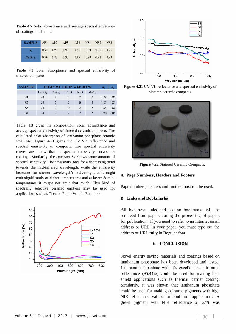
Table 4.8 Solar absorptance and spectral emissivity of
sintered compacts.
Table 4.8 gives the composition, solar absorptance and
average spectral emissivity of sintered ceramic compacts. The
calculated solar absorption of lanthanum phosphate ceramic
was 0.42. Figure 4.21 gives the UV-Vis reflectance and
spectral emissivity of compacts. The spectral emissivity
curves are below that of spectral emissivity curves for
coatings. Similarily, the compact S4 shows some amount of
spectral selectivity. The emissivity goes for a decreasing trend
towards the mid-infrared wavelength, while the emissivity
increases for shorter wavelength’s indicating that it might
emit significantly at higher temperatures and at lower & mid-
temperatures it might not emit that much. This kind of
spectrally selective ceramic emitters may be used for
applications such as Thermo Photo Voltaic Radiators.
Figure 4.21 UV-Vis reflectance and spectral emissivity of
sintered ceramic compacts
Figure 4.22 Sintered Ceramic Compacts.
A. Page Numbers, Headers and Footers
Page numbers, headers and footers must not be used.
B. Links and Bookmarks
All hypertext links and section bookmarks will be
removed from papers during the processing of papers
for publication. If you need to refer to an Internet email
address or URL in your paper, you must type out the
address or URL fully in Regular font.
V. CONCLUSION
Novel energy saving materials and coatings based on
lanthanum phosphate has been developed and tested.
Lanthanum phosphate with it’s excellent near infrared
reflectance (95.44%) could be used for making heat
shield applications such as thermal barrier coating.
Similarily, it was shown that lanthanum phosphate
could be used for making coloured pigments with high
NIR reflectance values for cool roof applications. A
green pigment with NIR reflectance of 67% was
Volume 3 | Issue 4 | 2017 | www.ijsrset.com 37
developed. The black pigment obtained via solid state
reaction method showed L* value of 34.71. The
coatings obtained with black pigment showed high solar
absorbance and high infrared emissivity (both above
0.9). Dark sintered ceramics of lanthanum phosphate
obtained through pigment addition, compaction and
firing showed some amount of spectral selectivity with a
good solar absorption of 0.9 and thermal emissivity of
0.85. The factors affecting emissivity was identified and
studied. Based on the studies, it can be concluded that
rough ceramic coating, with a controlled thickness
on a porous substrate using a viscous binder could
be an excellent emitter.
VI. REFERENCES
[1]. V. D. Kingery, Introduction to ceramics. Cambridge,
Massachusetts: .John Wiley & Sons, 1975.
[2]. W. D. Callister, Fundamentals of Materials Science
and Engineering. United States of America: John
Wiley & Sons, 2001.
[3]. Simmons et. al.: Thermal Protective Coating,US
Patent, July2006.
[4]. Kessman et. al. :Zirconia sol-gel coatings on alumina-
silica refractory material for improved corrosion
resistance,Surface and Coatings Technology, Vol. 204,
2009, pp. 477-483.
[5]. Sudreet. al. : Monazite BasedThermal Barrier Coating,
US Patent,March 2005.
[6]. K. Rajesh et. al. : Synthesis of nanocrystalline
lanthanum phosphate for low temperature densification
to monazite ceramics, Materials Letters,Vol. 58,
2004,pp. 1687-169.
[7]. Mahadiket. al. : Double layerSiO2/Al2O3 high
emissivity coatings on stainless steel substrates using
simple spray deposition system, Applied Surface
Science, Vol. 299, 2014,pp. 6-11.
[8]. Kiomarsipouret.al. : Improvement of spacecraft white
thermal control coatings using the new synthesized Zn-
MCM-41 pigment,Dyes and Pigments, Vol. 96, 2013,
pp. 403-406.
[9]. Cockeram et. al. : The development and testing of
emissivity enhancement coatings for
thermophotovoltaic radiator applications, Thin Solid
Films, Vol. 355-356, 1999, pp. 17-25.
[10]. Pal et. al. :Spectrally selective absorber coating from
transition metal complex for efficient photothermal
conversion, Journal of Materials Science, Vol. 48,
1999, pp. 8268-8276.
[11]. Fend et. al. : Two novel high porosity materials as
volumetric receivers for concentrated solar radiation,
Solar energy Materials and Solar Cells, Vol. 84, 2004,
pp. 291-304.
[12]. Sankar et. al. : Room temperature synthesis of high
temperature stable lanthanum phosphate–yttria nano
composite, Materials Research Bulletin, Vol. 47, 2012,
pp. 1835-1837.
[13]. Sujith et. al. : Porous to dense LaPO4 sintered
ceramics for advanced refractories, Ceramics
International, Vol. 40, 2014, pp. 15121-15129.
[14]. Wang et. al. : Properties and microstructure of
machinable Al2O3/LaPO4ceramic composites,
Ceramics International, Vol. 29, 2003, pp. 19-25.
[15]. Sankar et. al. :Rare earth phosphate based non reactive
and non-wettable surface for molten metals, WO
patent, March 2016.
[16]. Shioyaet. al. : High emissivity refractory coating, US
patent, September 1984.
[17]. Holcombeet. al. : High emissivity coating, US patent,
September 1997.
[18]. Huanget. al. : Enhanced spectral emissivity of CeO2
coating with cauliflower-like microstructure, Applied
Surface Science, Vol. 259, 2012, pp. 301-305.
[19]. Huang et. al. : Highly enhanced infrared spectral
emissivity of porous CeO2 coating, Materials Letters,
Vol. 85, 2012, pp. 57-60.
[20]. Huang et. al. : Enhanced infrared emissivity of CeO2
coatings by La doping, Applied Surface Science , Vol.
280, 2013, pp. 605-609.


![Nano Crystalline Ceramic and Ceramic Coatings …ceramic coatings could also provide improved properties for variety of applications, including wear resistant [9, 10] and thermal barrier](https://img.pdfslide.us/doc/110x75/5fe2e8e4f5c1aa72cd6c774b/nano-crystalline-ceramic-and-ceramic-coatings-ceramic-coatings-could-also-provide.jpg)