Embed Size (px)
Citation preview

Line pulls from 12,000 lb to 300,000 lb
A M O D U L A R L I N E O F H Y D R A U L I C W I N C H E S
Driven to Excellence
Winch & Gear Inc.GEAR DRIVESWINCHES & HOISTSBRAKES & CLUTCHES
LW Series WinchesLANTEC

modularre
liabi
lity
ver
satil
ity q
ualit
yThis catalogue contains detailed sales information on the LANTEC LW Series
Winches. With 20 basic models, a modular design, customizable drums and
flexible input options, LANTEC LW Winches suit many applications.
A M O D U L A R L I N E O F
H Y D R A U L I C W I N C H E S
Fast, dependable delivery with
competitive pricing. LANTEC
is responding to our customer
needs for minimal inventory
and ever shorter lead times.
LANTEC Winch & Gear is a
part of TWG, a global leader
in standard and engineered
winch, gearbox and load
information systems.
LW Series WinchesLANTEC
liftlowerpullposition
ReliabilityExperience
LANTEC … Recognized
worldwide for providing
highly dependable winches,
hoists, and planetary drives
for the most demanding
applications. Over forty years
of technical know-how
and application experience
are brought together
with state-of-the-art
manufacturing techniques
to produce the ultimate
in winch reliability,
versatility and quality.
Our low warranty
cost is the envy of
the winch industry
and is a testament
to our rugged,
reliable design.

modularte
chni
cal d
escr
iptio
n
LANTEC LW Series Winches
house the planetary reduction
gearing and friction brake
externally to the drum barrel
providing for a very versatile
design with the ultimate in
performance flexibility.
For applications that require
drums with a large D:d ratio
(First layer pitch diameter :
Cable diameter) and physical
compactness consider the
LANTEC LH Series Hoists,
with the planetary reduction
gearing and friction brake
housed inside the drum
barrel. A wide range of
models and drum sizes
are available. Please see
separate brochure.
LANTEC LW Series Winches
are suitable for most crane
and lifting applications as well
as pulling and positioning.
They are available with
single drives or dual drives.
Dual drives have two
motors, two brakes, and
two drive modules, for high-
horsepower capability.
The LANTEC LW Series Winches are a
modular construction consisting of:
Cable Drum Steel cable drum running on rolling bearings. Cable is anchored to the drum using a convenient spiral-ferrule type cable anchor.
Winch Base High strength fabricated steel base for flexible design and maximum rigidity.
Drive Module Pre-packaged two-, three- or four-stage, high-efficiency planetary drive with hardened steel internal gears and case carburized sun and planet gears. Planet gears run on rolling bearings which are replaceable independent of the gear itself. Sun gears float to ensure balanced load distribution.
Brake Module Multi-disc, wet friction brake is spring force applied, hydraulic pressure released. Overrunning clutch is large diameter, high capacity, sprag type. Brake module is standard with SAE C or D motor mount. Optional motor mounts are available.
Hydraulic Motor Standard motor is a durable gear motor designed specifically for winching applications with improved starting torque characteristics. LW Series Winches can be fitted with other motor types including 2-speed gear motors, axial and radial piston motors, and motors for low power systems.
Brake Valve Industry’s most stable and reliable counterbalance valve attached directly to the hydraulic motor.
1
construction
When winching in, the Multi-disc Brake remains applied with the hydraulic motor driving directly
into the gear reduction, through an overrunning clutch. When winching stops, the overrunning
clutch locks the input shaft to the already applied Multi-disc Brake ensuring no slippage of the
load. When powering out, the hydraulic motor is pressurized for the opposite rotation. This
pressure is also applied to the Multi-disc Brake, releasing it fully. The Brake Valve then controls
the speed of the load in response to the operator demand. When the operator intends to stop,
the main control valve is moved to neutral, the pressure diminishes, the Brake Valve closes to
stop the load, and the Multi-disc Brake applies as a “parking” brake to positively hold the load.
brake operation
feat
ures
B
A
CDEFG
H I J K
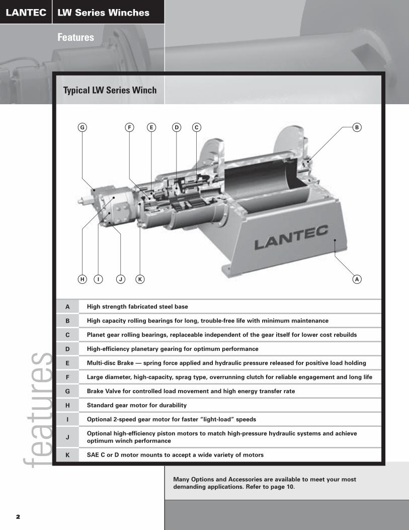
A High strength fabricated steel base
B High capacity rolling bearings for long, trouble-free life with minimum maintenance
C Planet gear rolling bearings, replaceable independent of the gear itself for lower cost rebuilds
D High-efficiency planetary gearing for optimum performance
E Multi-disc Brake — spring force applied and hydraulic pressure released for positive load holding
F Large diameter, high-capacity, sprag type, overrunning clutch for reliable engagement and long life
G Brake Valve for controlled load movement and high energy transfer rate
H Standard gear motor for durability
I Optional 2-speed gear motor for faster “light-load” speeds
JOptional high-efficiency piston motors to match high-pressure hydraulic systems and achieve optimum winch performance
K SAE C or D motor mounts to accept a wide variety of motors
Features
LANTEC
2
Many Options and Accessories are available to meet your most demanding applications. Refer to page 10.
LW Series Winches
Typical LW Series Winch

Drum Dimensions (in) Nominal Wire Rope Diameter (in)
DrumNumber
BarrelDiameter
FlangeDiameter
BetweenFlanges 1/2 5/8 3/4 7/8 1 1 1/8 1 1/4 1 3/8 1 1/2 1 5/8 1 3/4 1 7/8 2 2 1/4 2 1/2
081 8 18 10 681 436 262 185082 8 18 16 1,089 697 419 296083 8 18 24 1,634 1,046 628 444084 8 24 10 1,340 779 541 428085 8 24 16 2,145 1,247 866 684086 8 24 24 3,217 1,870 1,299 1,026101 10 24 10 1,246 778 526 407 312 234102 10 24 16 1,994 1,244 842 651 499 374103 10 24 24 2,991 1,866 1,263 977 748 561104 10 30 14 2,932 1,877 1,255 904 733 495105 10 30 20 4,189 2,681 1,793 1,292 1,047 707106 10 30 30 6,283 4,021 2,689 1,938 1,571 1,061121 12 26 14 1,218 825 637 488 367 268122 12 26 20 1,739 1,178 910 696 524 382123 12 26 30 2,609 1,767 1,364 1,045 785 573124 12 32 14 2,064 1,382 996 806 547 516125 12 32 20 2,949 1,974 1,423 1,152 782 737126 12 32 30 4,423 2,961 2,135 1,728 1,173 1,106141 14 28 14 1,347 913 704 539 406 297 278 196142 14 28 20 1,924 1,304 1,005 770 579 424 398 279143 14 28 30 2,886 1,956 1,508 1,155 869 636 596 419144 14 36 14 2,455 1,676 1,232 1,008 707 563 533 419145 14 36 20 3,507 2,395 1,759 1,440 1,011 804 762 599146 14 36 30 5,261 3,592 2,639 2,160 1,516 1,206 1,142 898161 16 32 14 1,148 900 704 545 413 305 287 203 193162 16 32 20 1,641 1,286 1,005 778 591 436 410 290 275163 16 32 30 2,461 1,929 1,508 1,167 886 653 615 435 413164 16 40 20 3,128 2,130 1,759 1,268 1,027 823 782 617 476165 16 40 30 4,691 3,194 2,639 1,902 1,541 1,234 1,173 926 714166 16 40 40 6,255 4,259 3,519 2,537 2,055 1,645 1,564 1,235 952181 18 34 20 1,394 1,089 843 641 474 445 316 299 285 272182 18 34 30 2,090 1,634 1,265 961 710 668 474 449 427 408183 18 34 40 2,787 2,178 1,686 1,282 947 890 632 598 570 545184 18 42 20 2,285 1,885 1,361 1,103 884 838 663 512 490 471185 18 42 30 3,428 2,827 2,042 1,654 1,325 1,257 994 767 735 707186 18 42 40 4,570 3,770 2,723 2,205 1,767 1,676 1,325 1,023 980 943201 20 36 20 1,501 1,173 908 691 512 480 342 323 307 293 187202 20 36 30 2,252 1,759 1,362 1,037 768 720 512 485 461 440 280203 20 36 40 3,003 2,346 1,816 1,382 1,023 960 683 646 614 586 374204 20 44 20 2,441 2,011 1,454 1,178 944 894 708 548 524 503 364205 20 44 30 3,661 3,016 2,182 1,767 1,417 1,340 1,062 821 785 754 545206 20 44 40 4,881 4,021 2,909 2,356 1,889 1,787 1,415 1,095 1,047 1,005 727241 24 40 20 1,039 792 588 550 393 371 352 335 215 198242 24 40 30 1,558 1,188 882 825 590 557 528 503 322 297243 24 40 40 2,077 1,583 1,176 1,100 786 742 704 670 429 396244 24 48 20 1,641 1,329 1,066 1,005 798 619 591 566 410 285245 24 48 30 2,461 1,993 1,599 1,508 1,197 929 886 848 615 427246 24 48 40 3,281 2,658 2,133 2,011 1,596 1,239 1,181 1,131 820 570301 30 48 24 1,049 980 737 696 503 478 436 283302 30 48 36 1,573 1,470 1,106 1,044 754 716 654 424303 30 48 48 2,097 1,960 1,474 1,391 1,005 955 871 566304 30 60 24 1,999 1,885 1,553 1,264 1,206 968 729 679305 30 60 36 2,999 2,827 2,329 1,896 1,810 1,451 1,093 1,018306 30 60 48 3,998 3,770 3,106 2,528 2,413 1,935 1,458 1,357361 36 54 24 853 803 583 553 503 328362 36 54 36 1,280 1,205 875 829 754 492363 36 54 48 1,706 1,607 1,166 1,106 1,005 656364 36 66 24 1,762 1,436 1,367 1,100 829 769365 36 66 36 2,643 2,154 2,051 1,649 1,244 1,154366 36 66 48 3,523 2,872 2,734 2,199 1,659 1,538421 42 60 36 1,367 995 943 855 560422 42 60 48 1,822 1,327 1,257 1,139 746423 42 60 60 2,278 1,659 1,571 1,424 933424 42 72 36 2,413 2,292 1,847 1,395 1,289425 42 72 48 3,217 3,056 2,463 1,860 1,719426 42 72 60 4,021 3,820 3,079 2,325 2,149481 48 66 36 1,056 955 628482 48 66 54 1,583 1,433 942483 48 66 72 2,111 1,910 1,255484 48 78 36 2,045 1,546 1,425485 48 78 54 3,068 2,319 2,138486 48 78 72 4,090 3,091 2,850ca
ble
drum
cap
aciti
es
3
Cable Drum Capacities
LANTEC
In addition to this list, virtually any drum size is available. Consult LANTEC for recommendation of a cost-effective solution.
Estimated Gross Cable Capacity (ft)
This chart shows the estimated gross cable capacity (feet) of the drum, assuming proper spooling.
Capacities shown assume a full drum, with the top layer of cable not exceeding the flange diameter. No allowance has been made for “free flange” or “free board” which may be dictated by codes or rules relevant to the application. No allowance has been made for “dead” wraps (mandatory minimum of 3 “dead” wraps of cable to be left on the drum at all times).
LANTEC is pleased to provide a layer-by-layer drum capacity chart upon request.
Consult Factory
Not Available
LW Series Winches
Model Drum Size Line Pull (Maximum)
Line Speed(Maximum Allowable)
Line Speed (Maximum with Standard Motor) Basic Output Data Basic Input Data Hydraulic Supply Required with Standard Motor
Drum Number
Barrel Diameter
Flange Diameter 1st Layer Mid Layer Top Layer 1st Layer Mid Layer Top Layer 1st Layer Mid Layer Top Layer Drum Torque
Maximum
Drum Speed Maximum Allowable
Drum Speed Maximum
with Standard Motor
Standard Gear Ratio
Input Torque Maximum Allowable
Input Speed Maximum Allowable
Standard Motor
Maximum Speed
Standard Motor
Displacement
Required Pressure
(Run)
Required Pressure
(Start)
Flow Required at Maximum
Speed
Minimum Flow Required
for Smooth Performance
Recommended Minimum
Flow
in in lb lb lb fpm fpm fpm fpm fpm fpm lb-in rpm rpm lb-in rpm rpm in 3 psi(d) psi(d) gpm gpm gpm
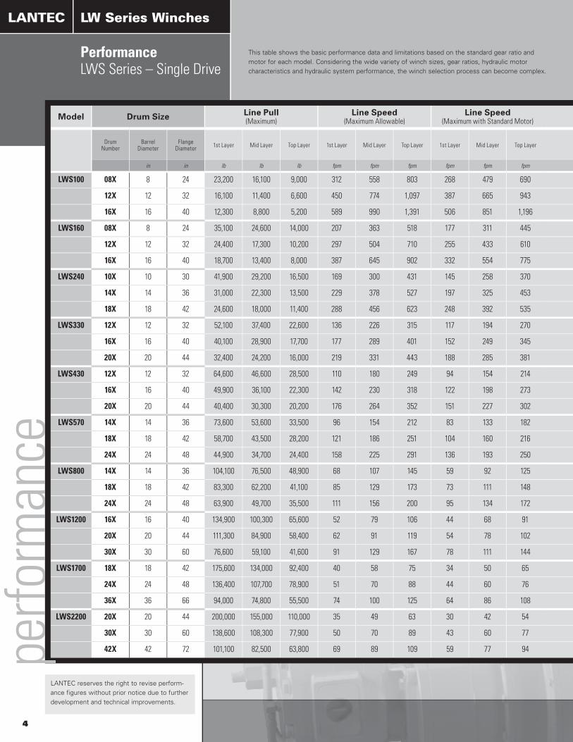
LWS100 08X 8 24 23,200 16,100 9,000 312 558 803 268 479 690 101,500 136 117 23.49 4,500 3,200 2,750 12.3 2,500 2,870 150 28 50
12X 12 32 16,100 11,400 6,600 450 774 1,097 387 665 943 101,500 136 117 23.49 4,500 3,200 2,750 12.3 2,500 2,870 150 28 50
16X 16 40 12,300 8,800 5,200 589 990 1,391 506 851 1,196 101,500 136 117 23.49 4,500 3,200 2,750 12.3 2,500 2,870 150 28 50
LWS160 08X 8 24 35,100 24,600 14,000 207 363 518 177 311 445 155,600 89 76 36.00 4,500 3,200 2,750 12.3 2,500 2,870 150 28 50
12X 12 32 24,400 17,300 10,200 297 504 710 255 433 610 155,600 89 76 36.00 4,500 3,200 2,750 12.3 2,500 2,870 150 28 50
16X 16 40 18,700 13,400 8,000 387 645 902 332 554 775 155,600 89 76 36.00 4,500 3,200 2,750 12.3 2,500 2,870 150 28 50
LWS240 10X 10 30 41,900 29,200 16,500 169 300 431 145 258 370 230,600 59 50 54.46 4,500 3,200 2,750 12.3 2,500 2,870 150 28 50
14X 14 36 31,000 22,300 13,500 229 378 527 197 325 453 230,600 59 50 54.46 4,500 3,200 2,750 12.3 2,500 2,870 150 28 50
18X 18 42 24,600 18,000 11,400 288 456 623 248 392 535 230,600 59 50 54.46 4,500 3,200 2,750 12.3 2,500 2,870 150 28 50
LWS330 12X 12 32 52,100 37,400 22,600 136 226 315 117 194 270 338,400 40 34 79.91 4,500 3,200 2,750 12.3 2,500 2,870 150 28 50
16X 16 40 40,100 28,900 17,700 177 289 401 152 249 345 338,400 40 34 79.91 4,500 3,200 2,750 12.3 2,500 2,870 150 28 50
20X 20 44 32,400 24,200 16,000 219 331 443 188 285 381 338,400 40 34 79.91 4,500 3,200 2,750 12.3 2,500 2,870 150 28 50
LWS430 12X 12 32 64,600 46,600 28,500 110 180 249 94 154 214 424,000 32 27 100.10 4,500 3,200 2,750 12.3 2,500 2,870 150 28 50
16X 16 40 49,900 36,100 22,300 142 230 318 122 198 273 424,000 32 27 100.10 4,500 3,200 2,750 12.3 2,500 2,870 150 28 50
20X 20 44 40,400 30,300 20,200 176 264 352 151 227 302 424,000 32 27 100.10 4,500 3,200 2,750 12.3 2,500 2,870 150 28 50
LWS570 14X 14 36 73,600 53,600 33,500 96 154 212 83 133 182 561,000 24 21 132.55 4,500 3,200 2,750 12.3 2,500 2,870 150 28 50
18X 18 42 58,700 43,500 28,200 121 186 251 104 160 216 561,000 24 21 132.55 4,500 3,200 2,750 12.3 2,500 2,870 150 28 50
24X 24 48 44,900 34,700 24,400 158 225 291 136 193 250 561,000 24 21 132.55 4,500 3,200 2,750 12.3 2,500 2,870 150 28 50
LWS800 14X 14 36 104,100 76,500 48,900 68 107 145 59 92 125 807,000 17 14 190.59 4,500 3,200 2,750 12.3 2,500 2,870 150 28 50
18X 18 42 83,300 62,200 41,100 85 129 173 73 111 148 807,000 17 14 190.59 4,500 3,200 2,750 12.3 2,500 2,870 150 28 50
24X 24 48 63,900 49,700 35,500 111 156 200 95 134 172 807,000 17 14 190.59 4,500 3,200 2,750 12.3 2,500 2,870 150 28 50
LWS1200 16X 16 40 134,900 100,300 65,600 52 79 106 44 68 91 1,197,000 11 10 288.29 4,500 3,200 2,750 12.3 2,500 2,870 150 28 50
20X 20 44 111,300 84,900 58,400 62 91 119 54 78 102 1,197,000 11 10 288.29 4,500 3,200 2,750 12.3 2,500 2,870 150 28 50
30X 30 60 76,600 59,100 41,600 91 129 167 78 111 144 1,197,000 11 10 288.29 4,500 3,200 2,750 12.3 2,500 2,870 150 28 50
LWS1700 18X 18 42 175,600 134,000 92,400 40 58 75 34 50 65 1,756,000 8 7 423.03 4,500 3,200 2,750 12.3 2,500 2,870 150 28 50
24X 24 48 136,400 107,700 78,900 51 70 88 44 60 76 1,756,000 8 7 423.03 4,500 3,200 2,750 12.3 2,500 2,870 150 28 50
36X 36 66 94,000 74,800 55,500 74 100 125 64 86 108 1,756,000 8 7 423.03 4,500 3,200 2,750 12.3 2,500 2,870 150 28 50
LWS2200 20X 20 44 200,000 155,000 110,000 35 49 63 30 42 54 2,200,000 6 5 529.94 4,500 3,200 2,750 12.3 2,500 2,870 150 28 50
30X 30 60 138,600 108,300 77,900 50 70 89 43 60 77 2,200,000 6 5 529.94 4,500 3,200 2,750 12.3 2,500 2,870 150 28 50
42X 42 72 101,100 82,500 63,800 69 89 109 59 77 94 2,200,000 6 5 529.94 4,500 3,200 2,750 12.3 2,500 2,870 150 28 50perfo
rman
ce
4
This table shows the basic performance data and limitations based on the standard gear ratio and motor for each model. Considering the wide variety of winch sizes, gear ratios, hydraulic motor characteristics and hydraulic system performance, the winch selection process can become complex.
LANTEC
LANTEC reserves the right to revise perform-ance figures without prior notice due to further development and technical improvements.
LW Series Winches
PerformanceLWS Series – Single Drive

Model Drum Size Line Pull (Maximum)
Line Speed(Maximum Allowable)
Line Speed (Maximum with Standard Motor) Basic Output Data Basic Input Data Hydraulic Supply Required with Standard Motor
Drum Number
Barrel Diameter
Flange Diameter 1st Layer Mid Layer Top Layer 1st Layer Mid Layer Top Layer 1st Layer Mid Layer Top Layer Drum Torque
Maximum
Drum Speed Maximum Allowable
Drum Speed Maximum
with Standard Motor
Standard Gear Ratio
Input Torque Maximum Allowable
Input Speed Maximum Allowable
Standard Motor
Maximum Speed
Standard Motor
Displacement
Required Pressure
(Run)
Required Pressure
(Start)
Flow Required at Maximum
Speed
Minimum Flow Required
for Smooth Performance
Recommended Minimum
Flow
in in lb lb lb fpm fpm fpm fpm fpm fpm lb-in rpm rpm lb-in rpm rpm in 3 psi(d) psi(d) gpm gpm gpm
LWS100 08X 8 24 23,200 16,100 9,000 312 558 803 268 479 690 101,500 136 117 23.49 4,500 3,200 2,750 12.3 2,500 2,870 150 28 50
12X 12 32 16,100 11,400 6,600 450 774 1,097 387 665 943 101,500 136 117 23.49 4,500 3,200 2,750 12.3 2,500 2,870 150 28 50
16X 16 40 12,300 8,800 5,200 589 990 1,391 506 851 1,196 101,500 136 117 23.49 4,500 3,200 2,750 12.3 2,500 2,870 150 28 50
LWS160 08X 8 24 35,100 24,600 14,000 207 363 518 177 311 445 155,600 89 76 36.00 4,500 3,200 2,750 12.3 2,500 2,870 150 28 50
12X 12 32 24,400 17,300 10,200 297 504 710 255 433 610 155,600 89 76 36.00 4,500 3,200 2,750 12.3 2,500 2,870 150 28 50
16X 16 40 18,700 13,400 8,000 387 645 902 332 554 775 155,600 89 76 36.00 4,500 3,200 2,750 12.3 2,500 2,870 150 28 50
LWS240 10X 10 30 41,900 29,200 16,500 169 300 431 145 258 370 230,600 59 50 54.46 4,500 3,200 2,750 12.3 2,500 2,870 150 28 50
14X 14 36 31,000 22,300 13,500 229 378 527 197 325 453 230,600 59 50 54.46 4,500 3,200 2,750 12.3 2,500 2,870 150 28 50
18X 18 42 24,600 18,000 11,400 288 456 623 248 392 535 230,600 59 50 54.46 4,500 3,200 2,750 12.3 2,500 2,870 150 28 50
LWS330 12X 12 32 52,100 37,400 22,600 136 226 315 117 194 270 338,400 40 34 79.91 4,500 3,200 2,750 12.3 2,500 2,870 150 28 50
16X 16 40 40,100 28,900 17,700 177 289 401 152 249 345 338,400 40 34 79.91 4,500 3,200 2,750 12.3 2,500 2,870 150 28 50
20X 20 44 32,400 24,200 16,000 219 331 443 188 285 381 338,400 40 34 79.91 4,500 3,200 2,750 12.3 2,500 2,870 150 28 50
LWS430 12X 12 32 64,600 46,600 28,500 110 180 249 94 154 214 424,000 32 27 100.10 4,500 3,200 2,750 12.3 2,500 2,870 150 28 50
16X 16 40 49,900 36,100 22,300 142 230 318 122 198 273 424,000 32 27 100.10 4,500 3,200 2,750 12.3 2,500 2,870 150 28 50
20X 20 44 40,400 30,300 20,200 176 264 352 151 227 302 424,000 32 27 100.10 4,500 3,200 2,750 12.3 2,500 2,870 150 28 50
LWS570 14X 14 36 73,600 53,600 33,500 96 154 212 83 133 182 561,000 24 21 132.55 4,500 3,200 2,750 12.3 2,500 2,870 150 28 50
18X 18 42 58,700 43,500 28,200 121 186 251 104 160 216 561,000 24 21 132.55 4,500 3,200 2,750 12.3 2,500 2,870 150 28 50
24X 24 48 44,900 34,700 24,400 158 225 291 136 193 250 561,000 24 21 132.55 4,500 3,200 2,750 12.3 2,500 2,870 150 28 50
LWS800 14X 14 36 104,100 76,500 48,900 68 107 145 59 92 125 807,000 17 14 190.59 4,500 3,200 2,750 12.3 2,500 2,870 150 28 50
18X 18 42 83,300 62,200 41,100 85 129 173 73 111 148 807,000 17 14 190.59 4,500 3,200 2,750 12.3 2,500 2,870 150 28 50
24X 24 48 63,900 49,700 35,500 111 156 200 95 134 172 807,000 17 14 190.59 4,500 3,200 2,750 12.3 2,500 2,870 150 28 50
LWS1200 16X 16 40 134,900 100,300 65,600 52 79 106 44 68 91 1,197,000 11 10 288.29 4,500 3,200 2,750 12.3 2,500 2,870 150 28 50
20X 20 44 111,300 84,900 58,400 62 91 119 54 78 102 1,197,000 11 10 288.29 4,500 3,200 2,750 12.3 2,500 2,870 150 28 50
30X 30 60 76,600 59,100 41,600 91 129 167 78 111 144 1,197,000 11 10 288.29 4,500 3,200 2,750 12.3 2,500 2,870 150 28 50
LWS1700 18X 18 42 175,600 134,000 92,400 40 58 75 34 50 65 1,756,000 8 7 423.03 4,500 3,200 2,750 12.3 2,500 2,870 150 28 50
24X 24 48 136,400 107,700 78,900 51 70 88 44 60 76 1,756,000 8 7 423.03 4,500 3,200 2,750 12.3 2,500 2,870 150 28 50
36X 36 66 94,000 74,800 55,500 74 100 125 64 86 108 1,756,000 8 7 423.03 4,500 3,200 2,750 12.3 2,500 2,870 150 28 50
LWS2200 20X 20 44 200,000 155,000 110,000 35 49 63 30 42 54 2,200,000 6 5 529.94 4,500 3,200 2,750 12.3 2,500 2,870 150 28 50
30X 30 60 138,600 108,300 77,900 50 70 89 43 60 77 2,200,000 6 5 529.94 4,500 3,200 2,750 12.3 2,500 2,870 150 28 50
42X 42 72 101,100 82,500 63,800 69 89 109 59 77 94 2,200,000 6 5 529.94 4,500 3,200 2,750 12.3 2,500 2,870 150 28 50
5
LANTEC recommends allowing our Sales & Application Engineering professionals to assist in determining the winch model and options that satisfy your most demanding applications. LANTEC will be pleased to supply a detailed specification sheet specifically for your application.

Model Drum Size Line Pull (Maximum)
Line Speed(Maximum Allowable)
Line Speed (Maximum with Standard Motor) Basic Output Data Basic Input Data Hydraulic Supply Required with Standard Motor
Drum Number
Barrel Diameter
Flange Diameter 1st Layer Mid Layer Top Layer 1st Layer Mid Layer Top Layer 1st Layer Mid Layer Top Layer Drum Torque
Maximum
Drum Speed Maximum Allowable
Drum Speed Maximum
with Standard Motor
Standard Gear Ratio
Input Torque Maximum Allowable
Input Speed Maximum Allowable
Standard Motor
Maximum Speed
Standard Motor
Displacement
Required Pressure
(Run)
Required Pressure
(Start)
Flow Required at Maximum
Speed
Minimum Flow Required
for Smooth Performance
Recommended Minimum
Flow
in in lb lb lb fpm fpm fpm fpm fpm fpm lb-in rpm rpm lb-in rpm rpm in 3 psi(d) psi(d) gpm gpm gpm
LWD200 10X 10 30 37,300 25,900 14,400 388 698 1,008 333 600 866 203,000 136 117 23.49 4,500 3,200 2,750 12.3 2,500 2,870 300 56 100
14X 14 36 27,500 19,700 11,800 526 878 1,230 452 755 1,057 203,000 136 117 23.49 4,500 3,200 2,750 12.3 2,500 2,870 300 56 100
18X 18 42 21,700 15,900 10,000 669 1,057 1,444 575 908 1,241 203,000 136 117 23.49 4,500 3,200 2,750 12.3 2,500 2,870 300 56 100
LWD310 12X 12 32 47,800 34,300 20,700 303 501 698 260 430 600 311,000 89 76 36.00 4,500 3,200 2,750 12.3 2,500 2,870 300 56 100
16X 16 40 36,900 26,600 16,300 393 642 890 337 551 765 311,000 89 76 36.00 4,500 3,200 2,750 12.3 2,500 2,870 300 56 100
20X 20 44 29,800 22,300 14,700 486 735 983 417 631 845 311,000 89 76 36.00 4,500 3,200 2,750 12.3 2,500 2,870 300 56 100
LWD460 12X 12 32 69,600 50,500 31,300 204 329 454 175 283 390 461,000 59 50 54.46 4,500 3,200 2,750 12.3 2,500 2,870 300 56 100
16X 16 40 53,800 39,100 24,400 263 422 581 226 363 499 461,000 59 50 54.46 4,500 3,200 2,750 12.3 2,500 2,870 300 56 100
20X 20 44 43,900 33,000 22,000 323 485 646 278 417 555 461,000 59 50 54.46 4,500 3,200 2,750 12.3 2,500 2,870 300 56 100
LWD680 14X 14 36 88,100 64,400 40,700 161 255 349 139 220 300 677,000 40 34 79.91 4,500 3,200 2,750 12.3 2,500 2,870 300 56 100
18X 18 42 70,300 52,300 34,300 202 308 414 173 265 356 677,000 40 34 79.91 4,500 3,200 2,750 12.3 2,500 2,870 300 56 100
24X 24 48 53,900 41,800 29,600 263 372 480 226 319 412 677,000 40 34 79.91 4,500 3,200 2,750 12.3 2,500 2,870 300 56 100
LWD850 14X 14 36 109,400 80,400 51,400 130 203 276 111 174 237 848,000 32 27 100.10 4,500 3,200 2,750 12.3 2,500 2,870 300 56 100
18X 18 42 87,500 65,400 43,200 162 245 328 139 211 282 848,000 32 27 100.10 4,500 3,200 2,750 12.3 2,500 2,870 300 56 100
24X 24 48 67,200 52,300 37,300 211 296 381 182 255 327 848,000 32 27 100.10 4,500 3,200 2,750 12.3 2,500 2,870 300 56 100
LWD1100 16X 16 40 127,400 94,300 61,100 111 172 232 96 148 200 1,123,000 24 21 132.55 4,500 3,200 2,750 12.3 2,500 2,870 300 56 100
20X 20 44 104,500 79,700 54,800 136 198 259 117 170 223 1,123,000 24 21 132.55 4,500 3,200 2,750 12.3 2,500 2,870 300 56 100
30X 30 60 71,900 55,500 39,100 198 281 363 170 241 312 1,123,000 24 21 132.55 4,500 3,200 2,750 12.3 2,500 2,870 300 56 100
LWD1600 18X 18 42 162,400 123,400 84,400 87 128 168 75 110 144 1,614,000 17 14 190.59 4,500 3,200 2,750 12.3 2,500 2,870 300 56 100
24X 24 48 126,000 99,100 72,100 113 155 197 97 133 169 1,614,000 17 14 190.59 4,500 3,200 2,750 12.3 2,500 2,870 300 56 100
36X 36 66 86,400 68,700 51,000 164 221 278 141 190 239 1,614,000 17 14 190.59 4,500 3,200 2,750 12.3 2,500 2,870 300 56 100
LWD2400 24X 24 48 184,100 146,500 108,800 76 102 128 65 88 110 2,393,000 11 10 288.29 4,500 3,200 2,750 12.3 2,500 2,870 300 56 100
36X 36 66 127,200 101,800 76,300 109 146 182 94 126 157 2,393,000 11 10 288.29 4,500 3,200 2,750 12.3 2,500 2,870 300 56 100
48X 48 78 96,900 80,300 63,600 143 181 219 123 156 188 2,393,000 11 10 288.29 4,500 3,200 2,750 12.3 2,500 2,870 300 56 100
LWD3500 24X 24 48 265,100 214,200 163,300 52 69 85 45 59 73 3,512,000 8 7 423.03 4,500 3,200 2,750 12.3 2,500 2,870 300 56 100
36X 36 66 184,800 149,100 113,300 75 99 123 65 86 106 3,512,000 8 7 423.03 4,500 3,200 2,750 12.3 2,500 2,870 300 56 100
48X 48 78 141,200 117,800 94,300 99 124 148 85 106 127 3,512,000 8 7 423.03 4,500 3,200 2,750 12.3 2,500 2,870 300 56 100
LWD4400 30X 30 60 270,700 215,400 160,000 51 69 87 44 60 75 4,399,000 6 5 529.94 4,500 3,200 2,750 12.3 2,500 2,870 300 56 100
42X 42 72 200,000 164,700 129,400 70 89 107 60 76 92 4,399,000 6 5 529.94 4,500 3,200 2,750 12.3 2,500 2,870 300 56 100
48X 48 78 176,000 147,500 118,900 79 98 117 68 85 101 4,399,000 6 5 529.94 4,500 3,200 2,750 12.3 2,500 2,870 300 56 100perfo
rman
ceLANTEC LW Series Winches
This table shows the basic performance data and limitations based on the standard gear ratio and motor for each model. Considering the wide variety of winch sizes, gear ratios, hydraulic motor characteristics and hydraulic system performance, the winch selection process can become complex.
6
LANTEC reserves the right to revise perform-ance figures without prior notice due to further development and technical improvements.
PerformanceLWD Series – Dual Drive

Model Drum Size Line Pull (Maximum)
Line Speed(Maximum Allowable)
Line Speed (Maximum with Standard Motor) Basic Output Data Basic Input Data Hydraulic Supply Required with Standard Motor
Drum Number
Barrel Diameter
Flange Diameter 1st Layer Mid Layer Top Layer 1st Layer Mid Layer Top Layer 1st Layer Mid Layer Top Layer Drum Torque
Maximum
Drum Speed Maximum Allowable
Drum Speed Maximum
with Standard Motor
Standard Gear Ratio
Input Torque Maximum Allowable
Input Speed Maximum Allowable
Standard Motor
Maximum Speed
Standard Motor
Displacement
Required Pressure
(Run)
Required Pressure
(Start)
Flow Required at Maximum
Speed
Minimum Flow Required
for Smooth Performance
Recommended Minimum
Flow
in in lb lb lb fpm fpm fpm fpm fpm fpm lb-in rpm rpm lb-in rpm rpm in 3 psi(d) psi(d) gpm gpm gpm
LWD200 10X 10 30 37,300 25,900 14,400 388 698 1,008 333 600 866 203,000 136 117 23.49 4,500 3,200 2,750 12.3 2,500 2,870 300 56 100
14X 14 36 27,500 19,700 11,800 526 878 1,230 452 755 1,057 203,000 136 117 23.49 4,500 3,200 2,750 12.3 2,500 2,870 300 56 100
18X 18 42 21,700 15,900 10,000 669 1,057 1,444 575 908 1,241 203,000 136 117 23.49 4,500 3,200 2,750 12.3 2,500 2,870 300 56 100
LWD310 12X 12 32 47,800 34,300 20,700 303 501 698 260 430 600 311,000 89 76 36.00 4,500 3,200 2,750 12.3 2,500 2,870 300 56 100
16X 16 40 36,900 26,600 16,300 393 642 890 337 551 765 311,000 89 76 36.00 4,500 3,200 2,750 12.3 2,500 2,870 300 56 100
20X 20 44 29,800 22,300 14,700 486 735 983 417 631 845 311,000 89 76 36.00 4,500 3,200 2,750 12.3 2,500 2,870 300 56 100
LWD460 12X 12 32 69,600 50,500 31,300 204 329 454 175 283 390 461,000 59 50 54.46 4,500 3,200 2,750 12.3 2,500 2,870 300 56 100
16X 16 40 53,800 39,100 24,400 263 422 581 226 363 499 461,000 59 50 54.46 4,500 3,200 2,750 12.3 2,500 2,870 300 56 100
20X 20 44 43,900 33,000 22,000 323 485 646 278 417 555 461,000 59 50 54.46 4,500 3,200 2,750 12.3 2,500 2,870 300 56 100
LWD680 14X 14 36 88,100 64,400 40,700 161 255 349 139 220 300 677,000 40 34 79.91 4,500 3,200 2,750 12.3 2,500 2,870 300 56 100
18X 18 42 70,300 52,300 34,300 202 308 414 173 265 356 677,000 40 34 79.91 4,500 3,200 2,750 12.3 2,500 2,870 300 56 100
24X 24 48 53,900 41,800 29,600 263 372 480 226 319 412 677,000 40 34 79.91 4,500 3,200 2,750 12.3 2,500 2,870 300 56 100
LWD850 14X 14 36 109,400 80,400 51,400 130 203 276 111 174 237 848,000 32 27 100.10 4,500 3,200 2,750 12.3 2,500 2,870 300 56 100
18X 18 42 87,500 65,400 43,200 162 245 328 139 211 282 848,000 32 27 100.10 4,500 3,200 2,750 12.3 2,500 2,870 300 56 100
24X 24 48 67,200 52,300 37,300 211 296 381 182 255 327 848,000 32 27 100.10 4,500 3,200 2,750 12.3 2,500 2,870 300 56 100
LWD1100 16X 16 40 127,400 94,300 61,100 111 172 232 96 148 200 1,123,000 24 21 132.55 4,500 3,200 2,750 12.3 2,500 2,870 300 56 100
20X 20 44 104,500 79,700 54,800 136 198 259 117 170 223 1,123,000 24 21 132.55 4,500 3,200 2,750 12.3 2,500 2,870 300 56 100
30X 30 60 71,900 55,500 39,100 198 281 363 170 241 312 1,123,000 24 21 132.55 4,500 3,200 2,750 12.3 2,500 2,870 300 56 100
LWD1600 18X 18 42 162,400 123,400 84,400 87 128 168 75 110 144 1,614,000 17 14 190.59 4,500 3,200 2,750 12.3 2,500 2,870 300 56 100
24X 24 48 126,000 99,100 72,100 113 155 197 97 133 169 1,614,000 17 14 190.59 4,500 3,200 2,750 12.3 2,500 2,870 300 56 100
36X 36 66 86,400 68,700 51,000 164 221 278 141 190 239 1,614,000 17 14 190.59 4,500 3,200 2,750 12.3 2,500 2,870 300 56 100
LWD2400 24X 24 48 184,100 146,500 108,800 76 102 128 65 88 110 2,393,000 11 10 288.29 4,500 3,200 2,750 12.3 2,500 2,870 300 56 100
36X 36 66 127,200 101,800 76,300 109 146 182 94 126 157 2,393,000 11 10 288.29 4,500 3,200 2,750 12.3 2,500 2,870 300 56 100
48X 48 78 96,900 80,300 63,600 143 181 219 123 156 188 2,393,000 11 10 288.29 4,500 3,200 2,750 12.3 2,500 2,870 300 56 100
LWD3500 24X 24 48 265,100 214,200 163,300 52 69 85 45 59 73 3,512,000 8 7 423.03 4,500 3,200 2,750 12.3 2,500 2,870 300 56 100
36X 36 66 184,800 149,100 113,300 75 99 123 65 86 106 3,512,000 8 7 423.03 4,500 3,200 2,750 12.3 2,500 2,870 300 56 100
48X 48 78 141,200 117,800 94,300 99 124 148 85 106 127 3,512,000 8 7 423.03 4,500 3,200 2,750 12.3 2,500 2,870 300 56 100
LWD4400 30X 30 60 270,700 215,400 160,000 51 69 87 44 60 75 4,399,000 6 5 529.94 4,500 3,200 2,750 12.3 2,500 2,870 300 56 100
42X 42 72 200,000 164,700 129,400 70 89 107 60 76 92 4,399,000 6 5 529.94 4,500 3,200 2,750 12.3 2,500 2,870 300 56 100
48X 48 78 176,000 147,500 118,900 79 98 117 68 85 101 4,399,000 6 5 529.94 4,500 3,200 2,750 12.3 2,500 2,870 300 56 100
LANTEC recommends allowing our Sales & Application Engineering professionals to assist in determining the winch model and options that satisfy your most demanding applications. LANTEC will be pleased to supply a detailed specification sheet specifically for your application.
7

ModelMinimum Flange
DiameterOverall Height
Overall Width
Overall Length
Drum Centerline to Motor End
Drum Axis to Mounting Pads
Base Length
B D E F G H J
All dimensions are in inches.
LWS100 16 B + 1 7/8 B + 5 3/8 C + 41 1/8 C/2 + 34 1/2 B/2 + 1 7/8 C + 13 1/8
LWS160 17 1/4 B + 1 7/8 B + 5 3/8 C + 41 5/8 C/2 + 35 1/8 B/2 + 1 7/8 C + 13 1/8
LWS240 19 1/4 B + 1 7/8 B + 5 3/8 C + 45 C/2 + 38 3/8 B/2 + 1 7/8 C + 13 1/8
LWS330 22 B + 2 1/4 B + 6 1/2 C + 45 3/4 C/2 + 39 1/8 B/2 + 2 1/4 C + 13 1/8
LWS430 22 B + 2 1/4 B + 6 1/2 C + 45 3/4 C/2 + 39 1/8 B/2 + 2 1/4 C + 13 1/8
LWS570 22 B + 2 1/4 B + 6 1/2 C + 49 7/8 C/2 + 43 1/4 B/2 + 2 1/4 C + 13 1/8
LWS800 26 1/4 B + 2 1/4 B + 6 1/2 C + 51 1/8 C/2 + 44 3/8 B/2 + 2 1/4 C + 13 1/2
LWS1200 30 1/2 B + 2 1/4 B + 7 1/2 C + 56 3/8 C/2 + 49 3/8 B/2 + 2 1/4 C + 14
LWS1700 34 1/2 B + 2 1/4 B + 7 1/2 C + 57 5/8 C/2 + 50 5/8 B/2 + 2 1/4 C + 14
LWS2200 34 1/2 B + 2 1/4 B + 7 1/2 C + 60 7/8 C/2 + 53 3/8 B/2 + 2 1/4 C + 15
Dia
gram
LW
S Se
ries
To Determine Winch Dimensions
FIRST
Use the Cable Capacity Chart on page 3 to select the …
Barrel Diameter (A)
Flange Diameter (B) (subject to the minimum per table above)
Drum Length Between Flanges (C)
SECOND
Use the formula in the table above to calculate the approximate winch dimensions.
B = Drum Flange Diameter
C = Drum Length Between Flanges
sing
le d
rive
The dimensions shown are for general information. Only a detailed Certified Installation Drawing, specific to your winch, should be used for final installation dimensions. Certified Installation Drawings are available from LANTEC upon request.
Dimensional DataLWS Series – Single Drive
LANTEC
Specifications subject to change without notice and without incurring obligation. Rely only on a Certified Installation Drawing for accurate and current dimensions.
8
LW Series Winches
9
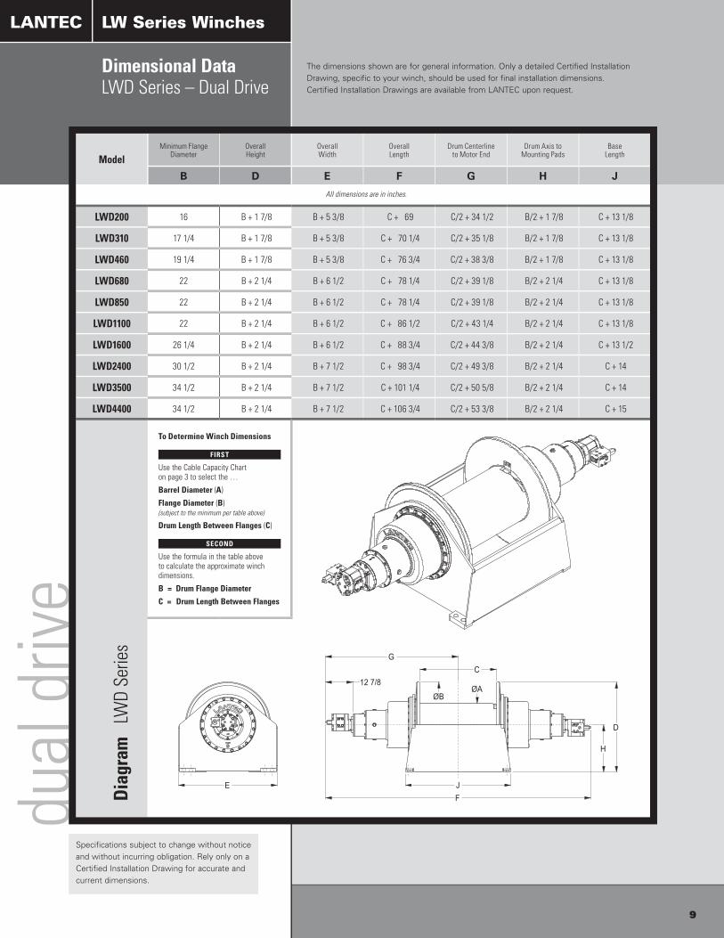
ModelMinimum Flange
DiameterOverall Height
Overall Width
Overall Length
Drum Centerline to Motor End
Drum Axis to Mounting Pads
Base Length
B D E F G H J
All dimensions are in inches.
LWD200 16 B + 1 7/8 B + 5 3/8 C + 69 C/2 + 34 1/2 B/2 + 1 7/8 C + 13 1/8
LWD310 17 1/4 B + 1 7/8 B + 5 3/8 C + 70 1/4 C/2 + 35 1/8 B/2 + 1 7/8 C + 13 1/8
LWD460 19 1/4 B + 1 7/8 B + 5 3/8 C + 76 3/4 C/2 + 38 3/8 B/2 + 1 7/8 C + 13 1/8
LWD680 22 B + 2 1/4 B + 6 1/2 C + 78 1/4 C/2 + 39 1/8 B/2 + 2 1/4 C + 13 1/8
LWD850 22 B + 2 1/4 B + 6 1/2 C + 78 1/4 C/2 + 39 1/8 B/2 + 2 1/4 C + 13 1/8
LWD1100 22 B + 2 1/4 B + 6 1/2 C + 86 1/2 C/2 + 43 1/4 B/2 + 2 1/4 C + 13 1/8
LWD1600 26 1/4 B + 2 1/4 B + 6 1/2 C + 88 3/4 C/2 + 44 3/8 B/2 + 2 1/4 C + 13 1/2
LWD2400 30 1/2 B + 2 1/4 B + 7 1/2 C + 98 3/4 C/2 + 49 3/8 B/2 + 2 1/4 C + 14
LWD3500 34 1/2 B + 2 1/4 B + 7 1/2 C + 101 1/4 C/2 + 50 5/8 B/2 + 2 1/4 C + 14
LWD4400 34 1/2 B + 2 1/4 B + 7 1/2 C + 106 3/4 C/2 + 53 3/8 B/2 + 2 1/4 C + 15
Dia
gram
LW
D Se
ries
To Determine Winch Dimensions
FIRST
Use the Cable Capacity Chart on page 3 to select the …
Barrel Diameter (A)
Flange Diameter (B) (subject to the minimum per table above)
Drum Length Between Flanges (C)
SECOND
Use the formula in the table above to calculate the approximate winch dimensions.
B = Drum Flange Diameter
C = Drum Length Between Flanges
dual
driv
eDimensional DataLWD Series – Dual Drive
LANTEC
The dimensions shown are for general information. Only a detailed Certified Installation Drawing, specific to your winch, should be used for final installation dimensions. Certified Installation Drawings are available from LANTEC upon request.
Specifications subject to change without notice and without incurring obligation. Rely only on a Certified Installation Drawing for accurate and current dimensions.
LW Series Winches

optio
ns &
acc
esso
ries
10
Options & Accessories
LANTEC
LANTEC LW Series Winches are available with a wide variety of optional
configurations and accessories to create the winch that meets all your needs.
® LeBus and the Grooved Sleeve design are Registered Trademarks of LeBus International Inc.
Drum Configurations Beyond the range of standard drums, LANTEC offers:• Alternate drum sizes quickly and efficiently manufactured to match your cable storage requirements• Special cable anchoring methods including synthetic rope anchoring• Multiple cable anchors for multiple cable or “On-Off” applications• Drum divider for multiple cable applications• Grooved drums with spiral grooving• LeBus® parallel groove drum sleeves
Optional Gear Ratios LANTEC offers optional gear ratios to permit the most economical matching of performance requirements with the available hydraulic power and motor selection.
Hydraulic Motor LANTEC supplies the winch with a hydraulic motor that matches the customer’s hydraulic system to provide optimum performance. Winches are also available without motors for customers who prefer to supply their own.
Motor Mounting Configurations LANTEC provides either an SAE C or D motor mount. Other motor mounting configurations are available to support most hydraulic motors including DIN and ISO standards.
Ratchet & Pawl LANTEC offers a spring engaged, hydraulic pressure released ratchet and pawl package. Manual operation is also available.
Multi-disc Brake LANTEC includes a standard multi-disc, friction brake with a sprag type, overrunning clutch for optimum performance in most applications. The brake is available without the overrunning clutch for applications requiring a brake effective in both directions, such as slewing, vanging or positioning.
Drum Brake LANTEC offers a band brake acting directly on the drum. Band brakes are available with a variety of actuator types and in “marine duty” configurations.
Levelwind LANTEC provides a powered levelwind device to assist in proper cable spooling for applications with a large fleet angle.
Drum Pressure Roller LANTEC provides a roller, forced into contact with the cable on the drum by adjustable springs to help prevent “birdsnesting” and assist with cable spooling. This option is also available with sensors indicating top and bottom layer conditions.
Encoder Drive LANTEC offers a light duty output shaft for driving a rotary encoder to monitor winch drum speed and/or position.
LW Series Winches
mot
or s
elec
tion
2-Sp
eed
Mot
orPi
ston
– F
ixed
Dis
plac
emen
t
Elec
tric
Mot
orRa
dial
Pis
ton
– Fi
xed
and
Varia
ble
Dis
plac
emen
t
Pist
on –
Var
iabl
e D
ispl
acem
ent
Stan
dard
Mot
or
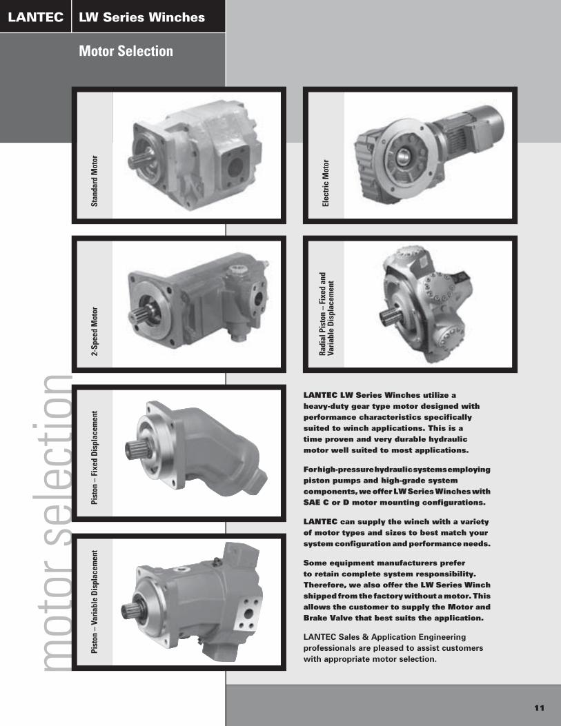
Motor Selection
LANTEC LW Series Winches utilize a heavy-duty gear type motor designed with performance characteristics specifically suited to winch applications. This is a time proven and very durable hydraulic motor well suited to most applications.
For high-pressure hydraulic systems employing piston pumps and high-grade system components, we offer LW Series Winches with SAE C or D motor mounting configurations.
LANTEC can supply the winch with a variety of motor types and sizes to best match your system configuration and performance needs.
Some equipment manufacturers prefer to retain complete system responsibility. Therefore, we also offer the LW Series Winch shipped from the factory without a motor. This allows the customer to supply the Motor and Brake Valve that best suits the application.
LANTEC Sales & Application Engineering professionals are pleased to assist customers with appropriate motor selection.
LANTEC
11
LW Series Winches

Winch Assembly (Supplied by LANTEC) Winch Assembly (Supplied by LANTEC)
WinchFrictionBrake
WinchBrakeValve
WinchMotor
WinchFrictionBrake
WinchBrakeValve
WinchMotor
Control ValveControl Valve
Relief ValveRelief Valve
PumpPump
Winch Assembly (Supplied by LANTEC) Winch Assembly (Supplied by LANTEC)
WinchFrictionBrake
WinchBrakeValve
WinchMotor
WinchFrictionBrake
WinchBrakeValve
WinchMotor
Control ValveControl Valve
Relief ValveRelief Valve
PumpPump
inst
alla
tion
PartsServiceInstallation
LANTEC
LANTEC provides in-factory service and rebuild of your winch
including visual inspection, magnetic particle inspection,
rebuilding, testing, recertification and recoating.
Factory Authorized Service Centers are conveniently
located with factory-trained service personnel to perform
troubleshooting, inspection and service.
LANTEC stocks all wear parts
for quick shipment to any
location world wide. Expedited
parts service is available
for same day shipment if
ordered by 11:00 am (PST).
Our Parts professionals work
hard to ensure you receive the
correct parts for your winch.
When a winch serial number
is provided with your order we
crosscheck to ensure you have
ordered the right parts for the job.
12
parts service
LW Series Winches
LANTEC LW Series Winches must be installed in strict accordance with our written installation instructions. The winch must be connected to a suitable hydraulic power supply. Caution: these circuit examples are for illustration purposes only and may not contain all components required for full system function.
Typ
ical
Hyd
rau
lic C
ircu
it f
or
Sta
nd
ard
Mo
tor
Typ
ical
Hyd
rau
lic C
ircu
it f
or
2-S
pee
d M
oto
r
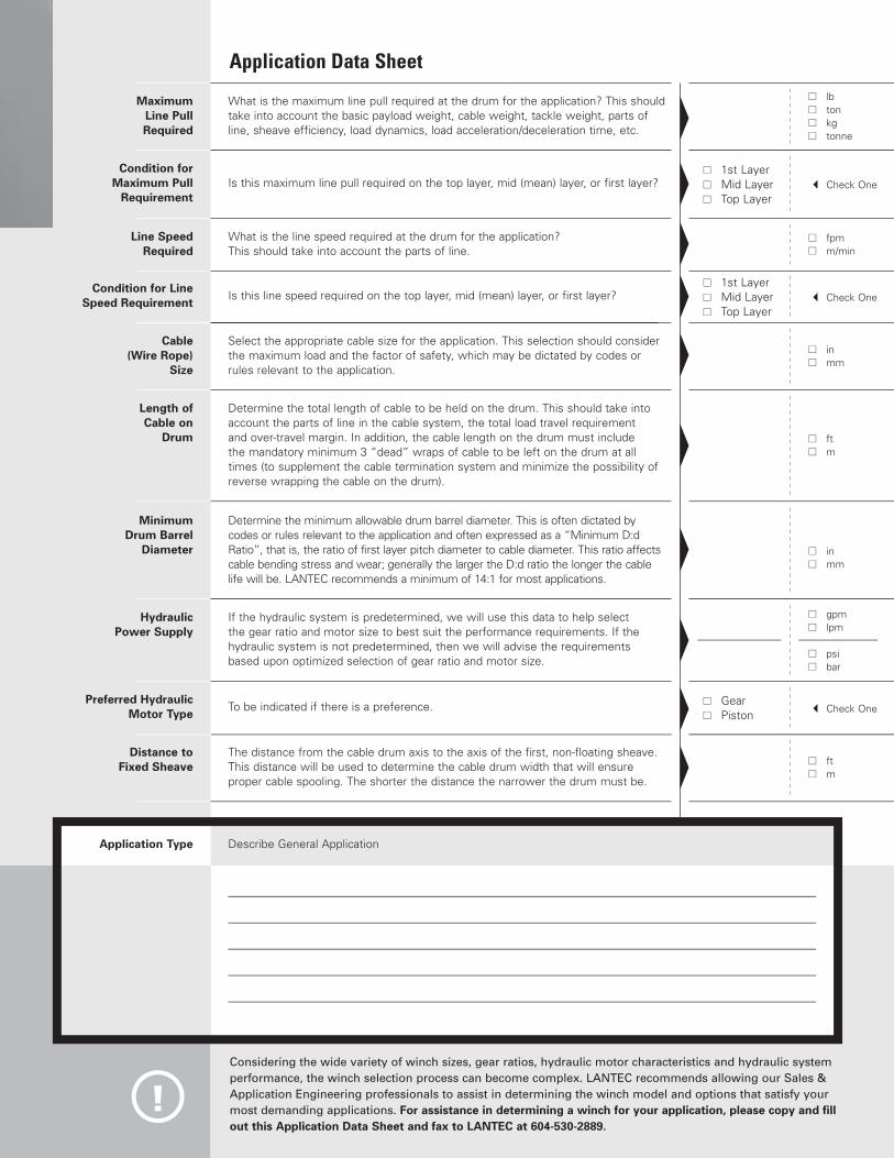
What is the maximum line pull required at the drum for the application? This should take into account the basic payload weight, cable weight, tackle weight, parts of line, sheave efficiency, load dynamics, load acceleration/deceleration time, etc.
Maximum Line Pull Required
Condition for Maximum Pull
Requirement
Hydraulic Power Supply
lb ton kg tonne
gpm lpm
psi bar
Is this maximum line pull required on the top layer, mid (mean) layer, or first layer?
MinimumDrum Barrel
Diameter in mm
Determine the minimum allowable drum barrel diameter. This is often dictated by codes or rules relevant to the application and often expressed as a “Minimum D:d Ratio”, that is, the ratio of first layer pitch diameter to cable diameter. This ratio affects cable bending stress and wear; generally the larger the D:d ratio the longer the cable life will be. LANTEC recommends a minimum of 14:1 for most applications.
If the hydraulic system is predetermined, we will use this data to help select the gear ratio and motor size to best suit the performance requirements. If the hydraulic system is not predetermined, then we will advise the requirements based upon optimized selection of gear ratio and motor size.
Cable (Wire Rope)
Size
in mm
Select the appropriate cable size for the application. This selection should consider the maximum load and the factor of safety, which may be dictated by codes or rules relevant to the application.
Length of Cable on
Drum ft m
Determine the total length of cable to be held on the drum. This should take into account the parts of line in the cable system, the total load travel requirement and over-travel margin. In addition, the cable length on the drum must include the mandatory minimum 3 “dead” wraps of cable to be left on the drum at all times (to supplement the cable termination system and minimize the possibility of reverse wrapping the cable on the drum).
Distance to Fixed Sheave ft
m
The distance from the cable drum axis to the axis of the first, non-floating sheave. This distance will be used to determine the cable drum width that will ensure proper cable spooling. The shorter the distance the narrower the drum must be.
Check One 1st Layer Mid Layer Top Layer
Condition for Line Speed Requirement
Is this line speed required on the top layer, mid (mean) layer, or first layer? Check One 1st Layer Mid Layer Top Layer
Preferred Hydraulic Motor Type
To be indicated if there is a preference. Check One Gear Piston
Application Data Sheet
!
fpm m/min
Line Speed Required
What is the line speed required at the drum for the application? This should take into account the parts of line.
Considering the wide variety of winch sizes, gear ratios, hydraulic motor characteristics and hydraulic system performance, the winch selection process can become complex. LANTEC recommends allowing our Sales & Application Engineering professionals to assist in determining the winch model and options that satisfy your most demanding applications. For assistance in determining a winch for your application, please copy and fill out this Application Data Sheet and fax to LANTEC at 604-530-2889.
Application Type Describe General Application

20040 0604
P R O U D L Y D I S T R I B U T E D B Y
LANTEC LH Series Hoists are a family of hoists specifically designed for
crane applications. With Line Pulls from 12,000 to 72,000 lbs, there’s an LH
Hoist to suit the most demanding application. Many models have mounting
dimensions directly interchangeable with competitive brands.
Please contact LANTEC for more information.
LANTEC Planetary Drives are manufactured to meet your application.
Current designs include output torques from 10,000 to 500,000 lb-ft. A long
history of successful projects assures you of high quality and dependability.
Please contact LANTEC for more information.
Many of our winch models readily accept electric motors. Today's
modern electric drives are well suited for use on winches. If your application
requires electric drives, let LANTEC show you our economical solutions.
Please contact LANTEC for more information.
LANTEC has been designing custom winches for over 40 years.
This tremendous experience allows us to assist you in designing and
manufacturing the ideal winch for your most demanding projects.
LH Series HoistsLANTEC
Planetary DrivesLANTEC
Electric WinchesLANTEC
Custom WinchesLANTEC
LANTECWinch & Gear Inc.
5827 Production WayLangley, BC V3A 4N5Canada
Tel (604) 530-0737Fax (604) 530-2889
© 2004 Copyright LANTEC. All rights reserved.