Embed Size (px)
Citation preview

Planning and Cabling Networks
LANs - Making the Physical Connection
Choosing the Appropriate LAN Device
For this course, the choice of which router to deploy is determined by the Ethernet interfaces that match the
technology of the switches at the center of the LAN. It is important to note that routers offer many services
and features to the LAN. These services and features are covered in the more advanced courses. Each LAN
will have a router as its gateway connecting the LAN to other networks. Inside the LAN will be one or more
hubs or switches to connect the end devices to the LAN.
Internetwork Devices
Routers are the primary devices used to interconnect networks. Each port on a router connects to a different
network and routes packets between the networks. Routers have the ability to break up broadcast domains
and collision domains. Routers are also used to interconnect networks that use different technologies. They
can have both LAN and WAN interfaces. The router's LAN interfaces allow routers to connect to the LAN
media. This is usually UTP cabling, but modules can be added for using fiber-optics. Depending on the
series or model of router, there can be multiple interface types for connection of LAN and WAN cabling.

Intranetwork Devices
To create a LAN, we need to select the appropriate devices to connect the end device to the network. The
two most common devices used are hubs and switches.
Hub
A hub receives a signal, regenerates it, and sends the signal over all ports. The use of hubs creates a logical
bus. This means that the LAN uses multiaccess media. The ports use a shared bandwidth approach and often
have reduced performance in the LAN due to collisions and recovery. Although multiple hubs can be
interconnected, they remain a single collision domain. Hubs are less expensive than switches. A hub is
typically chosen as an intermediary device within a very small LAN, in a LAN that requires low throughput
requirements, or when finances are limited.
Switch
A switch receives a frame and regenerates each bit of the frame on to the appropriate destination port. This
device is used to segment a network into multiple collision domains. Unlike the hub, a switch reduces the
collisions on a LAN. Each port on the switch creates a separate collision domain. This creates a point-to-
point logical topology to the device on each port. Additionally, a switch provides dedicated bandwidth on
each port, which can increase LAN performance. A LAN switch can also be used to interconnect network
segments of different speeds. In general, switches are chosen for connecting devices to a LAN. Although a
switch is more expensive than a hub, its enhanced performance and reliability make it cost effective. There is
a range of switches available with a variety of features that enable the interconnection of multiple computers
in a typical enterprise LAN setting.

Device Selection Factors
To meet user requirements, a LAN needs to be planned and designed. Planning ensures that all requirements,
cost factors and deployment options are given due consideration. When selecting a device for a particular
LAN, there are a number of factors that need to be considered. These factors include, but are not limited to:
• Cost
• Speed and Types of Ports/Interfaces
• Expandability
• Manageability
• Additional Features and Services
Factors to Consider in Choosing a Switch
Although there are many factors that must be considered when selecting a switch, the next topic will explore
two: cost and interface characteristics.
Cost
The cost of a switch is determined by its capacity and features. The switch capacity includes the number and
types of ports available and the switching speed. Other factors that impact the cost are its network
management capabilities, embedded security technologies, and optional advanced switching technologies.
Using a simple "cost per port" calculation, it may appear initially that the best option is to deploy one large
switch at a central location. However, this apparent cost savings may be offset by the expense from the
longer cable lengths required to connect every device on the LAN to one switch. This option should be
compared with the cost of deploying a number of smaller switches connected by a few long cables to a
central switch. Another cost consideration is how much to invest in redundancy. The operation of the entire
physical network is affected if there are problems with a single central switch. Redundancy can be provided
in a number of ways. We can provide a secondary central switch to operate concurrently with the primary
central switch. We can also provide additional cabling to provide multiple interconnections between the
switches. The goal of redundant systems is to allow the physical network to continue its operation even if
one device fails.

Speed and Types of Ports/Interfaces
The need for speed is ever-present in a LAN environment. Newer computers with built-in 10/100/1000 Mbps
NICs are available. Choosing Layer 2 devices that can accommodate increased speeds allows the network to
evolve without replacing the central devices. When selecting a switch, choosing the number and type of ports
is a critical decision. Ask yourself these questions: Would you purchase a switch with:
• Just enough ports for today's needs?
• A mixture of UTP speeds?
• Both UTP and fiber ports?
Consider carefully how many UTP ports will be needed and how many fiber ports will be needed. Likewise,
consider how many ports will need 1 Gbps capability and how many ports only require 10/100 Mbps
bandwidths. Also, consider how soon more ports will be needed.

Factors to Consider in Choosing a Router
When selecting a router, we need to match the characteristics of the router to its purpose. Similar to the
switch, cost and interface types and speeds must be considered as well. Additional factors for choosing a
router include:
• Expandability
• Media
• Operating System Features
Expandability
Networking devices, such as routers and switches, come in both fixed and modular physical configurations.
Fixed configurations have a specific number and type of ports or interfaces. Modular devices have expansion
slots that provide the flexibility to add new modules as requirements evolve. Most modular devices come
with a basic number of fixed ports as well as expansion slots. Since routers can be used for connecting
different numbers and types of networks, care must be taken to select the appropriate modules and interfaces
for the specific media.

Operating System Features
Depending on the version of the operating system, the router can support certain features and services such
as:
• Security
• Quality of Service (QoS)
• Voice over IP (VoIP)
• Routing multiple Layer 3 protocols
• Special services such as Network Address Translation (NAT) and Dynamic
Host Configuration Protocol (DHCP)
For the selection of devices, the budget is an important consideration. Routers can be expensive based on
interfaces and features needed. Additional modules, such as fiber-optics, can increase the costs. The media
used to connect to the router should be supported without needing to purchase additional modules. This can
keep costs to a minimum.
Device Interconnections
LAN and WAN - Getting Connected
When planning the installation of LAN cabling, there are four physical areas to consider:
• Work area
• Telecommunications room, also known as the distribution facility
• Backbone cabling, also known as vertical cabling
• Distribution cabling, also known as horizontal cabling
Total Cable Length
For UTP installations, the ANSI/TIA/EIA-568-B standard specifies that the total combined length of cable
spanning the four areas listed above is limited to a maximum distance of 100 meters per channel. This
standard specifies there can be up to 5 meters of patch cable for interconnecting patch panels. There can be
up to 5 meters of cable from the cable termination point on the wall to the telephone or computer.
Work Areas
The work areas are the locations devoted to the end devices used by individual users. Each work area has a
minimum of two jacks that can be used to connect an individual device to the network. We use patch cables
to connect individual devices to these wall jacks. The EIA/TIA standard specifies that the UTP patch cords
used to connect devices to the wall jacks have a maximum length of 10 meters. Straight-through cable is the
most common patch cable used in the work area. This type of cable is used to connect end devices, such as
computers, to a network. When a hub or switch is placed in the work area, a crossover cable is typically used
to connect the device to the wall jack.

Telecommunications Room
The telecommunications room is where connections to intermediary devices take place. These rooms contain
the intermediary devices - hubs, switches, routers, and data service units (DSUs) - that tie the network
together. These devices provide the transitions between the backbone cabling and the horizontal cabling.
Inside the telecommunications room, patch cords make connections between the patch panels, where the
horizontal cables terminate, and the intermediary devices. Patch cables also interconnect these intermediary
devices. The Electronics Industry Alliance/Telecommunications Industry Association (EIA/TIA) standards
specify two different types of UTP patch cables. One type is a patch cord, with a length of up to 5 meters,
which is used to interconnect equipment and patch panels in the telecommunications room. Another type of
patch cable can be up to 5 meters in length and is used to connect devices to a termination point on the wall.
These rooms often serve dual purposes. In many organizations, the telecommunications room also contains
the servers used by the network.
Horizontal Cabling
Horizontal cabling refers to the cables connecting the telecommunication rooms with the work areas. The
maximum length for a cable from a termination point in the telecommunication room to the termination at
the work area outlet must not exceed 90 meters. This 90 meter maximum horizontal cabling distance is
referred to as the permanent link because it is installed in the building structure. The horizontal media runs
from a patch panel in the telecommunications room to a wall jack in each work area. Connections to the
devices are made with patch cables.
Backbone Cabling
Backbone cabling refers to the cabling used to connect the telecommunication rooms to the equipment
rooms, where the servers are often located. Backbone cabling also interconnects multiple
telecommunications rooms throughout the facility. These cables are sometimes routed outside the building to
the WAN connection or ISP. Backbones, or vertical cabling, are used for aggregated traffic, such as traffic to
and from the Internet and access to corporate resources at a remote location. A large portion of the traffic
from the various work areas will use the backbone cabling to access resources outside the area or facility.
Therefore, backbones typically require high bandwidth media such as fiber-optic cabling.

Types of Media
Choosing the cables necessary to make a successful LAN or WAN connection requires consideration of the
different media types. As you recall, there are many different Physical layer implementations that support
multiple media types:
• UTP (Category 5, 5e, 6, and 7)
• Fiber-optics
• Wireless
Each media type has its advantages and disadvantages. Some of the factors to consider are:
• Cable length - Does the cable need to span across a room or from building
to building?
• Cost - Does the budget allow for using a more expensive media type?
• Bandwidth - Does the technology used with the media provide adequate
bandwidth?
• Ease of installation - Does the implementation team have the ability to
install the cable or is a vendor required?
• Susceptible to EMI/RFI - Is the local environment going to interfere with
the signal?

Cable Length
The total length of cable required to connect a device includes all cables from the end devices in the work
area to the intermediary device in the telecommunication room (usually a switch). This includes cable from
the devices to the wall plug, the cable through the building from wall plug to the cross-connecting point, or
patch panel, and cable from patch panel to the switch. If the switch is located in a telecommunication rooms
on different floors in a building or in different buildings, the cable between these points must be included in
the total length. Attenuation is reduction of the strength of a signal as it moves down a media. The longer the
media, the more attenuation will affect the signal. At some point, the signal will not be detectable. Cabling
distance is a significant factor in data signal performance. Signal attenuation and exposure to possible
interference increase with cable length. For example, when using UTP cabling for Ethernet, the horizontal
(or fixed) cabling length needs to stay within the recommended maximum distance of 90 meters to avoid
attenuation of the signal. Fiber-optic cables may provide a greater cabling distance-up to 500 meters to a few
kilometers depending on the technology. However, fiber-optic cable can also suffer from attenuation when
these limits are reached.
Cost
The cost associated with LAN cabling can vary from media type to media type, and the staff might not
realize the impact on the budget. In a perfect setting, the budget would allow for fiber-optic cabling to every
device in the LAN. Although fiber provides greater bandwidth than UTP, the material and installation costs
are significantly higher. In practice, this level of performance is not usually required and is not a reasonable
expectation in most environments. Network designers must match the performance needs of the users with
the cost of the equipment and cabling to achieve the best cost/performance ratio.
Bandwidth
The devices in a network have different bandwidth requirements. When selecting the media for individual
connections, carefully consider the bandwidth requirements. For example, a server generally has a need for
more bandwidth than a computer dedicated to a single user. For a server connection, consider media that will
provide high bandwidth, and can grow to meet increased bandwidth requirements and newer technologies. A
fiber cable may be a logical choice for a server connection. Currently, the technology used in fiber-optic
media offers the greatest bandwidth available among the choices for LAN media. Given the seemingly
unlimited bandwidth available in fiber cables, much greater speeds for LANs are expected. Wireless is also
supporting huge increases in bandwidth, but it has limitations in distance and power consumption.
Ease of Installation
The ease of cable installation varies according to cable types and building architecture. Access to floor or
roof spaces, and the physical size and properties of the cable influence how easily a cable can be installed in
various buildings. Cables in buildings are typically installed in raceways. As shown in the figure, a raceway
is an enclosure or tube that encloses and protects the cable. A raceway also keeps cabling neat and easy to
thread. UTP cable is relatively lightweight and flexible and has a small diameter, which allows it to fit into
small spaces. The connectors, RJ-45 plugs, are relatively easy to install and are a standard for all Ethernet
devices. Many fiber-optic cables contain a thin glass fiber. This creates issues for the bend radius of the
cable. Crimps or sharp bends can break the fiber. The termination of the cable connectors (ST, SC, MT-RJ)
are significantly more difficult to install and require special equipment. Wireless networks require cabling, at
some point, to connect devices, such as access points, to the wired LAN. Because there are fewer cables
required in a wireless network, wireless is often easier to install than UTP or fiber cable. However, a wireless
LAN requires more careful planning and testing. Also, there are many external factors, such as other radio
frequency devices and building construction, that can effect its operation.

Electromagnetic Interference/Radio Frequency Interference
Electromagnetic Interference (EMI) and Radio Frequency Interference (RFI) must be taken into
consideration when choosing a media type for a LAN. EMI/RFI in an industrial environment can
significantly impact data communications if the wrong cable is used. Interference can be produced by
electrical machines, lightning, and other communications devices, including computers and radio equipment.
As an example, consider an installation where devices in two separate buildings are interconnected. The
media used to interconnect these buildings will be exposed to the possibility of lightning strikes.
Additionally, there maybe a great distance between these two buildings. For this installation, fiber cable is
the best choice. Wireless is the medium most susceptible to RFI. Before using wireless technology, potential
sources of interference must be identified and, if possible, minimized.
Making LAN Connections
UTP cabling connections are specified by the Electronics Industry Alliance/Telecommunications Industry
Association (EIA/TIA). The RJ-45 connector is the male component crimped on the end of the cable. When
viewed from the front, the pins are numbered from 8 to 1. When viewed from above with the opening gate
facing you, the pins are numbered 1 through 8, from left to right. This orientation is important to remember
when identifying a cable.

Types of Interfaces
In an Ethernet LAN, devices use one of two types of UTP interfaces - MDI or MDIX. The MDI (media-
dependent interface) uses the normal Ethernet pinout. Pins 1 and 2 are used for transmitting and pins 3 and 6
are used for receiving. Devices such as computers, servers, or routers will have MDI connections. The
devices that provide LAN connectivity - usually hubs or switches - typically use MDIX (media-dependent
interface, crossover) connections. The MDIX cables swap the transmit pairs internally. This swapping allows
the end devices to be connected to the hub or switch using a straight-through cable. Typically, when
connecting different types of devices, use a straight-through cable. And when connecting the same type
of device, use a crossover cable.
Straight-through UTP Cables
A straight-through cable has connectors on each end that are terminated the same in accordance with either
the T568A or T568B standards. Identifying the cable standard used allows you to determine if you have the
right cable for the job. More importantly, it is a common practice to use the same color codes throughout the
LAN for consistency in documentation. Use straight-through cables for the following connections:
• Switch to a router Ethernet port
• Computer to switch
• Computer to hub

Crossover UTP Cables
For two devices to communicate through a cable that is directly connected between the two, the transmit
terminal of one device needs to be connected to the receive terminal of the other device. The cable must be
terminated so the transmit pin, Tx, taking the signal from device A at one end, is wired to the receive pin,
Rx, on device B. Similarly, device B's Tx pin must be connected to device A's Rx pin. If the Tx pin on a
device is numbered 1, and the Rx pin is numbered 2, the cable connects pin 1 at one end with pin 2 at the
other end. These "crossed over" pin connections give this type of cable its name, crossover. To achieve this
type of connection with a UTP cable, one end must be terminated as EIA/TIA T568A pinout, and the other
end terminated with T568B pinout. To summarize, crossover cables directly connect the following devices
on a LAN:
• Switch to switch
• Switch to hub
• Hub to hub
• Router to router Ethernet port connection
• Computer to computer
• Computer to a router Ethernet port

As a reminder, the common uses are listed again:
Use straight-through cables for connecting:
• Switch to router
• Computer to switch
• Computer to hub
Use crossover cables for connecting:
• Switch to switch
• Switch to hub
• Hub to hub
• Router to router
• Computer to computer
• Computer to router
MDI/MDIX Selection
Many devices allow the UTP Ethernet port to be set to MDI or MDIX. This can be done in one of three
ways, depending on the features of the device:
1. On some devices, ports may have a mechanism that electrically swaps the transmit and receive pairs. The
port can be changed from MDI to MDIX by engaging the mechanism.
2. As part of the configuration, some devices allow for selecting whether a port functions as MDI or as
MDIX.
3. Many newer devices have an automatic crossover feature. This feature allows the device to detect the
required cable type and configures the interfaces accordingly. On some devices, this auto-detection is
performed by default. Other devices require an interface configuration command for enabling MDIX auto-
detection.

Making WAN Connections
By definition, WAN links can span extremely long distances. These distances can range across the globe as
they provide the communication links that we use to manage e
teleconference session with a client. Wide area connections between networks take a number of forms,
including:
• Telephone line RJ11 connectors for dialup or Digital Sub
connections
• 60 pin Serial connections
In the course labs, you may be using Cisco routers with one of two types of physical serial cables. Both
cables use a large Winchester 15 Pin connector on the network end. This end of the cable is
connection to a Physical layer device such as a CSU/DSU. The first cable type has a male DB
on the Cisco end and a male Winchester connector on the network end. The second type is a more compact
version of this cable and has a Smart Serial connector on the Cisco device end. It is necessary to be able to
identify the two different types in order to connect successfully to the router.
By definition, WAN links can span extremely long distances. These distances can range across the globe as
communication links that we use to manage e-mail accounts, view web pages, or conduct a
teleconference session with a client. Wide area connections between networks take a number of forms,
Telephone line RJ11 connectors for dialup or Digital Sub
connections
60 pin Serial connections
In the course labs, you may be using Cisco routers with one of two types of physical serial cables. Both
cables use a large Winchester 15 Pin connector on the network end. This end of the cable is
connection to a Physical layer device such as a CSU/DSU. The first cable type has a male DB
on the Cisco end and a male Winchester connector on the network end. The second type is a more compact
mart Serial connector on the Cisco device end. It is necessary to be able to
identify the two different types in order to connect successfully to the router.
By definition, WAN links can span extremely long distances. These distances can range across the globe as
mail accounts, view web pages, or conduct a
teleconference session with a client. Wide area connections between networks take a number of forms,
Telephone line RJ11 connectors for dialup or Digital Subscriber Line (DSL)
In the course labs, you may be using Cisco routers with one of two types of physical serial cables. Both
cables use a large Winchester 15 Pin connector on the network end. This end of the cable is used as a V.35
connection to a Physical layer device such as a CSU/DSU. The first cable type has a male DB-60 connector
on the Cisco end and a male Winchester connector on the network end. The second type is a more compact
mart Serial connector on the Cisco device end. It is necessary to be able to

Data Communications Equipment and Data Terminal Equipment
The following terms describe the types of devices that maintain the link between a sending and a receiving
device:
• Data Communications Equipment (DCE)
clocking services to an
access provider end of the link.
• Data Terminal Equipment (DTE)
services from another device and adjusts accordingly. Typically, this device
is at the WAN customer or user
If a serial connection is made directly to a service provider or to a device that provides signal clocking such
as a channel service unit/data service unit (CSU/DSU), the router is considered to be data terminal equipment
(DTE) and will use a DTE serial cable. Be aware that there will be occasions, especially in our labs, when
the local router is required to provide the clock rate and will therefore use a data communications equipment
(DCE) cable. DCEs and DTEs are used in WAN connections.
maintained by providing a clock rate that is acceptable to both the sending and the receiving device. In most
cases, the telco or ISP provides the clocking service that synchronizes the transmitted signal. For exa
a device connected via a WAN link is sending its signal at 1.544 Mbps, each receiving device must use a
clock, sending out a sample signal every 1/1,544,000th of a second. The timing in this case is extremely
short. The devices must be able to syn
assigning a clock rate to the router, the timing is set. This allows a router to adjust the speed of its
communication operations, thereby synchronizing with the devices connected to it.
Communications Equipment and Data Terminal Equipment
The following terms describe the types of devices that maintain the link between a sending and a receiving
Data Communications Equipment (DCE) - A device that supplies the
clocking services to another device. Typically, this device is at the WAN
access provider end of the link.
Data Terminal Equipment (DTE) - A device that receives clocking
services from another device and adjusts accordingly. Typically, this device
is at the WAN customer or user end of the link.
If a serial connection is made directly to a service provider or to a device that provides signal clocking such
as a channel service unit/data service unit (CSU/DSU), the router is considered to be data terminal equipment
se a DTE serial cable. Be aware that there will be occasions, especially in our labs, when
the local router is required to provide the clock rate and will therefore use a data communications equipment
(DCE) cable. DCEs and DTEs are used in WAN connections. The communication via a WAN connection is
maintained by providing a clock rate that is acceptable to both the sending and the receiving device. In most
cases, the telco or ISP provides the clocking service that synchronizes the transmitted signal. For exa
a device connected via a WAN link is sending its signal at 1.544 Mbps, each receiving device must use a
clock, sending out a sample signal every 1/1,544,000th of a second. The timing in this case is extremely
short. The devices must be able to synchronize to the signal that is sent and received very quickly. By
assigning a clock rate to the router, the timing is set. This allows a router to adjust the speed of its
communication operations, thereby synchronizing with the devices connected to it.
The following terms describe the types of devices that maintain the link between a sending and a receiving
A device that supplies the
other device. Typically, this device is at the WAN
A device that receives clocking
services from another device and adjusts accordingly. Typically, this device
If a serial connection is made directly to a service provider or to a device that provides signal clocking such
as a channel service unit/data service unit (CSU/DSU), the router is considered to be data terminal equipment
se a DTE serial cable. Be aware that there will be occasions, especially in our labs, when
the local router is required to provide the clock rate and will therefore use a data communications equipment
The communication via a WAN connection is
maintained by providing a clock rate that is acceptable to both the sending and the receiving device. In most
cases, the telco or ISP provides the clocking service that synchronizes the transmitted signal. For example, if
a device connected via a WAN link is sending its signal at 1.544 Mbps, each receiving device must use a
clock, sending out a sample signal every 1/1,544,000th of a second. The timing in this case is extremely
chronize to the signal that is sent and received very quickly. By
assigning a clock rate to the router, the timing is set. This allows a router to adjust the speed of its

When making WAN connections between two routers in a lab environment, connect two routers with a serial
cable to simulate a point-to-point WAN link. In this case, decide which router is going to be the one in
control of clocking. Routers are DTE devices by default, but they can be configured to act as DCE devices.
The V35 compliant cables are available in DTE and DCE versions. To create a point-to-point serial
connection between two routers, join together a DTE and DCE cable. Each cable comes with a connector
that mates with its complementary type. These connectors are configured so that you cannot join two DCE or
two DTE cables together by mistake.

Developing an Addressing Scheme
How Many Hosts in the Network?
To develop an addressing scheme for a network, start with determining the total number of hosts. Consider
every device that will require an IP address, now and in the future. The end devices requiring an IP address
include:
• User computers
• Administrator computers
• Servers
• Other end devices such as printers, IP phones, and IP cameras
Network devices requiring an IP address include:
• Router LAN interfaces
• Router WAN (serial) interfaces
Network devices requiring an IP address for management include:
• Switches
• Wireless Access Points
There may be other devices on a network requiring an IP address. Add them to this list and estimate how
many addresses will be needed to account for growth in the network as more devices are added. Once the
total number of hosts - current and future - has been determined, consider the range of addresses available
and where they fit within the given network address. Next, determine if all hosts will be part of the same
network, or whether the network as a whole will be divided into separate subnets. Recall that the number of
hosts on one network or subnet is calculated using the formula 2 to the nth power minus 2 (2^n - 2), where n
is the number of bits available as host bits. Recall also that we subtract two addresses - the network address
and the network broadcast address - cannot be assigned to hosts.
How Many Networks?
There are many reasons to divide a network into subnets:
• Manage Broadcast Traffic - Broadcasts can be controlled because one
large broadcast domain is divided into a number of smaller domains. Not
every host in the system receives every broadcast.
• Different Network Requirements - If different groups of users require
specific network or computing facilities, it is easier to manage these
requirements if those users who share requirements are all together on one
subnet.
• Security - Different levels of network security can be implemented based
on network addresses. This enables the management of access to different
network and data services.

Counting the Subnets
Each subnet, as a physical network segment, requires a router interface as the gateway for that subnet. In
addition, each connection between routers is a separate subnet. The number of subnets on one network is also
calculated using the formula 2^n, where n is the number of bits "borrowed" from the given IP network
address available to create subnets.
Subnet Masks
Having determined the required number of hosts and subnets, the next step is to apply one subnet mask for
the entire network and then calculate the following values:
• A unique subnet and subnet mask for each physical segment
• A range of usable host addresses for each subnet
Designing the Address Standard for our Internetwork
To assist troubleshooting and expedite adding new hosts to the network, use addresses that fit a common
pattern across all subnets. Each of these different device types should be allocated to a logical block of
addresses within the address range of the network.
Some of the different categories for hosts are:
• General users
• Special users
• Network resources
• Router LAN interfaces
• Router WAN links
• Management access

For example, when allocating an IP address to a router interface that is the gateway for a LAN, it is common
practice to use the first (lowest) or last (highest) address within the subnet range. This consistent approach
aids in configuration and troubleshootin
devices, using a consistent pattern within a subnet makes these addresses easily recognizable. For example,
in the figure, addresses with 64 -
administrator monitoring or adding security can do so for all addresses ending in these values.
remember to document your IP addressing scheme on paper.
troubleshooting and evolving the network.
Calculating the Subnets
Calculating Addresses: Case 1
In this section, we will use a sample topology to practice allocating a
network topology for this example. By starting with a given IP address and prefix (subnet mask) assigned by
the network administrator, we can begin creating our network documentation.
example, when allocating an IP address to a router interface that is the gateway for a LAN, it is common
practice to use the first (lowest) or last (highest) address within the subnet range. This consistent approach
aids in configuration and troubleshooting. Similarly, when assigning addresses to devices that manage other
devices, using a consistent pattern within a subnet makes these addresses easily recognizable. For example,
127 in the octets always represent the genera
administrator monitoring or adding security can do so for all addresses ending in these values.
remember to document your IP addressing scheme on paper. This will be an important aid in
troubleshooting and evolving the network.
In this section, we will use a sample topology to practice allocating addresses to hosts. The figure shows the
network topology for this example. By starting with a given IP address and prefix (subnet mask) assigned by
the network administrator, we can begin creating our network documentation.
example, when allocating an IP address to a router interface that is the gateway for a LAN, it is common
practice to use the first (lowest) or last (highest) address within the subnet range. This consistent approach
g. Similarly, when assigning addresses to devices that manage other
devices, using a consistent pattern within a subnet makes these addresses easily recognizable. For example,
127 in the octets always represent the general users. A network
administrator monitoring or adding security can do so for all addresses ending in these values. In addition,
be an important aid in
ddresses to hosts. The figure shows the
network topology for this example. By starting with a given IP address and prefix (subnet mask) assigned by

The number and grouping of hosts are:
Student LAN
Student Computers: 460
Router (LAN Gateway): 1
Switches (management): 20
Total for student subnetwork: 481
Instructor LAN
Instructor Computers: 64
Router (LAN Gateway): 1
Switches (management): 4
Total for instructor subnetwork: 69
Administrator LAN
Administrator Computers: 20
Server: 1
Router (LAN Gateway): 1
Switch (management): 1
Total for administration subnetwork: 23
WAN
Router - Router WAN: 2
Total for WAN: 2
Allocation Methods
There are two methods available for allocating addresses to an internetwork. We can use Variable Length
Subnet Masking (VLSM), where we assign the prefix and host bits to each network based on the number of
hosts in that network. Or, we can use a non-VLSM approach, where all subnets use the same prefix length
and the same number of host bits. For our network example, we will demonstrate both approaches.

Calculating and Assigning Addresses-without VLSM
When using the non-VLSM method of assigning addresses, all subnets have the same number of addresses
assigned to them. In order to provide each network with an adequate number of addresses, we base the
number of addresses for all networks on the addressing requirements for the largest network.
In Case 1, the Student LAN is the largest network, requiring 481 addresses.
We will use this formula to calculate the number of hosts:
Usable hosts = 2^n - 2
We use 9 as the value for n because 9 is the first power of 2 that is over 481.
Borrowing 9 bits for the host portion yields this calculation:
2^9 = 512
512 - 2 = 510 usable host addresses
This meets the current requirement for at least 481 addresses, with a small allowance for growth. This also
leaves 23 network bits (32 total bits - 9 host bits). Because there are four networks in our internetwork, we
will need four blocks of 512 addresses each, for a total of 2048 addresses. We will use the address block
172.16.0.0 /23. This provides addresses in the range from 172.16.0.0 to 172.16.7.255.

Let's examine the address calculations for the networks:
Address: 172.16.0.0
In binary:
10101100.00010000.00000000.00000000
Mask: 255.255.254.0
23 bits in binary:
11111111.11111111.11111110.00000000
This mask will provide the four address ranges shown in the figure.
Student LAN
For the Student network block, the values would be:
172.16.0.1 to 172.16.1.254 with a broadcast address of 172.16.1.255.
Administrator LAN
The Administrator network requires a total of 66 addresses. The remaining addresses in this block of 512
addresses will go unused. The values for the Administrator network are:
172.16.2.1 to 172.16.3.254 with a broadcast address of 172.16.3.255.
Instructor LAN
Assigning the 172.16.4.0 /23. block to the instructor LAN, assigns an address range of:
172.16.4.1 to 172.16.5.254 with a broadcast address of 172.16.5.255.
Only 23 of the 512 addresses will actually be used in the Instructor LAN.
WAN
In the WAN, we have a point-to-point connection between the two routers. This network only requires two
IPv4 addresses for the routers on this serial link. As shown in the figure, assigning this address block to the
WAN link wastes 508 addresses. We can use VLSM in this internetwork to save addressing space, but using
VLSM requires more planning. The next section demonstrates the planning associated with the use of
VLSM.

Calculating and Assigning Addresses - with VLSM
For the VLSM assignment, we can allocate a much smaller block of addresses to each network, as
appropriate.
The address block 172.16.0.0/22 (subnet mask 255.255.252.0) has been assigned to this internetwork as a
whole. Ten bits will be used to define host addresses and sub networks. This yields a total of 1024 IPv4 local
addresses in the range of 172.16.0.0 to 172.16.3.0.
Student LAN
The largest subnetwork is the Student LAN requires 460 addresses.
Using the formula usable hosts = 2^n - 2, borrowing 9 bits for the host portion gives 512 - 2 = 510 usable
host addresses. This meets the current requirement, with a small allowance for growth.
Using 9 bits for hosts leaves 1 bit that can be used locally to define the subnet address. Using the lowest
available address gives us a subnet address of 172.16.0.0 /23.
The Student subnet mask calculation is:
Address: 172.16.0.0
In binary:
10101100.00010000.00000000.00000000
Mask: 255.255.254.0

23 bits in binary:
11111111.11111111.11111110.00000000
In the Student network, the IPv4 host range would be:
172.16.0.1 through 172.16.1.254 with a broadcast address of 172.16.1.255.
Because the Student LAN has been assigned these addresses, they are not available for assignment to the
remaining subnets: Instructor LAN, Administrator LAN, and the WAN. The addresses still to be assigned are
in the range 172.16.2.0 to 172.16.3.255.
Instructor LAN
The next largest network is the Instructor LAN. This network requires at least 66 addresses. Using 6 in the
power of 2 formula, 2^6 - 2, only provides 62 usable addresses. We must use an address block using 7 host
bits. The calculation 2^7 -2 will yield a block of 126 addresses. This leaves 25 bits to assign to network
address. The next available block of this size is the 172.16.2.0 /25 network.
Address: 172.16.2.0
In binary:
10101100.00010000.0000010.00000000
Mask: 255.255.255.128
25 bits in binary:
11111111.11111111.1111111.10000000
This provides an IPv4 host range of:
172.16.2.1 to 172.16.2.126 with a broadcast address of 172.16.2.127.
From our original address block of 172.16.0.0 /22, we allocated addresses 172.16.0.0 to 172.16.2.127. The
remaining addresses to be allocated are 172.16.2.128 to 172.16.3.255.
Administrator LAN
For the Administrator LAN, we need to accommodate 23 hosts. This will require the use of 6 host bits using
the calculation: 2^6 - 2.
The next available block of addresses that can accommodate these hosts is the 172.16.2.128 /26 block.
Address: 172.16.2.128
In binary:
10101100.00010000.0000010.10000000
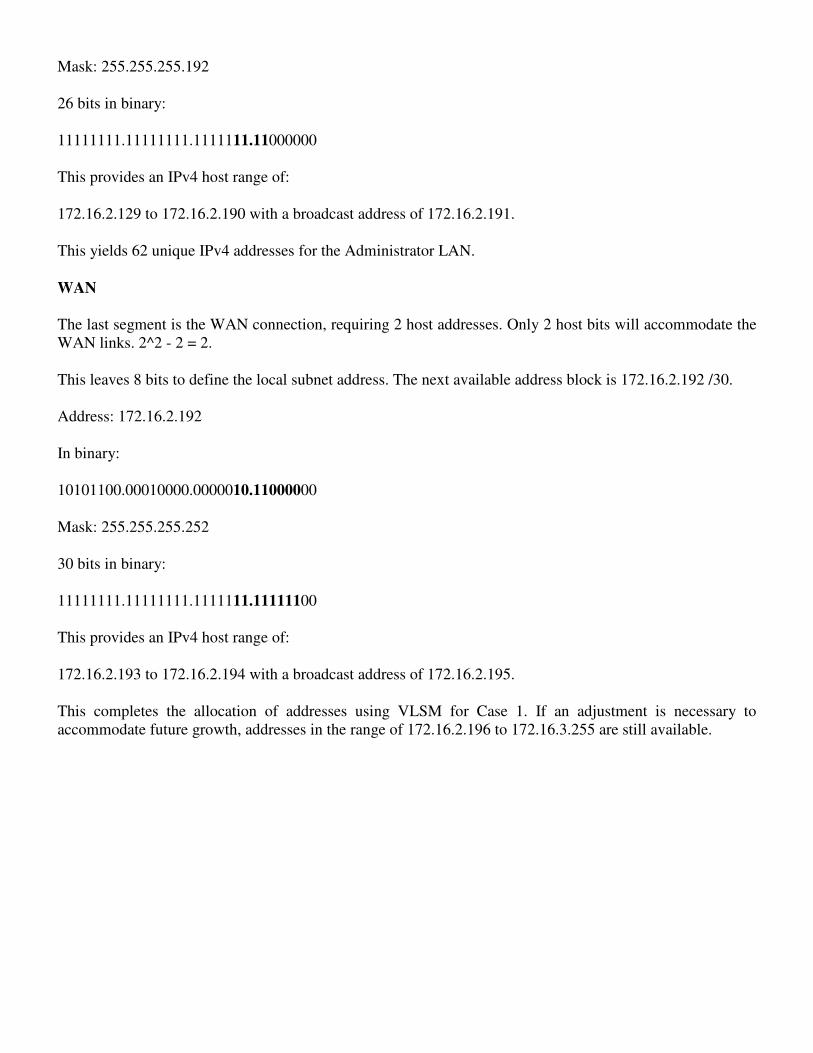
Mask: 255.255.255.192
26 bits in binary:
11111111.11111111.1111111.11000000
This provides an IPv4 host range of:
172.16.2.129 to 172.16.2.190 with a broadcast address of 172.16.2.191.
This yields 62 unique IPv4 addresses for the Administrator LAN.
WAN
The last segment is the WAN connection, requiring 2 host addresses. Only 2 host bits will accommodate the
WAN links. 2^2 - 2 = 2.
This leaves 8 bits to define the local subnet address. The next available address block is 172.16.2.192 /30.
Address: 172.16.2.192
In binary:
10101100.00010000.0000010.11000000
Mask: 255.255.255.252
30 bits in binary:
11111111.11111111.1111111.11111100
This provides an IPv4 host range of:
172.16.2.193 to 172.16.2.194 with a broadcast address of 172.16.2.195.
This completes the allocation of addresses using VLSM for Case 1. If an adjustment is necessary to
accommodate future growth, addresses in the range of 172.16.2.196 to 172.16.3.255 are still available.

Calculating Addresses: Case 2
In Case 2, the challenge is to subnet this internetwork while limiting the number of wasted hosts and subnets.
The figure shows 5 different subnets, each with different host requirements. The given IP address is
192.168.1.0/24.
The host requirements are:
• NetworkA - 14 hosts
• NetworkB - 28 hosts
• NetworkC - 2 hosts
• NetworkD - 7 hosts
• NetworkE - 28 hosts
As we did with Case 1, we begin the process by subnetting for the largest host requirement first. In this case,
the largest requirements are for NetworkB and NetworkE, each with 28 hosts.
We apply the formula: usable hosts = 2^n- 2
. For networks B and E, 5 bits are borrowed from the host portion
and the calculation is 2^5 = 32 - 2. Only 30 usable host addresses are available due to the 2 reserved
addresses. Borrowing 5 bits meets the requirement but gives little room for growth.
So you may consider borrowing 3 bits for subnets leaving 5 bits for the hosts. This allows 8 subnets with 30
hosts each.
We allocate addresses for networks B and E first:

Network B will use Subnet 0: 192.168.1.0/27
host address range 1 to 30
Network E will use Subnet 1: 192.168.1.32/27
host address range 33 to 62
The next largest host requirement is NetworkA, followed by NetworkD.
Borrowing another bit and subnetting the network address 192.168.1.64 yields a host range of:
Network A will use Subnet 0: 192.168.1.64/28
host address range 65 to 78
Network D will use Subnet 1: 192.168.1.80/28
host address range 81 to 94
This allocation supports 14 hosts on each subnet and satisfies the requirement.
Network C has only two hosts. Two bits are borrowed to meet this requirement.
Starting from 192.168.1.96 and borrowing 2 more bits results in subnet 192.168.1.96/30.
Network C will use Subnet 1: 192.168.1.96/30
host address range 97 to 98
In Case 2, we have met all requirements without wasting many potential subnets and available addresses.
In this case, bits were borrowed from addresses that had already been subnetted. As you will recall from a
previous section, this method is known as Variable Length Subnet Masking, or VLSM.

Device Interconnections
Device Interfaces
It is important to understand that Cisco devices, routers, and switches have several types of interfaces
associated with them. You have worked with these interfaces in the labs. These interfaces, also commonly
called ports, are where cables are connected to the device. See the figure for some example interfaces.
LAN Interfaces - Ethernet
The Ethernet interface is used for connecting cables that terminate with LAN devices such as computers and
switches. This interface can also be used to connect routers to each other. This use will be covered in more
detail in future courses. Several conventions for naming Ethernet interfaces are popular, including AUI
(older Cisco devices using a transceiver), Ethernet, FastEthernet and Fa 0/0. The name used depends on the
type and model of the device.
WAN Interfaces - Serial
Serial WAN interfaces are used for connecting WAN devices to the CSU/DSU. A CSU/DSU is a device
used to make the physical connection between data networks and WAN provider's circuits. Serial interfaces
between routers will also be used in our labs as part of various courses. For lab purposes, we will make a
back-to-back connection between two routers using serial cables, and set a clock rate on one of the
interfaces. You may also need to configure other Data Link and Physical layer parameters on a router. To
establish communication with a router via a console on a remote WAN, a WAN interface is assigned a Layer
3 address (IPv4 address).

Console Interface
The console interface is the primary interface for initial configuration of a Cisco router or switch. It is also an
important means of troubleshooting. It is important to note that with physical access to the router's console
interface, an unauthorized person can interrupt or compromise network traffic. Physical security of network
devices is extremely important.
Auxiliary (AUX) Interface
This interface is used for remote management of the router. Typically, a modem is connected to the AUX
interface for dial-in access. From a security standpoint, enabling the option to connect remotely to a network
device carries with it the responsibility of maintaining vigilant device management.
Making the Device Management Connection
Typically, networking devices do not have their own displays, keyboards, or input devices such as trackballs
and mice. Accessing a network device for configuration, verification, or troubleshooting is made via a
connection between the device and a computer. To enable this connection, the computer runs a program
called a terminal emulator. A terminal emulator is a software program that allows one computer to access the
functions on another device. It allows a person to use the display and keyboard on one computer to operate
another device, as if the keyboard and display were directly connected to the other device. The cable
connection between the computer running the terminal emulation program and the device is often made via
the serial interface. To connect to a router or switch for device management using terminal emulation, follow
these steps:
Step 1:
Connect a computer to the console port using the console cable supplied by Cisco. The console cable,
supplied with each router and switch, has a DB-9 connector on one end and an RJ-45 connector on the other
end. (Older Cisco devices came supplied with an RJ-45 to DB-9 adapter. This adapter is used with a rollover
cable that has an RJ-45 connector at each end.) The connection to the console is made by plugging the DB-9
connector into an available EIA/TIA 232 serial port on the computer. It is important to remember that if there
is more than one serial port, note which port number is being used for the console connection. Once the serial

connection to the computer is made, connect the RJ-45 end of the cable directly into the console interface on
the router. Many newer computers do not have an EIA/TIA 232 serial interface. If your computer has only a
USB interface, use a USB-to-serial conversion cable to access the console port. Connect the conversion cable
to a USB port on the computer and then connect the console cable or RJ-45 to DB-9 adapter to this cable.
Step 2:
With the devices directly connected via cable, configure a terminal emulator with the proper settings. The
exact instructions for configuring a terminal emulator will depend on the particular emulator. For the purpose
of this course, we will usually use HyperTerminal because most varieties of Windows have it. This program
can be found under All Programs > Accessories > Communications. Select HyperTerminal. Open
HyperTerminal, confirm the chosen serial port number, and then configure the port with these settings:
• Bits per second: 9600 bps
• Data bits: 8
• Parity: None
• Stop bits: 1
• Flow control: None
Log in to the router using the terminal emulator software. If all settings and cable connections are done
properly, you can access the router by pressing the Enter key on the keyboard. During the lab, you will have
the opportunity to use several types of terminal emulators. Each one may be slightly different in appearance,
but their uses are the same.