Embed Size (px)
Citation preview
�
ELECTRIC FULL SIZE COMPUTERIZED
CONVECTION OVENECOF-C
Installation and Operation
Instructions2M-W490 Rev. C 4/13/12
ECOF-CIL1528
�
These symbols are intended to alert the user to the presence ofimportant operating and maintenance instructions in the manualaccompanying the appliance.
FOR YOUR SAFTEYDO NOT STORE OR USE GASOLINE OR OTHER FLAMMABLE VAPORS AND LIQUIDS IN
THE VICINTIY OF THIS OR ANY OTHER APPLIANCE.
POST IN PROMINENT LOCATIONINSTRUCTIONS TO BE FOLLOWED IN THE EVENT USER SMELLS GAS. THIS
INFORMATION SHALL BE OBTAINED BY CONSULTING YOUR LOCAL GAS SUPPLIER. AS A MINIMUM, TURN OFF THE GAS AND CALL YOUR GAS COMPANY AND YOUR AUTHORIZED SERVICE AGENT. EVACUATE ALL PERSONNEL FROM THE AREA.
WARNINGIMPROPER INSTALLATION, ADJUSTMENT, ALTERATION, SERVICE OR MAINTENANCE
CAN CAUSE PROPERTY DAMAGE, INJURY OR DEATH. READ THE INSTALLATION, OPERATION & MAINTENANCE INSTRUCTIONS THOROUGHLY BEFORE INSTALLING OR
SERVICING THIS EQUIPMENT. WARNING
RISK OF FIRE OR ELECTRIC SHOCKDO NOT OPEN
WARNING, TO REDUCE THE RISK OF ELECTRICAL SHOCK, DO NOT REMOVE CONTROL PANEL. NO USER-SERVICABLE PARTS INSIDE. REPAIRS SHOULD BE DONE BY AUTHORIZED SERVICE PERSONNEL ONLY.
NOTICEUsing any part other than genuine Lang factory supplied parts relieves the manufacturer of allliability.Lang reserves the right to change specifications and product design without notice. Such revisions do not entitle the buyer to corresponding changes, improvements, additions orreplacements for previously purchased equipment.Due to periodic changes in designs, methods, procedures, policies and regulations,the specifications contained in this sheet are subject to change without notice. While Lang exercises good faith efforts to provide information that is accurate, we are not responsible for errors or omissions in information provided or conclusions reached as aresult of using the specifications. By using the information provided, the user assumes all risks in connection with such use.
MAINTENANCE AND REPAIRSContact your local dealer for service or required maintenance. Please record the model number, serialnumber, voltage and purchase & Installation Information in the area below and have it ready when you call to ensure a faster service.
SAFETY SYMBOL
Model No.:
Serial No.:
Voltage:
�-Phase or 3 Phase:
Purchased From:
Location:
Purchase Date:
Installed Date:
3
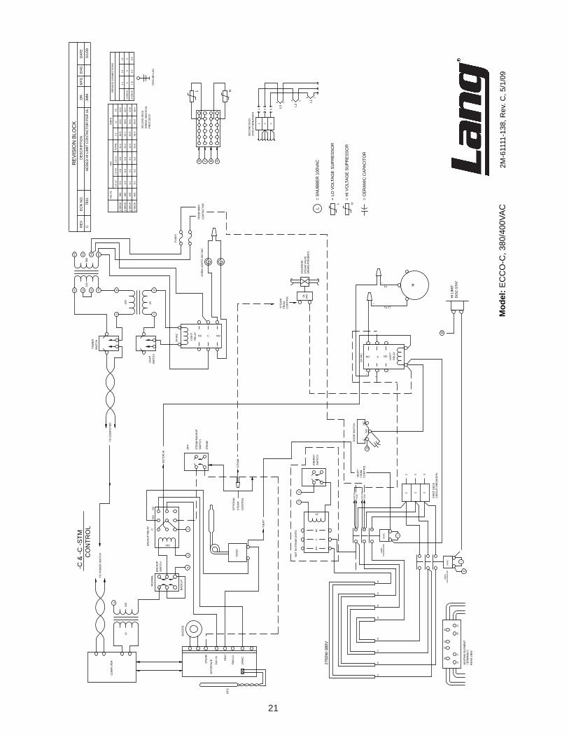
TABLE OF CONTENTSSpecifications . . . . . . . . . . . . . . . . . . . . . . . . . . . . . 4EquipmentDescription . . . . . . . . . . . . . . . . . . . . . . . . 5Unpacking. . . . . . . . . . . . . . . . . . . . . . . . . . . . . . . 6Installation LegInstallation . . . . . . . . . . . . . . . . . . . . . . . . . . 7 LegPadAdapterInstallation . . . . . . . . . . . . . . . . . . . 8 StackingtheOven. . . . . . . . . . . . . . . . . . . . . . . . . 9 Ventilation&Clearence. . . . . . . . . . . . . . . . . . . . . .�0 ElectricalConnection. . . . . . . . . . . . . . . . . . . . . . . �� OvenVoltage. . . . . . . . . . . . . . . . . . . . . . . . . . . ��InitialStart-Up Pre-PowerOn. . . . . . . . . . . . . . . . . . . . . . . . . . .�� PowerOn . . . . . . . . . . . . . . . . . . . . . . . . . . . . .��GeneralOperation&Programming ControlPanel. . . . . . . . . . . . . . . . . . . . . . . . . . . �3 StatusDisplay. . . . . . . . . . . . . . . . . . . . . . . . . . .�4 ControlPanelButton . . . . . . . . . . . . . . . . . . . . . . . �4 Hints&Suggestions. . . . . . . . . . . . . . . . . . . . . . . .�5 Loading. . . . . . . . . . . . . . . . . . . . . . . . . . . . . . �5Maintenance Cleaning. . . . . . . . . . . . . . . . . . . . . . . . . . . . . .�6Troubleshooting Symptoms/PossibleCauses/Test. . . . . . . . . . . . . . . .�7WiringDiagram �08/�40VAC. . . . . . . . . . . . . . . . . . . . . . . . . . . .�8 480V. . . . . . . . . . . . . . . . . . . . . . . . . . . . . . . �9 ��0/�40/380/4�5,3-Phase,4-Wire,50-60Hz. . . . . . . . . . .�0 380/400V,3-Phase,3-Wire,50Hz. . . . . . . . . . . . . . . . ��ExplodedView&PartsList . . . . . . . . . . . . . . . . . . . . . ��-3�
PROBLEMS, QUESTIONS or CONCERNS
Before you proceed consult you authorized Lang service agent directoryor
Call the Lang Technical Service & Parts Department at 314-678-6315.
NOTICE: Service on this or any other Lang appliance must be performed by qualified per-sonnel only. Consult your Lang Authorized Service Agent Directory. You can call our tech service number 314-678-6315 or visit our website www.langworld.com for the service agent nearest you.
4
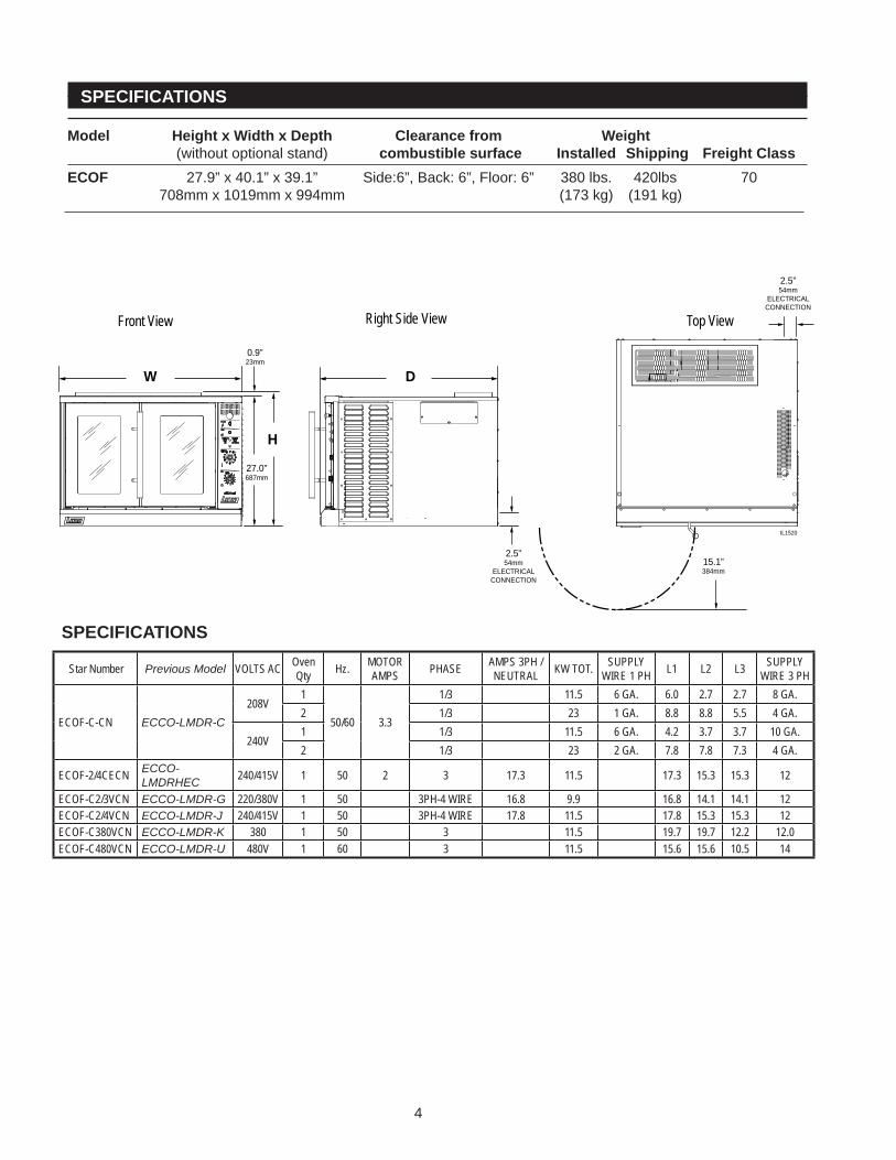
SPECIFICATIONS Model Height x Width x Depth Clearance from Weight (withoutoptionalstand) combustible surface Installed Shipping Freight ClassECOF �7.9”x40.�”x39.�” Side:6”,Back:6”,Floor:6” 380lbs. 4�0lbs 70 708mmx�0�9mmx994mm (�73kg) (�9�kg)
15.1”384mm
2.5”54mm
ELECTRICALCONNECTION
2.5”54mm
ELECTRICALCONNECTION
27.0”687mm
0.9”23mm
IL1520
Front View Right Side View Top View
W
H
D
SPECIFICATIONS
Star Number Previous Model VOLTS AC Oven Qty Hz. MOTOR
AMPS PHASE AMPS 3PH / NEUTRAL KW TOT. SUPPLY
WIRE 1 PH L1 L2 L3 SUPPLY WIRE 3 PH
ECOF-C-CN ECCO-LMDR-C208V
1
50/60 3.3
1/3 11.5 6 GA. 6.0 2.7 2.7 8 GA.2 1/3 23 1 GA. 8.8 8.8 5.5 4 GA.
240V1 1/3 11.5 6 GA. 4.2 3.7 3.7 10 GA.2 1/3 23 2 GA. 7.8 7.8 7.3 4 GA.
ECOF-2/4CECN ECCO-LMDRHEC 240/415V 1 50 2 3 17.3 11.5 17.3 15.3 15.3 12
ECOF-C2/3VCN ECCO-LMDR-G 220/380V 1 50 3PH-4 WIRE 16.8 9.9 16.8 14.1 14.1 12ECOF-C2/4VCN ECCO-LMDR-J 240/415V 1 50 3PH-4 WIRE 17.8 11.5 17.8 15.3 15.3 12ECOF-C380VCN ECCO-LMDR-K 380 1 50 3 11.5 19.7 19.7 12.2 12.0ECOF-C480VCN ECCO-LMDR-U 480V 1 60 3 11.5 15.6 15.6 10.5 14
5
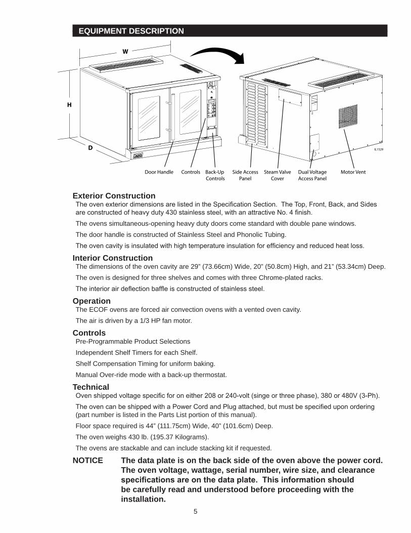
EQUIPMENT DESCRIPTION
Exterior ConstructionThe oven exterior dimensions are listed in the Specification Section. The Top, Front, Back, and Sides are constructed of heavy duty 430 stainless steel, with an attractive No. 4 finish.Theovenssimultaneous-openingheavydutydoorscomestandardwithdoublepanewindows.ThedoorhandleisconstructedofStainlessSteelandPhonolicTubing.The oven cavity is insulated with high temperature insulation for efficiency and reduced heat loss.
Interior ConstructionThedimensionsoftheovencavityare�9”(73.66cm)Wide,�0”(50.8cm)High,and��”(53.34cm)Deep.TheovenisdesignedforthreeshelvesandcomeswiththreeChrome-platedracks.The interior air deflection baffle is constructed of stainless steel.
OperationTheECOFovensareforcedairconvectionovenswithaventedovencavity.Theairisdrivenbya�/3HPfanmotor.
ControlsPre-ProgrammableProductSelectionsIndependentShelfTimersforeachShelf.ShelfCompensationTimingforuniformbaking.ManualOver-ridemodewithaback-upthermostat.
TechnicalOven shipped voltage specific for on either 208 or 240-volt (singe or three phase), 380 or 480V (3-Ph).The oven can be shipped with a Power Cord and Plug attached, but must be specified upon ordering (partnumberislistedinthePartsListportionofthismanual).Floorspacerequiredis44”(���.75cm)Wide,40”(�0�.6cm)Deep.Theovenweighs430lb.(�95.37Kilograms).Theovensarestackableandcanincludestackingkitifrequested.
NOTICE The data plate is on the back side of the oven above the power cord. The oven voltage, wattage, serial number, wire size, and clearance specifications are on the data plate. This information should be carefully read and understood before proceeding with the installation.
Steam ValveCover
Dual VoltageAccess Panel
Motor VentSide AccessPanel
Door Handle Back-Up Controls
Controls
IL1529
H
W
D
6
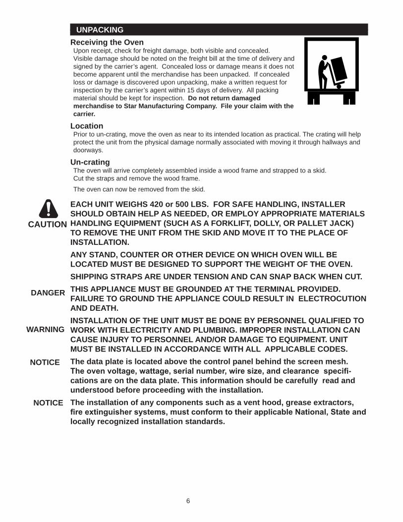
UNPACKINGReceiving the OvenUponreceipt,checkforfreightdamage,bothvisibleandconcealed.Visibledamageshouldbenotedonthefreightbillatthetimeofdeliveryandsignedbythecarrier’sagent.Concealedlossordamagemeansitdoesnotbecomeapparentuntilthemerchandisehasbeenunpacked.Ifconcealedlossordamageisdiscovereduponunpacking,makeawrittenrequestforinspectionbythecarrier’sagentwithin�5daysofdelivery.Allpackingmaterialshouldbekeptforinspection.Do not return damaged merchandise to Star Manufacturing Company. File your claim with the carrier.
LocationPriortoun-crating,movetheovenasneartoitsintendedlocationaspractical.Thecratingwillhelpprotecttheunitfromthephysicaldamagenormallyassociatedwithmovingitthroughhallwaysanddoorways.
Un-cratingTheovenwillarrivecompletelyassembledinsideawoodframeandstrappedtoaskid.Cutthestrapsandremovethewoodframe.Theovencannowberemovedfromtheskid.
EACH UNIT WEIGHS 420 or 500 LBS. FOR SAFE HANDLING, INSTALLER SHOULD OBTAIN HELP AS NEEDED, OR EMPLOY APPROPRIATE MATERIALS HANDLING EQUIPMENT (SUCH AS A FORKLIFT, DOLLY, OR PALLET JACK) TO REMOVE THE UNIT FROM THE SKID AND MOVE IT TO THE PLACE OF INSTALLATION.ANY STAND, COUNTER OR OTHER DEVICE ON WHICH OVEN WILL BE LOCATED MUST BE DESIGNED TO SUPPORT THE WEIGHT OF THE OVEN.SHIPPING STRAPS ARE UNDER TENSION AND CAN SNAP BACK WHEN CUT.THIS APPLIANCE MUST BE GROUNDED AT THE TERMINAL PROVIDED. FAILURE TO GROUND THE APPLIANCE COULD RESULT IN ELECTROCUTION AND DEATH.INSTALLATION OF THE UNIT MUST BE DONE BY PERSONNEL QUALIFIED TO WORK WITH ELECTRICITY AND PLUMBING. IMPROPER INSTALLATION CAN CAUSE INJURY TO PERSONNEL AND/OR DAMAGE TO EQUIPMENT. UNIT MUST BE INSTALLED IN ACCORDANCE WITH ALL APPLICABLE CODES.The data plate is located above the control panel behind the screen mesh. The oven voltage, wattage, serial number, wire size, and clearance specifi-cations are on the data plate. This information should be carefully read and understood before proceeding with the installation.The installation of any components such as a vent hood, grease extractors, fire extinguisher systems, must conform to their applicable National, State and locally recognized installation standards.
CAUTION
DANGER
WARNING
NOTICE
NOTICE
7
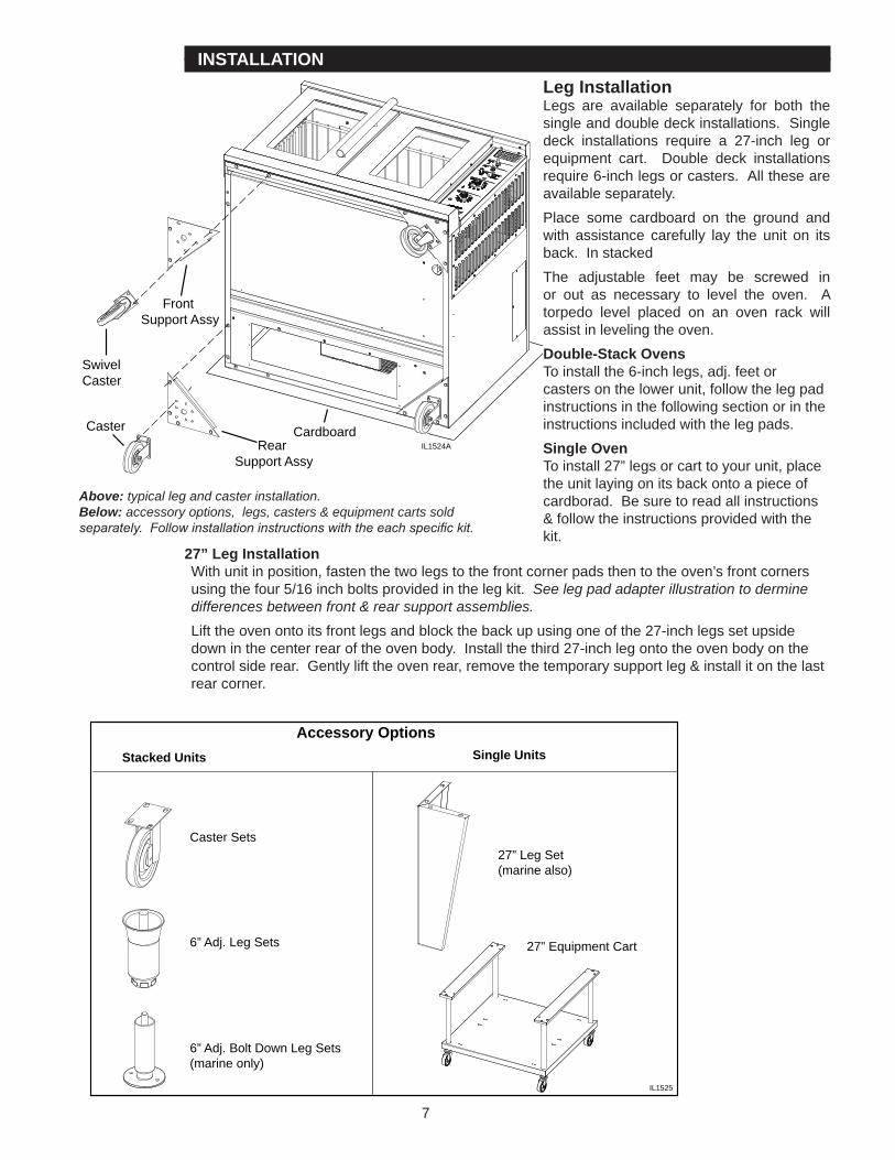
INSTALLATIONLeg InstallationLegs are available separately for both thesingleanddoubledeckinstallations.Singledeck installations require a �7-inch leg orequipment cart. Double deck installationsrequire6-inchlegsorcasters.Alltheseareavailableseparately.Place some cardboard on the ground andwith assistance carefully lay the unit on itsback.InstackedThe adjustable feet may be screwed inor out as necessary to level the oven. Atorpedo level placed on an oven rack willassistinlevelingtheoven.Double-Stack Ovens Toinstallthe6-inchlegs,adj.feetorcastersonthelowerunit,followthelegpadinstructionsinthefollowingsectionorintheinstructionsincludedwiththelegpads.Single OvenToinstall�7”legsorcarttoyourunit,placetheunitlayingonitsbackontoapieceofcardborad.Besuretoreadallinstructions&followtheinstructionsprovidedwiththekit.
27” Leg InstallationWithunitinposition,fastenthetwolegstothefrontcornerpadsthentotheoven’sfrontcornersusingthefour5/�6inchboltsprovidedinthelegkit.See leg pad adapter illustration to dermine differences between front & rear support assemblies. Lifttheovenontoitsfrontlegsandblockthebackupusingoneofthe�7-inchlegssetupsidedowninthecenterrearoftheovenbody.Installthethird�7-inchlegontotheovenbodyonthecontrolsiderear.Gentlylifttheovenrear,removethetemporarysupportleg&installitonthelastrearcorner.
RearSupport Assy
FrontSupport Assy
SwivelCaster
Caster CardboardIL1524A
Above: typical leg and caster installation. Below: accessory options, legs, casters & equipment carts sold separately. Follow installation instructions with the each specific kit.
Stacked Units
Caster Sets27” Leg Set(marine also)
27” Equipment Cart6” Adj. Leg Sets
6” Adj. Bolt Down Leg Sets(marine only)
Accessory OptionsSingle Units
IL1525
8
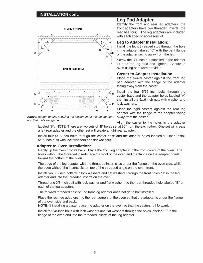
INSTALLATION cont.Leg Pad AdapterIdentify the front and rear leg adapters (thefrontadaptershave two threaded inserts, therearhasfour).Thelegadaptersareincludedwith each specific accessory kit.
Leg to Adapter Installation:Installtheleg’sthreadedstudthroughtheholein the adapter labeled “C” with the bent flange oftheadapterfacingawayfromtheleg.Screwthe3/4-inchnutsuppliedintheadapterkit onto the leg stud and tighten. Secure toovenusinghardwareprovided.
Caster to Adapter Installation:Place the swivel caster against the front legpad adapter with the flange of the adapter facingawayfromthecaster.Install the four 5/�6 inch bolts through thecasterbaseandtheadapterholeslabeled“A”theninstallthe5/�6inchnutswithwasherandlockwashers.Place the rigid casters against the rear legadapter with the flange of the adapter facing awayfromthecaster.Align the caster to the holes in the adapter
labeled“B”.NOTE:Therearetwosetsof“B”holessetat90°fromtheeachother.Onesetwillcreatealeftrearadapterandtheothersetwillcreatearightrearadapter.Install four 5/�6-inchbolts through the caster baseand theadapter holes labeled “B” then install5/16-inch nuts with lock washers and flat washers.
Adapter to Oven Installation:Gentlytiptheovenontoitsback.Placethefrontlegadapterintothefrontcorersoftheoven.Theholes without the threaded inserts face the front of the oven and the flange on the adapter points towardthebottomoftheoven.The edge of the leg adapter with the threaded insert slips under the flange on the oven side, while theedgewithouttheinsertssitsontopofthethreadedangleontheovenfront.Install two 3/8-inch bolts with lock washers and flat washers through the front holes “D” in the leg adapterandintothethreadedinsertsontheoven.Thread one 3/8-inch bolt with lock washer and flat washer into the rear threaded hole labeled “E” on eachofthelegadapters.Theforwardthreadedholeonthefrontlegadapterdoesnotgetaboltinstalled.Place the rear leg adapters into the rear corners of the oven so that the adapter is under the flange oftheovensideandback.NOTE:Ifinstallingacasterplacetheadapterontheovensothatthecastersrollforward.Install for 3/8-inch bolts with lock washers and flat washers through the holes labeled “E” in the flange of the oven and into the threaded inserts of the leg adapter.
D
E
E
E
E E E E
E
E
E
A A
A
B
B
B
B
AC
D D D
C
C C
OVEN BOTTOM
OVEN FRONT
IL1523
Above: Bottom on unit showing the placement of the leg adapters and their hole assignment.
9
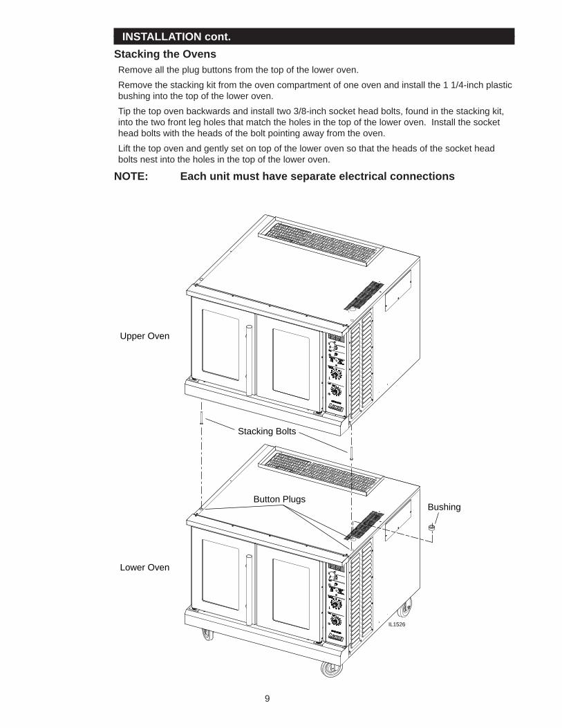
INSTALLATION cont.Stacking the OvensRemovealltheplugbuttonsfromthetopoftheloweroven.Removethestackingkitfromtheovencompartmentofoneovenandinstallthe��/4-inchplasticbushingintothetopoftheloweroven.Tipthetopovenbackwardsandinstalltwo3/8-inchsocketheadbolts,foundinthestackingkit,intothetwofrontlegholesthatmatchtheholesinthetopoftheloweroven.Installthesocketheadboltswiththeheadsoftheboltpointingawayfromtheoven.Liftthetopovenandgentlysetontopofthelowerovensothattheheadsofthesocketheadboltsnestintotheholesinthetopoftheloweroven.
NOTE: Each unit must have separate electrical connections
Button PlugsBushing
Stacking Bolts
Upper Oven
Lower Oven
IL1526
�0
INSTALLATION continuedVentilation and ClearancesStandardminimumclearancefromcombustibleconstructionisasfollows.
4”fromside4”fromback6” from floor
•Theseovensmaybesetdirectly,withoutlegs,onacurbedbaseornon-combustible floor.•Iftheovenissetwithoutlegsonanon-combustible floor or a curbed base, maintain a 4-inch back
clearance.•Iftheovenissetdirectlyagainstanon-combustiblebackwall,maintaina6-inchclearancetothe
floor.•Do notinstalltheovencloserthan4inchesfromanotherovenontherighthandside(controlpanel
side).•Do not installtheovencloserthan��inchesfromanuncontrolledheatsource(charbroileretc.)on
therightside.• Keep the area free & clear of combustible material, and do not obstruct the flow of combustion or
ventilationair.• The installation of any components such as a vent hood, grease extractors, and/or fire extinguisher
systems,mustconformtotheapplicablenationallyrecognizedinstallationstandards.
NOTICE The installation of any components such as a vent hood, grease extractors, fire extinguisher systems, must conform to their applicable National, State and locally recognized installation standards.
��
WARNING
WARNING
INSTALLATION continuedElectrical ConnectionTheelectricalconnectionmustbemadeinaccordancewithlocalcodesorintheabsenceoflocalcodeswithNFPANo.70latestedition(inCanadause:CSASTD.C��.�).Theelectricalserviceentranceisprovidedbya��/4-inchknockoutinthebottomrightfrontcornerofeachoven,orattheovenbackdirectlybehindthecontrolcompartment.Groundinglugsareprovidedatboththefrontandrearserviceentrances.The�08/�40-voltovenisadualvoltageovenandisshippedfromthefactoryas�08volt.Theovenmust be field converted to operate on a 240-volt power supply. To convert the oven to 240 volt, removethetwoscrewssecuringtheaccesscoveronthebackoftheunit,andremove.Thereyouwill find a switch, move it to the position matching you electrical service (208V or 240V). Earlier modelsrequiredyoutoremovethejumperwirelocatedunderthecontrolcompartmentbehindthebottomtrimpiece.With380V,440V&480-voltinstallationschecktobesurethatthemotorrotatesinaclockwisedirectionasviewedfromthefrontoftheoven.Toreversethemotorrotation,switchanytwoincomingpowersupplyleadsandrechecktherotation.Supplywiresizemustbelargeenoughtocarrytheamperageloadforthenumberofovensbeinginstalled. Wire size information can be found on the oven DATA PLATE or in the specifications sectiononpage4.�08/�40Vovenscanbeinstalledonbothsingleandthree-phasesuppliesandisshippedfromthefactoryforthree-phase.Tophasetheoventomatchthepowersupply,followthechartsonthewiringdiagramlocatedatthebackofthemanual.CertainunitsareprovidedwithorcanbepurchasedwithaCord&Plugkit(Part number 2E-60101-67).Thiskitincludesa48”cordwithaNEMAL�5-50Pplugandisfor�08/�40VunitsONLY(480VapplicationsusePS-60�0�-68).Instackedsituationseachunitsneedstohaveseparatecord&plugassemblies,contactLangParts&Serviceat�-800-807-9054toorder.
Oven VoltageTheLangModelECOFovenscanbeoperatedon�08,�40-volt(singleorthreephase),or380/440/480V(threephaseonly)source.TheAmpdraw,KWrating,andphasingcanbefoundinspecification section of this manual.
THIS APPLIANCE MUST BE GROUNDED AT THE TERMINAL PROVIDED. FAILURE TO GROUND THE APPLIANCE COULD RESULT IN ELECTROCUTION AND DEATH.INSTALLATION OF THE UNIT MUST BE DONE BY PERSONNEL QUALIFIED TO WORK WITH ELECTRICITY AND PLUMBING. IMPROPER INSTALLATION CAN CAUSE INJURY TO PERSONNEL AND/OR DAMAGE TO EQUIPMENT. UNIT MUST BE INSTALLED IN ACCORDANCE WITH ALL APPLICABLE CODES.
��
INITIAL START UPPre-Power OnAftertheovenisinstalledandconnectedtopower,priortoturningon,verifythefollowing:• Thedoorsopenandclosefreely.• Allracksareintheovencorrectly.• Allpackingmaterialshavebeenremovedfromtheinsideoftheoven.
Power OnOnceovenhasbeenturnedonverifythattheblowerwheelisspinningfreelyinaclockwisepositionandthattheelementsareheatingproperly.Theovenwillautomaticallysay“preht”andbeginheating.Oncetheovenhasreachedpre-programmedtempdisplaywillread“ready”.Productmaynowbeplacedintheoven.
NOTICE During the first few hours of operation you may notice a small amount of smoke coming off the oven, and a faint odor from the smoke. This is normal for a new oven and will disappear after the first few hours of use.INITIAL START UP
�3
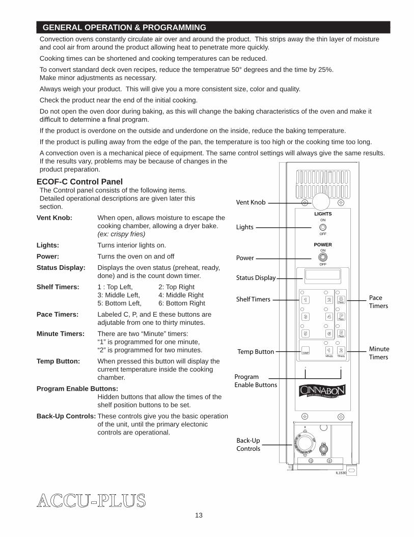
GENERAL OPERATION & PROGRAMMINGConvectionovensconstantlycirculateairoverandaroundtheproduct.Thisstripsawaythethinlayerofmoistureandcoolairfromaroundtheproductallowingheattopenetratemorequickly.Cookingtimescanbeshortenedandcookingtemperaturescanbereduced.Toconvertstandarddeckovenrecipes,reducethetemperatrue50°degreesandthetimeby�5%.Makeminoradjustmentsasnecessary.Alwaysweighyourproduct.Thiswillgiveyouamoreconsistentsize,colorandquality.Checktheproductneartheendoftheinitialcooking.Donotopentheovendoorduringbaking,asthiswillchangethebakingcharacteristicsoftheovenandmakeitdifficult to determine a final program.Iftheproductisoverdoneontheoutsideandunderdoneontheinside,reducethebakingtemperature.Iftheproductispullingawayfromtheedgeofthepan,thetemperatureistoohighorthecookingtimetoolong.Aconvectionovenisamechanicalpieceofequipment.Thesamecontrolsettingswillalwaysgivethesameresults.Iftheresultsvary,problemsmaybebecauseofchangesintheproductpreparation.
ECOF-C Control PanelTheControlpanelconsistsofthefollowingitems.Detailedoperationaldescriptionsaregivenlaterthissection.
Vent Knob: Whenopen,allowsmoisturetoescapethecookingchamber,allowingadryerbake.(ex: crispy fries)
Lights: Turnsinteriorlightson.Power: TurnstheovenonandoffStatus Display: Displaystheovenstatus(preheat,ready,
done)andisthecountdowntimer.Shelf Timers: �:TopLeft, �:TopRight
3:MiddleLeft, 4:MiddleRight5:BottomLeft, 6:BottomRight
Pace Timers: LabeledC,P,andEthesebuttonsareadjutablefromonetothirtyminutes.
Minute Timers: Therearetwo“Minute”timers:“�”isprogrammedforoneminute,“�”isprogrammedfortwominutes.
Temp Button: Whenpressedthisbuttonwilldisplaythecurrenttemperatureinsidethecookingchamber.
Program Enable Buttons:Hiddenbuttonsthatallowthetimesoftheshelfpositionbuttonstobeset.
Back-Up Controls:Thesecontrolsgiveyouthebasicoperationoftheunit,untiltheprimaryelectoniccontrolsareoperational.
LIGHTSON
OFF
ON
OFF
POWER
Vent Knob
Shelf Timers
Status Display
Temp Button
Program Enable Buttons
Back-Up Controls
Minute Timers
Pace Timers
Lights
Power
IL1530
�4
General Operation & Programming cont.Status DisplayTheStatusDisplayinformstheoperatoroftheoven’scondition.Preht: StandsforPREHEAT.Theovenisonandadjustingtothepreprogrammedtemperature
(350°F).Ready: Theovenhasreachedthepresettemperatureandiswaitingforproducttobeloadedinto
theoven.Cool: Theoven’sinternaltemperatureisbelowwhatisprogrammed.Hot: Theoven’sinternaltemperatureisabovewhatisprogrammed.Done: The time has expired for that program and the product is finished.Help: Thereisafaultinthecontrolsystem;thecomputerwillnotoperateuntilserviceisperformed.
Control Panel ButtonsShelf Buttons: Placetheproductintotheovenononeofthesixshelfpositions.
Close the oven doors. Press the shelf position button thatcorrespondstotheshelfpositiononcefor“C”product,twicefor“P”product,threetimesfor“E”product,orfourtimesforoff.Abeeperwillsoundoncetheproductisdoneand“done”willbedisplayed. Press the flashing shelf to cancel the beeper.
Minute and Pace Timers:The“�”buttonispresettooneminute,the“�”buttonispresettotwominutes,andthe“Pace“buttonsareadjustablefromonetothirtyminutes.Pressthebuttononcetostartthetimer.Thedisplaywillreadouttheprogrammedtimeandthenreverttotheprevious read out.The timers will countdown internally.Timeremainingcanberecalledbypressingthebuttonagain.
Canceling a timer: Any timer can be cancelled at any time. Press and hold thetimertobecancelleduntil“cancl”appearsinthedisplay.
ProgrammingPace Timers: Thepacetimerscanbesetatanytime.Pressandholdthe“PACE”button
forthreeseconds.Thedisplaywillreadoutthesettimethenbegintoflash. Press the “1” minute button to increase the time, or the “2” minute buttontodecreasethetime.Oncethecorrectedtimeisset,pressandholdthe“PACE”buttonforthreesecondstoexittheprogrammingmode.
Program Enable Buttons: Thecontrolcannotbeputintotheprogrammingmodeifanyofthetimersarerunning.Thetwobluedotsabovethe“CINNABON”logoaretheprogramenablebuttons.Presstheleftdotthentherightdotwithin3secondstoputthecontrolintoaprogrammingmode.Oncetheshelfpositionbuttonsareset,presstheleftdotthentherightdotwithin3secondstoexittheprogrammingmode.Therewillbenobeepersoundwhenthebuttonsarepressed.
Shelf Position Buttons: Putthecontrolintotheprogrammingmode.Presstheshelfbuttontobeadjustedoncefor“C”product,twicefor“P”product,orthreetimesfor“E” product. The display will read out “00:00” then begin to flash. Press theone-minutetimerbuttontoincreasethetime,orthetwo-minutetimerbuttontodecreasethetime.Oncethecorrecttimeissetmoveontoanothershelfpositionbuttonorexittheprogrammingmode.
�5
General Operation & Programming cont.
Hints & SuggestionsConvectionovensconstantlycirculateairoverandaroundtheproduct.Thisstripsawaythethinlayerofmoistureandcoolairfromaroundtheproductallowingheattopenetratemorequickly.Cookingtimescanbeshortenedandcookingtemperaturescanbereduced.Toconvertstandarddeckovenrecipes,reducethetemperature50degreesandthetimeby�5%.Makeminoradjustmentsasnecessary.Thelowertheoventemperaturethemoreeventhebake.Alwaysweighyourproduct.Thiswillgiveyouamoreconsistentsize,colorandquality.Checktheproductneartheendoftheinitialcookingcyclebyturningontheovenlightandlookingthroughtheovendoorwindows.Donotopentheovendoorsduringbakingasthiswillchangethebakingcharacteristicsoftheovenandmake it difficult to determine a final program.Iftheproductisoverdoneontheoutsideandunderdoneontheinside,reducethebakingtemperature.Iftheproductispullingawayfromtheedgeofthepan,thetemperatureistoohighorthecookingtimetoolong.Theconvectionisamechanicalpieceofequipment.Thesamecontrolsettingswillalwaysgivethesameresults.Iftheresultsvary,problemsmaybebecauseofproductpreparation.Openingtheventwilltoallowmosituretoescapethecookingchamberduringpartorallofthecookingprocess. This will allow a more crispy product, example: french fries, fish, crispy crusts. Close the vent fordoughproductslikecinnamonrolls,breads.Thisissomethingtoexperimentwithtodeterminewhatis best for your specific menu.
LoadingHerearesomethingstorememberwhenloadingyouroven.•Whenloadingandunloadingtheoven,stageproductsandrackssotheovendoorisopenedforthe
leastamountoftime.• Besurethatracksarelevelwithintheoven.• Bentorwarpedpanscangreatlyaffecttheevennessofthecookorbake.• Ifusingbaker’sparchment,besuretheparchmentdoesnotblowovertheproduct.Thatwillcreate
anunevenbake.• Loadeachshelfevenly.Spacesshouldbemaintainedequallybetweenthepanandovenwalls,front
andback.• Donotoverloadpan’sthiswillcreateanunevenbake.• Forbestbakingresults,loadtheovenfromthecenteroutduringrandomloading.
ALWAYS KEEP THE AREA NEAR THE APPLIANCE FREE FROM COMBUSTIBLE MATERIALS.
KEEP FLOOR IN FRONT OF EQUIPMENT CLEAN AND DRY. IF SPILLS OCCUR, CLEAN IMMEDIATELY, TO AVOID THE DANGER OF SLIPS OR FALLS.
CAUTION
�6
MAINTENANCE • Oveninteriorsshouldbewipeddowndailyandthoroughlycleanedweeklyusingwarmwaterandmilddetergent.
DO NOT use caustic cleaners.• The appliance should be thoroughly checked at six-monthly intervals by a qualified technician
(heatingunit,mechanicalstability,corrosion...)withparticularemphasisonallcontrolandsafetydevices.
CLEANING • Alwaysstartwithacoldoven.• Thestainlessexteriorcaneasilybecleanedusingstainlesssteelcleaner.• Alwaysfollowthecleanermanufacturer’sinstructionswhenusinganycleaner.• Careshouldbetakentopreventcausticcleaningcompoundsfromcomingincontactwiththefanwheel.• Theovenracks,rackslides,maybecleanedoutsidetheovencavityusingovencleaner.• UsinganyharshchemicalswillresultintheremovaloftheETCcoatingandetchingofthe
porcelainbelowit.Theoveninteriorshouldonlybecleanedusingamildsoapandanonmetalscouringpad.DO NOT use caustic cleaners.
• Alwaysapplystainlesssteelcleanerswhentheoveniscoldandrubinthedirectionofthemetal’sgrain.
KEEP WATER AND SOLUTIONS OUT OF CONTROLS. NEVER SPRAY OR HOSE CONTROL CONSOLE, ELECTRICAL CONNECTIONS, ETC.
MOST CLEANERS ARE HARMFUL TO THE SKIN, EYES, MUCOUS MEMBRANES AND CLOTHING. PRECAUTIONS SHOULD BE TAKEN TO WEAR RUBBER GLOVES, GOGGLES OR FACE SHIELD AND PROTECTIVE CLOTHING.
CAREFULLY READ THE WARNING AND FOLLOW THE DIRECTIONS ON THE LABEL OF THE CLEANER TO BE USED.
NEVER LEAVE A CHLORINE SANITIZER IN CONTACT WITH STAINLESS STEEL SURFACES LONGER THAN 10 MINUTES. LONGER CONTACT CAN CAUSE CORROSION.
WARNING
CAUTION
�7
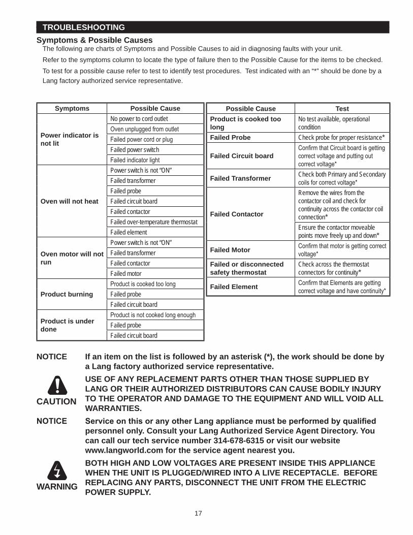
TROUBLESHOOTINGSymptoms & Possible Causes
ThefollowingarechartsofSymptomsandPossibleCausestoaidindiagnosingfaultswithyourunit.RefertothesymptomscolumntolocatethetypeoffailurethentothePossibleCausefortheitemstobechecked.Totestforapossiblecauserefertotesttoidentifytestprocedures.Testindicatedwithan“*”shouldbedonebyaLangfactoryauthorizedservicerepresentative.
Possible Cause TestProduct is cooked too long
No test available, operational condition
Failed Probe Check probe for proper resistance*
Failed Circuit boardConfirm that Circuit board is getting correct voltage and putting out correct voltage*
Failed Transformer Check both Primary and Secondary coils for correct voltage*
Failed Contactor
Remove the wires from the contactor coil and check for continuity across the contactor coil connection*Ensure the contactor moveable points move freely up and down*
Failed Motor Confirm that motor is getting correct voltage*
Failed or disconnected safety thermostat
Check across the thermostat connectors for continuity*
Failed Element Confirm that Elements are getting correct voltage and have continuity*
NOTICE If an item on the list is followed by an asterisk (*), the work should be done by a Lang factory authorized service representative.
USE OF ANY REPLACEMENT PARTS OTHER THAN THOSE SUPPLIED BY LANG OR THEIR AUTHORIZED DISTRIBUTORS CAN CAUSE BODILY INJURY TO THE OPERATOR AND DAMAGE TO THE EQUIPMENT AND WILL VOID ALL WARRANTIES.
NOTICE Service on this or any other Lang appliance must be performed by qualified personnel only. Consult your Lang Authorized Service Agent Directory. You can call our tech service number 314-678-6315 or visit our website www.langworld.com for the service agent nearest you.
BOTH HIGH AND LOW VOLTAGES ARE PRESENT INSIDE THIS APPLIANCE WHEN THE UNIT IS PLUGGED/WIRED INTO A LIVE RECEPTACLE. BEFORE REPLACING ANY PARTS, DISCONNECT THE UNIT FROM THE ELECTRIC POWER SUPPLY.
CAUTION
WARNING
Symptoms Possible Cause
Power indicator is not lit
No power to cord outletOven unplugged from outletFailed power cord or plugFailed power switchFailed indicator light
Oven will not heat
Power switch is not “ON”Failed transformerFailed probeFailed circuit boardFailed contactorFailed over-temperature thermostatFailed element
Oven motor will not run
Power switch is not “ON”Failed transformerFailed contactorFailed motor
Product burningProduct is cooked too longFailed probeFailed circuit board
Product is under done
Product is not cooked long enoughFailed probeFailed circuit board
�8
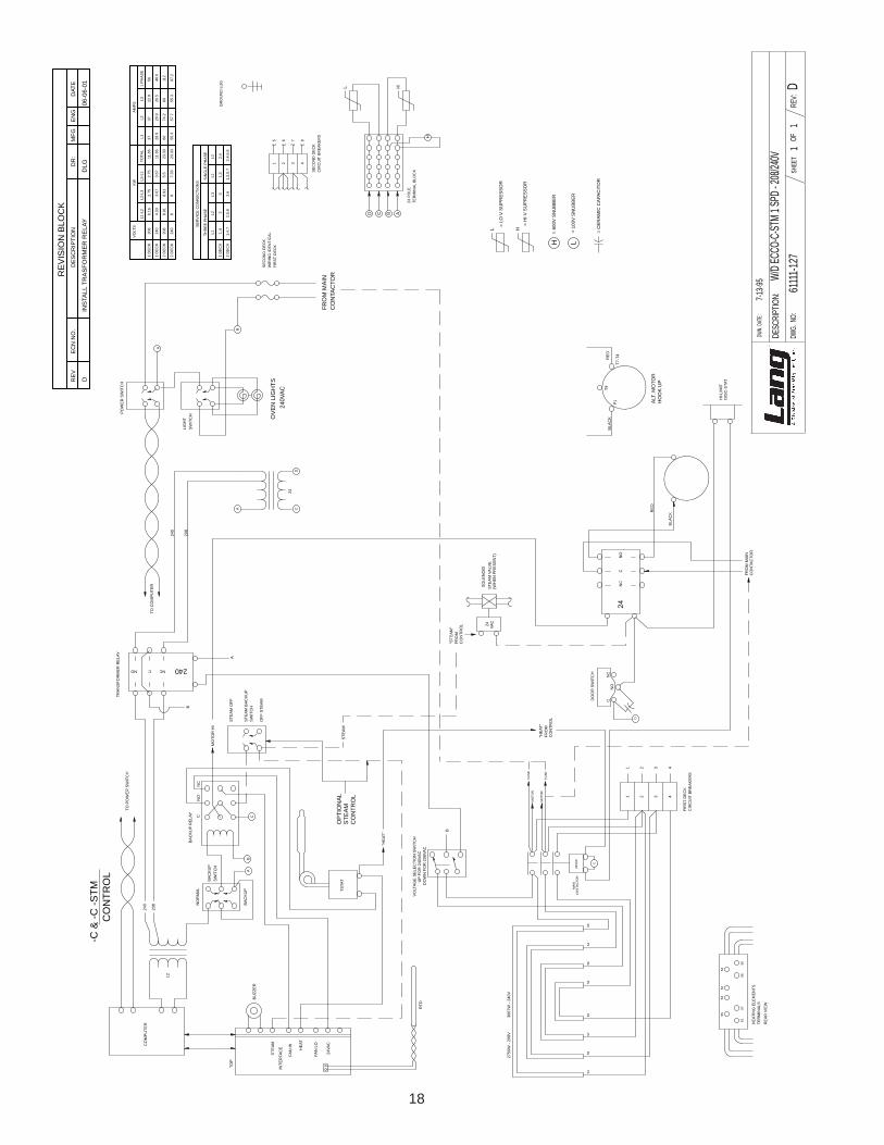
7-13-9
5
DWG.
NO:
SHEE
TOF
DWN.
DATE
:
DESC
RIPT
ION:
W/D E
CCO-
C-STM
1 SP
D - 20
8/240
V61
111-1
27RE
V:1
D1
SE
CO
ND
DE
CK
WIR
ING
IDE
NTI
CA
LFI
RS
T D
EC
K1 2 3 4
8765
CIR
CU
IT B
RE
AK
ER
SS
EC
ON
D D
EC
K
TER
MIN
AL
BLO
CK
24 P
OLE
PO
WE
R S
WIT
CH
-C &
-C -S
TMC
ON
TRO
L
BU
ZZE
R
TOP
P1
T9
T7-T
4
ALT
. MO
TOR
HO
OK
UP
24
5553
5254
5157
5650
5155
5753
5256
5450
240
STE
AM
HE
AT
FAN
LO
FAN
HI
24VA
C
INTE
RFA
CE
B
BA
CK
UP
RE
LAY
CN
ON
C
MO
TOR
HI
STE
AM
BA
CK
UP
CO
MP
UTE
R
TSTA
T
"HE
AT"
STE
AM
CO
NTR
OL
FRO
M"H
EAT
"
NO
NC
C
D
SO
LEN
OID
STE
AM
VA
LVE
(WH
EN
PR
ES
EN
T)
CO
NTR
OL
FRO
M"S
TEA
M" 24 VA
C
L
1 2 3 44321
FUS
E
FUS
E
CO
NTA
CTO
RM
AIN
24VA
C
B
LIG
HT
240V
AC
FRO
M M
AIN
D C AB
OV
EN
LIG
HTS
SW
ITC
H
DIS
C-S
TAT
HI-L
IMIT
DO
OR
SW
ITC
H
FIR
ST
DE
CK
CIR
CU
IT B
RE
AK
ER
S
TER
MIN
ALS
HE
ATIN
G E
LEM
EN
TS
RE
AR
VIE
W
BA
CK
UP
SW
ITC
H
SW
ITC
H
TO P
OW
ER
SW
ITC
H
BA
CK
UP
NO
RM
AL
STE
AM
OFF
OFF
STE
AM
TO C
OM
PU
TER
12
MO
TOR
MO
TOR
NO
NC
C24
CO
NTA
CTO
RFR
OM
MA
IN
RTD
AC
STE
AM
OP
TIO
NA
L
CO
NTR
OL
CO
NTA
CTO
R
L H
H
H
HL
L
= LO
V S
UP
RE
SS
OR
= H
I V S
UP
RE
SS
OR
= 60
0V S
NU
BB
ER
= 10
0V S
NU
BB
ER
2750
W -
208V
366
7W -
240V
RE
D
BLA
CK
= C
ER
AM
IC C
APA
CIT
OR
BLA
CK
RE
D
VO
LTA
GE
SE
LEC
TIO
N S
WIT
CH
UP
FOR
240
VAC
DO
WN
FO
R 2
08VA
C
B
208
CD
A
A
240
208
A
B
NC 240NO C
TRA
NS
FOR
ME
R R
ELA
Y
1 D
EC
K
1 D
EC
K
2 D
EC
K
2 D
EC
K
VO
LTS
L1-L
2L2
-L3
L3-L
1TO
TAL
L1L2
L31
PH
AS
E
KW
AM
PS
240
208
240
208
88.91
4.33
6.16
88.91
3.67
2.75
7.33
5.5
3.67
2.75
23.3
3
23.3
3
11.6
6
11.6
6
55.3
6028.9
37
57.7
74.2
28.9
37
55.3
6026.5
22.9
97.2
112
48.6
56
1,4,
72
DE
CK
2,5,
83.
62,
4,6,
81,
3,5,
7
L1 1,4
1 D
EC
K
L2L3
23
THR
EE
PH
AS
E
L1L2 2,
41,
3
SIN
GLE
PH
AS
E
SE
RV
ICE
CO
NN
EC
TIO
NS
GR
OU
ND
LU
G
RE
VIS
ION
BLO
CK
EC
N N
O.
RE
VD
ES
CR
IPTI
ON
DR
:D
ATE
MFG
EN
G
DIN
STA
LL T
RA
SFO
RM
ER
RE
LAY
DLG
06-0
6-01
�9
1 D
EC
K
2 D
EC
K
VO
LTS
L1-L
2L2
-L3
L3-L
1TO
TAL
L1L2
L3
KW
AM
PS
480
480
8.7
6.0
8.7
2.7
5.4
2.7
23.0
11.5
25.8
15.8
31.6
15.8
25.8
10.0
1-6
2 D
EC
K2-
43-
5
L1 11
DE
CK
L2L3
23
SE
RV
ICE
CO
NN
EC
TIO
NS
SE
CO
ND
DE
CK
WIR
ING
IDE
NTI
CA
LFI
RS
T D
EC
K
1 2 3
CIR
CU
IT B
RE
AK
ER
SS
EC
ON
D D
EC
K
GR
OU
ND
LU
G
5 3
4 2
6 1
654
CO
NTA
CTO
RFR
OM
MA
IN
= S
NU
BB
ER
100
VAC
L
= LO
VO
LTA
GE
SU
PR
ES
SO
RL
L
RTD
HE
AT
24VA
C
FAN
LO
FAN
HI
INTE
RFA
CE
STE
AM
BU
ZZE
R
H
24
FUS
ES
480
= H
I VO
LTA
GE
SU
PR
ES
SO
RH
= C
ER
AM
IC C
APA
CIT
OR
L3 L2
L1
CO
NTR
OL
FRO
M"H
EAT
"
NO
NC
CD
SO
LEN
OID
STE
AM
VA
LVE
(WH
EN
PR
ES
EN
T)
CO
NTR
OL
FRO
M"S
TEA
M" 24 VA
C
L
1 2 3321
FUS
E
1 2M
OTO
R
FUS
EM
OTO
R
FIR
ST
DE
CK
24VA
CM
AIN
CO
NTA
CTO
R
5553
5254
5157
5650
5155
5753
5256
5450
A
240
AB
C
BA
CK
UP
RE
LAY
CN
ON
C
MO
TOR
HI S
TEA
M B
AC
KU
P
CO
MP
UTE
R
TSTA
T
"HE
AT"
STE
AM
SW
ITC
H
SW
ITC
HB
AC
KU
P
DO
OR
SW
ITC
H
CIR
CU
IT B
RE
AK
ER
S
TER
MIN
ALS
HE
ATIN
G E
LEM
EN
T
RE
AR
VIE
W
12
TO P
OW
ER
SW
ITC
H
NO
RM
AL
OFF
STE
AM
L1L3
L2 M
DIS
C-S
TAT
L1L2
L3
BA
CK
UP
240
D C AB
HI L
IMIT
LIG
HT
B
240
OV
EN
LIG
HTS
240
VA
C
LIG
HT
RE
LAY
SW
ITC
H
PO
WE
RS
WIT
CH
CO
NTA
CTO
RFR
OM
MA
IN
NC C NO
24 V
AC
240
A
DC
OP
TIO
NA
L
STE
AM
CO
NTR
OL
TO C
OM
PU
TER
RE
D
BLA
CK
24
H1
H2
X1
X2
CC
HA
NG
ED
TO
1 S
PE
ED
MO
TOR
DLG
04-0
6-01
MO
TOR
3
FAN
RO
TATI
ON
CLO
CK
WIS
E
DA
DD
ED
HI L
IMIT
CO
NTA
CTO
R P
ER
UL
JMM
05-0
1-09
7831
L
24VA
CM
AIN
CO
NTA
CTO
R C
D
-C &
-C -S
TMC
ON
TRO
L
2750
W-4
80V
RE
VIS
ION
BLO
CK
EC
N N
O.
RE
VD
ES
CR
IPTI
ON
DR
:D
ATE
MFG
EN
G
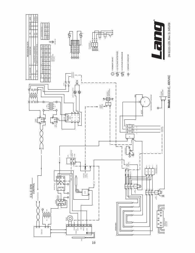
Mod
el: E
CC
O-C
, 480
VAC
2M-6
1111
-129
, Rev
. D, 5
/01/
09
�0
10-1
5-03
5155
5352
5450A
240
STEA
M
HEA
T
FAN
LO
FAN
HI
24VA
C
INTE
RFA
CE
B
BAC
KUP
REL
AY CN
ON
CM
OTO
R H
I
STEA
M B
ACKU
PSW
ITC
H
CO
MPU
TER
TSTA
T
"HEA
T"
STEA
M
CO
NTR
OL
FRO
M"H
EAT"
NO
NC
C
D
SOLE
NO
IDST
EAM
VAL
VE(W
HEN
PR
ESEN
T)
CO
NTR
OL
FRO
M"S
TEAM
" 24 VAC
L
1 2 3321
FUSE
MAI
NC
ON
TAC
TOR
24VA
C
CDB
A
240
24
LIG
HT
SWIT
CH
FRO
M M
AIN
CO
NTA
CTO
R
POW
ER S
WIT
CH
OVE
N L
IGH
TS24
0VAC
DIS
C-S
TAT
HI-L
IMIT
DO
OR
SW
ITC
H
BAC
KUP
SWIT
CH
-C &
-C -S
TMC
ON
TRO
L
TO P
OW
ER S
WIT
CH
BAC
KUP
NO
RM
AL
STEA
M O
FF
OFF
STE
AM
TO C
OM
PUTE
R
12
MO
TOR
NO
NC
C24
BUZZ
ER
RTD
AC
TOP
OPT
ION
ALST
EAM
CO
NTR
OL
RED
BLAC
K
NO
T O
N S
TEAM
UN
ITS
NL1
P1T7
-T4
MT9
ALT.
MO
TOR
HO
OKU
P
BLAC
KR
ED
C
24VA
C
3070
0-06
MAI
NC
ON
TAC
TOR
NN
YEL
SEC
ON
D D
ECK
WIR
ING
IDEN
TIC
ALFI
RST
DEC
K
1 2 3546
SEC
ON
D D
ECK
CIR
CU
IT B
REA
KER
S
D C AB
TER
MIN
AL B
LOC
K24
PO
LE
GR
OU
ND
LU
G
L H
HL
L
= LO
V S
UPR
ESSO
R
= H
I V S
UPR
ESSO
R
= 10
0V S
NU
BBER
= C
ERAM
IC C
APAC
ITO
R
NN
FUSE
DBRN
BRN
5553
5254
5157
5650
TER
MIN
ALS
HEA
TIN
G E
LEM
ENTS
REA
R V
IEW
D
L
240208
XFM
R W
IRE
D F
OR
208
VO
LTS
TO C
HA
NG
E T
O 2
40V
DIS
CO
NN
EC
T R
ED
208
LE
AD
& C
ON
NE
CT
BLU
E 2
40 L
EA
DTO
TE
RM
. BLO
CK
DO
NO
T C
ON
NE
CT
BO
TH.
B
2750
W -
208V
366
7W -
240V
REV
.D
ATE/
ECO
DES
CR
IPTI
ON
OF
CH
ANG
ED
R
C9/
07/2
007
ECO
# 7
002
CO
RR
ECTE
D E
LEC
TRIC
AL R
ATIN
GS
TABL
E &
2ND
DEC
K W
IRE
HO
OKU
PSLR
C
D5/
1/20
09EC
O 7
831
ADD
ED H
I LIM
IT C
ON
TAC
TOR
PER
UL
JMM
ABCD
DWG
. N
O:
SHEE
TO
F
DW
N. D
ATE
:D
WN
. BY
:C
HK. B
Y :
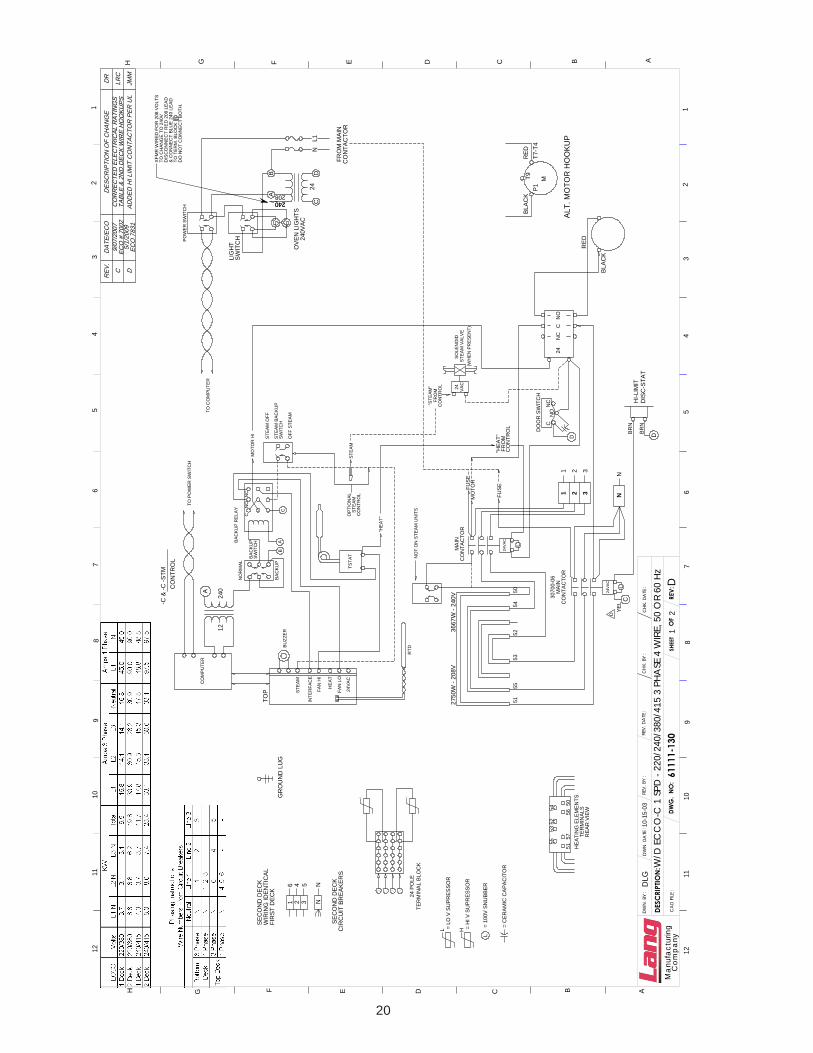
DESC
RIPT
ION
: W/D
EC
CO
-C 1
SPD
- 22
0/24
0/38
0/41
5 3
PHA
SE 4
WIR
E, 5
0 O
R 60
Hz
1
Com
pany
Man
ufac
turin
g61
111-
130
REV:
21
CA
D F
ILE :
CHK
. DA
TE :
REV.
BY
:RE
V. D
ATE
:
EFGHH G F E D C B A
23
45
67
89
1011
12
12
34
56
78
910
1112
DLG
D
��
Mod
el: E
CC
O-C
, 380
/400
VAC
2M-6
1111
-138
, Rev
. C, 5
/1/0
9
1 2 3
CIR
CU
IT B
RE
AK
ER
SS
EC
ON
D D
EC
K
5 3
4 2
6 1
654
= S
NU
BB
ER
100
VAC
L
= LO
VO
LTA
GE
SU
PR
ES
SO
RL
L
RTD
HE
AT
24VA
C
FAN
LO
FAN
HI
INTE
RFA
CE
STE
AM
BU
ZZE
R
H
24
FUS
ES
380
= H
I VO
LTA
GE
SU
PR
ES
SO
RH
= C
ER
AM
IC C
APA
CIT
OR
1 D
EC
K
VO
LTS
L1-L
2L2
-L3
L3-L
1TO
TAL
L1L2
L3
KW
AM
PS
380
5.5
2.8
2.8
11.1
19.5
19.5
13.2
1-6
2 D
EC
K2-
43-
5
L1 11
DE
CK
L2L3
23
SE
RV
ICE
CO
NN
EC
TIO
NS
SE
CO
ND
DE
CK
WIR
ING
IDE
NTI
CA
LFI
RS
T D
EC
KG
RO
UN
D L
UG
2 D
EC
K40
09.
29.
26.
224
.634
.440
.939
.4
2 D
EC
K38
08.
38.
322
.25.
632
.738
.932
.7
12.3
1 D
EC
K40
06.
13.
13.
120
.520
.513
.8 L3 L2
L1
CO
NTR
OL
FRO
M"H
EAT
"
NO
NC
C
SO
LEN
OID
STE
AM
VA
LVE
(WH
EN
PR
ES
EN
T)
CO
NTR
OL
FRO
M"S
TEA
M" 24 VA
C
L
1 2 3321
FUS
E
1 2M
OTO
R
FUS
EM
OTO
R
FIR
ST
DE
CK
24VA
CM
AIN
CO
NTA
CTO
R
5553
5254
5157
5650
5155
5753
5256
5450
A
220
AB
C
BA
CK
UP
RE
LAY
CN
ON
C
MO
TOR
HI S
TEA
M B
AC
KU
P
CO
MP
UTE
R
TSTA
T
"HE
AT"
STE
AM
SW
ITC
H
SW
ITC
HB
AC
KU
P
DO
OR
SW
ITC
H
CIR
CU
IT B
RE
AK
ER
S
TER
MIN
ALS
HE
ATIN
G E
LEM
EN
T
RE
AR
VIE
W
12
TO P
OW
ER
SW
ITC
H
NO
RM
AL
OFF
STE
AM
BA
CK
UP
240
D C AB
24
C
NO
CN
C
NO
T IN
STE
AM
UN
ITS
SW
ITC
HE
NE
RG
Y
D
LIG
HT
B
220
OV
EN
LIG
HTS
240
VA
C
LIG
HT
RE
LAY
SW
ITC
H
PO
WE
RS
WIT
CH
CO
NTA
CTO
RFR
OM
MA
IN
NC C NO
24 V
AC
220
A
DC
OP
TIO
NA
L
STE
AM
CO
NTR
OL
TO C
OM
PU
TER
H1
H4
X1
X4
M
1
21
2
X3
X2
H2
H3
3
NO C
RE
LAY
LIG
HT
NC
24 V
AC
T4-T7
P1
24VA
CM
AIN
CO
NTA
CTO
R
DIS
C-S
TAT
HI L
IMIT
L
-C &
-C -S
TMC
ON
TRO
L
2750
W-3
80V
RE
VIS
ION
BLO
CK
EC
N N
O.
RE
V
C78
31JM
M5/
1/09
AD
DE
D H
I LIM
IT C
ON
TAC
TOR
PE
R U
L
DE
SC
RIP
TIO
ND
R:
DAT
EM
FGE
NG
C
D
D
SK2366 Rev 4/21/2008ECOF Main Assembly
1
5
7
6
1
2
3
4
8
9 10
11
13
16
1017
18
19
20
21
22
10
24
26
27
28
29
30
46
48
49
1
4
10
50
51
47
3233
3435
36
41
42
43
44
4537
383940
31
23
25 Detail AControl Panel Assy
Detail BCan Assembly
14
15
12
10
2M-W
490
FULL
SIZ
E C
ON
VE
CTI
ON
OV
EN
, EC
OF-
C
2M-W
490
FULL
SIZ
E C
ON
VE
CTI
ON
OV
EN
, EC
OF-
C
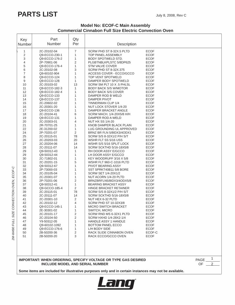
Model No: ECOF-C Main Assembly Commercial Cinnabon Full Size Electric Convection Oven
PARTS LIST July8,2008,RevC
IMPORTANT: WHEN ORDERING, SPECIFY VOLTAGE OR TYPE GAS DESIRED PAGE INCLUDE MODEL AND SERIAL NUMBER OF
Some items are included for illustrative purposes only and in certain instances may not be available.
DescriptionPart
NumberKey
Number
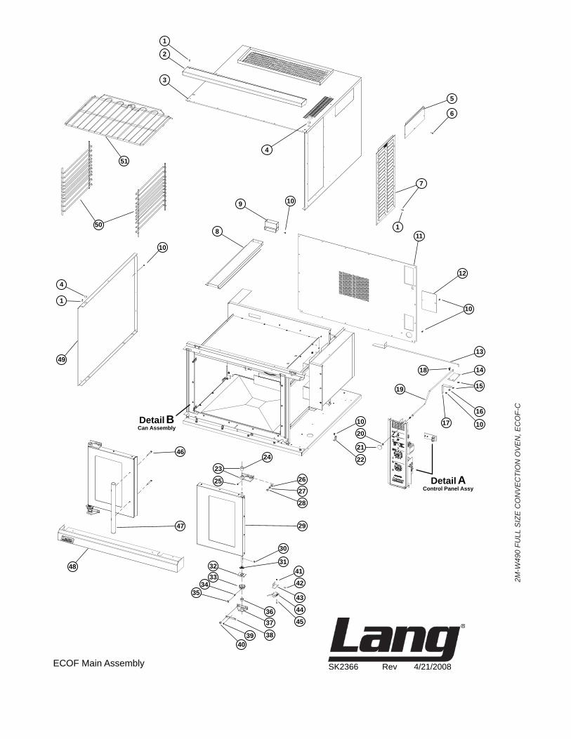
\ 1 2C-20102-04 7 SCRWPHDST8-32X.5PLTD ECOF 2 Q9-ECCO-230-1 1 TOPPANELASSEMBLY ECOF 3 Q9-ECCO-176-2 1 BODYSPOTWELDSTD. ECOF 4 2P-70901-06 2 PLGBTNBLKPLSTC5/8DP625 ECOF 5 Q9-ECCO-176-4 1 STMVALVECOVER ECOF 6 2C-20102-08 3 SCRWPHDST8-32X.375 ECOF 7 Q9-60102-904 1 ACCESSCOVER-ECCO/GCCO ECOF 8 Q9-ECCO-124 1 TOPVENTSPOTWELD ECOF 9 Q9-ECCO-128 1 DAMPERBODYSPOTWELD ECOF 10 2C-20103-02 13 SCRWSMPLT10X.5PHLSL ECOF 11 Q9-ECCO-182-3 1 BODYBACKS/SW/MOTOR ECOF 12 Q9-ECCO-182-4 1 BODYBACKS/SCOVER ECOF 13 Q9-ECCO-133 1 DAMPERRODBWELD ECOF 14 Q9-ECCO-137 1 DAMPERPIVOT ECOF 15 2C-20602-02 1 TINNERMANCLIP1/4 ECOF 16 2C-20301-20 1 NUTLOCKSTOVER1/4-20 ECOF 17 Q9-ECCO-136 1 DAMPERBRACKETANGLE ECOF 18 2C-20104-41 6 SCRWMACH.1/4-20X5/8H/H ECOF 19 Q9-ECCO-131 1 DAMPERRODAWELD ECOF 20 2C-20303-01 4 NUTHXSS1/4-20 ECOF 21 2R-70701-25 1 KNOBDAMPERBLACKPLAIN ECOF 22 2E-31200-02 1 LUGGROUNDINGULAPPROVED ECOF 24 2P-70201-07 2 BRNZBRFLN5/8IDX3/4ODX1 ECOF 25 2C-20115-01 78 SCRWS/S8-32X1/2P/HS/T ECOF 26 2C-20203-03 20 WSHRFLTSS5/16USS ECOF 27 2C-20204-06 14 WSHRS/S5/16SPLITLOCK ECOF 28 2C-20111-07 14 SCRWSCKTHD5/16-18X5/8 ECOF 29 Q9-50312-43 1 RHDOORASSYE/GCCO ECOF 29 Q9-50312-44 1 LHDOORASSYE/GCCO ECOF 30 2C-71802-01 1 KEYWOODRUFF3/16X5/8 ECOF 31 2C-20201-15 5 WSHRFLT960-C-1016PLTD ECOF 32 Q9-50312-67 1 PIVOTBEARINGASSY ECOF 33 2P-73000-03 1 SSTSPRKT40B115/8BORE ECOF 34 2C-20105-04 1 SCRWSET1/4-20X1/2 ECOF 35 2C-20301-07 1 NUTACORN1/4-20PLTD ECOF 36 2P-70201-06 2 BRNZBRFLN5/8IDX3/4ODX5/8 ECOF 37 Q9-50312-41 1 BEARINGBRACKETASSY ECOF 38 Q9-GCCO-185-4 2 HINGEBRACKETRETAINER ECOF 39 2C-20115-01 78 SCRWS/S8-32X1/2P/HS/T ECOF 40 2C-20111-07 14 SCRWSCKTHD5/16-18X5/8 ECOF 41 2C-20301-10 2 NUTHEX6-32PLTD ECOF 42 2C-20102-12 4 SCRWPHDST10-32X3/8 ECOF 43 Q9-ECCO-145-1 1 MICROSWITCHBRACKET ECOF 44 2E-30301-02 1 SWITCH,MICRO ECOF 45 2C-20101-17 2 SCRWRNDMS6-32X1PLTD ECOF 46 2C-20104-50 2 SCRWHXHD1/4-28X2-1/4 ECOF 47 Y9-50312-05 1 HANDLEASSY1HANDLE ECOF 48 Q9-60102-1092 1 BOTTOMPANELECCO ECOF 49 Q9-ECCO-176-6 1 L/HBODYSIDE ECOF 50 2B-50200-36 2 RACKSLIDECINNABONOVEN ECOF-C 51 2B-50200-20 3 RACKECCO/GCCOOVEN ECOF
1 2
QtyPer
2M-W
490
FULL
SIZ
E C
ON
VE
CTI
ON
OV
EN
, EC
OF-
C
2M-W
490
FULL
SIZ
E C
ON
VE
CTI
ON
OV
EN
, EC
OF-
C
PARTS LIST July8,2008,RevC
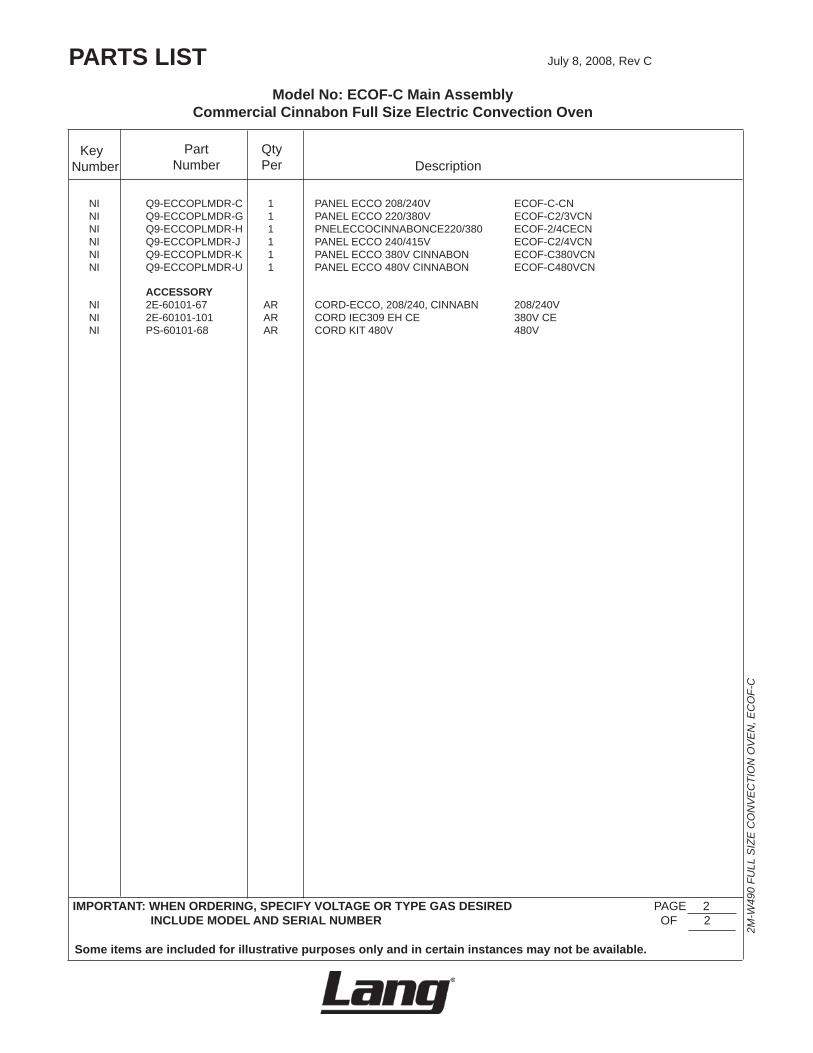
IMPORTANT: WHEN ORDERING, SPECIFY VOLTAGE OR TYPE GAS DESIRED PAGE2 INCLUDE MODEL AND SERIAL NUMBER OF2
Some items are included for illustrative purposes only and in certain instances may not be available.
DescriptionPart
NumberKey
Number
NI Q9-ECCOPLMDR-C 1 PANELECCO208/240V ECOF-C-CN NI Q9-ECCOPLMDR-G 1 PANELECCO220/380V ECOF-C2/3VCN NI Q9-ECCOPLMDR-H 1 PNELECCOCINNABONCE220/380 ECOF-2/4CECN NI Q9-ECCOPLMDR-J 1 PANELECCO240/415V ECOF-C2/4VCN NI Q9-ECCOPLMDR-K 1 PANELECCO380VCINNABON ECOF-C380VCN NI Q9-ECCOPLMDR-U 1 PANELECCO480VCINNABON ECOF-C480VCN
ACCESSORY NI 2E-60101-67 AR CORD-ECCO,208/240,CINNABN 208/240V NI 2E-60101-101 AR CORDIEC309EHCE 380VCE NI PS-60101-68 AR CORDKIT480V 480V
QtyPer
Model No: ECOF-C Main Assembly Commercial Cinnabon Full Size Electric Convection Oven
2M-W
490
FULL
SIZ
E C
ON
VE
CTI
ON
OV
EN
, EC
OF-
C
2M-W
490
FULL
SIZ
E C
ON
VE
CTI
ON
OV
EN
, EC
OF-
C

1
9 10
121
11
81
6
17
563
16
23
29
24
32
1
1
2311
2830
17
35
36
4142
34
44
43
371138
2526
27
3940
18
19
311
2122
33
20
1314
15
4
2
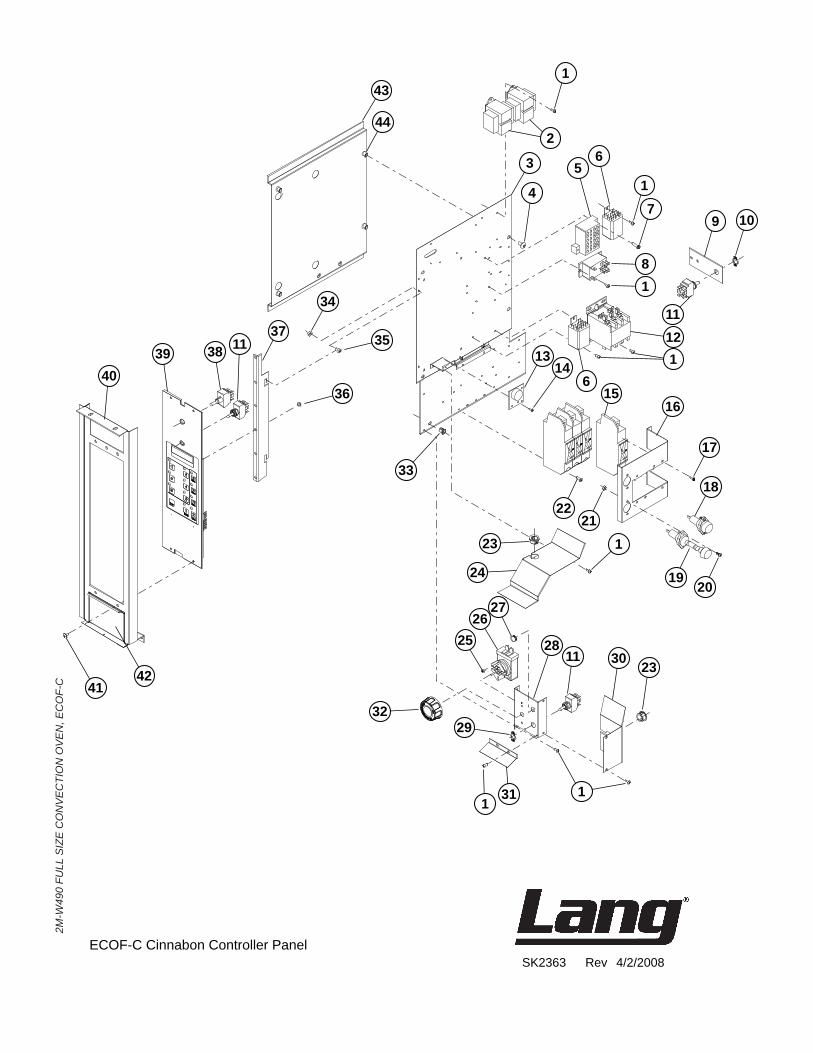
SK2363 Rev 4/2/2008ECOF-C Cinnabon Controller Panel
2M-W
490
FULL
SIZ
E C
ON
VE
CTI
ON
OV
EN
, EC
OF-
C
2M-W
490
FULL
SIZ
E C
ON
VE
CTI
ON
OV
EN
, EC
OF-
C
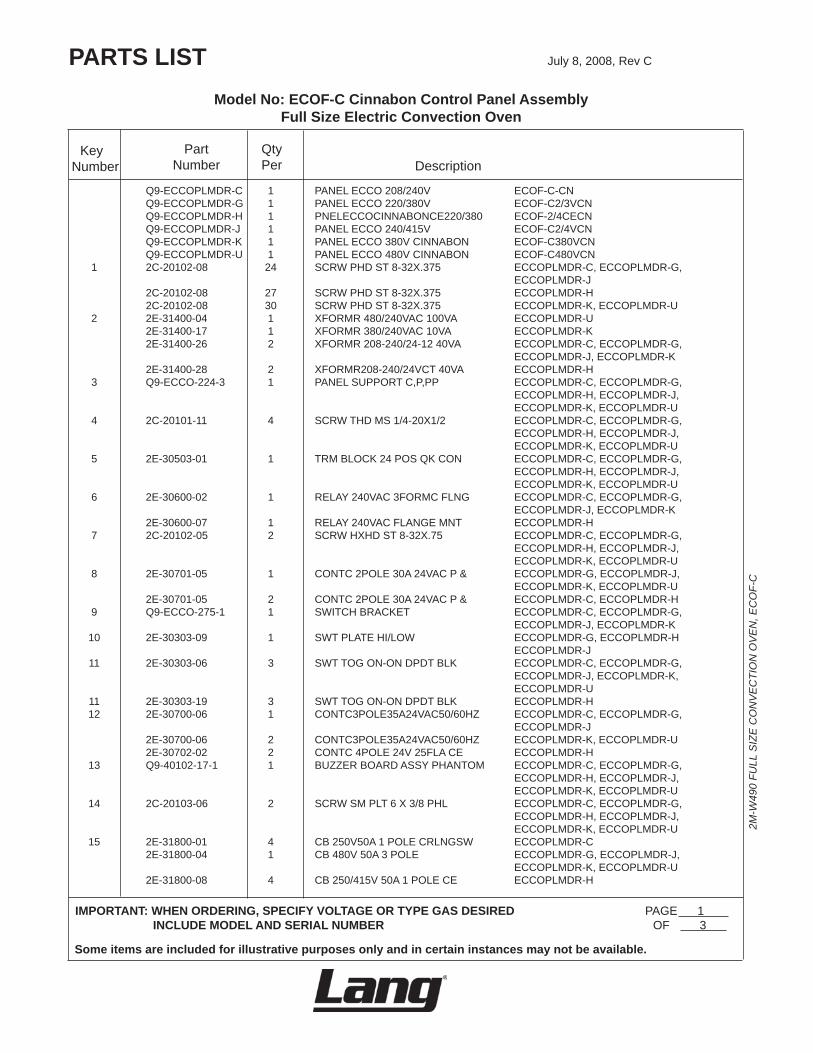
Model No: ECOF-C Cinnabon Control Panel Assembly Full Size Electric Convection Oven
PARTS LIST July8,2008,RevC
IMPORTANT: WHEN ORDERING, SPECIFY VOLTAGE OR TYPE GAS DESIRED PAGE1 INCLUDE MODEL AND SERIAL NUMBER OF3
Some items are included for illustrative purposes only and in certain instances may not be available.
DescriptionPart
NumberKey
Number
Q9-ECCOPLMDR-C 1 PANELECCO208/240V ECOF-C-CN Q9-ECCOPLMDR-G 1 PANELECCO220/380V ECOF-C2/3VCN Q9-ECCOPLMDR-H 1 PNELECCOCINNABONCE220/380 ECOF-2/4CECN Q9-ECCOPLMDR-J 1 PANELECCO240/415V ECOF-C2/4VCN Q9-ECCOPLMDR-K 1 PANELECCO380VCINNABON ECOF-C380VCN Q9-ECCOPLMDR-U 1 PANELECCO480VCINNABON ECOF-C480VCN 1 2C-20102-08 24 SCRWPHDST8-32X.375 ECCOPLMDR-C,ECCOPLMDR-G,
ECCOPLMDR-J 2C-20102-08 27 SCRWPHDST8-32X.375 ECCOPLMDR-H 2C-20102-08 30 SCRWPHDST8-32X.375 ECCOPLMDR-K,ECCOPLMDR-U 2 2E-31400-04 1 XFORMR480/240VAC100VA ECCOPLMDR-U 2E-31400-17 1 XFORMR380/240VAC10VA ECCOPLMDR-K 2E-31400-26 2 XFORMR208-240/24-1240VA ECCOPLMDR-C,ECCOPLMDR-G,
ECCOPLMDR-J,ECCOPLMDR-K 2E-31400-28 2 XFORMR208-240/24VCT40VA ECCOPLMDR-H 3 Q9-ECCO-224-3 1 PANELSUPPORTC,P,PP ECCOPLMDR-C,ECCOPLMDR-G,
ECCOPLMDR-H,ECCOPLMDR-J,ECCOPLMDR-K,ECCOPLMDR-U
4 2C-20101-11 4 SCRWTHDMS1/4-20X1/2 ECCOPLMDR-C,ECCOPLMDR-G,ECCOPLMDR-H,ECCOPLMDR-J,ECCOPLMDR-K,ECCOPLMDR-U
5 2E-30503-01 1 TRMBLOCK24POSQKCON ECCOPLMDR-C,ECCOPLMDR-G,ECCOPLMDR-H,ECCOPLMDR-J,ECCOPLMDR-K,ECCOPLMDR-U
6 2E-30600-02 1 RELAY240VAC3FORMCFLNG ECCOPLMDR-C,ECCOPLMDR-G,ECCOPLMDR-J,ECCOPLMDR-K
2E-30600-07 1 RELAY240VACFLANGEMNT ECCOPLMDR-H 7 2C-20102-05 2 SCRWHXHDST8-32X.75 ECCOPLMDR-C,ECCOPLMDR-G,
ECCOPLMDR-H,ECCOPLMDR-J,ECCOPLMDR-K,ECCOPLMDR-U
8 2E-30701-05 1 CONTC2POLE30A24VACP& ECCOPLMDR-G,ECCOPLMDR-J,ECCOPLMDR-K,ECCOPLMDR-U
2E-30701-05 2 CONTC2POLE30A24VACP& ECCOPLMDR-C,ECCOPLMDR-H 9 Q9-ECCO-275-1 1 SWITCHBRACKET ECCOPLMDR-C,ECCOPLMDR-G,
ECCOPLMDR-J,ECCOPLMDR-K 10 2E-30303-09 1 SWTPLATEHI/LOW ECCOPLMDR-G,ECCOPLMDR-H
ECCOPLMDR-J 11 2E-30303-06 3 SWTTOGON-ONDPDTBLK ECCOPLMDR-C,ECCOPLMDR-G,
ECCOPLMDR-J,ECCOPLMDR-K,ECCOPLMDR-U
11 2E-30303-19 3 SWTTOGON-ONDPDTBLK ECCOPLMDR-H 12 2E-30700-06 1 CONTC3POLE35A24VAC50/60HZ ECCOPLMDR-C,ECCOPLMDR-G,
ECCOPLMDR-J 2E-30700-06 2 CONTC3POLE35A24VAC50/60HZ ECCOPLMDR-K,ECCOPLMDR-U 2E-30702-02 2 CONTC4POLE24V25FLACE ECCOPLMDR-H 13 Q9-40102-17-1 1 BUZZERBOARDASSYPHANTOM ECCOPLMDR-C,ECCOPLMDR-G,
ECCOPLMDR-H,ECCOPLMDR-J,ECCOPLMDR-K,ECCOPLMDR-U
14 2C-20103-06 2 SCRWSMPLT6X3/8PHL ECCOPLMDR-C,ECCOPLMDR-G,ECCOPLMDR-H,ECCOPLMDR-J,ECCOPLMDR-K,ECCOPLMDR-U
15 2E-31800-01 4 CB250V50A1POLECRLNGSW ECCOPLMDR-C 2E-31800-04 1 CB480V50A3POLE ECCOPLMDR-G,ECCOPLMDR-J,
ECCOPLMDR-K,ECCOPLMDR-U 2E-31800-08 4 CB250/415V50A1POLECE ECCOPLMDR-H
QtyPer
2M-W
490
FULL
SIZ
E C
ON
VE
CTI
ON
OV
EN
, EC
OF-
C
2M-W
490
FULL
SIZ
E C
ON
VE
CTI
ON
OV
EN
, EC
OF-
C
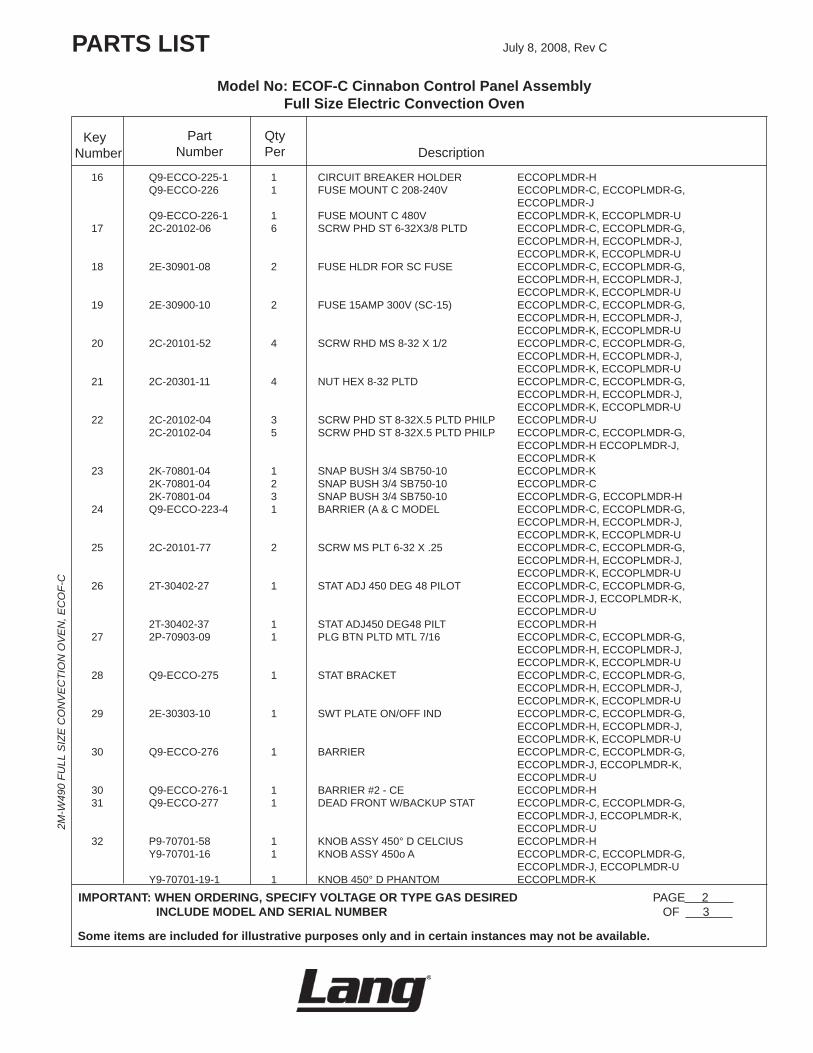
Model No: ECOF-C Cinnabon Control Panel Assembly Full Size Electric Convection Oven
PARTS LIST July8,2008,RevC
IMPORTANT: WHEN ORDERING, SPECIFY VOLTAGE OR TYPE GAS DESIRED PAGE2 INCLUDE MODEL AND SERIAL NUMBER OF3
Some items are included for illustrative purposes only and in certain instances may not be available.
DescriptionPart
NumberKey
Number
16 Q9-ECCO-225-1 1 CIRCUITBREAKERHOLDER ECCOPLMDR-H Q9-ECCO-226 1 FUSEMOUNTC208-240V ECCOPLMDR-C,ECCOPLMDR-G,
ECCOPLMDR-J Q9-ECCO-226-1 1 FUSEMOUNTC480V ECCOPLMDR-K,ECCOPLMDR-U 17 2C-20102-06 6 SCRWPHDST6-32X3/8PLTD ECCOPLMDR-C,ECCOPLMDR-G,
ECCOPLMDR-H,ECCOPLMDR-J,ECCOPLMDR-K,ECCOPLMDR-U
18 2E-30901-08 2 FUSEHLDRFORSCFUSE ECCOPLMDR-C,ECCOPLMDR-G,ECCOPLMDR-H,ECCOPLMDR-J,ECCOPLMDR-K,ECCOPLMDR-U
19 2E-30900-10 2 FUSE15AMP300V(SC-15) ECCOPLMDR-C,ECCOPLMDR-G,ECCOPLMDR-H,ECCOPLMDR-J,ECCOPLMDR-K,ECCOPLMDR-U
20 2C-20101-52 4 SCRWRHDMS8-32X1/2 ECCOPLMDR-C,ECCOPLMDR-G,ECCOPLMDR-H,ECCOPLMDR-J,ECCOPLMDR-K,ECCOPLMDR-U
21 2C-20301-11 4 NUTHEX8-32PLTD ECCOPLMDR-C,ECCOPLMDR-G,ECCOPLMDR-H,ECCOPLMDR-J,ECCOPLMDR-K,ECCOPLMDR-U
22 2C-20102-04 3 SCRWPHDST8-32X.5PLTDPHILP ECCOPLMDR-U 2C-20102-04 5 SCRWPHDST8-32X.5PLTDPHILP ECCOPLMDR-C,ECCOPLMDR-G,
ECCOPLMDR-HECCOPLMDR-J,ECCOPLMDR-K
23 2K-70801-04 1 SNAPBUSH3/4SB750-10 ECCOPLMDR-K 2K-70801-04 2 SNAPBUSH3/4SB750-10 ECCOPLMDR-C 2K-70801-04 3 SNAPBUSH3/4SB750-10 ECCOPLMDR-G,ECCOPLMDR-H 24 Q9-ECCO-223-4 1 BARRIER(A&CMODEL ECCOPLMDR-C,ECCOPLMDR-G,
ECCOPLMDR-H,ECCOPLMDR-J,ECCOPLMDR-K,ECCOPLMDR-U
25 2C-20101-77 2 SCRWMSPLT6-32X.25 ECCOPLMDR-C,ECCOPLMDR-G,ECCOPLMDR-H,ECCOPLMDR-J,ECCOPLMDR-K,ECCOPLMDR-U
26 2T-30402-27 1 STATADJ450DEG48PILOT ECCOPLMDR-C,ECCOPLMDR-G,ECCOPLMDR-J,ECCOPLMDR-K,ECCOPLMDR-U
2T-30402-37 1 STATADJ450DEG48PILT ECCOPLMDR-H 27 2P-70903-09 1 PLGBTNPLTDMTL7/16 ECCOPLMDR-C,ECCOPLMDR-G,
ECCOPLMDR-H,ECCOPLMDR-J,ECCOPLMDR-K,ECCOPLMDR-U
28 Q9-ECCO-275 1 STATBRACKET ECCOPLMDR-C,ECCOPLMDR-G,ECCOPLMDR-H,ECCOPLMDR-J,ECCOPLMDR-K,ECCOPLMDR-U
29 2E-30303-10 1 SWTPLATEON/OFFIND ECCOPLMDR-C,ECCOPLMDR-G,ECCOPLMDR-H,ECCOPLMDR-J,ECCOPLMDR-K,ECCOPLMDR-U
30 Q9-ECCO-276 1 BARRIER ECCOPLMDR-C,ECCOPLMDR-G,ECCOPLMDR-J,ECCOPLMDR-K,ECCOPLMDR-U
30 Q9-ECCO-276-1 1 BARRIER#2-CE ECCOPLMDR-H 31 Q9-ECCO-277 1 DEADFRONTW/BACKUPSTAT ECCOPLMDR-C,ECCOPLMDR-G,
ECCOPLMDR-J,ECCOPLMDR-K,ECCOPLMDR-U
32 P9-70701-58 1 KNOBASSY450°DCELCIUS ECCOPLMDR-H Y9-70701-16 1 KNOBASSY450oA ECCOPLMDR-C,ECCOPLMDR-G,
ECCOPLMDR-J,ECCOPLMDR-U Y9-70701-19-1 1 KNOB450°DPHANTOM ECCOPLMDR-K
QtyPer
2M-W
490
FULL
SIZ
E C
ON
VE
CTI
ON
OV
EN
, EC
OF-
C
2M-W
490
FULL
SIZ
E C
ON
VE
CTI
ON
OV
EN
, EC
OF-
C
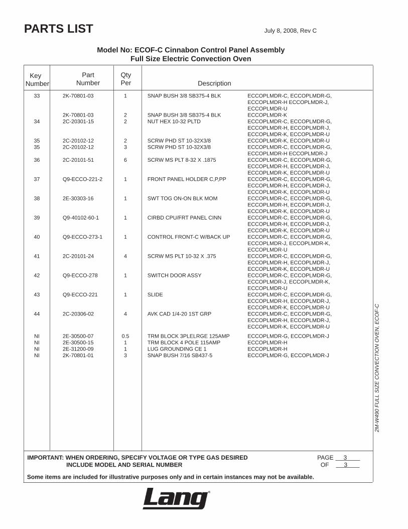
Model No: ECOF-C Cinnabon Control Panel Assembly Full Size Electric Convection Oven
PARTS LIST July8,2008,RevC
IMPORTANT: WHEN ORDERING, SPECIFY VOLTAGE OR TYPE GAS DESIRED PAGE3 INCLUDE MODEL AND SERIAL NUMBER OF3
Some items are included for illustrative purposes only and in certain instances may not be available.
DescriptionPart
NumberKey
Number
33 2K-70801-03 1 SNAPBUSH3/8SB375-4BLK ECCOPLMDR-C,ECCOPLMDR-G,ECCOPLMDR-HECCOPLMDR-J,ECCOPLMDR-U
2K-70801-03 2 SNAPBUSH3/8SB375-4BLK ECCOPLMDR-K 34 2C-20301-15 2 NUTHEX10-32PLTD ECCOPLMDR-C,ECCOPLMDR-G,
ECCOPLMDR-H,ECCOPLMDR-J,ECCOPLMDR-K,ECCOPLMDR-U
35 2C-20102-12 2 SCRWPHDST10-32X3/8 ECCOPLMDR-K,ECCOPLMDR-U 35 2C-20102-12 3 SCRWPHDST10-32X3/8 ECCOPLMDR-C,ECCOPLMDR-G,
ECCOPLMDR-HECCOPLMDR-J 36 2C-20101-51 6 SCRWMSPLT8-32X.1875 ECCOPLMDR-C,ECCOPLMDR-G,
ECCOPLMDR-H,ECCOPLMDR-J,ECCOPLMDR-K,ECCOPLMDR-U
37 Q9-ECCO-221-2 1 FRONTPANELHOLDERC,P,PP ECCOPLMDR-C,ECCOPLMDR-G,ECCOPLMDR-H,ECCOPLMDR-J,ECCOPLMDR-K,ECCOPLMDR-U
38 2E-30303-16 1 SWTTOGON-ONBLKMOM ECCOPLMDR-C,ECCOPLMDR-G,ECCOPLMDR-H,ECCOPLMDR-J,ECCOPLMDR-K,ECCOPLMDR-U
39 Q9-40102-60-1 1 CIRBDCPU/FRTPANELCINN ECCOPLMDR-C,ECCOPLMDR-G,ECCOPLMDR-H,ECCOPLMDR-J,ECCOPLMDR-K,ECCOPLMDR-U
40 Q9-ECCO-273-1 1 CONTROLFRONT-CW/BACKUP ECCOPLMDR-C,ECCOPLMDR-G,ECCOPLMDR-J,ECCOPLMDR-K,ECCOPLMDR-U
41 2C-20101-24 4 SCRWMSPLT10-32X.375 ECCOPLMDR-C,ECCOPLMDR-G,ECCOPLMDR-H,ECCOPLMDR-J,ECCOPLMDR-K,ECCOPLMDR-U
42 Q9-ECCO-278 1 SWITCHDOORASSY ECCOPLMDR-C,ECCOPLMDR-G,ECCOPLMDR-J,ECCOPLMDR-K,ECCOPLMDR-U
43 Q9-ECCO-221 1 SLIDE ECCOPLMDR-C,ECCOPLMDR-G,ECCOPLMDR-H,ECCOPLMDR-J,ECCOPLMDR-K,ECCOPLMDR-U
44 2C-20306-02 4 AVKCAD1/4-201STGRP ECCOPLMDR-C,ECCOPLMDR-G,ECCOPLMDR-H,ECCOPLMDR-J,ECCOPLMDR-K,ECCOPLMDR-U
NI 2E-30500-07 0.5 TRMBLOCK3PLELRGE125AMP ECCOPLMDR-G,ECCOPLMDR-J NI 2E-30500-15 1 TRMBLOCK4POLE115AMP ECCOPLMDR-H NI 2E-31200-09 1 LUGGROUNDINGCE1 ECCOPLMDR-H NI 2K-70801-01 3 SNAPBUSH7/16SB437-5 ECCOPLMDR-G,ECCOPLMDR-J
QtyPer
2M-W
490
FULL
SIZ
E C
ON
VE
CTI
ON
OV
EN
, EC
OF-
C
2M-W
490
FULL
SIZ
E C
ON
VE
CTI
ON
OV
EN
, EC
OF-
C
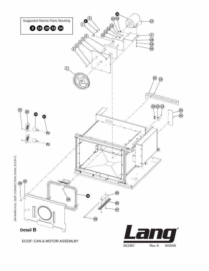
SK2367 Rev. A 6/03/08ECOF: CAN & MOTOR ASSEMLBY
Detail B
168 28 33 34
Suggested Marine Parts Stocking
1
23
45
6
78
9
10
1417
4
18
19
20
21 13
15 22 1323
25
26
27
35
28
3031
2732
3334
29
24
1516
1112
13
2M-W
490
FULL
SIZ
E C
ON
VE
CTI
ON
OV
EN
, EC
OF-
C
2M-W
490
FULL
SIZ
E C
ON
VE
CTI
ON
OV
EN
, EC
OF-
C
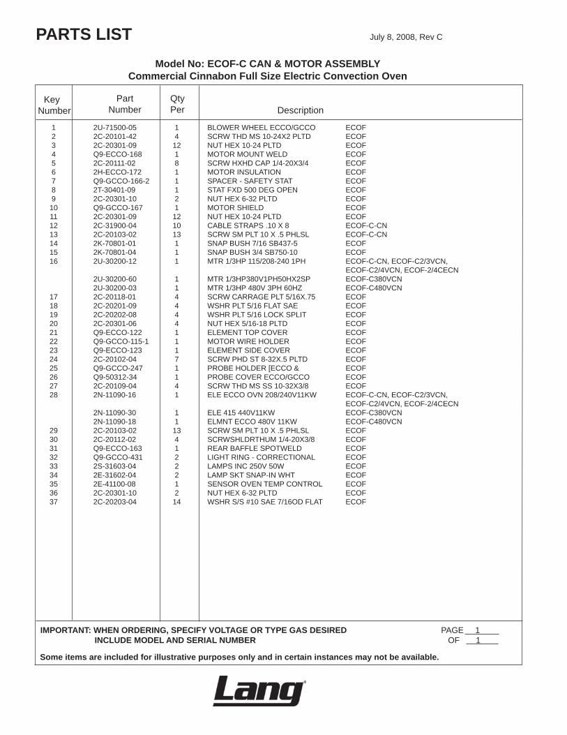
Model No: ECOF-C CAN & MOTOR ASSEMBLY Commercial Cinnabon Full Size Electric Convection Oven
PARTS LIST July8,2008,RevC
IMPORTANT: WHEN ORDERING, SPECIFY VOLTAGE OR TYPE GAS DESIRED PAGE1 INCLUDE MODEL AND SERIAL NUMBER OF1
Some items are included for illustrative purposes only and in certain instances may not be available.
DescriptionPart
NumberKey
Number
1 2U-71500-05 1 BLOWERWHEELECCO/GCCO ECOF 2 2C-20101-42 4 SCRWTHDMS10-24X2PLTD ECOF 3 2C-20301-09 12 NUTHEX10-24PLTD ECOF 4 Q9-ECCO-168 1 MOTORMOUNTWELD ECOF 5 2C-20111-02 8 SCRWHXHDCAP1/4-20X3/4 ECOF 6 2H-ECCO-172 1 MOTORINSULATION ECOF 7 Q9-GCCO-166-2 1 SPACER-SAFETYSTAT ECOF 8 2T-30401-09 1 STATFXD500DEGOPEN ECOF 9 2C-20301-10 2 NUTHEX6-32PLTD ECOF 10 Q9-GCCO-167 1 MOTORSHIELD ECOF 11 2C-20301-09 12 NUTHEX10-24PLTD ECOF 12 2C-31900-04 10 CABLESTRAPS.10X8 ECOF-C-CN 13 2C-20103-02 13 SCRWSMPLT10X.5PHLSL ECOF-C-CN 14 2K-70801-01 1 SNAPBUSH7/16SB437-5 ECOF 15 2K-70801-04 1 SNAPBUSH3/4SB750-10 ECOF 16 2U-30200-12 1 MTR1/3HP115/208-2401PH ECOF-C-CN,ECOF-C2/3VCN,
ECOF-C2/4VCN,ECOF-2/4CECN 2U-30200-60 1 MTR1/3HP380V1PH50HX2SP ECOF-C380VCN 2U-30200-03 1 MTR1/3HP480V3PH60HZ ECOF-C480VCN 17 2C-20118-01 4 SCRWCARRAGEPLT5/16X.75 ECOF 18 2C-20201-09 4 WSHRPLT5/16FLATSAE ECOF 19 2C-20202-08 4 WSHRPLT5/16LOCKSPLIT ECOF 20 2C-20301-06 4 NUTHEX5/16-18PLTD ECOF 21 Q9-ECCO-122 1 ELEMENTTOPCOVER ECOF 22 Q9-GCCO-115-1 1 MOTORWIREHOLDER ECOF 23 Q9-ECCO-123 1 ELEMENTSIDECOVER ECOF 24 2C-20102-04 7 SCRWPHDST8-32X.5PLTD ECOF 25 Q9-GCCO-247 1 PROBEHOLDER[ECCO& ECOF 26 Q9-50312-34 1 PROBECOVERECCO/GCCO ECOF 27 2C-20109-04 4 SCRWTHDMSSS10-32X3/8 ECOF 28 2N-11090-16 1 ELEECCOOVN208/240V11KW ECOF-C-CN,ECOF-C2/3VCN,
ECOF-C2/4VCN,ECOF-2/4CECN 2N-11090-30 1 ELE415440V11KW ECOF-C380VCN 2N-11090-18 1 ELMNTECCO480V11KW ECOF-C480VCN 29 2C-20103-02 13 SCRWSMPLT10X.5PHLSL ECOF 30 2C-20112-02 4 SCRWSHLDRTHUM1/4-20X3/8 ECOF 31 Q9-ECCO-163 1 REARBAFFLESPOTWELD ECOF 32 Q9-GCCO-431 2 LIGHTRING-CORRECTIONAL ECOF 33 2S-31603-04 2 LAMPSINC250V50W ECOF 34 2E-31602-04 2 LAMPSKTSNAP-INWHT ECOF 35 2E-41100-08 1 SENSOROVENTEMPCONTROL ECOF 36 2C-20301-10 2 NUTHEX6-32PLTD ECOF 37 2C-20203-04 14 WSHRS/S#10SAE7/16ODFLAT ECOF
QtyPer

STAR INTERNATIONAL HOLDINGS INC. COMPANYStar - Holman - Lang - Wells - Bloomfield - Toastmaster
10 Sunnen Drive, St. Louis, MO 63143 U.S.A.(314) 678-6303
www.star-mfg.com