Embed Size (px)
Citation preview
H. M.Garon 1, J. S.Gal-Edd, K.W. Dearth, V.J.Sank1NASA Goddard Space Flight Center, Greenbelt, MD 2077122 June 2010
Report on Earth Observation Application
Landsat Data Continuity Mission (LDCM) - Optimizing X-band Usage
Summary:
The NASA version of the low-density parity check (LDPC) 7/8-rate code, shortened to the dimensions of
(8160, 7136), has been implemented as the forward error correction (FEC) schema for the Landsat Data
Continuity Mission (LDCM). This is the first flight application of this code. In order to place a 440 Msps
link within the 375 MHz wide X band we found it necessary to heavily bandpass filter the satellite
transmitter output . Despite the significant amplitude and phase distortions that accompanied the
spectral truncation, the mission required BER is maintained at < 10 -12 with less than 2 dB of
implementation loss. We utilized a band-pass filter designed ostensibly to replicate the link distortions
to demonstrate link design viability. The same filter was then used to optimize the adaptive equalizer in
the receiver employed at the terminus of the downlink. The excellent results we obtained could be
directly attributed to the implementation of the LDPC code and the amplitude and phase compensation
provided in the receiver. Similar results were obtained with receivers from several vendors.
Background:
New near-earth missions are continually pushing for higher data throughput. Sensors planned for
installation aboard demand ever increasing associated data rates. Ground station infrastructures have
in turn seen the benefit of improved efficiencies in the handling and distribution of mission data such
that their capacities have improved dramatically as well. In contrast, the X-band spectrum allocated to
near-earth missions (8025 to 8400 MHz) is constrained. In keeping with the output capabilities of its
intended sensors aboard, LDCM earth-observation science data required a downlink information rate of
384 Mbps. This information rate, limited contact time, large file sizes combined with file compression
served to stipulate that in order to survive logistically the mission must achieve a bit error rate (BER)
less than 10 -12 . An additional complication was the physical constraint associated with the presence of
the Deep Space Network (DSN) at 8400 MHz. The requirement here for both LDCM and DSN to co-
survive was simply that that the power spectral flux density (PSFD) at the DSN antenna not exceed -225
dBm/(Hz m2) from any potentially interfering source. In order to meet these restrictions and still satisfy
the basic power requirements for maintaining a link, the LDCM spacecraft RF emissions must then be
severely filtered. The maximum bandwidth that LDCM could occupy was 375 MHz, asymmetrical about
an assigned carrier frequency of 8200 MHz. However, filtering not only truncates the transmission
spectrum it also impresses significant amplitude and phase distortion on the link. What was not so
obvious several years ago was how to select an appropriate high rate code from the available codes. The
subclass of Euclidean geometry LDPC codes was just being promulgated by NASA as potentially useful
for a wide range of space communication applications [1-4], several years behind its competitors of
serially concatenated convolutional turbo-codes and DVB-S2. DVB-S2 concatenated a variable-rate
1 of 7
https://ntrs.nasa.gov/search.jsp?R=20100026439 2020-02-28T01:43:52+00:00Z
2 of 7
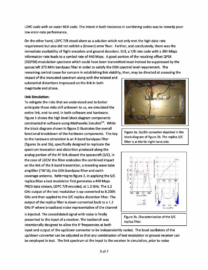
Figure 3a. Up/Dn converter depicted in the
block diagram of figure 2b. The replica S/C
filter is at the far right hand side.
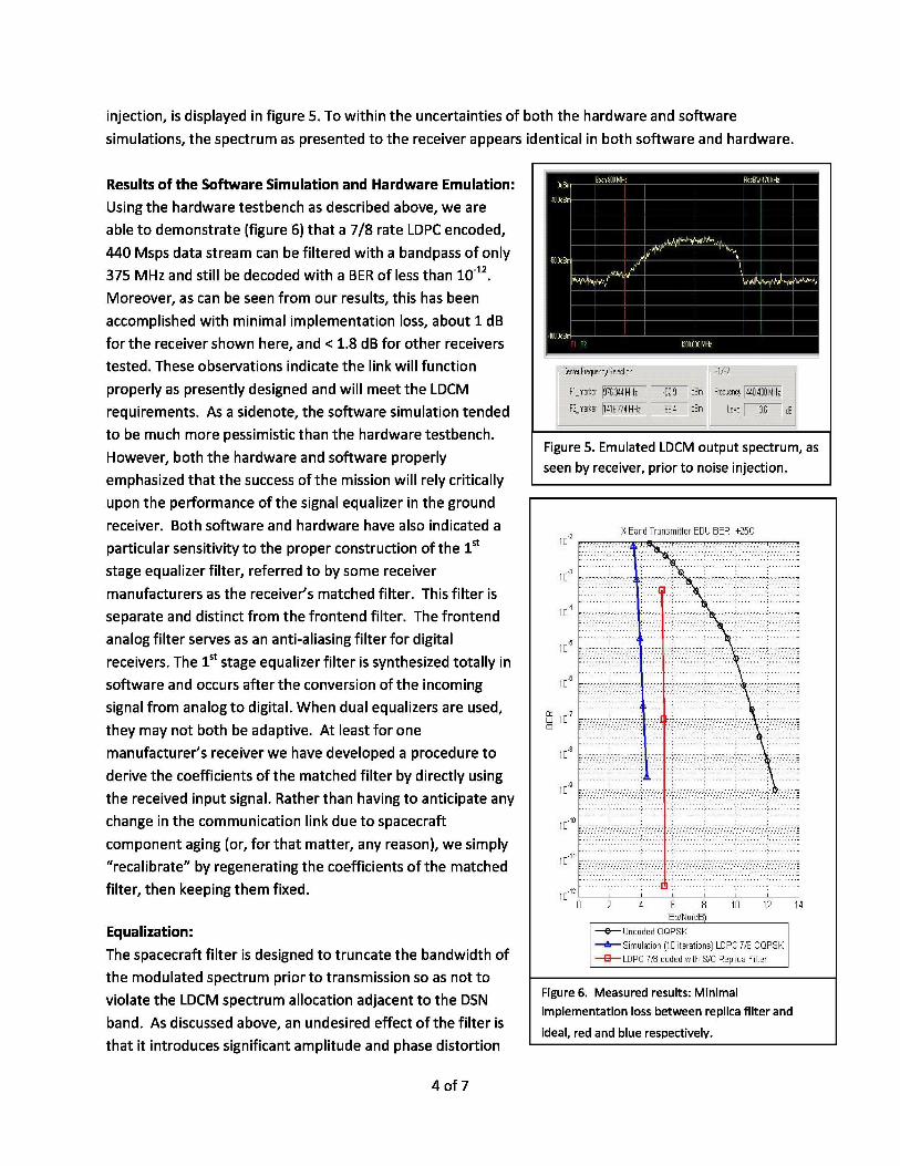
Figure 3b. Characterization of the S/C
replica filter.
LDPC code with an outer BCH code. The intent in both instances in combining codes was to remedy poor
low error-rate performance.
On the other hand, LDPC 7/8 stood alone as a solution which not only met the high-data rate
requirement but also did not exhibit a (known) error floor. Further, and conclusively, there was the
immediate availability of flight encoders and ground decoders. Still, a 7/8 rate code with a 384 Mbps
information rate leads to a symbol rate of 440 Msps. A good portion of the resulting offset QPSK
(OQPSK) modulation spectrum which could have been transmitted must instead be suppressed by the
spacecraft 375 MHz bandpass filter in order to satisfy the DSN spectral level requirement. The
remaining central cause for concern in establishing link viability, then, may be directed at assessing the
impact of this truncated spectrum along with the related and
substantial distortions impressed on the link in both
magnitude and phase.
Link Simulation:
To mitigate the risks that we understood and to better
anticipate those risks still unknown to us, we simulated the
entire link, end-to-end, in both software and hardware.
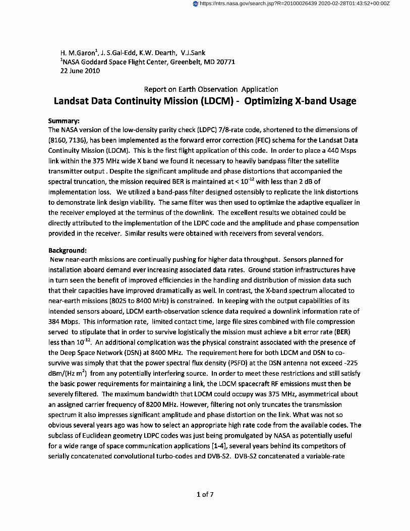
Figure 1 shows the high level block diagram components
constructed in software using Mathworks Simulinktm. While
the block diagram shown in figure 2 illustrates the overall
functional breakdown of the hardware components. The key
to the hardware simulation is an X-band bandpass filter
(figures 3a and 3b), specifically designed to replicate the
spectrum truncation and distortion produced along the
analog portion of the RF link aboard the spacecraft (S/C). In
the case of LDCM the filter embodies the combined impact
on the link of the X-band transmitter, a traveling wave tube
amplifier (TWTA), the DSN bandpass filter and earth
coverage antenna. Referring to figure 2, in applying the S/C
replica filter a test modulator first generates a 440 Msps
PN23 data stream, LDPC 7/8 encoded, at 1.2 GHz. The 1.2
GHz output of the test modulator is up-converted to 8.2005
GHz and then applied to the S/C replica distortion filter. The
output of the replica filter is down-converted back to a 1.2
GHz IF where broadband noise representative of the channel
is injected. The consolidated signal with noise is finally
presented to the input of a receiver. The testbench was
intentionally designed to allow the IF frequencies at both
input and output of the up/down converter to be independently varied. The local oscillators of the
up/down converter can be adjusted so that any combination of test modulator or ground receiver can
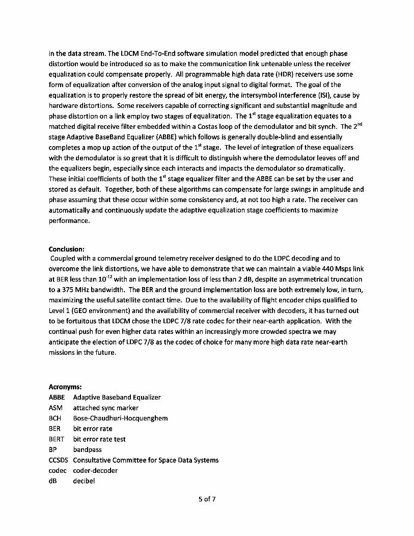
be employed in test. The link spectrum at the input to the receiver in simulation, prior to noise
3 of 7
injection, is displayed in figure 5. To within the uncertainties of both the hardware and software
simulations, the spectrum as presented to the receiver appears identical in both software and hardware.
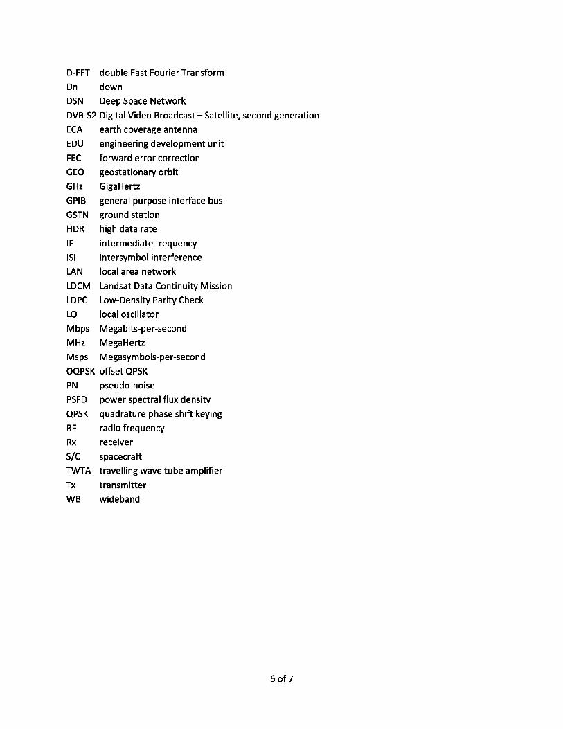
Results of the Software Simulation and Hardware Emulation:
Using the hardware testbench as described above, we are
able to demonstrate (figure 6) that a 7/8 rate LDPC encoded,
440 Msps data stream can be filtered with a bandpass of only
375 MHz and still be decoded with a BER of less than 10- 12 .
Moreover, as can be seen from our results, this has been
accomplished with minimal implementation loss, about 1 dB
for the receiver shown here, and < 1.8 dB for other receivers
tested. These observations indicate the link will function
properly as presently designed and will meet the LDCM
requirements. As a sidenote, the software simulation tended
to be much more pessimistic than the hardware testbench.
However, both the hardware and software properly
emphasized that the success of the mission will rely critically
upon the performance of the signal equalizer in the ground
receiver. Both software and hardware have also indicated a
particular sensitivity to the proper construction of the 1 st
stage equalizer filter, referred to by some receiver
manufacturers as the receiver’s matched filter. This filter is
separate and distinct from the frontend filter. The frontend
analog filter serves as an anti-aliasing filter for digital
receivers. The 1st stage equalizer filter is synthesized totally in
software and occurs after the conversion of the incoming
signal from analog to digital. When dual equalizers are used,
they may not both be adaptive. At least for one
manufacturer’s receiver we have developed a procedure to
derive the coefficients of the matched filter by directly using
the received input signal. Rather than having to anticipate any
change in the communication link due to spacecraft
component aging (or, for that matter, any reason), we simply
“recalibrate” by regenerating the coefficients of the matched
filter, then keeping them fixed.
Equalization:
The spacecraft filter is designed to truncate the bandwidth of
the modulated spectrum prior to transmission so as not to
violate the LDCM spectrum allocation adjacent to the DSN
band. As discussed above, an undesired effect of the filter is
that it introduces significant amplitude and phase distortion
4 of 7
in the data stream. The LDCM End-To-End software simulation model predicted that enough phase
distortion would be introduced so as to make the communication link untenable unless the receiver
equalization could compensate properly. All programmable high data rate (HDR) receivers use some
form of equalization after conversion of the analog input signal to digital format. The goal of the
equalization is to properly restore the spread of bit energy, the intersymbol interference (ISI), cause by
hardware distortions. Some receivers capable of correcting significant and substantial magnitude and
phase distortion on a link employ two stages of equalization. The 1st stage equalization equates to a
matched digital receive filter embedded within a Costas loop of the demodulator and bit synch. The 2 nd
stage Adaptive BaseBand Equalizer (ABBE) which follows is generally double-blind and essentially
completes a mop up action of the output of the 1st stage. The level of integration of these equalizers
with the demodulator is so great that it is difficult to distinguish where the demodulator leaves off and
the equalizers begin, especially since each interacts and impacts the demodulator so dramatically.
These initial coefficients of both the 1 st stage equalizer filter and the ABBE can be set by the user and
stored as default. Together, both of these algorithms can compensate for large swings in amplitude and
phase assuming that these occur within some consistency and, at not too high a rate. The receiver can
automatically and continuously update the adaptive equalization stage coefficients to maximize
performance.
Conclusion:
Coupled with a commercial ground telemetry receiver designed to do the LDPC decoding and to
overcome the link distortions, we have able to demonstrate that we can maintain a viable 440 Msps link
at BER less than 10 -12 with an implementation loss of less than 2 dB, despite an asymmetrical truncation
to a 375 MHz bandwidth. The BER and the ground implementation loss are both extremely low, in turn,
maximizing the useful satellite contact time. Due to the availability of flight encoder chips qualified to
Level 1 (GEO environment) and the availability of commercial receiver with decoders, it has turned out
to be fortuitous that LDCM chose the LDPC 7/8 rate codec for their near-earth application. With the
continual push for even higher data rates within an increasingly more crowded spectra we may
anticipate the election of LDPC 7/8 as the codec of choice for many more high data rate near-earth
missions in the future.
Acronyms:
ABBE Adaptive Baseband Equalizer
ASM attached sync marker
BCH Bose-Chaudhuri-Hocquenghem
BER bit error rate
BERT bit error rate test
BP bandpass
CCSDS Consultative Committee for Space Data Systems
codec coder-decoder
dB decibel
5 of 7
D-FFT double Fast Fourier Transform
Dn down
DSN Deep Space Network
DVB-S2 Digital Video Broadcast – Satellite, second generation
ECA earth coverage antenna
EDU engineering development unit
FEC forward error correction
GEO geostationary orbit
GHz GigaHertz
GPIB general purpose interface bus
GSTN ground station
HDR high data rate
IF intermediate frequency
ISI intersymbol interference
LAN local area network
LDCM Landsat Data Continuity Mission
LDPC Low-Density Parity Check
LO local oscillator
Mbps Megabits-per-second
MHz MegaHertz
Msps Megasymbols-per-second
OQPSK offset QPSK
PN pseudo-noise
PSFD power spectral flux density
QPSK quadrature phase shift keying
RF radio frequency
Rx receiver
S/C spacecraft
TWTA travelling wave tube amplifier
Tx transmitter
WB wideband
6 of 7
References:[1]R. G. Gallager, “Low-density parity-check codes,” IRE Trans. Inform. Theory, vol. IT-8, pp. 21-28, Jan.1962.[2]Y. Kou, S. Lin and M.Fossorier, ”Low density parity-check codes based on finite geometries: arediscovery and new results,” IEEE Trans. Information Theory, vol. 47, pp. 2711-2736, Nov. 2001.[3]W. Fong, “White Paper for Low Density Parity Check (LDPC) Codes for CCSDS Channel Coding BlueBook,” CCSDS Panel 1B Meeting Paper, Sept. 2002.[4] G.P. Calzolari and E. Vassalo, ” Combined Advanced Coding & Modulation for Future CCSDS High-Rate
Missions”, SpaceOps 2006, 19-23 June, Rome, taly.
7 of 7