Embed Size (px)
Citation preview
Report No. RR
LL-71
Copy No.
Land Locomotion LaboratoryResearch Division
Research and Engineering Directorate
THE MECHANICS OF WALKING VEHICLES
__ ~~by B1N
Joseph E. Shigley
September 1960
Project No. ___Authenticated:
D/A Project No.
U. S. Army Ordnance Tank-Automotive Command1501 Beard
Detroit 9, Michigan
a00.gT09
TAPLU O" CCiThNTS
Pago
APSTRACT iiFOREWORD iiiACKNOIE DC1,,NT viLIST OF SYT10OLS viiLIST OF FICURES viii.LIST OF TAPLES x
1. INTRODUCTION I
1-1. Definitions and Nomenclature 11-2. Requirements of a Whlkinf Mechanism 21-3. Scope of the Investigation 3
2. ECHIANICS OF THE FOOT 5
2-1. Locus Relative to Vehicle 52-2. Velocity and Motion Considerations 72-3. The Feet and Shoes ii2-b. Skis or Runners 132-5. Balancing 13
3. N.CHANICALLY OMERATED IJALKINO MECI AKNJSNS 17
3-1. Objectives and kethods of Attack 173-2. Solutions 193-3. Performance 253-h. Dynamic Analysis of tic Ca'-grcove Mechanism 26
Dynamic Analysis of Ihe Doulle-rocker 1 ecLan.sm(Figure 3-5)
4. HYDRAULICALIY OFERATED WALKIN( MEClANl1St'S 41
L-i. Descriplion i4-2. Dynamic Analysis of' the Pawilograph Mechanism h44-3. Control System for Pantopraph Legs 57b-b. Performance of the Pantograph Vehicle 59
BIBLIOGRAPHY 60
i

ABSTRACT
It is well known that animals can travel over rough
terrain at speeds much greater than those possible with
wheeled or tracked vehicles. Even a human being, by "getting
down on all fours" if necessary, can travel or climb over
terrain which is impossible for a wheeled or tracked vehicle.
Nature, apparently, has no use for the wheel. It is there-
fore of considerable interest to learn what machines for land
locomotion can do if they are designed to imitate nature.
Accordingly, it is the purpose of this investigation to
initiate the science of walking and crawling machines.
Specifically, to define the terminology, discover the laws of
walking, and find what manner of mechanisms can be useful.
Another purpose is to study the feet of walking vehicles and
to learn what requiremnts govern their shape and action. It
will also be exceeding-ly useful to discover the speeds with
which walking vehicles can operate, and how these speeds com-
pare with wheeled and tracked vehicle speeds. Finally, all
vehicles must be controlled - by a human or other means.
Therefore it is necessary to investigate methods of control-
ling such vehicles.
ii
F-OREWORD
GENERAL
The disadvantages of a mechanical walking linkage, that is, one drivenfrom a rotating power source, may be summarized as follows:
1. The driving crank must rotate at a non-uniform angular velocityin order to produce uniform vehicle velocity.
2. The length of stride and height of step are fixed.
3. The inertia forces in the horizontal and vertical directions, andthe inertia torques, cannot be balanced satisfactorily.
4. The height of the body above the roadway cannot be controlled bythe operator.
These disadvantages apply only to the mechanisms studied in this in-
vestigation. The possibility cannot be ruled out that a mechanical linkagecould be found which does not have these disadvantages. Nevertheless, such
a possibility seems very remote.
The hydraulic mechanisms, and the pantograph mechanism in particular,overcome all of these disadvantages.
In the analysis of the pantograph mechanism of the previous chapterit was shown that a walking machine should employ 16 legs in gangs of 4each, mounted at the four corners of the vehicle in order to obtain bal-
anced inertia forces and torques and continuously support the vehicle. It
is noted that three gangs of 4 legs each, symmetrically mounted, would sup-port the vehicle, but the inertia forces and torques would not be balanced.
Using, say, six or eight gangs of 4 legs each, half on each side bf the ve-hicle, would obtain balance. However, over rough terrain, and with stiff-
legged vehicles, some of the legs would not be supporting the vehicle,
since they would be "up in the air," and would be simply going along for
the ride. For this reason. it does not seem desirable to go to more than.
16 legs.
There is a good possibility that a control system for a pantograph-
legged vehicle can. be found which will make it possible for the vehicle towalk in a crouch. That is, a descending foot encountering higher ground
could be made to sense this fact and signal the lift cylinder to cease its
lil

downward motion.,at th point. This would make possible a smooth and levelride over rough:terrain, ard consequent higher spieeds. If such a controlsystem can be devised, ihen.more than 16 legs could be used if found desir-able. However, if thevehicle size is fixed, employing more than 16 legsmay require smaller mechanisms end hence a smaller maximum step height andstride length .
We have seen that all walking machines must have shoes which permitrelative motion beteen the shoe ad the terrain, or between the shoe andthe foot. Walking in muck or muddy soil would not permit relative motionbetween the shoe and the terrain., Consequently the shoes or feet must bedesigned to permit reitive motion between them and their point of attach-ment to the walking mechanism.
SUMMARY
This investigation has shown that hydraulically operated walking ma-chines are feasible; that the energy used-by the system is zero over a com-plete cycle if friction is neglected; and that the speed of such machinesover rough terrain, is probably somewhatmore than for wheeled vehicles.
The overall confguitation of a control system has been described whichmakes it possible to control the stride length, step height, speed, and di-rection of motion . ..
The requirements for the desig of the shoes or feet of such a vehiclehave been defined.
In addition, 'eithds of synthesizing the locus or path of the footrelative to the vehidle have been described, and these methods yield thevelocities and accelerations directly .
The basic geometry for a walking vehicle having legs driven by a ro-tating crank has been described: and -the mechanism partially analyzed. Theenergy required t6 dperate mach a vehicle over a complete cycle is zero iffriction is neglected. The jiertia forces for such a vehicle, however,cannot be balanced.' This meanis that such vehicles are potentially usefulonly for very slow speeds. Uless many legs are used, a very large fly-wheel is necessary if the net energy output il to be zero.
A method of sythesizing the non-circular gears required to drive therotating~crank mehanisms has been presented. Also, the principles to befollowed in defining the number of legs,: and in phasing these legs to ob-tain minimum inertia forces and torques, have been stated.
iv..

REC MENDAT !O.S
It is conceivable that the design and construction of a walking ma-.
chine could be initiated at this time° However, many unsolved problems
remain, and the probability of success of such a vehicle, without further,
investigation and development, is small. For this reason a research and
development program should be organized in order to solve the following
problems:
1. The feet and shoes. Is it better to employ skis or runners, or
individual feet? What is the exact geometry? What material or materials
shall be used? What are the dimensions? How are the feet fastened to the
linkage? How much relative motion must they permit, and how is this ac-
complished?
2. The linkage. What is the shape, size, dimensions, and materials?
What kind of bearings shall be employed? What is size and weight of the
various members in relation to the size of the vehicle to be supported by
them?
3. What kind of vehicle suspension system shall be used?
4. The cylinders. How should they be connected to the linkage and
to the vehicle? What size are they?
5. How shall the linkages be ganged? What are the actual mechanicaldetails, including parts, materials, and dimensions?
6. The control system. Must it employ servos? Or can satisfactory
performance be obtained by cam-driven flow-control valves? What is the
exact configuration of the three-dimensional cams and how shall they be
designed? What does the operator actually manipulate in controlling the
vehicle-levers, wheels, push buttons, dials, or what?
7. The hydraulic system. What must be its capacity and pressure?
How can the accumulator be designed? Where, on the vehicle, should thehydraulic elements be placed? What energy losses are involved?
8. What are the fuel requirements for such a vehicle and what mileage
can be expected from it?
9. Can a control system be devised which will sense the operation of
the feet and adjust the operation of the lift cylinders to maintain a con-
tinuously level ride? If so, what effect will bumps and rough places in
the roadway now have on the balance of the legs?
V

The inlvestigatUQfl ri djtateo by, the Iand Locomnot ion Researcoh Branch,Research and bw.1ie un D±u !COrna~e Tank~-Automotive Command.
VI

LIST OF SYMBOLS
A = acceleration, fps2
Ax = = component of acceleration in x direction, fps 2
C = circumference, ft or in.
F = force, lb
Fc = component of force in x direction,. lb
I = mass moment of inertia, lb-sec2 -ft
K = a constant
M = moment of a force, ft-lb
m = mass, lb-sec2/ft
r = radius or length, ft or in.
P = an external force, lb
R = reaction force, lb
T = torque, ft-lb
t = time, sec
V = velocity, fps
,x = k = component of velocity in x direction, fps
x = distance along a horizontal axis, ft
y = distance along a vertical axis, ft
o = the angle between a link or vector and a reference axis
= w = angular velocity, rad/sec
= a angular acceleration, rad/sec2
T = period, or duration of a cycle, sec
vii

LIST OF FIGURES
Figure Page.
1-1 Blockc diagram or, aL walking vehicle..1
:1-2 Locus or theft. 5
2-R Foot lo0i. 6
. 2-3 Definition ot, rock angle, and pressure angle. 8
.2-44 Relative vliolty. diagam. 9
2-5 Comparion of a wheel and a foot. 10
2-6 (a) Shoe on hil ,td'springs; (b) shoe Is an inflated rubbertire) bellows ubaped for greater shear deflection. 12
2-7 Equivalent meo0hanism., 13
3-1 Desired linkage. 18
3-2 A fair-bar Valking linkage. .20
3-3 The cpn-grooyer 22kae
3-4+ A corrected cam-groove linkage. 23
3-.5 -The double-r'okr mechanism. 24
3-6 Dimensions of the" doublk-oke mechanism. 31
3-7 BSnthesia.,of non-cirlcular lgears'. 33
3-8 Non-circulapr 8ears. 34
3-9 Aooelerationmtime diagrm. 37
3-10 Forces on the vehi~cle. 39
4-1 A hydfraulic wlkings linge,. 11
viii

LIST OF FIGURES (Concluded)
Figure Page
4-2 A two-cylinder walking linkage. 42
4-3 Improved model. 43
4-4 The pantograph mechanism. 45
4-5 Forces on the pantograph mechanism. 46
4-6 Inertia torque on the pantograph mechanism. 48
4-7 Nomenclature. 49
4-8 Force-displacement diagram. 55
4-9 Block diagram of control system.' 58
Ix

LIST OF TABLES
Table Page
3-1 Crank Velocity and Acceleration. 27
3-2 Results of Dynamic Analysis of Mechanism.of Fig. 3-4 28
3-3 Digital Computer Analysis 30
3-4 Data for Non-circUila Gears 32
3-5 Accelerations of the Doule-rocker Mechanism 36
4-i Dynamics During Stride- 48
4-2 Kinematic Relations During Lift 52
4-3 Dynamic Relations During Lift 5.3
4-4 Dynamic Relations During Return 53
4-5 Inertia Forces' on Cylindera for One Leg for One Cycle 54
4-6 Summation of Cylinder Forces 56
4-7. Tabulation of Total Inertia Torques for Four Legs and for 56
Eight Legs
x

1. INTRODUCTION
1-1. DEFINITIONS AND NOMENCLATURE
This investigation has for its purpose a study of the feasibility of
utilizing walking, or crawling, machines for land locomotion. In parti-
cular, the study is aimed at discovering some of the capabilities and lim-
itations of walking vehicles as well as the general configuration, control
system, and power-supply requirements and characteristics of such vehicles.
CONTROLSYS>TEM
I i
POWER
S0URCE
ENERGY
5TORAGE
WALKING MECHANISMS
Fig. 1-1. Block diagram of a walking vehicle.
1

The elements of a walking vehicle are illustrated by the block dia-gram of Fig. 1-1. The power source is used to overcome friction be-tween the feet of the vehicle and the terrain, to make up for frictionallosses which occur in the moving parts, and to lift the vehicle overobstructions and up grades. The control system provides a means of con-trolling the speed, direction, length of stride, height of step, andelevation of vehicle above the mean terrain level. The legs or theunit means of locom~tion.are defined as walking mechanisms, in this re-port, and are identified by the numbered blocks in Fig. 1-1. The energy-storage device serves to level the power requirements by providing en-ergy for acceleration of some of the walking mechanisms and absorbingthe energy released by the deceleration of other mechanisms.
1-2. REQUIREMENTS OF A WALKING ECHANISM
An ideal walking mechanism is one which fulfills the following re-quirements:
1. It must have a uniform velocity while the feet are in contactwith the terrain.
2. The stride must be long in relation tq the physical dimensionsof the walking mechanism.
3. The length of the stride must be controllable by the vehicleoperator.
4. The height of the step (return stroke of foot) should be largecompared with the dimensions of the walking mechanism.
5. The height of the step should be controllable by the vehicleoperator.
6. It should have a high stride-time to return-time ratio. Thismeans that the foot should be in contact with the terrain during a majorportion of a cycle of operation.
7. The speed of a walking mechanfam should be capable of variationindependently of other walking mechanisms on the same vehicle. Thisrequirement provides the means for direction control.
8. The walking mechanism should be such that it can move thevehicle in either the forward or the backward direction.
2
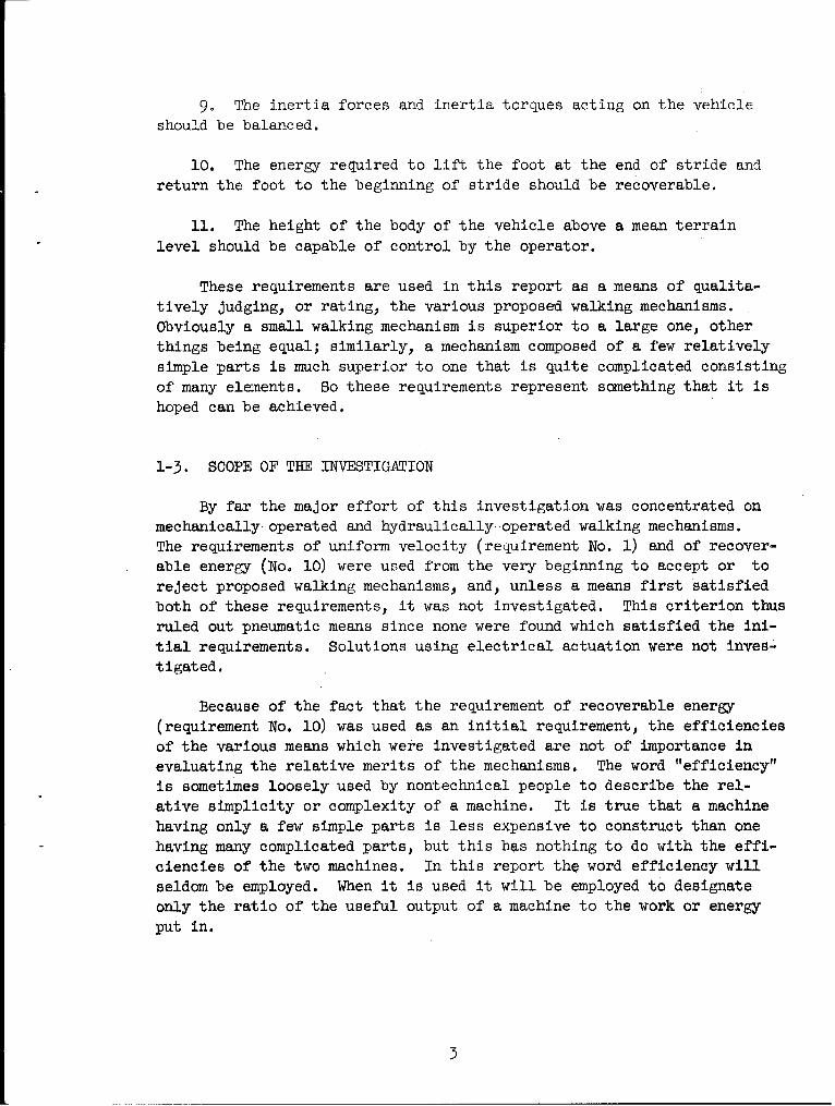
9. The inertia forces and inertia torques acting on the vehicle
should be balanced.
10. The energy required to lift the foot at the end of stride and
return the foot to the beginning of stride should be recoverable.
11. The height of the body of the vehicle above a mean terrain
level should be capable of control by the operator.
These requirements are used in this report as a means of qualita-
tively judging, or rating, the various proposed walking mechanisms.
Obviously a small walking mechanism is superior to a large one, other
things being equal; similarly, a mechanism composed of a few relatively
simple parts is much superior to one that is quite complicated consisting
of many elements. So these requirements represent something that it is
hoped can be achieved.
1-3. SCOPE OF THE INVESTIGATION
By far the major effort of this investigation was concentrated on
mechanically operated and hydraulically operated walking mechanisms.
The requirements of uniform velocity (requirement No. 1) and of recover-
able energy (No. 10) were used from the very beginning to accept or to
reject proposed walking mechanisms, and, unless a means first satisfied
both of these requirements, it was not investigated. This criterion thus
ruled out pneumatic means since none were found which satisfied the ini-
tial requirements. Solutions using electrical actuation were not izves-.
tigated.
Because of the fact that the requirement of recoverable energy
(requirement No. 10) was used as an initial requirement, the efficiencies
of the various means which were investigated are not of importance in
evaluating the relative merits of the mechanisms. The word "efficiency"
is sometimes loosely used by nontechnical people to describe the rel-
ative simplicity or complexity of a machine. It is true that a machinehaving only a few simple parts is less expensive to construct than one
having many complicated parts, but this has nothing to do with the effi-
ciencies of the two machines. In this report the word efficiency will
seldom be employed. When it is used it will be employed to designate
only the ratio of the useful output of a machine to the work or energy
put in.
3

A study of foot iioti:'Isha -ths, e!path of and characteristicsof the motion of the foot relative to the terrain, is necessary inorder that the geometry and the laws governing the action of the footcan be defined. The results of such a study are included in this re-port. Also included are the laws governing 'the number of legs andtheir arrangement.
A walking machine should be capable of going around or over anddown hills, across ditches, tinder bridges, and around obstructions.
Consequently it is necessary to control the speed and direction of mo-tion of such vehicles. It is also necessary to control the length andheight of the foot motion. For this reason an investigation of the con-trol systems is a necessary part of this report.
Under the assUMption that walking vehicles will have unique advan-tages over wheeled vehicles, a group of recommendations for furtherstudy and investigation have been included. An expression of these ad-vantages has not been included because this would necessarily entail astudy of wheeled vehicles for proper comparison. Such a comparison istherefore left to others.
14

2. MECHANICS OF THE7 FOOT
2-1. LOCUS RELATIVE TO VEHICLE
A useful means of obtaining a preliminary estimate of the value of
proposed walking mechanisms is to graphically generate the closed curve,
called the locus, which contains all positions of a given point on the
foot. In generating this curve the vehicle is imagined to be stationary,
and the terrain or roadway to be moving backward at the vehicle velocity.
• C
HEIGHT
OF 5TEP
DRIVE
A 'STRIDE B
Fig. 2-1. Locus of the foot.
Figure 2-1 illustrates a typical locus. The distance AB is the stride;
this line should be straight and a point traversing this portion of the locus
should move at a constant velocity. The remaining portion of the curve BCA
constitutes the lift. return, and lower phases of the cycle. The shape of
the lift and lower portions of the curve is useful in determining the action
of the foot in initial and final contact with the terrain. The shape of the
return portion of the curve is immaterial except as it affects the peak
acceleration of the cycle.
5

cc)
Fig. 2-2. Foot loci.
Figure 2-2 illustrates a group of paths. A point traveling on thecircle of Fig. 2-2a with uniform velocity would have a minimum acceleration,but the length of stride would be infinitely small. In fact this illus-trates that a wheel may be classified as a special case of a walkingmechanism.
6

The rectangular locus of b offers distinct advantages. It gets the
foot off the ground quickly and in the most direct manner at the end of
stride and replaces the foot in the same manner at the beginning of stride.
But time is required for the lower phase of the action as well as for the
drive phase. If the foot should encounter the roadway before the lowerphase is completed the vehicle would either pause for the remaining in-
terval, or sliding would occur. Furthermore where velocities are at all
appreciable a locus having corners is abhored by nature. The result
would be infinitely large accelerations resulting in unsatisfactory per-
formance and life.
The loci of Fig. 2-2c and d represent paths which can be generatedby four-bar linkages. In some cases a loop exists at the pointed end.
Unsatisfactory performance may be expected from both of these because ofthe high accelerations at the pointed ends, and because of the manner
in which the foot contacts or finishes contact with the roadway at the
pointed ends.
This discussion is intended to demonstrate that the locus of Fig.
2-2e is an ideal one. It has a long, straight, stride. The return por-
tion of the locus is direct, and promises to give minimum accelerations.
The lift and lower phases of the action resemble that of a wheel and
should have acceleration characteristics not too different from a wheel.
Furthermore, if the locus is symmetrical about both horizontal and ver-
tical center lines, then the possibility exists of getting balanced
inertia forces by properly phasing a number of w~lking mechanisms on
like paths. If the path is symmetrical then vehicle reversibility is no
problem. And finally, the shape of the lift and lower phases seems to
be the best compromise between the circular locus of a and the rectangular
one of b.
2-2. VELOCITY AND MOTION CONSIDERATIONS
In the case of a wheeled vehicle the tread of the wheel contacts
all particles of the roadway along the path of travel. But the shoe of
a walking vehicle contacts only spots or small areas along the path of
travel. The next spot of contact may be at a higher, a lower, or at
the same relative elevation, as the preceding one. Consequently it is
necessary to investigate the action of the shoe during the lower and
lift phases as well as during the stride phase of the action.
7

Another factor of' importance concerns the foot, or leg, or member towhich the shoe is ataikhed. Just "as the leg of a horse or a 'human beingassumes a number of attitudes relative to the ground during stride, so also
does the leg of a walking machine. In all cases investigated the leg hada rocking motion relative to the terrain during stride. The angle of thisrock and the relative location of this angle varies considerably with dif-
ferent mechanisms. In some mechanisms the rock is with the direction of
travel; in others it is against the direction of travel; and there are
even some mechanisms in which the leg rocks in both directions duringstride. The magnitude of this angle affects the size of the shoe and the
variation of the leg forces. The relative location of the rock angle
influences the magnitude of the leg forces.
The meaniag of rock l and pressure angle as used in this reportis illustrated in Fig. 2-3. As shown, the pressure angle varies duringstride, and the rock angle is simply the difference between the maximumand minimum pressure angles.
ROCK ANGLE
VEHICLE MOTIONPSUEMINIMUMAN16I_
PRE361MR ANSI. EXTREME POSIToK~OF LeC7
Fig. 2-3. Definition of rock angle and pressure angle.
One might specify that the difference between walking and crawling is
essentially in the height of step used. Thus a machine can be said to"walk" when the height of step is large, and to "crawl" when the stepheight is small. Having made this distinction one might reason from Fig.
2-3 that crawling machines should have low pressure angles and low rockangles, and that such machines would be useful for climbing relatively
smooth steep grades. On the other hand it is doubtful if a constantly
small pressure angle can be associated with a "high-stepping" machine,and consequently, walking machines should be most useful over rough terrainof moderate grade. All of these conclusions are based primarily on the
8

leg forces. Thus wp would prefer a leg which is always in pure compression.
Later we shall discover that this is seldom true and that bending forces
exist in the legs because of the static weight of the vehicle and because
of the acceleration forces.
One can write the relative velocity equation in the form
= VVT + VFV (2-1)
which states that the velocity of the foot relative to the terrain equals
the velocity of the vehicle relative to the terrain plus the velocity of the
foot relative to the vehicle. Equation (2-1) is a vector relationship.
During stride VFT = 0 and we have
VFV = -
which means that the foot moves backwards relative to the vehicle but at
the same velocity as the vehicle. It is interesting to plot a graph showing
the relationship of the three terms of Eq. (2-1) for all phases of a cycle.
Assuming equal times for the four events and a linear velocity change for
the lift and lower phases, we get the graph of Fig. 2-4. Examining this
g- t
rime
. Dr- -a .LIFT-----,-,RETURN -P LOWER -5TRIDE
Fig. 2-4. Relative velocity diagram.
9

graph we see that the velocity of the foot relative to the terrain VFT
is zero during stride, as it should be. During the return stroke, how-
ever, the foot is moving twice as fast as the vehicle and in the same
direction. Note that, in the first half of lift and the last half of
lower, the foot is moving slower than the vehicle. This means, duringlift, if the foot is still in contact with the terrain, or if it meets
an obstruction and comes into contact again, that the vehicle will pull
or drag the shoe over the terrain. Similarly, during the last half of
lower, relative motion between the shoe and the terrain will occur if
contact is made before the beginning of stride. Relative motion betweenthe shoe and the terrain is much more likely to occur on lower than on
lift. Of course, if the vehicle operator has control over the length of
stride and the height of step, then the possibility exists for him to
step or walk over short obstructions and thus avoid sliding of one shoe.
It is interesting to contrast the operation of a wheel when meeting
an obstruction with that of the foot of a walking machine upon meetingthe same obstruction. Both cases are shown in Fig. 2-5. In a a wheeled
vehicle moving with a velocity V meets with an obstruction. Point A isthe point of contact and the periphery of the wheel has the same velocity
V but its horizontal component Vh is less than V and consequently thevehicle instantaneously (except for the elasticity of the tire) tries tochange its velocity to Vh causing shock to the vehicle.- In b the walking
V ,
000
A S iH06 ',
(k)WHrEL Mb)WALIM6l MUC~iANISM
Fig. 2-5. Comparison of a wheel and~ a foot.
10

machine meets the same obstruction. The velocity of the foot Vh also
differs from the velocity of the vehicle V so that the same conditions
prevail velocitywise. The wheel is not capable of sliding until it has
overcome the obstruction. Sometimes the foot will not slide either, but,
in general, it seems that some sliding will generally take place and ease
the shock. Though it is impossible to quantitatively evaluate the dif-
ferences except by actual experimentation, it would appear that properly
designed shoes and feet will permit a moderate increase in speed for the
walking vehicle.
2-3. THE FEET AND SHOES
The basis for the design of the feet and shoes of a walking vehicle
has been established in the preceding sections. It is clear that shoes
having claws or spikes rigidly attached to the legs would constitute a
most unsatisfactory solution. Penetration into the earth of such mem-
bers would prevent relative motion and greatly increase the shock forces
on the vehicle. On the other hand, if the relative motion always occurs
between the shoe and the foot, or in the foot itself, then there is no
reason why spikes or claws could not be used if the nature of the terrain
justifies them.
Later in this investigation we shall find that wide shoes, in many
cases, greatly increases the width of the vehicle. The effort should
therefore be concentrated in the direction of obtaining relatively nar-
row shoes. This now means that we have the following list of desirable
characteristics to guide us in designing the shoes:
1. They should be narrow.
2. They should be capable of supporting large shear deflections in
the direction of travel. Note that this will greatly reduce, or even
eliminate, the amount of sliding between the shoe and the terrain.
3. They must accommodate the rock angle of the leg.
4. They should be capable of supporting and absorbing shock in
the vertical direction.
These requirements may be difficult to satisfy, Two proposals, to
indicate the general line along which thinking should be encouraged, are
illustrated in Fig. 2-6° The shoe mounted on helical springs satisfies
ll

Fig. 2-6. (a) Shoe on helical springs; (b) shoe
is an inflated rubber tire, bellows shaped for
greater shear deflection.
requirements No. 2 and No. 4 extremely well, but it may have a short life
because of fatigue failure of the springs. There is nothing new about
using an inflated rubber tire as shown in Fig. 2-6b. Some arrangement,
such as the bellows-shaped sides1 must be included so as to cause the
tire to support shear deflections.
12

2-4. SKIS OR RUNNERS
When a pair of legs, on a walking machine) are separated by a rea-
sonable distance and synchronized, then their lower extremities may be
Joined by runners or skis in order to provide a very long narrow shoe.
Such an arrangement should be especially useful for walking over soft
terrain such as snow, swampy ground, or loose sand. The possibility is
noted, however, that the use of two legs in synchronism by its very na-
ture prevents the phasing of one leg relative to another in order to bal-
ance inertial effects.
2-5. BALANCING
In this section we shall try to consider in a preliminary and some-
what nonrigorous manner some of the problems involved in balancing the
inertia forces and torques of a walking vehicle. These are closely re-
lated to the shape of the locus of the foot and so such a study should
be useful later in forecasting the probable success of various proposed
solutions.
Figure 2-7 illustrates an equivalent walking mechanism traversing
the ideal locus of Sec. 2-1. It is called an equivalent walking mech-
B
C, b
?~N7 J4 A 0.PP~77
Fig. 2-7. Equivalent mechanism.
13

anism because we wish it to represent the general class of mechanismscapable of traversing the path abcda. Point A represents the foot andthis is the point that generates the locus. Link 2 represents the leg.Link 3 is a rocking block through which link 2 can slide. The drivingforce must be supplied to point B on the leg, but it is not necessarythat we specify the details for the purpose of this discussion.
For convenience let us visualize point A as traversing the locusat a uniform velocity always tangent to the path. Then, because, thedistance OA is always changing, the leg will always have an angular ac-celeration. This will be clockwise part of the time and counterclock-wise part of the time, but the acceleration will exist, except when itis changing direction, for the entire cycle. In addition to the angularacceleration, a vertical acceleration takes place during the lift andlower phases of the action.
For the problem as described, the vertical acceleration during lifthas a sense which is exactly opposite to the vertical acceleration duringthe lower phase of the action. This means that, if two legs on a vehicleare out of phase by one-half a period, then, during the lift and lowerphases of the action, the vertical inertia forces will be exactly oppositein direction. If the masses of the two legs are the same, and if thelines of action of the two inertia forces are coincident, then the re-suiting inertia force on the vehicle is zero. This explains the meaninigof balancing and how the vertical inertia forces can be balanced.
To summarize: Tho vertical inertia forces on a walking vehicle arebalanced if (1) each pair of legs have their action separated in phase byone half a period, (2) the lines of action of the vertical inertia forcesare coincident, and (3) the loci of the feet are identical and are s m-metrical about horizontal and vertical center lines.
Next, we consider the horizontal components of the inertia forces.If the leg is statically balanced these result in an inertia torque andit is in this torque that our interest lies. It is clear, from Fig. 2-7,that the inertia forces during stride will be opposite in direction tothose which occur during the return phase of the action. It is not soclear that their magnitudes will be different. During lift of the legthe mass center changes its position too. Furthermore the angular accel-eration of the leg is different in magnitude during return than it isduring stride because the foot A is closer to the center of rotation 0.Thus a pair of legs separated by a phase of one-half period will onlyhave their inertia torques partly balanced during the stride and returnevents. We shall see, in later portions of this report, how, by using16 or more legs, the inertia torque reaction on the entire vehicle canbe made very small.
14

The preceding discussion shows that two legs are not sufficient to
support one corner of a vehicle if the ideal locus is used and if the
foot traverses this locus with urform velocity. In fact, four legs per
corner separated in phase by one-quarter period would be required for
the vehicle of this discussion.
15
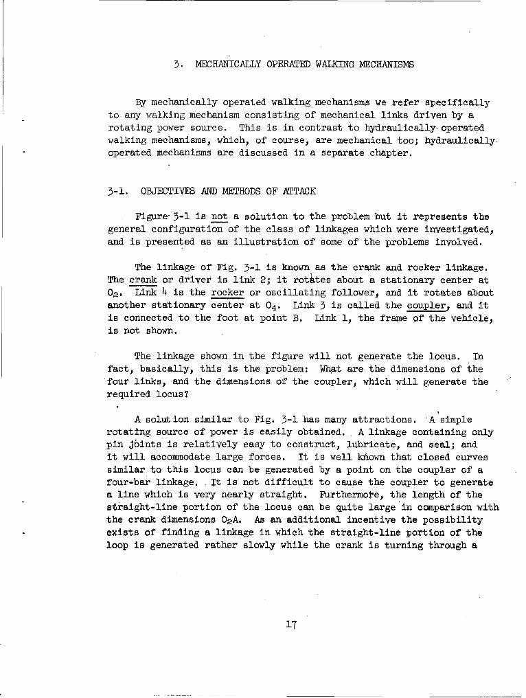
5. MECHANICALLY OPERATED WALKING MECHANISMS
By mechanically operated walking mechanisms we refer specifically
to any walking mechanism consisting of mechanical links driven by arotating power source. This is in contrast to hydraulically, operated
walking mechanisms, which, of course, are mechanical too; hydraulically.
operated mechanisms are discussed in a separate chapter.
3-1. OBJECTIVES AND METHODS OF ATTACK
Figure- 3-1 is not a solution to the problem but it represents thegeneral configuration of the class of linkages which were investigated,
and is presented as an illustration of some of the problems involved.
The linkage of Fig. 3-1 is known as the crank and rocker linkage.The crank or driver is link 2; it rotates about a stationary center at
02. Link 4 is the rocker or oscillating follower, and it rotates aboutanother stationary center at 04. Link 3 is called the coupler, and itis connected to the foot at point B. Link 1, the frame of the vehicle
is not shown.
The linkage shown in the figure will not generate the locus. In
fact, basically, this is the problem: What are the dimensions of the
four links, and the dimensions of the coupler, which will generate the
required locus?
A solution similar to Fig. 3-1 has many attractions. *A simple
rotating source of power is easily obtained. A linkage containing onlypin jbints is relatively easy to construct, lubricate, and seal; and
it will accommodate large forces. It is well khown that closed curves
similar to this locus can be generated by a point on the coupler of a
four-bar linkage. -It is not difficult to cause the coupler to generate
a line which is very nearly straight. Furthermote, the length of the
straight-line portion of the locus can be quite large in comparison with
the crank dimensions 02 A. As an additional incentive the possibility
exists of finding a linkage in which the straight-line portion of the
loop is generated rather slowly while the crank is turning through a
17

MOTION
,%
• C
- --- ---- ,,
Fig. 3-1. Desired linkage.
major portion (say 60 to 80 per cent) of its total crank angle. Thismeans that the crank may turn through say 2700 during stride and use theremaining angle of 900 for the return events of the cycle. Thus, forslow-speed walking machines where inertia forces are not important con-,siderations, the four-bar linkage holds out the promise of giving avehicle with only a few legs, driven by a simple power source, and havinga long stride. Although there are an infinite number of possible solu-tions to such a problem, the rewards appear to be great. Consequentlya great deal of effort was put into the synthesis of such a linkage.
18
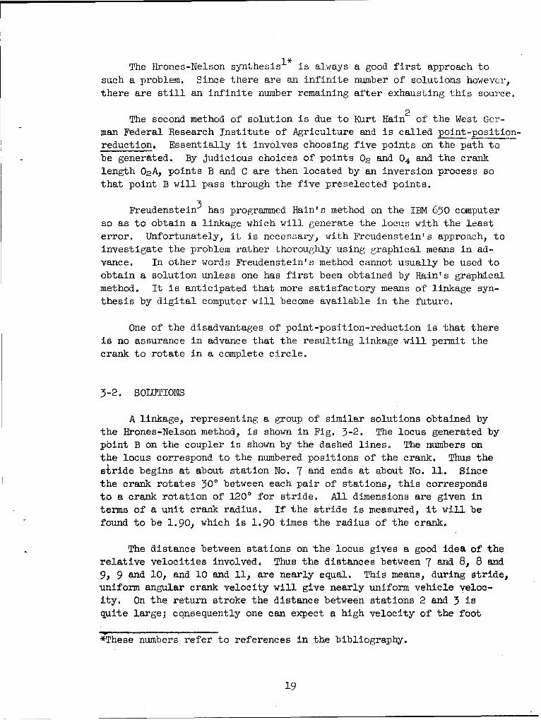
The Hrones-Nelson synthesis I * is always a good first approach to
such a problem. Since there are an infinite number of solutions however,
there are still an infinite number remaining after exhausting this source.
The second method of solution is due to Kurt Hain2 of the West Ger-
man Federal Research Institute of Agriculture and is called point-position-
reduction. Essentially it involves choosing five points on the path to
be generated. By judicious choices of points 02 and 04 and the crank
length 02A, points B and C are then located by an inversion process so
that point B will pass through the five preselected points.
Freudenstein3 has programmed Hain's method on the IBM 650 computerso as to obtain a linkage which will generate the locus with the leasterror. Unfortunately, it is necessary, with Freudenstein's approach, to
investigate the problem rather thoroughly using graphical means in ad-
vance. In other words Freudenstein's method cannot usually be used to
obtain a solution unless one has first been obtained by Hain's graphical
method. It is anticipated that more satisfactory means of linkage syn-
thesis by digital computer will become available in the future.
One of the disadvantages of point-position-reduction is that there
is no assurance in advance that the resulting linkage will permit the
crank to rotate in a complete circle.
3-2. SOLUTIONS
A linkage, representing a group of similar solutions obtained by
the Hrones-Nelson method, is shown in Fig. 3-2. The locus generated by
point B on the coupler is shown by the dashed lines. The numbers on
the locus correspond to the numbered positions of the crank. Thus the
stride begins at about station No. 7 and ends at about No. 11. Since
the crank rotates 300 between each pair of stations, this corresponds
to a crank rotation of 120' for stride. All dimensions are given in
terms of a unit crank radius. If the stride is measured, it will be
found to be 1.90, which is 1.90 times the radius of the crank.
The distance between stations on the locus gives a good idea of therelative velocities involved. Thus the distances between 7 and 8, 8 and9, 9 and 10, and 10 and 11, are nearly equal. This means, during stride,
uniform angular crank velocity will give nearly uniform vehicle veloc-
ity. On the return stroke the distance between stations 2 and 3 isquite large; consequently one can expect a high velocity of the foot
*These numbers refer to references in the bibliography.
19

during this period. On the other hand, at the two ends of the stroke,the velocity is changing magnitude as well as direction quite rapidly.
Therefore we can expect very large accelerations at these ends.
We note also that the return-stroke clearance is only a small frac-tion of the crank radius, and this is most unsatisfactory. The return-stroke clearance can be improved by moving point B to a new position rel-
ative to points A and C, but this always reduces the straight-line por-
tion of the stride.
0
Fig. 5-2. A fair-bar walking linkage.
Another disadvantage of the mechanism of Fig. 3-2 is the fact thatthe bottom of the crank circle is too close to the roadway surface.
20
..... ,.. ......,,: ~i i ... .. ... ... II

Thorough searching of the Hrones and Nelson figures reveals only a
few linkages capable of generating the desired locus. None of these
appear to have any advantages over the one of Fig. 3-2. On the other
hand if link 4 is permitted to oscillate about a point which is near orbelow the roadway surface then a great many configurations become avail-
able for study. Of course, link 4 cannot actually oscillate about a
pivot on the vehicle frame which is located underneath the road; the
same effect may be had simply by causing point C to move on the arc of
a circle whose center is below the road. Thus in order to investigate
this class of linkages we replace link 4 by a slider pivoted at C and
constrained to move on a circle arc whose center may be anywhere.
The existence of a slider pivoted on the coupler may not be a satis-
factory solution because this requires a cam groove for each leg. Such
a groove would be difficult to seal off from mud and dirt on the side of
a vehicle and would require rather elaborate bearings qnd housings.
Nevertheless, the desire to obtain something capable of being analyzed
(whether it is practical or not), coupled with the complete failure of
the point-position-reduction synthesis to yield anything, le4 to an in-
vestigation of four-bar linkages in which the fourth link is a slider
operating in a cam groove.
The linkage of Fig. 3-3 is representative, and among the best, of
the group utilizing a cam groove. The locus shows a good stride, a
fairly good return-stroke clearance, and A lower phase of the action
which is not too bad. The lift phase of the action is not good, and
the locus is not symmetrical about either the vertical or the horizontal
center lines. The fact that the foot velocity during stride is not
uniform requires that the crank be driven at a non-uniform velocity.
This is a correction means and it can be accomplished by utilizing a
pair of non-circular gears. One of these.is connected to the crarn-
shaft and the other acts as a driver.
Certain alterations may be made in the mechanism of Fig. 3-3 inorder to change the shape of the locus. Lengthening BC increases the
return-stroke clearance and causes the stride to become more curved.
Increasing the distance AC generally flattens the locus, sharpens the
ends, and introduces some curvature into the stride. If the center of
curvature of the cam groove is moved further away from the crankshaft,
with no other changes, the entire locus is shifted downward, and the
length of stride is increased.
21

4
0 CA Q*Wvrz
G
0
Od%
S.06 4 RAD.
Fig. 3-3. The cam-groove linkage.
Slight changes in the shape of the locus can also be made by altering
the curvature of the cam groove. Since there is no reason to make this
groove of constant curvature, this is a logical way of refining the locus.
As an example of what can be done, Fig. 3-4 shows a correction which was
made to improve the shape of the lift portion of the locus. Both stations
12 and 1 on the locus are higher due to the corrected groove, and the re-
sulting locus is now improved,
22

4
r 1 CO RRE TED
Cod J. 01-
Fig. 3-4. A corrected cain-groove linkage.
Corrections to the velocity, and even to the acceleration, can also
be made by correcting the cam groove. But, since velocity and accel-
eration are related to position, changing of one of these quantities will
also affect the other two. Consequently, there is a limit to what-can
be done in this direction.
It is clear that the two groups of solutions described thus far
leave much to be desired. The mechanism of Fig. 3-2 represents the gen-eral configuration of the linkage which has been sought, but the locushas a poor shape. The mechanism of Figs. 3-3 and 3-4 represent, probably,the best locus that can be obtained, using a four-bar linkage; but the
existence of the cam groove is a great disadvantage..
It is not at all obvious that the solution to this problem consists
in taking a linkage similar to the one of Fig. 3-3, turning it upsidedown, and connecting another link to point B, having the foot on the op-posite end. Such an arrangement makes possible the selection of a link-
age from a much larger group in the Hrones-Nelson catalogue having much
more satisfactory loci. One of the best of these', although there are
many good ones, was synthesized, according to this idea, and the result
is shown in Fig. 3-5. The basic linkage, as selected from the catalogue,
23

C4t
10
00
40
24

consists of the chassis 1, the crank 2. the coupler 3 containing points
A, B, and C, and the rocker 4. Point C on the coupler is the point to
which we wish to connect the leg. But a leg connected only at C would
not have constrained motion. Consequently, we borrow an idea from the
transport mechanism, add links 5, 7, and 8 to the system, and get a
linkage consisting of 2 feet M and N.
If we examine the loci traced out by the feet we find that the
stride takes place during 210' of crank rotation, thus accomplishing the
objective of getting a stride which occupies a major portion of the crank
angle. In addition, the length of stride is 3-1/2 times the crank radius,
which is very good. The spacing of the station numbers indicates that
some velocity correction is necessary during stride, but this is no worse
than any of the other linkages studied. The symmetry of the locus is
about as good as one can expect to obtain with any linkage driven by a
rotating crank. A higher return-stroke clearance can be obtained by
slight alterations in the dimensions of the members, but this is obtained
at the expense of the stride.
3-3. PERFORMANCE
In this section we shall discuss the performance of each of the
three walking mechanisms in terms of how well they satisfy the require-
ments of Sec. 1-2. The numbers which follow identify the particular
requirements of that section.
1. None of the three mechanisms described fulfill the uniform veloc-
ity requirement. They can all be made to do so by driving the cranks at
non-uniform velocities using pairs of non-circular gears.
2. None of the strides are very long when compared to the overall
space required by the mechanism. The linkage of Fig. 3-4 does the best
job of satisfying this requirement. The linkage of Fig. 3-5 is not asbad as it appears because we are getting two feet instead of one with it.
5. In all three mechanisms the length of stride is fixed by the
dimensions of the linkage. It cannot be controlled by the operator.
4. The height of step is satisfactory for the mechanisms of Figs.
3-4 and 3-5, but not for the one of Fig. 3-2.
5. In none of the mechanisms is the height of step controllableby the operator.
25

6. The stride-time to return-time ratios are as follows:
Fig. 3-2 Ratio = 0.5Fig. 3-4 Ratio = 0.71
Fig. 3-5 Ratio = 1.4o
A ratio less than unity means that the stride occupies only a small por-tion of the cycle time. A ratio more than unity means that the strideoccupies a major portion of the cycle time. Hence, Fig. 3-5 is superior.
7. If the cranks are driven from the same source of rotating powerand a controlled differential is not employed, then the requirement ofindividual speed variation cannot be met. Using a controlled-differentialarrangement, however, would make it possible to control the speeds of thefeet on opposite sides of the vehicle for direction control.
8. All three mechanisms may be operated in either direction.
9. The inertia-force requirement is an important one requiring con-siderable analysis. The results depend upon the number of mechanismsand their arrangement on the vehicle. This requirement is treated inseparate sections for the mechanisms of Fis. 3-4 and 3-5. The one ofFig. 3-2 is too poor to justify this lengthy analysis.
10. This requirement may be satisfied for each of the three mech.anisms if a flywheel is present in the power source.
,li. In none of the mechanisms is the height of the vehicle bodyabove the terrain controllable by the operator.
In summary, the linkage of Fig. 3-2 can be made to fulfill four ofthe ten requirements discussed here, Fig. 3-4 will satisfy six of them,and Fig. 3-5 can be made to satisfy seven of them.
3-4. DYNAMIC ANALYSIS OF THE CAM-GROOVE MECHANISM
Our purpose in making a dynamic analysis is to obtain an idea ofthe inertia forces resulting from the action of a single mechanism, andthen, by utilizing a number of mechanisms on the same vehicle, discoverif these inertia forces can be balanced by proper phasing or timing ofthe several mechanisms relative to each other. Such an analysis willalso reveal the energy variations which must be handled by the flywheel.
' . .. .. .. .. ... 'I 2 6

Since the methods of making a dynamic analysis are well known, only
the results will be presented. The problem to be analyzed is stated as
follows:
In Fig. 3-4, 02 A = 16 in., AC = 48 in., AB 1 43.2 in., BC = 17.8 in.;radius of cam groove is 64 in. for stations 2 through 11 inclusive, and
6.4 in. for stations 12 and 1; the distance to the center of gravity oflink 3 is 30 in. measured from A, and the weight is assumed to be 30 lb.Assuming this weight to be equally divided between points A, B, and C,
the moment of inertia is 13 = .28 lb-sec2-ft. We shall assume that
crank 2 is balanced and that it has an 12 = 0.70 lb-sec2 -ft. Table 3-1gives the angular velocities and accelerations of the crank for stations
on the stride. This table was obtained by first finding a suitable setof dimensions for a pair of non-circular driving gears for the linkage.The figures given in the table correspond to a vehicle speed of 10 mphwhich was arbitrarily selected. The crank angular velocity for all otherstations is 15.4 rad/sec, and the angular acceleration is zero.
After the design of an actual vehicle has been completed it may be
found that some of these values are somewhat unrealistic. For the ]pur-poses of obtaining values to compare with other vehicles and walkingmechanisms these assumptions are perfectly satisfactory. Furthermoreour prime purpose is to discover if the inertia forces for a vehicleutilizing the walking mechanism of Fig. 3-4 can be balanced, and this
can be done with any group of compatible data.
TABLE 31. CRANK VELOCITY AND ACCELERATION
Angular AngularStation Velocity, Acceleration,
No. rad/sec rad/secP
7 15.4 0
8 12.3 -789 10.9 -17
10 11.1 60
11 15.4 0
The results of this analysis, which is quite lengthy, are tabulatedin Table 3-2. The analysis was carried out for twelve time-equal steps.Results are given for one leg, two legs, and four legs, all mounted at
the same place on the vehicle. In this example, the vehicle must have
sixteen legs (minimum), four at each corner, in order that at least fourfeet be on the ground at all times.
27

TABLE 3-2. RESULTS OF DYNAMIC ANALYSIS OF MECHANISM OF FIG. 3-4
T = inertia torque, ft-lbFx = horizontal component of inertia force, lbY= vertical component of inertia force, lb
Step One Leg _ Two Legs F ur Legs
No. T Fx FY T Fx Fy T Fx FY
I -180 460 190 -225 300 135 -223 80 2502 -175 250 70 -178 200 10 53 45 - 53 - 4o 60 150 -65 15 110 - 14 - 90 -254 158 -150 150 22 -220 115 -223 80 2505 141 -285 60 231 -155 - 15 53 45 - 56 - 32 -275 - 5 51 -105 -135 - 14 - 90 - 25.7 - 45 -16o - 55 -225 300 135 -223 80 2508 - 3 - 50 -60 -178 200 10 53 45 - 59 - 25 - 45 - 40 - 65 15 110 - 14 - 90 - 25
10 -136 - 70 - 35 22 -220 115 -223 80 250
U1 90 130 - 75 231 -155 - 15 53 45 - 512 82 170 -130 51 -105 -135 - 14 - 90 - 25
The results for two legs are obtained from those for one leg by phasingthe two 1800 apart. Those for four legs were obtained by phasing the legs 9b0apart. Data for six legs, equally phased, are not shown, but this can easilybe calculated directly from the table.
It is probable that the peak values of these forces occur somewherein between the steps chosen. Only enough steps were taken to obtain a gen-eral idea of the trend of the curves.
The table shows that the inertia-torque peaks increases as the numberof legs increases. Of course, the integral of the product of the torqueand the differential time is always zero over a complete cycle. The highpeaks mean that a large flywheel is necessary to store the energy.
The component Fx is a force which shakes the vehicle in the forwardand backward directions. This inertia force is reduced a great deal, forthis mechanism, by employing four legs, and it would be reduced more thanthis if six legs were used at each corner.
28

The component Fy is the force that shakes the vehicle in the vertical
direction. The table shows that this force increases as more legs are used.
We can conclude, from this analysis, that the inertia forces cannot be
balanced for the mechanism of Fig. 3-4 and, hence, requirement 9 is not sat-
isfied.
3-5. DYNAMIC ANALYSIS OF THE DOUBLE-ROCKER MECHANISM (FIG. 3-5)
A complete dynamic analysis of the linkage of Fig. 3-5 would involvethe following:
1. Determining the angular velocities and accelerations for all eight
links for 12 crank positions.
2. Calculations of the inertia forces and torques due to each link
and their reactions on each of the other 7 links. This requires the super-
position of 8 calculations for each crank position making a total of 96lengthy calculations.
The calculations indicated in the previous paragraph are not difficult
but they are lengthy and complicated, requiring graphical treatment and the
making of many hundreds of free-body diagrams of the links in their various
positions. Certainly, before proceeding with such a time-consuming project,it is wise to use every resource available to obtain a preliminary estimate
of the probable value of such an analysis.
The first step, in getting this preliminary estimate, was a digital
computer solution of the kinematics of links 3 and 4 of Fig. 3-5 with anangular velocity of Link 2 of 1 rad/sec. The results of this analysis, inincrements of 50 of crank angle, are given in Table 3-3. The size of the
linkage investigated and the nomenclature are illustrated in Fig. 3-6. Theangle @ is measured counterclockwise from the x axis. Thus the crank is
shown in the @ = 0 position. All angular velocitie' and accelerations are
positive in the counterclockwise directiob. The quantities VC andiAC are the
velocity and acceleration of point C, respectively, in units of feet and
seconds. The angles @V and GA are the angles that the velocity and accel-
eration vectors, respectively, make with the x axis.
Examining VC and QVI of this table, it is easy to see that stride begins
about where @ = 71.50 where V0 = 0.73 fps and GV = 188.20 because the footis now nearly on a horizontal course. Similarly, stride ends at about 9 =
j1.50 . Now, if we take a vehicle velocity of 14.7 fps (10 mph) and makeVC equal to this during stride, then the crank angular velocity will have
29

aj% 1 '3 ARA CUHI\-* HC 4 r0 H HIi \ H H4 14 i4 A% fu 0j a- cm
Hi It HC~ ~ % cjO0
0%HCiIt. n .l\-TP\ %XN
*r c! C \Il ' % r u 0 % C0 '0 ow 4P\Cn -t0 L , ? t .
CU HO 4 H 00 0H%' H H0li OH cliC~' t-%O H C H O 0%U'.\
CMH.* A .. R ,C C H U
HHH H- H H\ CU CU . . . . i. C4 % '
KN mW Z: SN g I- mug "P a, W\ A 8 a p a 2 -A St T- I8 A r a
.~~~~ ~ ~ .0% . . . .
Z% ~ ~ 1 11 1 1 1 nH H HH H 4- \IInt\L\ m\wur -\ n n Wwv' fi
*l , ,U OO.C% U I iC 0 Q'. A .) U U )
'A.U CUCI 9UHH HHHH VA0 aA 91oIA
CR a,.VWNI - 0 K 4 1K) a11 11191:1R 711If n 41 O
0 t o'
A' A' A' 8;' Ip' 0I' It' IP' t' I' R' IR I'AI" ' It' at.I' t.U.I" '.I' t.I' I. It'. -A. U'Q ' It' '.I- ppp1*Io* f U ( MrlH r
cmc -#4 t'iil.C HU CUr qr r ir H H i H H
H Ct'0. P %0.S Hl R I. U -A U "U' R ' O d'. -g -- 0 CU 60 e . ..
ID 0c, \0H H 00 0H.- t1
a 00 0- W 'l't' 19 " '00 1"0U' -%% H H or Dci " Ho H. - H 0%o' H -~ It'.Hu 0r ifH n C CUUC CUUUi' I.i' t.K i. ' N.C UC UC UCIt~i~* CU ~ ...............................
glutS30

E. 5 o
6C
02 OA-JG"; A1=?.o"; 0CC,GF=I2.,77T u B
%Gx 04 b:B5Ga, C0=EF= o";
8BD .GE :I7/"' PEC 'i51D ~ .-E--GF Jrm Gor".
o219.04'
013 5 . 4
IGO.,
Fig. 3-6. Dimensions of the double-rocker mechanism.
to be changed to accomplish this. 'The formula is
S14.7 (3-1)VC
where w2 is the crank velocity in rad/sec. Listing crank angles from
71.50 to 251.50 in 10' intervals in Table 3-4, we may calculate the cor-
responding values of a)2 in order to give a vehicle velocity of 14.7 fps.
These values are listed in the second columin.
The next step is to synthesize a pair of non-circular gears which
will give the angular velocities shown in Table 3-4. Designating the
driving gear by the subscript 3 and the driver gear by 2, the following
relationship must hold:
r2w2 = r3ws (3-2)
r2 + r3 = (3-3)
c2 = C3 (3-4)
31

TABLE 3-4. DATA FOR NON-CIRCULAR GEARS
0 r2 rs 2 r2 rs w2
1.5 1.78 2.22 21.2 181.5 2.18 1.82 14.211.5 1.72 2.28 22.6 191.5 2.16 1.84 14.421.5 1.68 2.32 23.4 201.5 2.13 1.87 14.931.5 1.65 2.35 24.2 211.5 2.11 1.89 15.241.5 1.64 2.36 24.4 221.5 2.09 1.91 15.651.5 1.67 2.33 23.7 231.5 1.98 1.96 16.361.5 1.73 2.27 22.3 241.5 1.88 2.02 17.371.5 1.83 2.17 20.2 251.5 1.88 2.12 19a181.5 2.03 1.97 16.5 261.5 1.88 2.12 19.291.5 2.14 1.86 14.7 271.5 1.88 2.12 19.2
101.5 2.21 1.79 13.7 281.5 1.88 2.12 19.2111.5 2.27 1.73 13.0 291.5 1.88 2.12 19.2121.5 2,27 1.73 12.9 301.5 1.88 2.12 19.2131.5 2.27 1.73 12.9 311.5 1.88 2.12 19.2141.5 2.27 1.73 13.0 321.5 1.88 2.12 19.2151.5 2.25 1.75 13.2 331.5 1.88 2.12 19.2161.5 2.23 1.77 13.5 341.5 1.88 2.12 1902171.5 2.20 1.80 13.9 351.5 1.83 2.17 20.2
In these equations r is the instantaneous pitch radius, w the angular velocity,K a constant, and C the circumference. The first equation states that thepitch-line velocities are equal. Equation (3-3) states that the center dis-tance must remain constant. And Eq. (3-4) states that the pitch curves musthave the same circumferences. Solving Eqs. (3-2) and (3-3) simultaneouslyyields-
r 2 K (3-5)
The procedure for Ablving Eq, (3-5) is to decide on a suitable center dis-tance- K, and then to try various values of os (a constant) until Eq. (3-4)is satisfied. This is a graphical solution.
Figure 3-7 shows bow the method works,. Choose a center distance K0203. Guess at a. Calculate r2 equal to 02a, 02b, 02c, etc., correspondingto the desired values of a and lay these off as shown using angular inter-vals, in this case, of 100, The radius rs is the difference between K andr2, so these values may be set on a compass and the arcs 03b', Osc', 03d',etc., laid off. Now, find points on the pitch curve by constructing the
32

03
Fig. 3-7. Synthesis of non-circular gears.
equalities ab = a'b', be = b'c', cd = c'd'. etc. Continue this procedureuntil the entire gear has been traversed. Usually it will be found thatthe guess for w3 is wrong and the pitch curve for gear 3 does not close,or that it overlaps itself. If it does not close, try a larger value for
w3. If it overlaps, try a smaller value.
Using this procedure, the pair of gears shown in Fig. 3-8 were syn-thesized. Since stride occurs between 71.5' and 251.50,these radii arefixed. However, continuing from 251.50, back around to 71.50, we havea curve which can be faired in to suit. The results of this synthesisare given in Table 3-4 together with the values of w2 that result.*
The next step in our analysis is to find the incremental times re-quired for the crank to traverse each 100 increment. We do this by av-eraging the angular velocities at the beginning and end of each interval,and dividing this average velocity into 0.1745 radians, the radian measure
*The Land Locomotion Laboratory of the Detroit Arsenal constructed a pair
of non-circular gears from data obtained by a rough graphical analysis.The computer solution described earlier in this section makes possiblea much more satisfactory solution to this problem. It is believed thatthe pair of gears synthesized here will overcome many of the deficiencieswhich were undoubtedly found in the earlier ones.
33

T-
raz
615
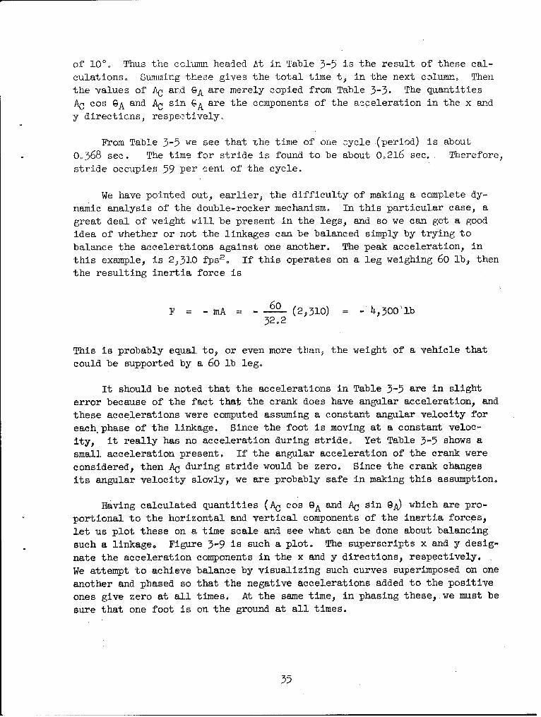
of 100. Thus the cclumn headed At in Table 3-5 is the result of these cal-
culations, Summing these gives the total time t, in the next column. Then
the values of AC and GA are merely copied from Table 3-3. The quantities
AC cos GA and AC sin GA are the components of the acceleration in the x and
y directions, respectively.
From Table 3-5 we see that the time of one 3ycle (period) is about
0.368 sec. The time for stride is found to be about 0.216 sec. Therefore,
stride occupies 59 per cent of the cycle.
We have pointed out, earlier, the difficulty of making a complete dy-
namic analysis of the double-rocker mechanism. In this particular case, a
great deal of weight will be present in the legs, and so we can get a good
idea of whether or not the linkages can. be balanced simply by trying to
balance the accelerations against one another. The peak acceleration, in
this example, is 23.0 fps2. If this operates on a leg weighing 60 lb, then
the resulting inertia force is
F = - mA 6 0 (2,510) = -'4,300'lb32°2
This is probably equal, to, or even more than ,, the weight of a vehicle that
could be supported by a 60 lb leg.
It should be noted that the accelerations in Table 3-5 are in slight
error because of the fact that the crank does have angular acceleration, and
these accelerations were computed assuming a constant angular velocity for
each, phase of the linkage. Since the foot is moving at a constant veloc-
ity, it really has no acceleration during stride, Yet Table 3-5 shows a
small acceleration present. If the angular acceleration of the crank were
considered, then AC during stride would be zero. Since the crank changes
its angular velocity slowly, we are probably safe in making this assumption.
Having calculated quantities (AC cos GA and AC sin @A) which are pro-
portional to the horizontal and vertical components of the inertia forces,
let us plot these on a time scale and see what can be done about balancing
such a linkage. Figure 3-9 is such a plot. The superscripts x and y desig-
nate the acceleration components in the x and y directions, respectively.
We attempt to achieve balance by visualizing such curves superimposed on one
another and phased so that the negative accelerations added to the positive
ones give zero at all times. At the same time, in phasing these, we must be
sure that one foot is on the ground at all times.
35

TABLE 3-5. ACCELERATIONS OF THE DOUBLE-ROCKER MECHANISM
9 UaN dv At t AC 9A AC cos GA AC sin GA
1.5 21.2 0 1,970 202.0 -1,825 - 74011.5 22.6 21.9 0.00797 0.00797 2,510 183.8 -2,300 - 155
21.5 23.4 23.0 0.00759 0.01556 2,230 172.4 -2,210 290
31.5 24.2 23.8 0.00733 0.02289 2,190 165.1 -2,120 56541.5 24.4 24.3 0.00718 0.03007 1,620 161.0 -1,530 530
51.5 23.7 24.1 0.00725 0.03732 1,180 159.3 -1,100 420
61.5 22.3 23.0 0.00759 0.04491 780 159.6 - 730 27071.5 20.2 21.2 0.00823 O.05314 470 161.5 - 445 15081.5 16.5 18.4 0.00948 6.o6262 220 164.7 - 210 60
91.5 14.7 15.6 0.01120 0 . 07382 120 169.0 - u8 23101.5 13.7 14.2 0.01230 .o.08612 60 174.5 - 60 5111.5 13.0 13.4 0.01303 0.09915 30 181.3 - 30 0121.5 12.9 12.9 0.01352 0.11267 lo 194.0 - 10 2131.5 12.9 12.9 0.01352 0.12619 0 350.7 0 0141.5 13.0 13.0 0.01342 0.13961 15 7.9 15 2
151.5 13.2 13.1 0.01333 0.15294 20 14.8 20 5
161.5 13.5 13.4 0.01303 0.16597 25 19.5 24 8
171.5 13.9 13.7 0.01272 0.17869 30 22.3 28 11.1181.5 14.2 14.1 0.01238 0o.19107 30 22.5 28 12191.5 14.4! 14.3 0.01220 0.20327 30 19.0 28 10
201.5 14.9 14.7 0.01187 0.21514 30 ii.6 29 6
211.5 15.2 15.1 0.01154 0.22668 35 3.2 35 0221.. 15.6 15.2 0.01148 0.23816 45 -358.3 45 0231-5 16.3 15.9 0.01098 0.24914 70 358.4 70 0
241.5 17.3 16.8 0.01039 0.25953 lo 2.1 110 0251.5 19.1 18.7 0.00934 0.26887 190 7.5 190 25
261.5 19.2 19.1 0.00913 0.27800 280 12.9 270 60271.5 19.2 19.2 0.00908 0.28708 420 .17.4 400 125
281.5 19.2 19.2 0.00908 0.29616 620 20.4 580 215291.5 19.2 19.2 0.00908 0.30524 920 21.3 855 335301.5 19.2 19.2 0.00908 0.31432 1,400 19.5 1,320 470311.5 19.2 19.2 0.00908 0.32340 1,720 14.1 1,700 420
321.5 19.2 19.2 0.00908 0.33248 1,94o 3.1 1,930 105331.5 19.2 19.2 0.00908 0.34156 1,680 341.3 :1,590 - 540341.5 19.2 19.2 0.00908 0.35064 1,200 294.5 500 -1,090351.5 20.2 19.7 0.00886 0.35950 1,440 234.7 - 830 -1,170361.5 21.2 20.7 0.o0843 0.36793 1,970 202.0 -1,825 - 740
36

U
d I-.
0
4-,
ci,
37)

For example, suppose a two-legged vehicle. Imagine that Fig. 3-9 is
reproduced on a sheet of tracing paper, and that we are making the time axes
coincident and sliding the traced curve along the time axis of Fig. 3-9.We are hunting a place where the negative AXIs and Ay's are opposite thepositive ones. We must also be sure that stride exists continuously. Thelast requirement means that the return stroke of one leg will have to occur
during stride of the other leg. Consequently we can obtain no balancing at
all using two legs.
If we decide to employ four legs, in gangs of two, all mounted on the
same side of the vehicle, but with one gang at the front and the other gang
at the rear, then we can partially balance the x components. If the reargang is phased so that the negative peaks coincide with the positive peaks
of the front gang, then some degree of balance is obtained. It is not com-plete though, because of the shape of the positive and negative curves.
The y components, with this scheme, will not be balanced because the lines
of action are not coincident.
There is no way of phasing legs on opposite sides of the vehicle to
obtain balance of the inertia forces because neither of the components have
coincident lines of action. It is possible, as we shall see later, to phase
the legs on opposite sides of the vehicle to balance the inertia torques.
The lack of a complete analysis, in this example, has prevented the cal-
culation of these torques.
It is clear from this simplified analysis that requirement 9 casnot be
satisfied. It is unnecessary, therefore, to make the complete dynamic
analysis.
3-6. 'VEHICLE GEOMETRY
The phasing of several walking linkages to reduce or eliminate the
shaking and rocking of the vehicle due to the inertis forces and inertia
torques has already been discussed. We are now interested in the arrange-
ment of the mechanisms on the vehicle itself.
Figure 3-10 is a side view of a vehicle having legs (not shown) mounted
at points A and B. If the legs are properly phased, then, at some instantin time, the inertia torque TA will be counterclockwise and the torque TBwill be clockwise. Since a torque vector is a free vector, these torques
will cancel one another, if their magnitudes are equal, regardless of thelocation of points A and B.
38

MOTION
TAA
Fig. 15-10. Forces on the vehicle.
Also shown in the figure are the horizontal components FAX and FBx of
the inertia forces due to the action. Again we see that these forces will
cancel each other, if their magnitudes are equal, and if their elevation
on the vehicle are the same. Other than elevation, the .location of A and
B on the vehicle is not important in order to achieve cancellation.
Finally, examining the vertical components F J and F, we see that
#A B'
these forces form a couple which will tend to rock or oscillate the vehicleabout a horizontal axis through the side of the vehicle. In order toachieve cancellation of the vertical components it is necessary for points
A and B to be coincident.
Thus it is necessary to mount enough properly phased legs at onepoint to balance the vertical components of the inertia forces; and it isnecessary to mount enough properly phased legs on one side of the vehiclein order to balance the inertia torques and the horizontal components ofthe inertia forces. Aside from considerations of support and tractionthese are the guiding principles which must be used in selecting and arrang-ing the legs. A machine employing perfect walking mechanisms would havea minimum of eight legs on each side, four at A and four at B, properlyphased, in order that the resultant inertia forces and torques be zero at
all times.
39

3-7. CONTROL
The stride length and height o step are fixed by the linkage dimensionsfor purely mechanical mechanisms, stnd ionsequently these cannot be controlled.
The speed of walking machines can be controlled in the usual manner asfor wheeled and tracked vehicles.
In order to obtain control of direction, for a single vehicle it is
necessary to employ differentials connecting the driving mechanisms of thelegs on opposite sides of the vehicle, and then slow the action on one siderelative to the other. Only the usual mechanical design problems would beencountered in providing this means.
40

4. HYDRAUIICALY OPERATED WALKING MECHANISMS
4-1. DESCRIPTION
Hydraulic operation was first considered as a means of overcoming
the deficiencies of the mechanisms which were driven by a rotating crank.
We have already seen that these deficiencies include the lack of control
over the height of step, and an imperfect locus resulting in unbalanced
inertia forces. Accordingly, the mechanism of Fig. 4-1 uses a hydraulic
cylinder for proper positioning of the foot during all phases of the ac-
tion. Point C is the foot, link 2 the crank, and link 5 the cylinder.
0
Fig. 4-1. A hydraulic walking linage.
41

The cylinder is pivoted at 05, and the piston is connected to link 4.
Thus, when the piston is stationary relative to the cylinder, links 4 and
5 constitute an equivalent single link which oscillates about 05. Thisthen becomes the same class of linkages as the one of Fig. 3-2.
The addition of the hydraulic cylinder does give control over theheight of step. But the locus generated is very poor and would result in
very high acceleration forces on the vehicle because of the difficulty of
obtaining balance by phasing several mechanisms. Furthermore, the crank
must still rotate at a non-uniform angular velocity. Consequently, we
have not gained anything by taking this step.
If the hydraulic power is going to be available on the vehicle, one
might as well go "whole-hog," and use it both for driving and lifting the
feet. Using one cylinder for driving and another cylinder, attached to
the same mechanism, for lifting, then it ought to be possible to programthe action of the two cylinders to obtain any desired locus. The simplestpossible arrangement of two cylinders to accomplish this purpose is theone shown in Fig. 4-2. Here cylinder 2 is intended to take care of the
driving function, and cylinder 5 the lifting function. By programming orcontrolling the flow to these two cylinders properly, the foot B can bemade to generate the ideal locus. Unfortunately, the driving cylinder andpiston rod are placed in bending by the weight of the vehicle, and so this
is not a good solution.
0% -- --- --- -- ~ --
Fig. 4-2. A two-cylinder walking linkage.
In an attempt to eliminate the bending on the piston rods, the mech-
anism of Fig. 4-3 was devised. Actually, this is one of the best of alarge class of mechanisms in which rigid links are utilized in combinationwith two cylinders. In this figure cylinder 2 is intended to accomplish
the driving function, and cylinder 5 the lifting function. The mechanism
42

- sl0G
Fig. 4-3. Improved model.
is quite versatile. For example, the one of Fig. 4-3 has the piston rodof the driving cylinder connected to rocker 4 between point B and the pivotpoint 04. Thus, the piston motion is less than the length of stride. So,in effect, we are multiplying the piston motion by a number greater thanunity to get the stride length. But, if the piston rod is connected to therocker outside of point B, then we get the reverse, and the piston motionis'now less than the stride.
In addition there is really no need to connect the piston rod of thelifting cylinder at point C. It can be connected to link 7 anywhere be-tween B and C. Thus we can obtain multiplying action for the liftingcylinder too.
We may note that points 04 and 05 of Fig. 4-3 need not be coincident.For example, if 0, is located on the vertical center line of the locus,then the rocking motion of the lift cylinder will be symmetrical aboutthis center line.
One of the difficulties of these two-cylinder mechanisms (Figs. 4-2and 4-3) is that the piston motions for lifting and driving are not in-dependent of each other. For example, if the height of step is made one-fourth of the stride, then a certain set of programs must be used to con-trol the action of the two cylinders. But if the height of step is changed,
43

then a different program for each cylinder must be used. Because of thisdependence it may well be impossible to cause the cylinders to faithfullyreproduce their respective programs. If they do not, the locus becomesmisshapen, and the inertia forces on the vehicle become unbalanced.
Although the. use of a hydraulic mechanism has many advantages overthe mechanical mechanisms investigated, the dependence of the two cylin-ders creates a somewhat unsatisfactory solution. Consequently we lookfor a two-cylinder mechanism in which the lift and drive functions arecompletely independent.
In the pantograph mechanism (Fig. 4-4) the piston of the drive cylin-der drives the slider 9 backwards and forwards on a line parallel to thevehicle motion. The lift cylinder drives the slider at the pantographcenter 0 in a completely vertical up-and-down motion. The foot is at A.Links 3 and 4 extend from B to E and from C to D, respectively. Varyingthe stroke of the lift cylinder varies only the height of step. Varyingthe stroke of the drive cylinder changes only the length of stride. Themotions are therefore completely independent. The cylinders may have anymotion when coming to the ends of their strokes, parabolic, simple harmonic,or polynomial. So long as this motion is symmetrical at the two ends ofthe stroke, the locus is ideal because it will be symmetrical about boththe horizontal and vertical center lines. This means that the valves cangive the pistons any kind of accelerating and decelerating motion at theends of the stroke; if these two motions are the same, the locus is sym-
metrical.
Another advantage of the pantograph mechanism is that it can be de-signed for any desired ratio between the piston strokes and the stridelength and step height. The one of Fig. 4-4 has been designed so that the
stroke of the drive piston is 75 per cent of the stride length.
4-2. DYNAMIC ANALYSIS OF THE PANTOGRAPH MECHANISM
We shall first present a static force analysis considering only theweight of the vehicle. In Fig. 4-5 let P be the force of the roadwayagainst the foot. Due to this force, vertical reactions must be exertedby the frame of the vehicle against the linkage at points 0 and E. Desig-nate these forces as R and X. respectively. Measuring the coordinate xpositively to the right from the vertical center line, and taking moments
about 0 gives
= PX -0.75 xF = 0
or F = 1-333 P
44

-. 6
Da .
H-VEoRGTICAL c =.
AB=:COCO*I.(GS* 0zOO~EQDF=EF=I.2Z'.
5CALE. 1-30 FT.
Fig. 4-4. The pantograph mnechanism.
45

RF
/
A/ I
PFig. 4-5. Forces on the pantograph mechanism.
These are for the linkage dimensions of Fig. 4-4. Note that these forcesare constant, and do not depend on the angle @. Of course, the forces of
the linkage on the frame are the negative of these. That is, the linkage
pushes up against the frame at 0, and pulls down on the frame at point F.
We begin the dynamic analysis by stating the problem to be solved.Using the dimensions of Fig. 4-4 we choose to analyze for a stride of 3ft and a lift of 0.75 ft with a vehicle velocity of 29.4 fps (20 mph).
The four phases of the action, stride, lift, return, and lower, are to beof equal duration. Thus, if four legs are mounted at one corner of thevehicle and phased one-quarter period apart, we hope that all inertia
forces and torques will cancel one another. It is possible to balancethe linkage so that the mass center is at 0, and we shall assume this.
With this assumption the inertia forces in the horizontal direction arealways zero (except, of course, when the vehicle accelerates) because point0 can move only in the vertical direction. We choose a weight of 30 lbfor the leg.
Though the leg is balanced, it does have inertia, and the moment ofinertia varies, depending on the position of the foot. The following for-mula gives reasonable values for the moment of inertia:
46

I = 0.199 sin2 (4-)
where the meaning of x and 9 are shown on Fig. 4-5. During stride thesequantities are related by the equation
0 = tan'Z . x (4-2)2.5
Differentiating Eq. (4-2) gives the angular velocity of the equivalentmechanism (Sec. 2-5). Thus
1 + x2/6.25 (a)
where 9 and x are the velocities in the Newton notation. During stridex = 29.4 fps and so Eq. (a) becomes
1 75 (4-3)
Differentiating Eq. (a) gives the angular acceleration
Q 2.5 .2 . 0.8x(6)2 (444)
6.25
We -shall consider 9 and 0 as positive when the direction is counterclock-wise.
Using Eqs. (4-1) to (4-4) we can now solve for the force to be deliv-ered by the drive cylinder, and the inertia torque. The results of thisanalysis are shown in Table 4-1. Referring to Fig. 4-6 and taking a sum-mation of the torques about point 0, we see that
F = .17(4-5)
A positive sign for F in Table 4-i means that the piston force is in thesame direction as the piston motion.
The next step is the analysis and synthesis of the lift action. Thetime duration of a single stride is the distance divided by the velocity.
47
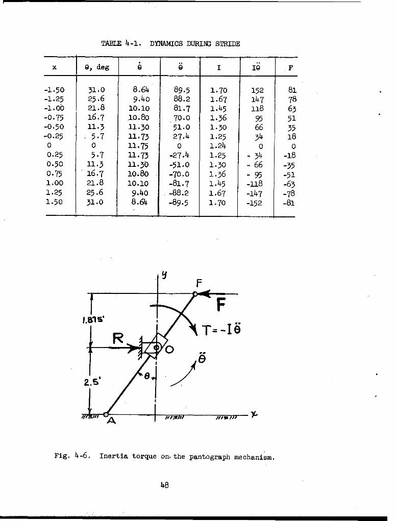
TABLE 4-1. DYNAMICS DURING STRIDE
x 9, deg I@ I1 F
-1.50 31.0 8.64 89.5 1.70 152 81-1.25 25.6 9.4o 88.2 1.67 147 78-1.00 21.8 10.10 81.7 1.45 18 6-0.75 16.7 .10.80 70.0 1.36 95 51-0.50 11.3 11.30 51.0 1.30 66 3-0.25 5.7 11.73 27.4 1.25 34 180 0 11.75 0 1.24 0 00.25 5.7 11-73 -27.4 1.25 - 34 10.50 11.3 1130. -51.0 1.30 - 66 -30.75 16.7 10.80 -70.0 1.36 - 95 -511.00 .21.8 10.10 -81.7 1.45 -118 -61.25 25.6 9.40 -88.2 1.67 -147 -781.50 31-0 8.64 -89.5 1.70 -152 -81
I so
Fig. 4-6. Inertia torque on.the pantograph mechanism.
48

So
tstride 3 0.102 sect v 29.4
Since the four events have equal times, the period is
T = (4) (0.102) = 0.408 sec
For the lift and lower phases of the action we choose to use parabolic
(constant acceieration) motion. The general equations for motion are
x, y = a + bt + ct2 (4-6)
where the constants a, b, and c depend upon the conditions desired at the
beginning and ends of the motion. The coordinates x and y together give
the position of the foot at any instant in time. The first and second
time derivatives of Eq. (476) give the velocity and acceleration, respec-
tively.
The coordinates to be used for this analysis are shown in Fig. 4-7.Point 0, the lowest position of the lift cylinder, is the origin. The x
coordinate, positive to the right, gives the displacement, in the horizontal
Fig. 4-7. Nomenclature.
49
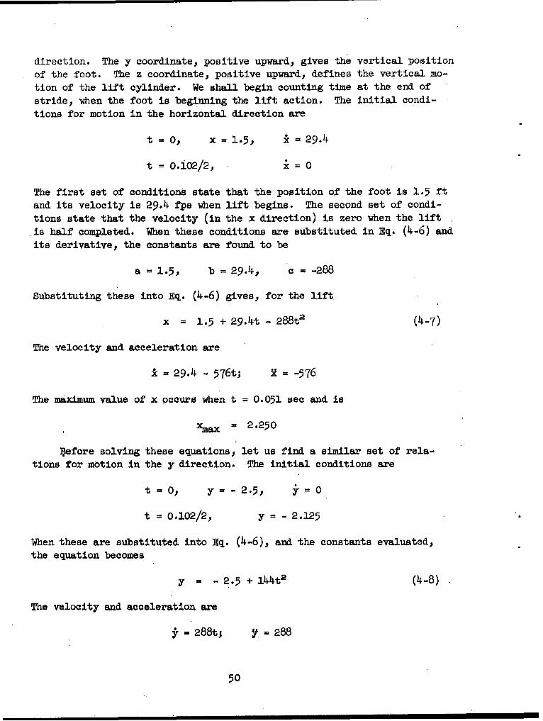
direction. The y coordinate, positive upward, gives the vertical position
of the foot. The z coordinate, positive upward, defines the vertical mo-
tion of the lift cylinder. We shall begin counting time at the end of
stride, when the foot is beginning the lift action. The initial condi-
tions for motion in the horizontal direction are
t = O, x = 1.5, i = 29.4
t = 0.i02/2, i = 0
The first set of conditions state that the position of the foot is 1.5 ft
and its velocity is 29.4 fps when lift begins. The second set of condi-
tions state that the velocity (in the x direction) is zero when the lift
is half completed. When these conditions are substituted in Eq. (4-6) and
its derivative, the constants are found to be
a = 1.5, b = 294, c = -28 8
Substituting these into Eq. (4-6) gives, for the lift
x = 1.5 + 29.4t - 288t' (4-7)
The velocity and acceleration are
k= 29.4 - 576t; R = -576
The maximum value of x occurs when t = 0.051 sec and is
,xa x =2.250
before solving these equations, let us find a similar set of rela-
tions for motion in the y direction. The initial conditions are
t = O, y= -2.5, y=0
t = 0.102/2, y = - 2.125
When these are substituted into Eq. (4-6), and the constants evaluated,the equation becomes
y = -2.5 + 144t2 (4-8)
The velocity and acceleration, are
;ri=288t; y=288
50

Equation (4-8) is only valid for the first half of lift. For the second
half, the boundary conditions are
t = 0.051, y = - 2.125, 14.70
and the equations become
y = - 3.25 + 29.4t - 144t2 (4-9)
=29.4 -288t; y= -288
The relationships between z and y may be found by similar triangles.
The results are
z = 1.071 + 0.4296 (4-10)
i = 0.429r; t = Q.429Y
When all of these equations are solved for various times we get the
results shown in Table 4-2. Note, that at t = 0.051 sec, the accelera-tions in the vertical direction change sign instantly.
With the values of the velocity and acceleration in Table 4-2 the
angle 9 and the angular acceleration 6 of the equivalent linkage may be
calculated. The solution involves the Coriolis component and is best
solved using a graphical approach. Since the analysis is well known,,
only the results will be presented here. It is also convenient to ap.-.
proximate the moment of inertia, graphically, while doing this. All ofthese results are tabulated in Table 4-3. The quantity IQ is the inertia
torque, and F is the piston force, positive in the direction of piston
motion.
The final step, in this procedure, is to prepare another table, sim-
ilar to Table 4-1, for the return action. The analysis is quite similar
and will not be detailed here. The results are included in Table 4-4.
The analysis is now complete and it is only necessary to put the re-
sults together to find out what is going on. Let us first tabulate all
the pertinent information in a single table for easier examination. Table
4-5 gives the inertia forces on the cylinders for a single leg and for one
complete cycle of operation.
If four legs, mounted at one point on the vehicle, are used, and if
the action. is separated in phase by one-quarter period, then the vertical
inertia forces are completely balanced because when one. leg is on lift,
the other leg is on lower, and the two inertia forces are exactly canceled.
51

n~ 0 0 nc 0 O
t- 0 0.- ?(\ H \100 t t ~ -~ n r- H 0
8 00~ \o\ (0 HO0 CU 0CH a K
o6066c0 00 0
wo mOc co 0 C cO co CD O CNU CU C CM CUC CIO NO ICM C?
0O CM cs CO0 0,C c) CO
02 a\ H- CU U- 4
0r o't nt ~-C uooC0 Uco
4 W\ U \ Li Ul\ I(\ L5\ I(\ W\ " U
cm N H
CU U-\ H 04 k 0 08 n
0 00 0 0 H 0 H0O
52

0 t- 0 0 0 I'D 0 ".00 0 0 t.- C)0 O\ CC) Ul\ IC, N4 0 U'\ t~- Go 0N 0
HH
\10 co It, aJ c 0 0 0 0 O co OD VNr' \10'~CD' 0 -t-t t.- 0 tr -
o I(\ ON0 0 O -- co 0 a\ H K\ 0C~j 0\ CO\ R OR CO G\0\0 -C
H0 0 0 j 0 0 0 j 0 0 0H
CD IN-0 0 '- n' 0- N 0 -t R- U' - 0 k
o a \ 0 4 0 0 - 0 0 0 0
0~~ ~ 0 HH0~~~
H- H04',4 H ~ ~
000 \.0 0' O D I CO nx 040 Cti 0' 04j CO 0'H KC,~ '\ 04j H~ Hd H- H- K04 K'-\
o rC, 0 [' 0 I'D Ic' 0 \C', 0 blC\ND K,\ 0 m505 co' 04 0 N C' 40 I' 0 K-\ C'
COj r-I HH4c ~ - CO? C'
r; CO 04 CO K", ~' ' 4 AC' 4- 0; kO
K\i IC', 04 04 KIN H W'l\ nC, I' "
NN 0' W\ _:t COC C . r'N
H8 4 0 0 0 0 H H H
*~~~~S 8- mve S\ H' CI\C H4I'
0 ' ~ g" 4I-
LC\ -0 H 4 040 C 53

rq 0
-H N 4 rl -
fr-\ OJLCt- :4 G\O0 0 0 0 00JtI-,-'Htu'J\ JCUCJH 00 o( K : Nn - NU\J' '., j r4 A A I; A A A AI A I I C C ciC c
o0o oo o 0 a N t0r 0 0 OJN 0
8 PRMdN.PNaLr r r\( m04U\U\W ~
Io 6 I I r 4, Ci i ~ i1 C? Ci I I I I I i a I
0 0 0 0)00))
C) l 3 0)'00))4) 04-a+'+'+a+'
0)0 0404 \ 0 U~ 0) 0 0' '0CJ0OOOn 0oooo-\oo0oooo ra
0o -* D\D L.L f t k OP4 N 0cl K _: W L\ D
C) ODLf\ H K\CD -IC- tt' j coU U-\- I'D 0OD~ n Q\ t--0 0 -U \D0J
IC0\ 04C 0 0 0 0 m H H H H H H H HH\
Nr teN 0 0 8-\ 0
0 rdjrrrd d dro
+) 4-1 4- P 4) 43
n \ 0' LC\ tCN 0L\ 0 Lr\
54
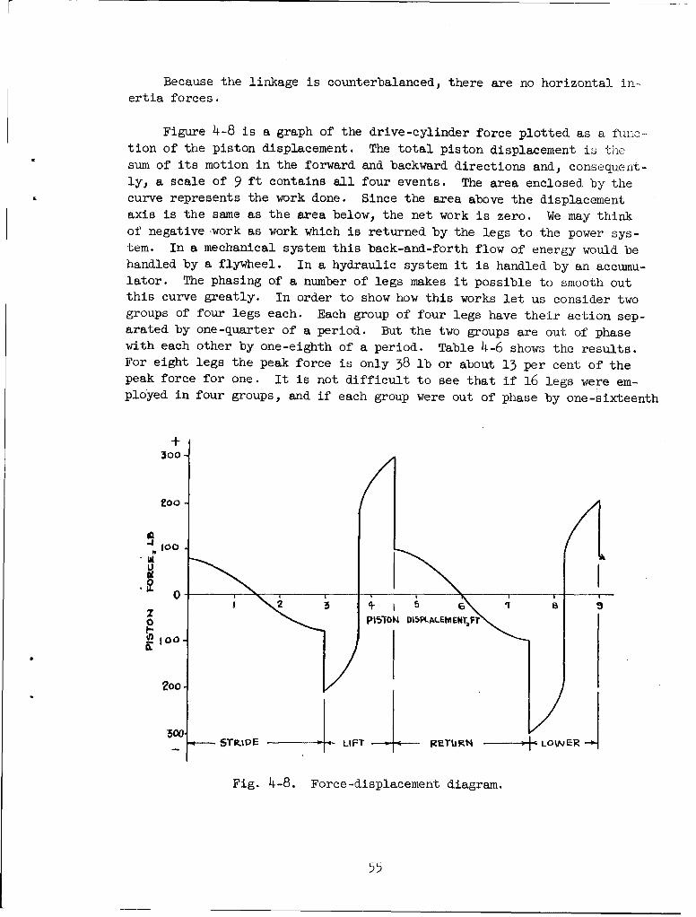
Because the linkage is counterbalanced, there are no horizontal in-ertia forces.
Figure 4-8 is a graph of the drive-cylinder force plotted as a fuim-
tion of the piston displacement. The total piston displacement is thesum of its motion in the forward and backward directions and, consequent-ly, a scale of 9 ft contains all four events. The area enclosed by thecurve represents the work done. Since the area above the displacement
axis is the same as the area below, the net work is zero. We may thinkof negative work as work which is returned by the legs to the power sys-tem. In a mechanical system this back-and-forth flow of energy would behandled by a flywheel. In a hydraulic system it is handled by an accumu-lator. The phasing of a number of legs makes it possible to smooth outthis curve greatly. In order to show how this works let us consider twogroups of four legs each. Each group of four legs have their action sep-arated by one-quarter of a period. But the two groups are out of phasewith each other by one-eighth of a period. Table 4-6 shows the results.For eight legs the peak force is only 38 lb or about 13 per cent of thepeak force for one. It is not difficult to see that if 16 legs were em-ployed in four groups, and if each group were out of phase by one-sixteenth
+
300
Zoo
Z, 1 +500 D1
00
00
S~j ELIFT - - RETURN LWE
Fig. 4-8. Force-displacement diagram.
55

m~a2, 4-6. SUMMATION OF CYLLNDF.R FORCES
The group of four legs have -their actioms one-quarter periodapart. the group of eight legs have their actions one-eighthperiod apart.
t Drive Lift Return Lower 4, Legs 8 Legs
0 81 -207 100 -299 -325 -38
0.0. 72 -174 91' -255 -266 -1
0.02 6o -152 76 -228 -244. - 60003 43 -128 56 -208 -235 60.04 24 -3-15 32 -196 -255 11OoQ51 0 -102 0 -185 -287 580.051 0 185 0 102 287 -380.06 -.24 196 - 32 115 255 -110.07 -43 2o8 - 56 128 235 - 6o.o8 -60 228 - 76 152 244 60.09 -72 255 - 91 174. 266 iiO.102 -81 299 -100 207 325 38
TABLE 4-7. TABULATION OF TOTAL IMMETIA TORQUES FOR
FOUR LEGS AND FOR EIGHT LEGS
t Drive Lift Return Lover 4 Legs 8 Legs
0 152 -388 -156 465 73 -710.01 135 -326 -142 398 65 -510.02 113 -281 -118 362 76 -240.03 81 -232 - 87 337 100 24
o. 4. 4,5 -205 - 50 326 ,116 510.051 0 -174 0 318 144 710.051 0 -318 0 174 -1.44 -71006 - 45 -326 50 205 -116 -510.07 - 81 -337 87 232 -100 -24O.O8 -113 -362 118 281 - 76 240M09 -135 -398 142 326 - 65 51
0.102 -152 -465 i6 388 - 73 71
56

of a period, then the resulting peak would be even less. On the other hand,
if two groups of four legs were in phase with two other groups, then thefigures show. in the column for eight legs would be doubled. Examination
of the time column shows that these figures are not exact, but they are
close enough to show the degree of improvement to be expected.
Our final step in this analysis is to tabulate the inertia torques
for four legs and for eight legs, phased as in the previous example. Ta-
ble 4-7 shows these results. It is clear that the inertia torques are
greatly reduced in magnitude.
4-3. CONTROL SYSTEM FOR PANTOGRAPH LEGS
In devising a control system for the pantograph-legged walking machinewe visualize 16 legs, 4 at each corner, phased to achieve the best balanceof inertia forces and torques. In particular we may desire the following;
1. Ability to control the length of stride of each gang of 4 legs.
2. Ability to control the height of step of each gang.
3. Ability to change the vehicle speed and to reverse its motion.
4. Ability to steer the vehicle by changing the speed of the legson one side relative to the other side.
Figure 4-9 is a schematic drawing of the hydraulic system and the con-trol system. The stride and lift for each gang of 4 legs would be con-trolled by ganged three-dimensional cams, four cams for stride and fourfor lift. The axial dimensions of these cams would bontrol the length of
stride and the height of lift, respectively. The radial shapes would in-itiate and control the four events of the cycle. The phase relationshipof the 4 legs is dictated by the relative angular position in which the
cams are fastened to the cam shaft. The cams representing two gangs of
legs on one side of the vehicle could be on the same cam shaft. Then the
speed of the cam shaft dictates the speed of the legs on that side.
Steering would be accomplished by speeding up the legs on one sideof the vehicle. Since the legs on a single side are quite well balancedthis would have a negligible effect on the inertia forces and torques
transmitted to the vehicle. It would, however, increase the peaks to be
supplied by the accumulator. Taking shorter steps on one side of the ve-hicle could. not be used for steering because this does not change the
speed.
57

LIFT CYLIMVER5 (W RQ. DpIVO CYLINe~tP 04( REQ.)
XL IP? LOW -CON TOL DRIV E FLOW -C NTROL
PROGRAM CONTkOL
5TIELIFT PEIED TEFtNGer puE
L.Ut4-TH HI4T
Fig. 4-9. Block diagram of control system.
58

The problem of how an operator can watch the action of all four feet
simultaneously in order, for example, to step over a ditch., will have tcbe solved using an actual vehicle. It may be that, like a horse, he will
instinctively know where his hind feet are!
4-4. PERFORMANCE OF THE PANTOGRAPH VEHICLE
The pantograph mechanism satisfies all of the requirements outlinedin Sec. 1-2 except No. 6. It is probably impossible to get a high stride-time to return-time ratio and still get balanced inertia forces and torques
no matter how the walking means is accomplished.
59

BIBLIOGRAPHY
1. John A. Hrones and George L. Nelson, Analysis of the Four-Bar Linkage,published jointly by Technology Press, M.I.T., Cambridge, Mass., andJohn Wiley and Sons, Inc., New York, 195l. This is essentially a cata-logue of the coupler curves generated by a very large number of four-bar linkages.
2. Kurt Hain, Angewandte Getriebelehre, Hannover-Dormstadt: Shrodel, 152.
3. F. Freudenstein, "Approximate Synthesis of Four-Bar Linkages," Trans.ASME,77, 85 (1955).
60