Embed Size (px)
Citation preview

NOVEMBER 2007
Assembled by:
TEHAMA COUNTY DEPARTMENT OF PUBLIC WORKS
9380 San Benito Avenue Gerber, CA 96035
Phone: (530) 385-1462 FAX: (530) 385-1182
LAND DEVELOPMENT AND
ENGINEERING DESIGN STANDARDS

CHAPTER 1
Development Policies
CHAPTER 2 Road Policies and Drainage Design
Standards
CHAPTER 3 Mapping and Surveying
CHAPTER 4
Grading and Erosion Control
CHAPTER 5 Sewage Disposal Standards
CHAPTER 6
Fire Safety Standards
CHAPTER 7 Sanitary Sewer and Water System
Standards
CHAPTER 8 Checklists and Sample Documents
CHAPTER 9
Standard Drawings
CHAPTER 10 Drainage Design Tables and Charts
GLOSSARY OF TERMS
NOVEMBER 2007
LAND DEVELOPMENT
AND ENGINEERING
DESIGN STANDARDS
LAND DEVELOPMENT
AND ENGINEERING
DESIGN STANDARDS

TABLE OF CONTENTS PAGE
i
CHAPTER 1 – DEVELOPMENT POLICIES Development Policies ...........................................................................................1-1
General Provisions.............................................................................................1-1 Purpose .............................................................................................................1-1 Environmental, Open Space, Wildland ..............................................................1-1 Exceptions .........................................................................................................1-1 Definitions ..........................................................................................................1-1
Land Development Criteria...................................................................................1-2 Purpose .............................................................................................................1-2 Intent..................................................................................................................1-2 Zoning................................................................................................................1-3 Land Use Classification .....................................................................................1-3 Lands within Close Proximity to City Boundaries...............................................1-3
CHAPTER 2 – ROAD POLICIES AND DRAINAGE DESIGN STANDARDS Road Policies.........................................................................................................2-1
General Requirements.......................................................................................2-1 Exceptions .........................................................................................................2-1 Conformance to the Master Plan .......................................................................2-2 Rights-Of-Way and Access................................................................................2-2 Reimbursement to Developer ............................................................................2-3
Road Standards.....................................................................................................2-3 Road Classes ....................................................................................................2-3 Construction Standards .....................................................................................2-4
Policies and Standards Not A Limitation ............................................................2-4 Construction Standards .......................................................................................2-5
Standard Specifications .....................................................................................2-5 Requirements ....................................................................................................2-6 Control of Work .................................................................................................2-6 Trench Excavation and Backfill for Underground Utilities .................................2-7 Asphalt Concrete ...............................................................................................2-7 Aggregate Base .................................................................................................2-7 Dust Control .......................................................................................................2-7 Embankment Construction.................................................................................2-7 Excavating Below Grade....................................................................................2-7 Aggregate Subbase ...........................................................................................2-8 Concrete ............................................................................................................2-8 Construction Debris ...........................................................................................2-8 Standard Construction Details ...........................................................................2-8 Pipe Lines ..........................................................................................................2-8

TABLE OF CONTENTS PAGE
ii
Miscellaneous Items ..........................................................................................2-8 City Of Red Bluff and City of Corning Standards ...............................................2-8 Acceptance of Work...........................................................................................2-9 Maintenance Bond Required .............................................................................2-9 Construction Bond .............................................................................................2-9 Chip Seal ...........................................................................................................2-9
Drainage ...............................................................................................................2-10 Definitions ........................................................................................................2-10 General Drainage Requirements .....................................................................2-11 Easements.......................................................................................................2-11 Closed Conduits...............................................................................................2-12 Open Channels ................................................................................................2-12 Existing Facilities .............................................................................................2-12 Extent...............................................................................................................2-13 Natural Drainage Courses ...............................................................................2-13 Drainage Diverted Into Swales ........................................................................2-13 Offsite Drainage & Facilities.............................................................................2-13 Drainage Release ............................................................................................2-13 Alignment.........................................................................................................2-14 Drainage Design ..............................................................................................2-14 Valley Gutters ..................................................................................................2-19 Channels..........................................................................................................2-19
Design ..................................................................................................................2-21 General ............................................................................................................2-21 Design Speeds ................................................................................................2-22 Sight Distance..................................................................................................2-24 Grades .............................................................................................................2-24 Minimum Horizontal Curve Radius...................................................................2-26 Corner Site Distance at Rural Intersections .....................................................2-27 Delineation.......................................................................................................2-27 Curb and Gutter ...............................................................................................2-28 Structural Design of Paved Streets ..................................................................2-28 Plan Check and Inspection Fee .......................................................................2-29 Improvement Plans ..........................................................................................2-29 Railroad Crossings...........................................................................................2-30 Utility Systems .................................................................................................2-30 Bridges.............................................................................................................2-30 Embankment Guardrail ...................................................................................2-32 Horizontal Distance to Fixed Object.................................................................2-32

TABLE OF CONTENTS PAGE
iii
CHAPTER 3 – MAPPING AND SURVEYING Mapping and Surveying........................................................................................3-1
Mapping .............................................................................................................3-1 Checking and Filing ...........................................................................................3-2 Subdivision Guarantee ......................................................................................3-3 Repairs of Failures and Defects Agreement ......................................................3-3 Fees...................................................................................................................3-3 Surveying...........................................................................................................3-4 Certificates and Statements...............................................................................3-6
CHAPTER 4 – GRADING AND EROSION CONTROL
This chapter’s release is pending approval of a new County Ordinance and will be published at a later date pending Board of Supervisors approval.
CHAPTER 5 – SEWAGE DISPOSAL STANDARDS Land Divisions Not Served By Community Sewerage .......................................5-1
Disposal Area ....................................................................................................5-1 Disposal Material Characteristics.......................................................................5-2 Percolation Test, Test Pits and Groundwater Monitoring...................................5-2 Subdivisions.......................................................................................................5-5 Maps ..................................................................................................................5-6
Construction and Installation...............................................................................5-6 Onsite Sewage Disposal (General)....................................................................5-6 Area of Disposal Fields and Seepage Pits.........................................................5-7 Septic Tanks ......................................................................................................5-7 Disposal Fields...................................................................................................5-8 Seepage Pits .....................................................................................................5-9 Tehama County Director of Environmental Health Authority............................5-10 Inspections.......................................................................................................5-10
Tehama County Bulletin #1- Guidelines for Monitoring Well Construction and Observation for Mathematical Modeling ...............................................................5-11 Setback Distances for Sewage Disposal Systems ...........................................5-12 CHAPTER 6 – FIRE SAFETY STANDARDS
This chapter’s release is pending approval of a new County Ordinance and will be published at a later date pending Board of Supervisors approval.

TABLE OF CONTENTS PAGE
iv
CHAPTER 7 – SANITARY SEWER AND WATER SYSTEM STANDARDS General Provisions................................................................................................7-1
General Requirements.......................................................................................7-1 Approval and Ownership....................................................................................7-1 Fees and Costs..................................................................................................7-2
Sanitary Sewer Design and Construction Criteria..............................................7-2 General Requirements.......................................................................................7-2 Acceptable Materials..........................................................................................7-4 Flow Criteria.......................................................................................................7-4 Resistance Factor ..............................................................................................7-4 Minimum Slope ..................................................................................................7-4 Minimum Size ....................................................................................................7-4 Minimum Cover..................................................................................................7-5 Manhole Spacing ...............................................................................................7-5 Drop Manholes...................................................................................................7-5 Rodholes............................................................................................................7-5 Final Testing ......................................................................................................7-5 Plugging.............................................................................................................7-5 Maximum Depth of Cover ..................................................................................7-6 Acceptable Depth for Service ............................................................................7-6 Crown Matching and Manhole Inverts................................................................7-6 Vertical/Horizontal Curves .................................................................................7-6 Sewer/Water Main Separation ...........................................................................7-6 Property Line Cleanouts ....................................................................................7-6 Laterals Connecting At Manholes ......................................................................7-6 No Service Connections to Force Mains............................................................7-7 No Joint Service Laterals ...................................................................................7-7 Individual Pumping Systems..............................................................................7-7 Plans..................................................................................................................7-7 Inspection ..........................................................................................................7-7 Compaction Testing ...........................................................................................7-7
Water System Design and Construction Criteria................................................7-8 General Requirements.......................................................................................7-8 Pipe Material ......................................................................................................7-8 Pipe Size............................................................................................................7-8 Fire Hydrants .....................................................................................................7-8 Blowoffs .............................................................................................................7-8 Requirements for Reduced Pressure Backflow Valves, Double Checks, and Detector Checks ...............................................................................................7-9 Air Valves...........................................................................................................7-9 Valves ................................................................................................................7-9

TABLE OF CONTENTS PAGE
v
Minimum Cover..................................................................................................7-9 Plans................................................................................................................7-10 Inspection ........................................................................................................7-10 Compaction Testing .........................................................................................7-10
Technical Specifications for Trench Excavation, Backfill and Surface Restoration .........................................................................................................7-10
General ............................................................................................................7-10 Materials ..........................................................................................................7-11 Workmanship...................................................................................................7-12
Technical Specifications for Sanitary Sewer ....................................................7-14 General ............................................................................................................7-14 Materials ..........................................................................................................7-15 Workmanship...................................................................................................7-16
Technical Specifications for Manholes .............................................................7-21 Materials ..........................................................................................................7-21 Workmanship...................................................................................................7-22
Technical Specifications for Water Main Pipe and Appurtenances................7-24 Materials ..........................................................................................................7-24 Workmanship...................................................................................................7-31
CHAPTER 8 – CHECKLISTS AND SAMPLE DOCUMENTS CHAPTER 9 – STANDARD DRAWINGS CHAPTER 10 – DRAINAGE DESIGN TABLES AND CHARTS GLOSSARY OF TERMS

CHAPTER 1
DEVELOPMENT
POLICIES

CHAPTER 1 – DEVELOPMENT POLICIES A. DEVELOPMENT POLICIES
1. General Provisions
a. Purpose: The purpose of these Land Development Standards is to
provide standards of design, construction methods, kind and use of materials in the implementation of facilities within and adjacent to certain types of development projects permitted by Tehama County and to determine operational procedures in the preparation and review of plans, affected permit applications, tentative maps, final maps and parcel maps.
b. Environmental, Open Space, Wildland: All development projects subject
to these standards will be viewed with the thought of preserving the environment, open space and wildands. Open space is defined for this purpose as “all land and water in the County of Tehama that is not covered by buildings; or any undeveloped or predominately undeveloped land in the County of Tehama that has value for park and recreation purposes, conservation of natural resources, historic preservation and scenic or scientific purposes.
c. Exceptions: All development controlled by County Ordinances referring
to these standards shall comply with standards unless exceptions are granted in accordance with the controlling Ordinance.
d. Definitions: The intent and meaning of the terms that are used in these
standards shall be as defined in Chapter 16.08.010 through 16.08.240 of the Tehama County Code or in Section 1 of the Standard Specifications for Public Works Construction and as noted herein.
1) The Standard Specifications for Public Works Construction
(Greenbook), published by Building News, Inc., 1612 So. Clementine Street, Anaheim, California, 92802, current edition, shall govern the construction materials and procedures of all construction work in Tehama County except as modified by Tehama County Ordinance or by these Standards or future modifications thereof or special conditions on file in the Office of the County Engineer.
2) Development is generally defined as any activity that requires an
approval or permit from a County regulatory agency, i.e. building permit, septic/well permit, encroachment permit, flood plain
1-1

development permit, parcel map, subdivision map, etc. Development subject to these standards consists of:
a) Subdivisions (Tentative and Final Subdivision [Tract] Maps,
Tentative and Final Parcel Maps, and Parcel Map Waivers) – shall comply with these standards as provided in Title 16 of the Tehama County Code;
b) Use Permits – Any improvements, infrastructure, or other work
required as a condition of a Use Permit issued under Chapter 17.70 of the Tehama County Code shall conform to these standards;
c) Onsite Sewage Disposal (Septic) Systems (permitted under
Chapter 9.22 of the Tehama County Code) – shall comply with Chapter 5 of these standards;
d) Building Permits – All improvements required as a condition of
building permit issuance under Section 15.02.340 of the Tehama County Code shall conform to these standards;
e) Encroachment Permits – Any improvements, infrastructure, or
other work required as a condition of an encroachment permit issued under Streets and Highways Code sections 1460 (et seq.) shall conform to these standards.
The Department of Public Works shall periodically review the various forms of development permitted by the County and may recommend amendments to these standards to include other forms of development.
B. LAND DEVELOPMENT CRITERIA
1. Purpose: The purpose of the Land Development Criteria is to establish a
method of determining the standards of improvements required for developments of land subject to these standards and is based on proposed land use and site conditions.
2. Intent: The Regulations, Standards and Procedures provided herein shall be construed to be the minimum necessary to promote and protect the public health, safety and general welfare, and they may be made more restrictive by the approving authority in cases where the approving authority finds such action is deemed necessary to protect the public interest and to ensure sound planning standards or, on the advice of the County Engineer, to ensure sound engineering standards.
1-2
3. Zoning: Where re-zoning is required as a condition of Subdivision approval, such rezoning must be approved by the Board of Supervisors and become effective prior to the recordation of a final subdivision map. Additionally, subdivisions may be initially zoned so that lots are not allowed to be divided, which initial zoning must be approved by the Board of Supervisors and become effective prior to the recordation of a final subdivision map.
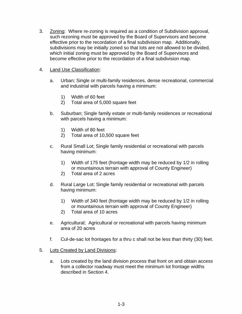
4. Land Use Classification:
a. Urban; Single or multi-family residences, dense recreational, commercial
and industrial with parcels having a minimum:
1) Width of 60 feet 2) Total area of 5,000 square feet
b. Suburban; Single family estate or multi-family residences or recreational
with parcels having a minimum:
1) Width of 80 feet 2) Total area of 10,500 square feet
c. Rural Small Lot; Single family residential or recreational with parcels
having minimum:
1) Width of 175 feet (frontage width may be reduced by 1/2 in rolling or mountainous terrain with approval of County Engineer)
2) Total area of 2 acres
d. Rural Large Lot; Single family residential or recreational with parcels having minimum:
1) Width of 340 feet (frontage width may be reduced by 1/2 in rolling
or mountainous terrain with approval of County Engineer) 2) Total area of 10 acres
e. Agricultural; Agricultural or recreational with parcels having minimum
area of 20 acres
f. Cul-de-sac lot frontages for a thru c shall not be less than thirty (30) feet.
5. Lots Created by Land Divisions:
a. Lots created by the land division process that front on and obtain access from a collector roadway must meet the minimum lot frontage widths described in Section 4.
1-3

1-4
6. Lands within close Proximity to City boundaries:
a. The Planning Director shall notify any Incorporated Cities of proposed subdivisions within 2,500’ of the City/ County boundary line, but failure to give such notification shall not invalidate the subdivision or any proceedings thereon.
C. REVISIONS TO STANDARDS The Director of Public Works may make minor technical revisions to the
drawings, checklists, charts, and standard forms and certificates contained in Chapters 3, 8, 9, and 10 of the Tehama County Land Development and Engineering Design Standards, except that the Public Works Director may not revise the standard form of any improvement agreement contained in the Tehama County Land Development and Engineering Design Standards without approval of the Board of Supervisors. The Department of Public Works shall maintain in the Department’s main office an edition of the Tehama County Land Development and Engineering Design Standards that is current with all revisions.
Inserted December 2008

CHAPTER 2
ROAD POLICIES
AND
DRAINAGE DESIGN
STANDARDS

CHAPTER 2 - ROAD POLICIES AND DRAINAGE DESIGN STANDARDS A. ROAD POLICIES
1. General Requirements
a. No parcel shall be created in the unincorporated area of the County unless it is directly served by a paved road meeting the requirements defined herein.
b. A "paved road" includes the necessary subbase, base, concrete or,
asphalt or chip seal surface and drainage facilities. Road width requirements are defined in Section B of these Standards.
c. These Land Development and Engineering Design Standards provide
the minimum standards for improvements required for development in Tehama County pursuant to the TEHAMA COUNTY CODE.
d. Road improvements are required across the full frontage of properties
that are developed. The minimum road improvement consists of a one half width road improvement with shoulder plus an additional 12-foot lane. The approving authority may also require improvements to the existing public road if it does not meet these Standards.
e. Off site road improvements will be required as necessary to meet the
appropriate traffic impact for the development and road type.
2. Exceptions
a. The approving authority may permit a subdivider or developer to construct a gravel road in designated agriculture areas in conformance with Section B, providing that the following requirements are met:
1) The minimum parcel size is twenty acres.
2) In determining whether to allow the use of a gravel road the
approving authority shall consider all of the following:
a) whether the roadway serves ten (10) parcels or less b) whether the land division is created for family housing c) any other matters relative to whether such action is consistent
with the public welfare.
2-1

3) The approving authority makes findings that the proposed road standard is appropriate for the proposed use and consistent with the definition of that standard in the publication entitled "A Policy on Geometric Design of Highways and Streets," the most current edition by the American Association of State Highway and Transportation Officials and these standards.
The approving authority reserves the right to require an asphalt concrete or chip seal road as described in Section A above.
3. Conformance to the Master Plan
The street design shall conform both in width and alignment to the Circulation Element of the General Plan of Tehama County.
4. Rights-of-Way and Access
a. All roads shall be through roads, except Local, Minor Local and Private
roads. Local, Minor Local and Private roads that are not through roads must end at a cul-de-sac. Emergency ingress and egress shall be provided as required by Chapter 6 Fire Safety Standards.
b. All new and all on-site roads shall have minimum rights-of-way
easement widths as shown on the applicable road sections established under Section B.
c. Rights-of-way or easements for all existing off-site roads used for access
to the development shall be sufficient to permit construction of the required road improvements, but in no case less than 60 feet wide. Where additional off-site rights-of-way or easements must be obtained, the minimum width shall be as shown on the applicable road sections established under Section B. Developer shall exhaust all avenues to obtain necessary off-site rights of way or easements.
d. All on-site and off-site rights-of-way and easements shall be offered for
dedication to the County including any interest the subdivider or developer has in the off-site rights-of-way and easements. The County reserves the right to accept or reject any offer of dedication.
e. When a street or road right-of-way is required to the boundary of the
subdivision to facilitate future traffic circulation, the developer shall dedicate the future street right of way.
f. Where required by these Standards, appropriate width public service
and slope easements adjacent to each side of the road right of way shall be provided and offered for dedication to the County.
2-2

5. Reimbursement To Developer
a. Whenever a requirement that improvements installed by the developer
for the benefit of the development shall contain supplemental size, capacity, number, or length for the benefit of property not within the development, and that those improvements be dedicated to the public, the developer may request from the County an agreement that future development provide a reimbursement for costs for oversizing.
b. In the event of the installation of improvements required by Section 5.a.,
the County may enter into an agreement with the original developer providing that future development be required to reimburse the original developer for that portion of the cost of those improvements in excess of the construction required for the development if all of the following criteria are met:
1) The improvements must reasonably be expected to benefit other
properties in the immediate area.
2) The improvements shall be limited to roads, water mains, sewer mains, traffic signals, intersection improvements, bridges, and major drainage structures which are constructed "off-site."
3) The off-site improvements must constitute an expenditure equal to
at least 25% of the total project cost.
c. The County will recover costs for administration of the offsite improvements and the agreements, which will be added to the reimbursable amount and will be paid by the original developer.
d. These agreements shall only be applied to subsequent subdivisions or
use permits for a maximum period of ten (10) years. B. ROAD STANDARDS
1. Road Classes
a. The following classes of roads are established for all uses except agricultural, commercial and industrial uses:
1) Arterial - Designated in the County's General Plan, arterials
generally provide a connection between the highway network and/or major destinations. Access is limited where feasible (See Chapter 9, Standard Drawings (DWG.) # 0901 and 0903).
2) Collector - Designated in the County's General Plan, collectors
generally accommodate traffic between arterials and/or activity
2-3

centers. Access is limited where feasible, Collector Roads are classified under three categories based on the anticipated ADT; ADT 2000 to 6000, ADT 6000 to 12000, ADT >12,000 (See Chapter 9, DWG. # 0902, 0904, 0905).
3) Local – Local roads are classified under two categories based on
ADT; ADT<400; and ADT 400 to 2000 (See Chapter 9, DWG. # 0905).
4) Private – Private roads are classified under two categories based
on use (See Chapter 9, DWG. # 0906 and 0907).
b. Commercial and industrial roads are classified as an arterial or collector road based on the potential traffic generated by each use as determined by a traffic study approved by the Department of Public Works.
2. Construction Standards
a. Construction of improvements shall conform to the applicable sections
and requirements of Chapter 9, DWG. # 0901 through # 0964 as incorporated herein by reference.
b. Where urban road sections are required, only that portion of the required
roadway which fronts on or lies within the proposed development will be required to be constructed to the full urban width. The remainder of the roadway may be constructed to the rural standard which would be required for the same class of road.
c. In the case where the street improvements have a potential of serving
more lots than is immediately being planned by the subdivider, to the extent that a four-lane road will be required or where the subdivision may have a street shown on the County General Plan as a collector or arterial road, the developer will be required to build only the street improvements indicated by the subdivision street standard for his subdivision, but will provide the right of way for the ultimate four-lane road. If curb and gutter is required, the developer shall install the outer portions of the road for one lane of travel in each direction plus parking.
3. Private Roads
Except as provided in Section B.1.a.4. of Chapter 2 of these Standards, private roads, as defined in Section 9.14.011 of the Tehama County Code, shall meet the minimum requirements set forth in these Standards for public roads in the same classification.
Inserted December 2008
2-4

a. Road Maintenance Agreements - Any Subdivision of five (5) or more parcels that creates, utilizes, or is otherwise directly served by or accessed through, any private road shall be required to establish, execute, and record a Road Maintenance Agreement. The Road Maintenance Agreement shall be binding upon the owners of all parcels created by or otherwise subject to the Subdivision and their successors and assigns (collectively "owners"), and shall require such owners to permanently assume all responsibility for maintaining the road in a good, passable condition under all traffic and weather conditions. The Road Maintenance Agreement shall establish assessments or similar funding mechanisms to provide for such maintenance in perpetuity. The Road Maintenance Agreement shall provide that the County has no responsibility for such maintenance and is indemnified by the owners against any claims related to the road, and that the County has the right, but not the obligation, to enforce the Road Maintenance Agreement as an intended third-party beneficiary. The Road Maintenance Agreement shall be in the form approved by the Director of Public Works and the County Counsel.
b. Public Roads - Any Subdivision of five (5) or more parcels that creates,
utilizes, or is otherwise directly served by or accessed through, any public road that is not part of the County maintained road system shall be subject to the requirements of Section B.3.a. of Chapter 2 of these Standards, provided that an encroachment permit shall be obtained for any maintenance work done pursuant to the Road Maintenance Agreement in the public right of way.
c. Permanent Road Division - Notwithstanding the foregoing, any
Subdivision of five (5) or more parcels that creates, utilizes, or is otherwise directly served by or accessed through any collector street or road, as defined in these Standards, designated by the County Engineer, shall be required to form a Permanent Road Division in accordance with the requirements of the Streets and Highway Code for the maintenance of that collector street or road.
C. POLICIES AND STANDARDS NOT A LIMITATION
1. The policies and standards established by this chapter are not a limitation upon the powers of an approving authority to protect public health and safety and to ensure consistency between projects subject to these policies and standards, the General Plan, all other applicable laws, policies and standards of Tehama County, and all applicable state and federal laws.
2. The approving authority may, with appropriate findings, deviate from the road
policy and construction standards for an individual project if each of the following applies to the subject property:
2-5

a. Because of special circumstances applicable to the property, including size, shape, topography, location or surroundings, the strict application of these road policy and construction standards deprives such property of privileges enjoyed by other property in the vicinity and under identical zoning classification;
b. That the applicant will accept such conditions to the granting of the
deviation requested as will assure that the adjustment thereby authorized shall not constitute a grant of special privileges inconsistent with the limitations upon other properties in the vicinity and zone in which such property is situated;
c. That a hardship peculiar to the property and not created by any act of
the owner exists; in this context, personal, family or financial difficulties, loss of prospective profits and neighboring violations are not hardships justifying a variance; further, a previous variance can never have set a precedent, for each case must be considered only on its individual merits;
d. That the granting of the deviation will not be materially detrimental to the
public health, safety, or welfare or will not impair an adequate supply of light and air to adjacent property; and
e. That the deviation is so insignificant that granting it will not be
incompatible with the county general plan. D. CONSTRUCTION STANDARDS
1. Standard Specifications
The current edition of the "Standard Specifications" of the State of California, Business and Transportation Agency, Department of Transportation, are the Standard Specifications of the County of Tehama. Said Specifications are to be read and interpreted as though the following substitutions of terms were made:
a. County of Tehama for the State;
b. The Board of Supervisors for Director of Transportation;
c. Department of Public Works of the County of Tehama for Department of
Transportation;
d. The Director of Public Works of the County of Tehama acting either directly or through duly authorized agents for the Engineer;
2-6

e. The established laboratory of the Department of Public Works of the County of Tehama or laboratories authorized by the County to test materials and work involved in the contract for laboratory;
2. Requirements
Construction of improvements shall conform to the applicable provisions of the current Standard Specifications, the approved plans and Special Conditions, where directed or approved by the Director of Public Works, and these Tehama County Land Development and Engineering Design Standards.
3. Control of Work
The Developer's Engineer shall set construction stakes, which shall include but not be limited to, initial control stakes, radius points, pipe grades, special ditch and centerline grades, and furnish adequate notes and copies of improvement plans that provide the contractor with sufficient information to construct the improvements and enable the County to check all work in the field. All work performed and materials incorporated therein shall be in strict conformance with the approved plans and specifications, and any change proposed must be approved by the Developer's Engineer and the County before it is incorporated in the work. All work done on the project site is subject to periodic inspection by the County and shall be certified by the Developer’s Engineer.
All work done in the County right of way will be inspected by the County in accordance with the encroachment permit process. Each stage of construction must meet the compaction requirements established for subgrade, subbase, base, and asphalt concrete materials. A 24 hour notice is required for inspection requests.
The Developer shall reimburse the County for all on site and off site inspection costs incurred by County staff.
a. Permits - The developer shall obtain all necessary permits which may
include, but are not limited to: encroachment permits for road, curb, gutter and sidewalk construction from Tehama County and from the California Department of Transportation; streambed alteration permit from the California Department of Fish and Game; and any other permits that may be applicable.
4. Trench Excavation and Backfill for Underground Utilities
All trench backfill between property lines in the street section shall conform to these Standards. In all cases, the class of backfill to be used shall be approved by the County.
2-7

Underground utilities shall include, but not be limited to, water, sewer, telephone, power service, and cable television (if applicable).
5. Chip Seal
This work shall consist of an application of asphaltic emulsion followed with an application of screenings, and another application of asphaltic emulsion followed with another application of screenings.
Screenings shall be medium (3/8" x No. 6) or medium fine (5/16" x No. 8) and conform to the requirements of Section 37-1.02, "Materials," of the Standard Specifications. Asphaltic emulsion shall be LMCRS-2H grade with a liquid rubber latex additive or CRS-2H grade and shall conform to AASHTO requirements and the provisions in Section 94, "Asphaltic Emulsions," of the Standard Specifications.
Before applying asphaltic emulsion to an existing asphalt surface, all loose particles of paving, dirt and all other extraneous material shall be removed. When seal coats are to be applied to aggregate base, the base shall conform to the compaction requirements and be thoroughly dampened immediately before applying the first coat of asphaltic emulsion.
Asphaltic emulsion shall be spread at a uniform rate of between 0.35 and 0.40 gallon per square yard. Immediately following the application of the asphaltic emulsion, it shall be covered with screenings spread with a mechanical device which will spread the screenings at a uniform rate of between 20 and 30 pounds per square yard over the full width of the traffic lane in one application. After the screenings have been spread, any piles, ridges or uneven distribution shall be removed. Rolling shall consist of two complete coverage’s and shall begin immediately behind the spreader.
6. Asphalt Concrete
Asphalt concrete surfacing shall be l/2 inch maximum, Type "B" for less than 0.2 feet thick asphalt and ¾ inch maximum, Type “B” for 0.2 feet thickness and greater, and shall conform to the typical Section and Plans and to the provisions of Section 39 of the Standard Specifications.
A tack coat is to be applied to all existing asphalt surfaces to receive and overlay treatment.
7. Aggregate Base
Aggregate base shall be Class 2 and shall conform to the provisions in Section 26 "Aggregate Bases," of the Standard Specifications and the details shown on the Plans.
2-8

Aggregate for Class 2 aggregate base shall be free from vegetable matter and other deleterious substances, and shall be of such nature that it can be compacted readily under watering and rolling to form a firm, stable base.
8. Dust Control
The subdivider, or his representative, shall be responsible for preventing excessive dust nuisance during the construction operations. Attention is directed to Section 10 of the Standard Specifications.
9. Embankment Construction
All work involved in embankment construction shall conform to the applicable provisions of the Standard Specifications.
10. Excavating Below Grade
Care shall be exercised to prevent excavating below grade, and any areas excavated below grade shall be filled with suitable material and thoroughly compacted as approved by the County. All brush, roots and debris shall be removed from excavated ditches or channels.
11. Aggregate Subbase
Aggregate Subbase shall be Class 3 in conformance with the Standard Specifications.
12. Concrete
The design, proportioning and mixing of all concrete shall be approved by the Director of Public Works and in accordance with the applicable provisions of the Standard Specifications. Curb and sidewalk shall be constructed in accordance with the Standard Specifications.
13. Construction Debris
Brush and timber removed during the construction of roads or building sites shall be removed or otherwise disposed of prior to the following fire season.
Debris shall be disposed of according to the requirements of the County Air Quality Management District and the Fuel Modification Standards – Disposal of Flammable Vegetation and Fuels – of the Tehama County Code, Chapter 9.14.
14. Standard Construction Details
2-9

The Tehama County Development and Engineering Design Standard details included herein shall be used in all cases unless approval is obtained from the Director of Public Works for use of an alternate detail.
15. Pipe Lines
All pipe and other conduit shall be constructed so as to prevent leakage of water due to defective materials, improper joining, corrosion, impact, freezing or other causes.
16. Miscellaneous Items
Miscellaneous items not specifically covered in these Standards shall be constructed in accordance with the appropriate section of the Standard Specifications; or, if not covered by the Standard Specifications, shall be approved by the Director of Public Works.
17. City of Red Bluff and City of Corning Standards
Any subdivision developed within the Sphere of Influence of the City of Red Bluff or the City of Corning shall comply with the respective city standards and specifications unless required otherwise.
18. Acceptance of Work
All work within the County right of way shall be inspected and approved by the County prior to final acceptance. The developer shall contact the County a minimum of 7 days prior to beginning work in order for the County inspector to coordinate an inspection schedule. Failure to contact the County in a timely manner may cause undue delays in the final acceptance of the work at no cost to the County.
Construction within private road subdivisions shall be certified by a registered civil engineer as meeting these Standards. The required compaction on all embankments, subgrade, subbase, aggregate base, and trench backfill shall meet the minimum standards. Such certification shall be provided to the County Department of Public Works prior to final acceptance.
19. Maintenance Bond Required
For newly constructed roads whether private or proposed for acceptance into the County system of maintained mileage, the developer will be required to enter into an agreement with the County guaranteeing workmanship and materials for a minimum of one year. The developer will also be required to post a financial surety acceptable to the County in the amount of 20% of the road improvement cost as approved by the Public Works Department.
20. Construction Bond
2-10
Prior to filing a parcel map or a final map, all improvements required by the conditions of approval shall be completed and approved or the developer will be required to enter into an agreement with the County guaranteeing to construct the improvements within one year. Also, the developer will be required to post a financial surety acceptable to the County in the amount of 100% of the estimated project development cost for labor, materials and performance as approved by the Public Works Department.
E. DRAINAGE
These Standards are to serve as a guideline for storm drainage design and indicate the type of design acceptable to the Department of Public Works.
1. Definitions
a. Lateral: conduits receiving runoff from areas less than 30 acres.
b. Collector: conduits receiving runoff from areas of more than 30 but less
than 100 acres.
c. Trunk: drainage conduits receiving runoff from areas of 100 acres or more.
d. Cross Culvert: Drainage culvert transporting runoff across a roadway.
e. Driveway Culvert: Drainage culvert transporting runoff across driveway.
f. On-Site Drainage Facilities: Shall mean all surface drains and
underground drainage pipe within the development that does not take underground or concentrated surface drainage waters from the adjoining properties.
g. Surface Waters: Water that fall upon, arise from, and naturally spreading
over lands and produced by rainfall, melting snow or springs. They continue to be surface waters until they percolate through the ground or flow vagrantly over the surface of the land into well defined watercourses or streams.
h. Stream Waters: Former surface waters which have gathered together
into a well defined watercourse.
i. Flood Waters: Indicate waters that escape from a watercourse in great volume and flow over adjoining lands in no regular channel. Even though these errant waters may create a temporary channel or follow a natural channel, gully or depression, or give to the course which they follow the character of a natural watercourse, they retain the characteristic of flood waters.
2-11

j. Watercourse: A watercourse as used herein includes:
1) Any natural watercourses or
2) Any man-made watercourse constructed on land owned by a public
agency or on land dedicated to public use for flood control or drainage purposes, or constructed to replace any natural watercourse.
k. Floodplain: Defined as the location where water will naturally go during
a certain recurrence interval.
l. Floodway: Defined as the channel of a river or other watercourse and the adjacent land areas that must be reserved in order to discharge the base (100-year) flood without cumulatively increasing the water surface elevation by more than a designated height (1 foot).
2. General Drainage Requirements
The project shall be designed to receive surface water, stream water, and floodwater emanating from outside its boundaries and from within and passing through and off the development. The project shall be protected from inundation, flood hazard, sheet overflow and ponding of local storm water, springs and other surface water. The design of improvements shall be such that water accumulating within the project will be carried away from the project without adverse effect to any property within the project or any adjacent properties. Water accumulating within the project shall be gathered and conveyed under control to storm drainage facilities or to a natural watercourse by closed conduit or channel. All drainage design within the project shall accommodate the ultimate development within the drainage area. Any off-site drainage facilities to carry storm water from the proposed project to a existing conduit or watercourse shall be adequately sized for the ultimate development in the drainage area. The diversion of natural drainage will be allowed only within the limits of the proposed improvement. All natural drainage must enter and leave the improved area at its original horizontal and vertical alignment.
3. Easements
Drainage facilities must be located in a public street, road or within an easement offered for public dedication. Necessary dedication of easements for drainage facilities to be constructed on private property must be completed before the improvement plans will be approved for construction.
2-12

The County will not accept the maintenance of drainage facilities which are outside of the County maintained right-of-way. Where the improvement of a drainage facility falls on adjacent property, a right of entry must be obtained from the affected property owner for construction of the facility and submitted to the County prior to approval of the improvement plans. Drainage easements shall be used for drainage purposes exclusively and shall not be combined with easements required for other public utility purposes unless it can be shown to the County that dual use of said easement will not be conflicting. All drainage easements shall be shown on the improvement plans and the final map and identified by the words, “Drainage Easement”. Easements shall be provided for all ditches, culverts and closed conduit systems whether constructed as newly built improvements or as rebuilt improvements and shall adequately meet the minimum width specified below.
4. Closed Conduits
Easements for closed conduits shall meet the following requirements:
a. Minimum width of fifteen (15) feet with the centerline of the pipe at third
point; pipe may reverse sides at angle points.
b. Provide access points and working space right of way and easements.
c. For pipes exceeding 24” in diameter or trenches exceeding five (5) feet in depth, the easement shall have additional width to provide ample working space as required by the County.
5. Open Channels
Easements for open channels shall have sufficient width to contain the open channel with side slopes, fencing where required, and a twelve (12) foot wide service road when required by the County. Suitable ramps must be provided for access to the bottom when required. Open channel easements without roads will have a minimum width of ten (10) feet.
6. Existing Facilities
Easements shall be provided for all existing drainage facilities within the boundaries of and/or affected by any land areas to be improved. These existing facilities shall be reconstructed to conform with the County Standards in effect at the time of the overall improvement where such conformance is required.
2-13

7. Extent
All drainage easements shall have public access and extend from the point at which a flow is concentrated to the point of confluence with a natural drainage course.
8. Natural Watercourse
All natural watercourses within the boundaries of an area to be improved shall be provided with drainage easements, extending the full length of the drainage courses within the improved area, and the individual width being consistent with the limit of the 100-year flood way. A natural watercourse is defined as any natural watercourses or any man-made watercourse constructed on land owned by a public agency or on land dedicated to public use for flood control or drainage purposes, or constructed to replace any natural watercourse.
9. Drainage Diverted into Swales
All natural depressions through which drainage travels but not having well defined sides and bottom shall be provided with easements adequate enough in width to provide for both flow and maintenance. At no point shall the width of the drainage easement be less than ten (10) feet. If the waters collected in such swales are not terminated into natural drainage courses within the boundaries of the improvement area, they shall be carried offsite to the point of confluence of the swale with the natural drainage course; adequate drainage easements or drainage release letters from the affected downstream property owner(s) are required.
10. Offsite Drainage & Facilities
All concentrated drainage leaving the boundaries of the area to be improved shall be designed and retained or detained to have no net increase of discharge and shall cause no adverse impacts to downstream property. Specific easements and drainage release letters will be required from the property owners of the lands from the point at which the drainage leaves the limits of the improvement to the point at which it is deposited in a natural water course. At no point shall the drainage easement be less than ten (10) feet in width. The required easements must include adequate provision for all of the drainage structures to be used in the offsite drainage (i.e., culverts, ditches, dissipaters, etc…). Additionally, the developer is required to design and construct any offsite drainage improvement required.
11. Drainage Release
Whenever surface water is discharged from a project's boundary and the location or method of discharge has been changed, the engineer of work
2-14

shall investigate the impact of such on the downstream property owners. Said investigation shall include all properties affected to the point where the surface waters collect into a defined water course. Whenever the engineer determines that the proposed change in surface water runoff has the potential to do damage or where the downstream facilities are not adequate to handle the runoff, the improvement plans shall include all work necessary to mitigate the impact of the change within the project property. If the engineer determines that there is no potential for downstream damage and/or that the downstream facilities are adequate, a statement of such shall appear on the improvement plans. No increase of discharge rate or volume is allowed.
In addition to the above, it will be the developer's responsibility to obtain and record all easements and/or releases necessary to perform or facilitate the work.
12. Alignment
The location of storm drainage pipelines in new streets shall be behind the curb and gutter.
Lines are to be as near parallel with the centerline of the road as possible.
Avoid meandering and unnecessary angular changes.
Angular changes greater than 45 degrees must be located at a manhole type structure with an access for maintenance.
Open ditches, lined channels, swales and floodway areas shall be maintained as nearly as possible in their existing alignment. When an open ditch, other than a roadside ditch, is to be constructed parallel to an existing roadway the ditch shall be constructed outside the proposed right of way of the ultimate roadway development along with an appropriate easement.
The vertical alignment shall be so designed to preclude any ponding within the drainage system.
13. Drainage Design
Drainage calculations and a drainage map shall be submitted with the improvement plans. The following information shall be shown:
a. Offsite drainage in natural water courses
The runoff in any natural water course that collects runoff from an improved area shall no be increased by the designed improvements. All existing drainage facilities offsite and downstream shall be reviewed to
2-15

insure that their capacity is sufficient to safely pass the runoff as calculated at the inlet of the downstream structure. If the existing capacity should prove to be inadequate, the structure and drainage ditch facilities shall be removed and replaced in accordance with County Standards. Any and all additional easement acquisitions necessitated by the rebuilding or relocation of an offsite structure pursuant to this section shall be the responsibility of the developer.
b. Watershed Map
A watershed map shall be required with each set of improvement plans and shall reflect the following criteria:
1) Must be of adequate scale and sufficient accuracy with contour
lines clearly shown and referenced.
2) Individual watershed basins are to be clearly defined by shading with color or patterns and the areas specified in acres.
3) Travel paths must be shown where concentrated flows exist.
Specify if there is sheet flow.
4) Times of concentration for each basin.
5) The quantity of water arriving at each structure, pipe or ditch from a 10-year and a 100-year frequency storm.
c. Drainage Plan
A Drainage Plan shall be required with each set of improvement plans and shall reflect the following criteria:
1) The size of pipe or ditch, proposed length, gradient, type of
material, thickness or class and station location.
2) Invert elevations at both inlet and outlet for each pipe, ditch and structure.
3) Channel dimensions and water surface profile calculations.
4) Downstream conditions that may affect upstream flow.
5) Provide a complete set of engineering calculations for each
drainage basin.
d. Drainage Calculations
2-16

One set of drainage calculations, for each basin, shall be submitted with each set of improvement plans.
1) Design Criteria:
The hydrology analysis criteria shall be used to determine stream flow rates and run off volumes. (Refer to Chapter 10)
This method is applicable to all uncontrolled streams regardless of watershed size or watershed condition. It should not be used where runoff is significantly affected by reservoirs or diversions nor where sufficient (20 years or more) stream flow data exists to permit the use of standard statistical methods.
Once the stream flow rate and runoff volumes have been established, the required drainage facilities shall be designed using accepted engineering practices. Where charts or tables are used, copies shall be submitted.
a) No net increase of runoff from 10, 25 or 100 year events.
b) For developments with one-quarter (1/4) acre zoning a
Rainfall-Runoff method of analysis, such as HEC-HMS, SCS method or equivalent method accepted by the industry, shall be used to calculate the runoff of the watershed.
c) For developments with a watershed less than 40 acres in size,
the rational method that was modified for Tehama County shall be used to calculate the runoff of the watershed. Refer to Chapter 10 for a flow chart of the calculations.
d) For developments with a watershed greater than 40 acres in
size, a Rainfall-Runoff method of analysis, such as HEC-HMS, SCS method or equivalent method accepted by the industry, shall be used to calculate the runoff of the watershed
2) Design Flows:
a) Design all private driveway culverts to accommodate a 10-
year flow without exceeding the allowable headwater depth as determined by Hw/D<1.5.
b) Design all cross culverts to accommodate a 25-year flow with
out causing inundation to the roadway.
c) A 100-year design flow check shall be used to ensure that no flooding occurs on or off site due to the development.
3) Bridges:
2-17

a) All bridges shall be designed to pass a storm with a 100-year
design frequency. Minimum freeboard at bridges will be 2 feet at minor streams and 3 feet at major streams or at sites where stream debris is probable.
4) Detention/Retention Basin:
a) Detention basins shall be required to control runoff so there is
no net increase.
b) Runoff-Rainfall design methods are required in determining the size of a required detention basin.
c) A 100-year design shall be used to design the size of the
detention basin so that no net increase in runoff occurs.
d) Provide discharge calculations for existing predevelopment 10, 25, 100 year flows.
5) Inlets and Outfalls:
a) Inlets shall be examined to determine if inlet flares are needed
to prevent erosion or ensure inlet capacity in the application they are designed. Inlet riser screens shall be used on all detention facilities to prevent debris from entering and becoming clogged inside the structure,
b) All storm drain and pipe outfalls exceeding thirty (30) inches in
diameter shall have steel grates that cover the entire inlet and are removable for service.
c) All outfalls shall have energy dissipaters sized to prevent
erosion and scouring.
e. Culverts and Storm Drains
1) Culverts under driveway entrances for roadside ditches shall be adequate to carry the design flow, but shall be not less than twelve (12) inches inside diameter.
2) Culverts crossing streets shall be of a size adequate to carry the
design flow, but not less than 15 inches inside diameter for concrete and 18 inches for CMP.
3) Culverts under roadway embankment shall extend a minimum of
two (2) feet beyond the toe of the embankment.
2-18

4) Culverts for use outside the roadway may be of any County approved type and strength to meet field conditions. CMP shall have a minimum thickness of 0.064 inches (16 GA.).
5) Culverts in the roadway shall be designed to standard HS20-44 live
load and shall have a design life of 25 years. CMP shall have a minimum wall thickness of 0.064 inches (16 GA.).
Soil resistivity tests by a private soils laboratory shall be performed to determine the appropriate culvert to be used. The engineer's calculations and the laboratory tests shall be submitted with the initial submittal of the improvement plans. If other evidence is available (existing culvert history in the area for example), it may be used in lieu of the resistivity tests at the discretion of the Director of Public Works.
6) The minimum cover, as measured from the top of the culvert to
subgrade, shall be one (1) foot for culverts crossing streets and one-half (0.5) foot for culverts under driveways. The minimum cover, as measured above, for culverts crossing streets may be reduced to one-half (0.5) foot when a Class "C" concrete backfill is used to support the middle third of the culvert diameter.
7) All drainage structures shall be standard Department of Public
Works structures or as approved by the Director of Public Works. Inlet and outlet capacity shall be equal to the design flow.
8) Storm drains shall be provided where the capacity of the curb and
gutter is less than the design storm or where the product of the velocity in feet per second times the depth of flow in feet exceeds six (6).
9) The use of high density polyethylene corrugated pipe may be used
inside and outside of the public right of way under the following conditions:
a) Corrugated high density polyethylene pipe from 12 to 36
inches in diameter shall meet the requirements of AASHTO Designation: M-294 Type S, outer corrugated pipe wall and smooth inner liner, may be used within the roadway prism or under driveway approaches, and where the application is approved by the Director of Public Works.
b) Maximum allowable fill heights over culverts shall be limited to
15 feet for all sizes, unless approved otherwise by the Public Works Department.
2-19
c) Excavation and backfill shall conform to the requirements of Caltrans Standard Specifications, Section 19-3, and as shown for metal pipe on Standard Plan A62F.
d) The couplings shall be corrugated to match the pipe
corrugations and the width shall not be less than 1/2 the nominal diameter of the pipe. Split couplings shall engage an equal number of corrugations on each side of the pipe joint.
e) The minimum depth of cover below finish subgrade shall be
two (2) feet when crossing County maintained roads.
f) The material shall not be used under driveway encroachments unless the ends are protected by a rigid material such as a concrete headwall.
g) Storm drain culvert ends shall be protected with concrete
headwalls at all locations where mechanical cleaning of ditches or culvert entrances will be necessary.
10) The maximum length of pipe between cleanout access points shall
be 200 feet for culverts having a diameter smaller than 24 inches and 300 feet for those having a diameter of 24 inches or larger. Manholes may also be required at additional locations. See Section 838.5 of the Caltrans Highway Design Manual for examples.
14. Valley Gutters
Valley gutters may be provided to carry drainage across intersections whenever underground drainage facilities cannot be reasonably provided. Valley gutters shall not be permitted on arterial, collector, and major local streets.
15. Channels
Developments requiring street sections with curb and gutter shall be constructed with underground drainage facilities or formed and finished reinforced concrete lined ditches.
All open ditches having a top width of ten (10) feet or more shall be designed in an easement wide enough to allow motor vehicles on one side. The access shall have a minimum width of ten (10) feet. This requirement may be waived when, in the opinion of the Director of Public Works, access will not be needed for future maintenance and when, in the opinion of the Mosquito Abatement District Director, access is not needed for mosquito control.
The gradient for earth ditches shall not be less than 0.7%. The gradient for
2-20

lined or paved ditches and gutters shall be not less than 0.25%. Ditches shall be paved or lined when the design velocity exceeds that shown below. Ditches adjacent to the roadway section shall be paved with a dike and down drains as required by the Director of Public Works.
New unlined drainage ditches or relocated natural drains may not be installed closer than 50 feet to the existing or proposed leach lines.
PERMISSIBLE VELOCITIES FOR UNLINED CHANNELS
PERMISSIBLE VELOCITY (FEET PER SECOND)
TYPE OF MATERIAL IN EXCAVATION SECTION INTERMITTENT
FLOW SUSTAINED
FLOW Fine Sand (Noncolloidal)
2.5
2.5
Sandy Loam (Noncolloidal)
2.5
2.5
Silt Loam (Noncolloidal)
3.0
3.0
Fine Loam
3.5
3.5
Volcanic Ash
4.0
3.5
Fine Gravel
4.0
3.5
Stiff Clay (Colloidal)
5.0
4.0
Graded Material (Noncolloidal)
Loam to Gravel
6.5
5.0
Silt to Gravel
7.0
5.5
Gravel
7.5
6.0
Coarse Gravel
8.0
6.5
Gravel to Cobbles (Under 6 Inches)
9.0
7.0
Gravel and Cobbles (Over 8 Inches)
10.0
8.0
STANDARDS FOR CONCRETE CHANNEL LININGS
THICKNESS OF LINING (INCHES) MEAN VELOCITY FEET PER SECOD
SIDES BOTTOM
MINIMUM REINFORCEMENT
Less than 10 2 – 3.5 2 – 4 6”x 6” 10 GA. Wire Mesh
10 to 16 4 – 5 4 – 6 # 3 Bars at 15” Centers Both Ways
16 or more 6 or more 7 or more # 3 Bars at 12” Centers Both Ways
2-21

STANDARDS FOR CHANNEL LISTINGS
THICKNESS OF LINING (INCHES)
MEAN
VELOCITY (FEET PER SECOND)
SIDES
BOTTOM
MINIMUM
REINFORCEMENT *
ASPHALT CONCRETE Less than 5
2
2-3
None
5-10
3
3-4
None
PORTLAND CEMENT CONCRETE **
Less than 10
3-32
32-4 #3 bars @ 18" centers both ways
10-15
4-5
5-6
#3 bars @ 15" centers both ways
15 or More
6 or More
7 or More
#3 bars @ 12" centers both ways
*For small 'V' ditch or trapezoidal concrete lined channels less than 3' deep and 8' wide, minimum reinforcement shall be welded wire fabric 6x6-10x10.
**Air Blown Mortar may be substituted for Portland Cement Concrete where construction complies with Caltrans specifications.
F. DESIGN
1. General
a. The design of all streets shall be in conformance with these development standards. Where specific information is not given, "A Policy on Geometric Design of Highways and Streets, AASHTO" current edition, or the current Caltrans "Highway Design Manual" and "Standard Plans" should be used as approved by the Director of Public Works.
b. Where streets are shown on the General Plan or any adopted Specific
Plans but no plan line has been adopted by the County, the developer will be required to provide the data and establish the alignment of the streets, to the approval of the Director of Public Works.
c. The centerlines of streets entering upon opposite sides of any
intersecting street shall align directly opposite of each other or the centerlines shall be offset at least 200 feet on local and 500 feet on collector streets.
d. All design values shown are minimum. The designer should strive for
higher values whenever possible.
2-22

e. Unless otherwise approved by the Director of Public Works, all improvement plans shall be submitted on standard 24" X 36" mylar plan sheets.
f. Computer generated improvement plans shall conform to the standard
Caltrans drawing format and nomenclature in English units.
g. Definitions
1) LEVEL terrain is the condition where highway sight distances, as governed by both horizontal and vertical restrictions, are generally long or could be made to be so without construction difficulty or major expense.
2) ROLLING terrain is that condition where the natural slopes consistently rise above and fall below the highway grade line and where occasional steep slopes offer some restriction to normal highway horizontal and vertical alignment.
3). MOUNTAINOUS terrain is that condition where longitudinal and transverse changes in the elevation of the ground with respect to a highway are abrupt and where the roadbed is obtained by frequent benching or side hill excavation.
2. Design Speeds
Geometric features of design shall be consistent with the following minimum design Speeds.
a. Minor Local (ADT<400) and Local (ADT 400-2000).
1) Suburban/Rural Designations:
Table 1 (Reference AASHTO)
Minimum Design Speeds (MPH)
TERRAIN
CLASSIFICATION
LEVEL
ROLLING
MOUNTAINOUS Minor Local
30
20
20
Local
40
30
20
Major Local
50
40
30
2) Urban Designations:
The minimum Design Speed for all classifications is 30 MPH. When conditions warrant, and as approved by the Director of Public Works, the Design Speed may be reduced to 20 MPH.
2-23

b. Collector and Arterial Streets
1) Suburban/Rural Designations:
Table 1 (Reference AASHTO)
Minimum Design Speeds (MPH)
TERRAIN
CLASSIFICATION
LEVEL
ROLLING
MOUNTAINOUS Two Lane ADT 2000-6000
60 50 40
Two Lane ADT 6000-12,000
60
50
40
Four Lane ADT >12,000
60
50
40
2) Urban Designations:
The required design speed for all classifications is 30 MPH.
2-24

3. Sight Distance
Minimum stopping sight distance and passing sight distance are a direct function of the design speed. A height of eye of 3.50 feet and a height of object of 2.0 feet is used to determine stopping sight distance. A height of eye of 3.50 feet and a height of object of 4.5 feet is used to determine passing sight distance. All streets shall be designed using the minimum stopping sight distance criteria.
DESIGN SPEED (MPH)
STOPPING SIGHT DISTANCE
(FT)
MIN *K VALUE FOR
CREST VERTICAL CURVES
MIN *K VALUE FOR SAG VERTICAL CURVES
20
125
12
19
25
150
17
24
30
200
30
38
35
250
47
49
40
300
68
62
45
360
98
78
50
430
139
97
55
500
188
116
60
580
253
138
65
660
328
161
70
750
423
188
Minimum stopping sight distance (wet
pavements)
*K value is a coefficient by which the algebraic difference in grade may be multiplied to determine the length in feet of the vertical curve which will provide minimum sight distance.
4. Grades
a. Arterial Streets
1) Suburban/Rural
For rural arterials decrease the maximum grade shown for urban by 2%.
2-25
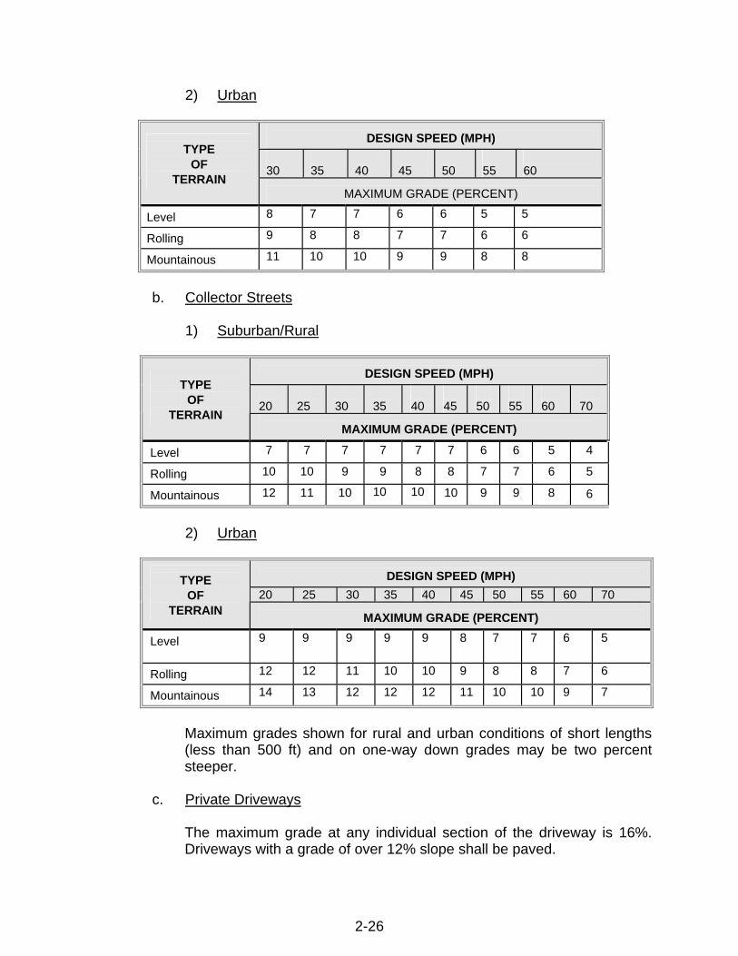
2) Urban
DESIGN SPEED (MPH)
30
35
40
45
50
55
60
TYPE
OF TERRAIN
MAXIMUM GRADE (PERCENT) Level 8 7 7 6 6 5 5 Rolling 9 8 8 7 7 6 6 Mountainous 11 10 10 9 9 8 8
b. Collector Streets
1) Suburban/Rural
DESIGN SPEED (MPH) 20
25
30
35
40
45
50
55
60
70
TYPE
OF TERRAIN
MAXIMUM GRADE (PERCENT) Level 7 7 7 7 7 7 6 6 5 4 Rolling 10 10 9 9 8 8 7 7 6 5 Mountainous 12 11 10 10 10 10 9 9 8 6
2) Urban
DESIGN SPEED (MPH) 20 25 30 35 40 45 50 55 60 70
TYPE
OF TERRAIN
MAXIMUM GRADE (PERCENT) Level 9 9 9 9 9 8 7 7 6 5
Rolling 12 12 11 10 10 9 8 8 7 6 Mountainous 14 13 12 12 12 11 10 10 9 7
Maximum grades shown for rural and urban conditions of short lengths (less than 500 ft) and on one-way down grades may be two percent steeper.
c. Private Driveways
The maximum grade at any individual section of the driveway is 16%. Driveways with a grade of over 12% slope shall be paved.
2-26
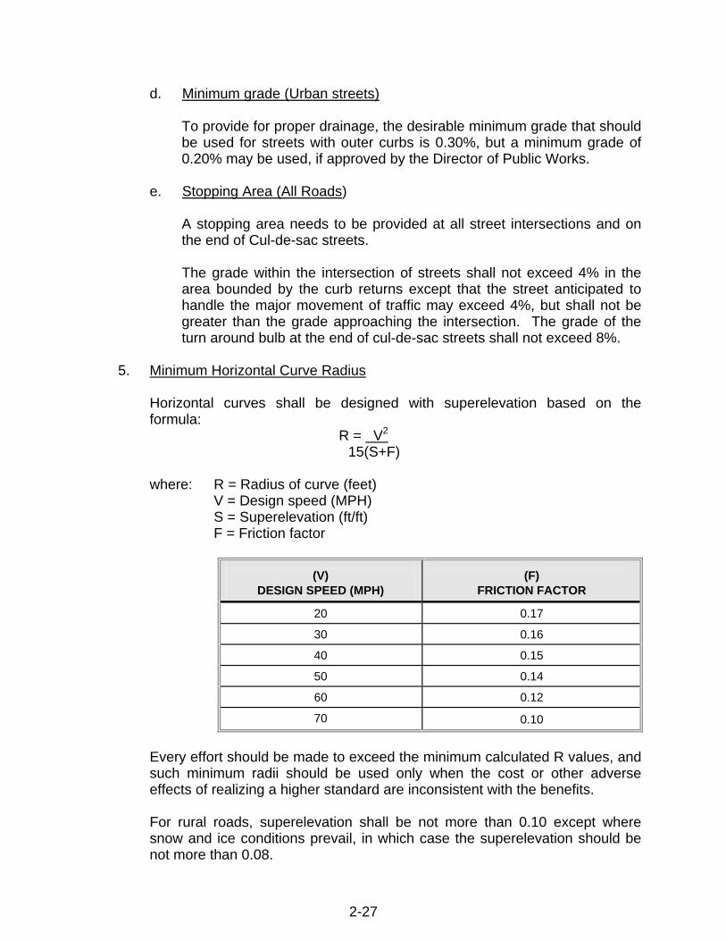
d. Minimum grade (Urban streets)
To provide for proper drainage, the desirable minimum grade that should be used for streets with outer curbs is 0.30%, but a minimum grade of 0.20% may be used, if approved by the Director of Public Works.
e. Stopping Area (All Roads)
A stopping area needs to be provided at all street intersections and on the end of Cul-de-sac streets.
The grade within the intersection of streets shall not exceed 4% in the area bounded by the curb returns except that the street anticipated to handle the major movement of traffic may exceed 4%, but shall not be greater than the grade approaching the intersection. The grade of the turn around bulb at the end of cul-de-sac streets shall not exceed 8%.
5. Minimum Horizontal Curve Radius
Horizontal curves shall be designed with superelevation based on the formula:
R = V2 15(S+F)
where: R = Radius of curve (feet) V = Design speed (MPH) S = Superelevation (ft/ft) F = Friction factor
(V) DESIGN SPEED (MPH)
(F)
FRICTION FACTOR
20
0.17
30
0.16
40
0.15
50
0.14
60
0.12
70
0.10
Every effort should be made to exceed the minimum calculated R values, and such minimum radii should be used only when the cost or other adverse effects of realizing a higher standard are inconsistent with the benefits.
For rural roads, superelevation shall be not more than 0.10 except where snow and ice conditions prevail, in which case the superelevation should be not more than 0.08.
2-27

For urban roads, superelevation shall not be more than 0.03.
Superelevation diagrams with transitions shall be shown on the improvement plans whenever the combination of curve radius and design speed indicates a need for superelevation.
For central angles smaller than 30 minutes, no curve is required.
Curve widening is required for all curves with a radius of 300 feet or less
6. Corner Site Distance at Rural Intersections
Intersections, including median openings, should be designed with adequate corner sight distance as follows:
DESIGN SPEED (MPH)
CORNER INTERSECTION SIGHT
DISTANCE (FT)a
60
660b
50
550
40
440
30
330
20
210
a Corner sight distance measured from a point on the minor road at least 15 feet from the edge of the major road pavement and measured from a height of eye at 3.50 feet on the minor road to a height of object at 2.0 feet on the major road.
b At 60 MPH stopping sight distance governs.
Intersections should be carefully situated to avoid steep profile grades and to ensure adequate approach site distance. An intersection should not be situated on a short-crest vertical curve, just beyond a short-crest vertical curve, or on a sharp horizontal curve. When there is no practical alternate to such a location, the approach sight distance on each leg should be checked carefully.
7. Delineation
At the expense of the developer, street signs, striping, traffic delineation devices, warning and regulatory signs, guard rail, barricades and other similar devices, where required by the Department of Public Works, shall be installed according to accepted engineering practices. Signing shall be in conformance with the Department of Public Works' standards and the current
2-28

MUTCD and the California Supplement. Installation of traffic devices shall be subject to review and modification after construction.
8. Curb and Gutter
When required, standard vertical curb and gutter shall be used in all commercial areas, on all curb returns and at all drainage inlets. In residential areas, either vertical curb and gutter or rolled curb and gutter may be used provided that drainage capacity criteria is met. The minimum transition length from rolled curb to vertical curb shall be five (5) feet.
Curb, gutter, and/or sidewalk will not be required on the portion of the required access road not located within or on the boundaries of the development.
9. Structural Design of Paved Streets
The structural design of paved streets shall be based upon "R" values determined by the current California Test Method 301.
The developer shall have a private soils laboratory perform field tests to determine the "R" value of the material to be used for road construction. Using these values, the developer's engineer will establish the appropriate structural section to be used for each road. Laboratory reports and engineer's calculations used shall be submitted with the initial submittal of the improvements plans.
The following traffic indexes will be used in determining the structural design:
The traffic index shall be: commercial industrial min 7.0
(1)
minor
5.0
(2)
local
6.0
(3)
collector
7.0
(4)
arterial
9.0
The TI’s may be higher as determined by AADTT numbers based on the Public Works Director’s approval.
The minimum thickness of asphalt concrete shall be 0.20 feet and the minimum thickness of Aggregate Base Class II shall be six (6) inches, Chip Sealed, roads shall have a minimum thickness of aggregate base Class II of six (6) inches with a Double Chip Seal surface constructed in accordance with Subsection F.20.
2-29

10. Plan Check and Inspection Fee
The developer shall have improvement plans prepared by a registered civil engineer for all required construction. The plans shall be approved by the Director of Public Works prior to commencement of construction.
The developer shall show existing and proposed location of all utilities, as approved by the utility company and the Director of Public Works, on the improvement plans.
Each set of plans will require an engineer's estimate which itemizes all work including unit cost amounts for each major item of work, such as grading, base, paving, concrete work, drainage facilities, etc. Unit cost amounts should reflect what it would cost the County to do the work if the contract was put out to bid. The unit costs will be verified by the County.
A deposit to cover the improvement plan check and construction inspection is required prior to the improvement plan check. The amount of the deposit shall be as specified in the latest adopted County of Tehama County Public Works and County Surveyor Fee Schedule.
11. Improvement Plans
Maps to be recorded shall be legibly drawn, printed, or reproduced by a process guaranteeing a permanent record in black on tracing cloth, or polyester base film, 24 by 36 inches. If ink is used on polyester base film, the ink surface shall be coated with a suitable substance to assure permanent legibility. A one-inch blank margin shall be left on each edge of the map. No certificate stick-ons will be accepted and no stick-on shaded film to denote greenbelt areas or other purposes will be accepted.
A complete set of Improvement Plans, for both Parcel maps and Tract maps, are required and shall meet the following minimum criteria:
a. Cover sheet with project location, vicinity map, legend, project quantities,
approval signature blocks, sheet index, general notes and all owner and engineer information.
b. Project layout sheet showing the entire project and sheet references.
c. General plan sheet showing existing topographic details and project
features.
d. Grading plan including total cut, fill, and import/export quantities.
e. Watershed Map
2-30

f. Erosion control plan showing BMP’s, locations, erosion control notes and erosion control methods.
g. Drainage Plan
h. Roadway plan and profile sheets with a horizontal scale of one (1) inch
to fifty (50) feet and a vertical scale of one (1) inch to five (5) feet or ten (10) feet depending upon the terrain and special details with a horizontal scale of one (1) inch to twenty (20) feet. An alternate scale may be used on smaller projects to include more detail.
i. Detail plan sheet outlining all pertinent details that are common to the
project.
j. Traffic control plan (if applicable) including all temporary and permanent traffic control stripping, devices and delineation.
k. All sheets shall have a defined scale, title block, and revision block in
accordance with these Standards (See Chapter 9, DWG. # 0964).
l. Permanent elevation bench marks referring to an approved datum may be required to be set at a location approved by the County Surveyor.
12. Railroad Crossings
Provisions shall be made for any and all railroad crossings necessary to provide street access to or circulation within the proposed development, including the preparation of all documents necessary for approval from the California State Public Utilities Commission and appropriate railroad for establishment and improvement of such crossing. The cost of such railroad crossing improvement, including all necessary approval documents, shall be borne by the developer.
13. Utility Systems
In the case of developments included within an existing and operating Water, Public Utility, or Community Services District, the developer shall install the utility system and appurtenances in conformance with the standards established by the district. The developer shall furnish a letter from the district certifying that the improvement design is to their standards prior to approval of construction plans by the Director of Public Works. Prior to the placement of permanent surfacing over utility trenches, the developer shall furnish evidence from the district certifying that the improvements have been installed to their satisfaction. Within sixty (60) days of project completion as-built drawings of all constructed facilities shall be submitted to the County.
2-31

14. Bridges
All highway bridges shall be designed in accordance with the current edition and interims of the AASHTO Standard Specifications for Highway Bridges, including Caltrans revisions, unless specified otherwise in these standards.
When the Service Load Method of design is allowed, the design live load shall be HS20-44 and alternate loading.
All structures designed with the Load Factor Design (LFD) criteria shall apply the permit design live loads ("P" loads).
All bridge plans shall show General Notes containing a statement as to the criteria for design, either AASHTO Service Load or AASHTO Load Factor. In addition, as a minimum, the design live loads, allowable and design footing pressure, pile design load, and allowable design stresses for reinforced concrete, prestressed concrete or structural steel, shall be shown.
The width of all new highway bridges, shall equal the full width of the traveled way and additional width as required by AASHTO. The width shall be measured normal to the centerline between vertical faces of curb, parapet or rail.
Vertical and horizontal clearances for traffic ways under bridges shall comply with the current AASHTO standards.
Allowable bridge materials are:
1) Structural Steel 2) Reinforced Concrete 3) Treated Timber (driveways only)
a. Bridge Railings
All bridges, culverts, retaining walls or other structures will be reviewed for installation of protective railings.
The railing will conform to current applicable AASHTO, OSHA, or Caltrans standards for geometric layout and design standards.
b. Foundation Investigation for Design
A foundation investigation by an engineering geologist or civil engineer will generally be required at all bridge sites. This requirement may be waived by the Director of Public Works if site conditions show the report to be unnecessary.
2-32

All reports shall contain recommendations by the civil engineer or engineering geologist for specific design considerations for the site. Soil support values, pile tip elevations, and point of fixity or piles with extensions should be included.
When required by the Director of Public Works, the foundation report shall also contain the following information:
1) Maximum credible rock acceleration 2) The magnitude of the maximum credible event 3) Depth to "rock-like" material
c. Private Bridges (Driveways Only)
All bridges require submission of plans and calculations (prepared by a civil engineer with a current valid registration in the State of California) to the County Building Department for issuance of a building permit in consultation with the Public Works Department.
For all permanent structures, foundations shall be constructed of masonry or concrete and, in all cases, extend below the frost lines as provided for in Section 2907 of C.B.C. Other types of foundation materials may be permitted upon submission of acceptable test data, calculations, or other information relating to the properties and load-carrying capacity of such material. Section 2517 (c), C.B.C., provides for treated timber for the support of permanent structures embedded or in direct contact with the earth. The remainder of the bridge may be constructed of any material suitable for the structural capacity. All permanent structures shall comply with Chapter 6, Section B for width and vertical clearance requirements.
The minimum design live load should be as required by Chapter 6, but in no case less than the minimum loading of AASHTO H-15-44.
For all pedestrian bridges, the design live load should be as recommended by AASHTO at 85 pounds per square foot of walkway area.
15. Embankment Guardrail
Embankment guardrail shall be designed in accordance with the height and slope of the embankment or sidehill as shown in the latest version of the Roadside Design Guide published by the American Association of State Highway and Transportation Officials. Where guardrail is required, the embankment shall be widened to accommodate the guardrail flare as shown in Caltrans Standard Plans.
2-33

2-34
16. Horizontal Distance To Fixed Object
On new alignments, without sidewalks, the minimum horizontal clearance from the edge of pavement to the fixed object shall be as determined from the latest version of the Roadside Design Guide. All effort should be made to exceed this minimum. Objects at or near the ends of horizontal curves may have to be relocated to increase this minimum distance.

CHAPTER 3
MAPPING
AND
SURVEYING

CHAPTER 3 - MAPPING AND SURVEYING A. MAPPING AND SURVEYING
All final maps, parcel maps, and record of surveys shall conform to the requirements set forth in this chapter, unless provided for in the current Subdivision Map Act and Land Surveyors Act. See Chapter 8 for submittal requirements and standard documents.
1. Mapping
The scale of the map shall not be less than one inch equals one hundred feet (l" = 100'), except that an alternate scale may be approved by the County Surveyor.
The minimum height of all lettering shall be l/8-inch hand or l/10-inch machine lettered.
When the map consists of more than three (3) sheets, exclusive of the certificate sheet, a key map showing the relation of the sheets shall be placed on the first map sheet. The sheets shall be numbered beginning with the certificate sheets then continuing with the map sheets, and an informational sheet as required.
Dimensions of lots shall be given as total dimensions, corner to corner, and shall be shown in feet and hundredths of a foot. No ditto marks shall be used. Lots containing one (1) acre or more shall show acreage to nearest hundredth. Lots of less than one (1) acre shall show square footage. Gross and net (gross less; right of ways and easements) areas will be shown on all parcels smaller than two (2) acres.
Final Map and Parcel Maps shall contain a title consisting of the assigned tract or parcel map number and name, and a sub-title or general description of all the property being subdivided. Reference to previous maps of record shall be given.
The map shall show clearly what stakes, monuments or other evidence were found on the ground to determine the boundaries of the subdivision. All adjoining subdivisions shall be identified by lot and block numbers, subdivision name and place of record, or other proper designation.
The bearing and length of every lot line, block line and boundary line shall be shown. Bearing and lengths of tangents, and radii, arc length, and delta for all curves as may be necessary to determine the location of the center of curves and tangent points shall be shown. All radial lines shall be identified.
All lots and or parcels shall be identified as such and/or numbered or lettered on the Final or Parcel Map. If the lots or parcels are numbered, they shall begin with the number "1" and shall continue consecutively in numeric order throughout the subdivision with no omissions or duplications. If the lots or parcels are lettered, they shall begin with the letter "A" and shall continue consecutively in
3-1

alphabetical order throughout the subdivision with no omissions or duplications. Whenever the Director of Public Works and/or County Engineer have established the center line of a street or alley adjacent to or in the proposed subdivision, the record data shall be shown on the map indicating all monuments found, not found or reset. If the points were reset by ties, the course and detail of relocation data used shall be stated.
Final Maps or Parcel Maps shall show all easements to which the lots are subject. The easements must be clearly labeled by solid capital letters and identified, and if already of record, the record reference given. If any easement is not definitely located by record, a statement of such must appear on the map sheet. Easements shall be denoted by fine dashed lines. The width of the easement and the lengths and bearings of the lines thereof and sufficient ties thereto to definitely locate the easement with respect to the subdivision must be shown. If the easement is being dedicated by the map, it shall be properly referenced in the owner's certificate of dedication.
Boundary lines of all political subdivisions crossing or bounding the subdivision shall be clearly designated and referenced.
Map accuracy shall be such that any and all calculated closures shall be 1 in 10,000 or greater. All mapped properties, parcels, or other entities shall close within 0.03 feet or 03 seconds of angle.
2. Checking and Filing
A complete set of calculations shall be submitted with the initial check set for all maps submitted for review. The calculations shall be done by computer. They shall include at least the following: all corresponding points shall be labeled on both the check prints and the calculations, courses and closures for all lots, roads, easements, aliquot parts of sections shown, and for the exterior boundary of the entire subdivision, and acreages for all lots.
Maps to be recorded shall be legibly drawn, printed, or reproduced by a process guaranteeing a permanent record in black on tracing cloth, or polyester base film, 18 by 26 inches. If ink is used on polyester base film, the ink surface shall be coated with a suitable substance to assure permanent legibility. A one-inch blank margin shall be left on each edge of the map.
Only copies with the original signatures will be accepted. Signatures on acknowledgements must be exactly the same as on Owner's Certificate and must be written in black permanent ink.
No certificate stick-ons will be accepted and no stick-on shaded film to denote greenbelt areas or other purposes will be accepted. The County Surveyor shall review the Final Map or Parcel Map and when the original mylar and all imposed conditions is deemed to be complete and in order,
3-2

the County Surveyor shall sign and date the County Surveyors Statement appearing on said map. The County Surveyor shall notify the subdivider and / or his engineer of said action. Should a Final Map or Parcel Map require Board of Supervisor approval, the County Surveyor shall, within twenty (20) days of the date of signing said map, prepare and submit an agenda request form to the Clerk of the Board of Supervisors Office for appropriate Board of Supervisors’ action. Following Board of Supervisors approval and signing by the Clerk of the Board of Supervisors the original mylars, and appurtenant documents shall be forwarded to the County Recorders Office, for review and processing prior to recording. Government Code allows up to ten (10) days for processing. For Parcel Maps that do not require Board of Supervisors approval the County Surveyor shall forward the signed original mylars to the County Recorders Office for review and processing, allowing up to ten (10) days prior to final recordation of mylars.
3. Subdivision Guarantee (as applicable)
Submittal of a subdivision improvement guarantee shall comply with Chapter 5, Article 6, Section 66465 of the California Subdivision Map Act.
This is required when the Final Map or Parcel Map is submitted for recording prior to the completion of required physical improvements. Owners' signatures shall be the same on the map as on the subdivision guarantee letter.
The subdivision guarantee letter must have been issued within 10 days of the recording date of the map.
4. Repairs of Failures and Defects Agreement (as applicable)
This is required when the final map or parcel map is submitted for recording and physical improvements have been constructed in accordance with the conditions of approval (See Chapter 8). The agreement must be signed by the property owner(s) and must include the proper surety in compliance with Chapter 5, Section 66499 of the California Subdivision Map Act. The required surety amount shall be equal to 20% of the total estimated cost shown on the Engineer’s Cost Estimate per Attachment B, Chapter 8-28.
3-3

5. Fees
At the time the Final Map, Parcel Map, Parcel Map Waiver documents, Record of Survey, Amending Map, Certificate of Correction or Corner Record is submitted for checking; the map checking fees shall be deposited with the Department of Public Works in an amount established by the Board of Supervisors by resolution. Recording fees are to be paid prior to recording.
6. Surveying All surveys shall be performed in compliance with the provisions of the Land Surveyors Act, Business and Professions Code, Section 8759 to 8774.5, of the State of California. All surveys shall be performed in accordance with accepted good practices of the industry. a. Basis of Bearings
Each map shall contain a Basis of Bearings Note which includes the description and bearing of the line used as the basis, the record data of the map or document from which it was obtained, or a statement that said bearing is based on either a solar or polaris observation.
The following are acceptable basis of bearings:
1) Record Maps held by the County Surveyor or Recorder.
2) Astronomical Observation. The note will describe the object
observed, the date, and the location of the project form which observations were made.
3) California Coordinate System. A statement will be provided in
accordance with the requirements of the Land Surveyors Act, Business and Professions Code (Sections 8771.5) and Sections 8801 to 8819 of the Public Resources Code.
4) GPS observation.
5) Government Records and other records as approved by the County
Surveyor.
b. Accuracy
All field survey accuracy shall be in compliance with acceptable surveying practices. Terrestrial surveys shall have a minimum accuracy of 1 in 10,000, with angular and linear accuracy proportional. Global Positioning System (GPS) system surveys shall conform to the standards set forth in Sections 8801 to 8819 of the Public Resources Code.
3-4

c. Datum
All maps shall provide a note that describes the datum used as the basis for survey if other than a plane survey of limited extent conducted at the surface of the earth. Survey datum requiring additional information are, but are not limited to, State Plane Coordinates, or the geoid or ellipsoid.
d. Monuments
Monumentation shall be in compliance with the Business and Professions Code (Section 8772), and other codes and ordinances where applicable. All monuments shall be of a permanent type and constructed of, or contain, ferrous or other magnetic material that will responded to metal detectors employed by surveying professionals. Any monument or point set by a licensed land surveyor or registered civil engineer, to mark or reference a point on a property or land line, shall be permanently and visibly marked or tagged with the certificate number of the surveyor or civil engineer setting it. (Business and Professions Code 8772). Any untagged pipe or monument, of any type, used by the surveyor or engineer as part of his survey, shall be tagged or marked with his registration number. All lot corners in subdivisions and parcel maps shall be monumented, with the exception of parcel maps creating four or fewer parcels which may be compiled from record data provided the criteria set forth in the Subdivision Map Act, Chapter 2 - Maps, Article 3, Parcel Maps, Section 66448, is met. In addition, monuments shall be set at all angle and curve points on the exterior boundaries and on the right of way line. Tehama County standard centerline monuments shall be set at all street intersections and terminations. Additional monumentation may be required if determined necessary, by the County Surveyor, to perpetuate or facilitate re-establishment of any point or line of the survey.
Any monument or bench mark, as required by these specifications that is disturbed or destroyed before acceptance of all improvements, shall be replaced by the subdivider.
All monuments shall be of a permanent type. The following are approved as permanent: For section and quarter corners, the following monuments shall be set: 1) A brass disk, at least 2-1/2 inches in diameter, set in pavement, and
marked or stamped. 2) An iron pipe, at least two (2) inches in outside diameter, and at least
eighteen (18) inches long, filled with concrete or other permanent
3-5
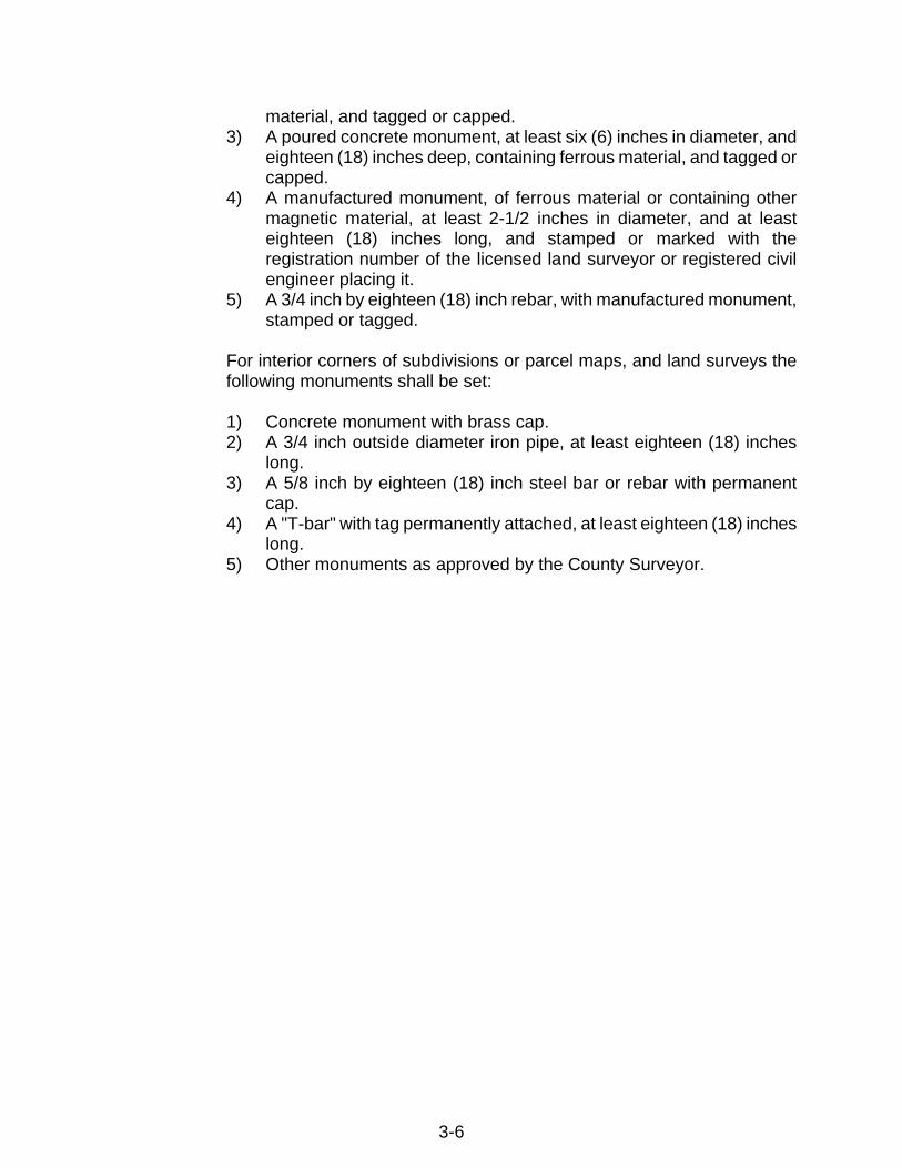
3-6
material, and tagged or capped. 3) A poured concrete monument, at least six (6) inches in diameter, and
eighteen (18) inches deep, containing ferrous material, and tagged or capped.
4) A manufactured monument, of ferrous material or containing other magnetic material, at least 2-1/2 inches in diameter, and at least eighteen (18) inches long, and stamped or marked with the registration number of the licensed land surveyor or registered civil engineer placing it.
5) A 3/4 inch by eighteen (18) inch rebar, with manufactured monument, stamped or tagged.
For interior corners of subdivisions or parcel maps, and land surveys the following monuments shall be set:
1) Concrete monument with brass cap. 2) A 3/4 inch outside diameter iron pipe, at least eighteen (18) inches
long. 3) A 5/8 inch by eighteen (18) inch steel bar or rebar with permanent
cap. 4) A "T-bar" with tag permanently attached, at least eighteen (18) inches
long. 5) Other monuments as approved by the County Surveyor.

7. Certificates and Statements
a. The following certificates are required on Final Maps.
OWNER(S)'S STATEMENT (I) (WE) HEREBY CERTIFY THAT (I) (WE) (AM) (ARE) THE OWNER(S) OF, OR HAVE SOME RIGHT, TITLE, OR INTEREST IN AND TO THE REAL PROPERTY INCLUDED WITHIN THE BOUNDARY SHOWN UPON THIS MAP, AND THAT (I) (WE) (AM) (ARE) THE ONLY PERSON(S) WHOSE CONSENT IS NECESSARY TO PASS A CLEAR TITLE TO SAID PROPERTY, AND (I) (WE) CONSENT TO THE PREPARATION AND RECORDATION OF SAID MAP AS SHOWN WITHIN THE COLORED BORDER LINES AND HEREBY MAKES AN IRREVOCABLE OFFER TO DEDICATE TO THE COUNTY OF TEHAMA AND TO THE PUBLIC, THE PUBLIC ROAD EASEMENTS AS SHOWN ON SAID MAP. OWNER ACKNOWLEDGES THAT NOTWITHSTANDING ANY REJECTION OF THE OFFER OF DEDICATION, SUCH OFFER SHALL REMAIN OPEN PURSUANT TO GOVERNMENT CODE SECTION 66477.2. [NAME OF ROAD] ON THIS MAP IS A PUBLIC ROAD, BUT HAS NOT BEEN ACCEPTED INTO THE TEHAMA COUNTY MAINTAINED ROAD SYSTEM AND THE COUNTY OF TEHAMA WILL NOT MAINTAIN SUCH ROAD UNLESS AT SOME FUTURE TIME IT IS ACCEPTED BY THE BOARD OF SUPERVISORS INTO THE COUNTY MAINTAINED ROAD SYSTEM, AS APPLICABLE By By By By THE CERTIFICATES OF ACKNOWLEDGEMENTS MUST BE SUBSTANTIALLY IN THE FORM OF THE FOLLOWING: STATE OF ) ) SS. COUNTY OF ) ON ___________________ BEFORE ME, , DATE NAME, TITLE OF OFFICER, E.G. "JANE DOE, NOTARY PUBLIC" PERSONALLY APPEARED , PERSONALLY KNOWN TO ME OR PROVED TO ME ON THE BASIS OF SATISFACTORY EVIDENCE TO BE THE PERSON(S) WHOSE NAME(S) IS/ARE SUBSCRIBED TO THE WITHIN INSTRUMENT AND ACKNOWLEDGED TO ME THAT HE/SHE/THEY EXECUTED THE SAME IN HIS/HER/THEIR AUTHORIZED CAPACITY(IES), AND THAT BY HIS/HER/THEIR SIGNATURE(S) ON THE INSTRUMENT THE PERSON(S), OR THE ENTITY UPON BEHALF OF WHICH THE PERSON(S) ACTED, EXECUTED THE INSTRUMENT. WITNESS MY HAND AND OFFICIAL SEAL. SEAL SIGNATURE OF NOTARY COUNTY
3-7

STATEMENT OF CLERK OF BOARD OF SUPERVISORS I, , CLERK OF THE BOARD OF SUPERVISORS OF COUNTY OF TEHAMA, HEREBY CERTIFY THAT SAID BOARD APPROVED THE WITHIN MAP ON THE DAY OF , 20 , AND ACCEPTED ON BEHALF OF THE PUBLIC, THE OFFER TO DEDICATE [NAME OF ROAD] IS ACCEPTED SOLELY FOR THE PURPOSE OF DESIGNATING THE ROAD FOR PUBLIC USE. THE COUNTY OF TEHAMA BY THIS ACTION IS NOT ACCEPTING THE ROAD INTO THE COUNTY MAINTAINED ROAD SYSTEM AND THE COUNTY WILL NOT BE RESPONSIBLE FOR MAINTENANCE OF THE ROAD. BY CLERK OF THE BOARD OF SUPERVISORS OF THE COUNTY OF TEHAMA, STATE OF CALIFORNIA BY Deputy COUNTY SURVEYOR CERTIFICATE I, , COUNTY SURVEYOR OF TEHAMA COUNTY, HEREBY CERTIFY THAT I HAVE EXAMINED THIS MAP; THAT THE SUBDIVISION AS SHOWN HEREON IS SUBSTANTIALLY THE SAME AS IT APPEARED ON THE TENTATIVE MAP AND ANY APPROVED ALTERATION THEREOF AS APPROVED BY THE TEHAMA COUNTY PLANNING COMMISSION ON , 20 ; THAT ALL THE PROVISIONS OF THE CALIFORNIA "SUBDIVISION MAP ACT," AS AMENDED, AND OF THE TEHAMA COUNTY ORDINANCE CODE, APPLICABLE AT THE TIME OF APPROVAL OF SAID TENTATIVE MAP, HAVE BEEN COMPLIED WITH AND THIS MAP IS TECHNICALLY CORRECT. COUNTY SURVEYOR, TEHAMA COUNTY, CALIFORNIA DATE
3-8

3-9
(ENGINEER'S) (SURVEYOR'S) CERTIFICATE I, , (LICENSED LAND SURVEYOR) (REGISTERED CIVIL ENGINEER), HEREBY CERTIFY THAT THIS MAP CORRECTLY REPRESENTS A SURVEY MADE UNDER MY DIRECTION DURING , 20 , THAT THE SURVEY IS TRUE AND COMPLETE AS SHOWN (THAT THE MONUMENTS ARE OF THE CHARACTER AND OCCUPY THE POSITIONS INDICATED), (THAT THE MONUMENTS ARE OF THE CHARACTER AND THEY WILL BE SET IN SUCH POSITIONS ON OR BEFORE , 20 ,) AND THAT THE MONUMENTS (ARE) (WILL BE) SUFFICIENT TO ENABLE THE SURVEY TO BE RETRACED. (LICENSED LAND SURVEYOR L.S.) (CIVIL ENGINEER R.C.E.) RECORDER'S STATEMENT FILED THIS DAY OF 20 , AT M., IN BOOK OF MAPS AT PAGE AT THE REQUEST OF SIGNED TEHAMA COUNTY RECORDER BY DEPUTY
Revised July 2008
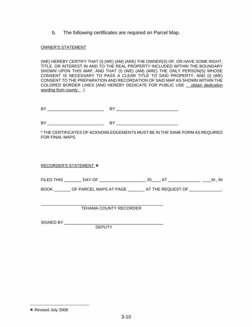
b. The following certificates are required on Parcel Map. OWNER'S STATEMENT (WE) HEREBY CERTIFY THAT (I) (WE) (AM) (ARE) THE OWNER(S) OF, OR HAVE SOME RIGHT, TITLE, OR INTEREST IN AND TO THE REAL PROPERTY INCLUDED WITHIN THE BOUNDARY SHOWN UPON THIS MAP, AND THAT (I) (WE) (AM) (ARE) THE ONLY PERSON(S) WHOSE CONSENT IS NECESSARY TO PASS A CLEAR TITLE TO SAID PROPERTY, AND (I) (WE) CONSENT TO THE PREPARATION AND RECORDATION OF SAID MAP AS SHOWN WITHIN THE COLORED BORDER LINES (AND HEREBY DEDICATE FOR PUBLIC USE obtain dedication wording from county .) BY BY BY BY * THE CERTIFICATES OF ACKNOWLEDGEMENTS MUST BE IN THE SAME FORM AS REQUIRED FOR FINAL MAPS. RECORDER'S STATEMENT FILED THIS DAY OF , 20 , AT M., IN BOOK OF PARCEL MAPS AT PAGE AT THE REQUEST OF . TEHAMA COUNTY RECORDER SIGNED BY DEPUTY
Revised July 2008
3-10

3-11
(ENGINEER'S) (SURVEYOR'S) CERTIFICATE THIS MAP WAS PREPARED BY ME OR UNDER MY DIRECTION (AND WAS COMPILED FROM RECORD DATA) (AND IS BASED UPON A FIELD SURVEY) IN CONFORMANCE WITH THE REQUIREMENTS OF THE SUBDIVISION MAP ACT AND LOCAL ORDINANCE AT THE REQUEST OF (NAME OF PERSON AUTHORIZING MAP) ON (DATE). I HEREBY STATE THAT THIS PARCEL MAP SUBSTANTIALLY CONFORMS TO THE APPROVED OR CONDITIONALLY APPROVED TENTATIVE MAP, IF ANY. (If a field survey was performed add the following statement) (THAT THE MONUMENTS ARE OF THE CHARACTER AND OCCUPY THE POSITIONS INDICATED), OR (THAT THE MONUMENTS ARE OF THE CHARACTER AND THEY WILL BE SET IN SUCH POSITIONS ON OR BEFORE , 20 ), AND THAT THE MONUMENTS (ARE) OR (WILL BE) SUFFICIENT TO ENABLE THE SURVEY TO BE RETRACED. (LICENSED LAND SURVEYOR L.S. OR CIVIL ENGINEER R.C.E.) COUNTY SURVEYOR’S STATEMENT µ I, GARY B. ANTONE, TEHAMA COUNTY SURVEYOR, HEREBY STATE THAT THIS PARCEL MAP HAS BEEN EXAMINED BY ME, THAT THE SUBDIVISION AS SHOWN HEREON IS SUBSTANTIALLY THE SAME AS IT APPEARED ON THE TENTATIVE MAP AND ANY APPROVED ALTERATIONS THEREOF, AND THAT ALL THE PROVISIONS OF THE SUBDIVISION MAP ACT AND OF THE ORDINANCES OF TEHAMA COUNTY, INCLUDING, BUT NOT LIMITED TO, TITLE 16 OF THE TEHAMA COUNTY CODE, APPLICABLE AT THE TIME OF TENTATIVE MAP APPROVAL, HAVE BEEN COMPLIED WITH AND THAT THIS MAP IS TECHNICALLY CORRECT. DATED , 20 GARY B. ANTONE, LS 4734 TEHAMA COUNTY SURVEYOR REG. EXP.
µ Revised February 2009
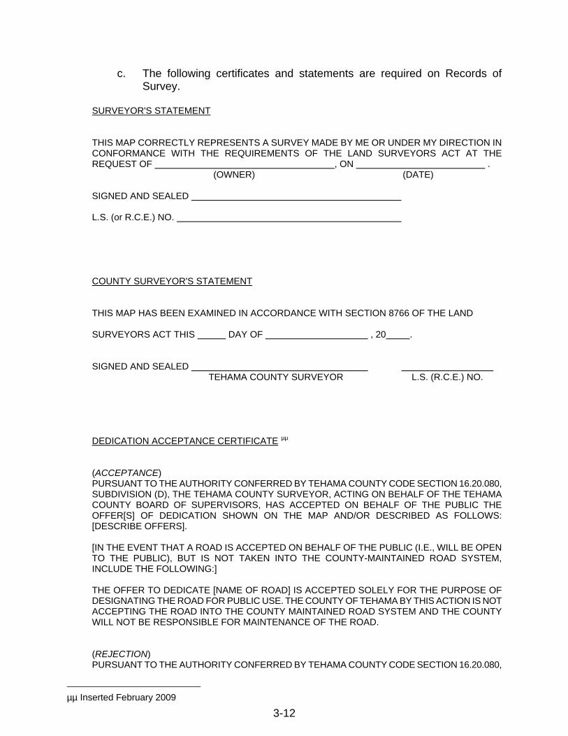
c. The following certificates and statements are required on Records of Survey.
SURVEYOR'S STATEMENT THIS MAP CORRECTLY REPRESENTS A SURVEY MADE BY ME OR UNDER MY DIRECTION IN CONFORMANCE WITH THE REQUIREMENTS OF THE LAND SURVEYORS ACT AT THE REQUEST OF , ON . (OWNER) (DATE) SIGNED AND SEALED L.S. (or R.C.E.) NO. COUNTY SURVEYOR'S STATEMENT THIS MAP HAS BEEN EXAMINED IN ACCORDANCE WITH SECTION 8766 OF THE LAND SURVEYORS ACT THIS DAY OF , 20 . SIGNED AND SEALED TEHAMA COUNTY SURVEYOR L.S. (R.C.E.) NO. DEDICATION ACCEPTANCE CERTIFICATE µµ (ACCEPTANCE) PURSUANT TO THE AUTHORITY CONFERRED BY TEHAMA COUNTY CODE SECTION 16.20.080, SUBDIVISION (D), THE TEHAMA COUNTY SURVEYOR, ACTING ON BEHALF OF THE TEHAMA COUNTY BOARD OF SUPERVISORS, HAS ACCEPTED ON BEHALF OF THE PUBLIC THE OFFER[S] OF DEDICATION SHOWN ON THE MAP AND/OR DESCRIBED AS FOLLOWS: [DESCRIBE OFFERS]. [IN THE EVENT THAT A ROAD IS ACCEPTED ON BEHALF OF THE PUBLIC (I.E., WILL BE OPEN TO THE PUBLIC), BUT IS NOT TAKEN INTO THE COUNTY-MAINTAINED ROAD SYSTEM, INCLUDE THE FOLLOWING:] THE OFFER TO DEDICATE [NAME OF ROAD] IS ACCEPTED SOLELY FOR THE PURPOSE OF DESIGNATING THE ROAD FOR PUBLIC USE. THE COUNTY OF TEHAMA BY THIS ACTION IS NOT ACCEPTING THE ROAD INTO THE COUNTY MAINTAINED ROAD SYSTEM AND THE COUNTY WILL NOT BE RESPONSIBLE FOR MAINTENANCE OF THE ROAD. (REJECTION) PURSUANT TO THE AUTHORITY CONFERRED BY TEHAMA COUNTY CODE SECTION 16.20.080,
µµ Inserted February 2009
3-12

3-13
SUBDIVISION (D), THE TEHAMA COUNTY SURVEYOR, ACTING ON BEHALF OF THE TEHAMA COUNTY BOARD OF SUPERVISORS, HAS REJECTED ON BEHALF OF THE PUBLIC THE OFFER[S] OF DEDICATION SHOWN ON THE MAP AND/OR DESCRIBED AS FOLLOWS: [DESCRIBE OFFERS]. [NOTE: SECTIONS 66463 AND 66477.2 OF THE GOVERNMENT CODE OF THE STATE OF CALIFORNIA PROVIDE THAT A REJECTED OFFER OF DEDICATION SHALL REMAIN OPEN AND SUBJECT TO FUTURE ACCEPTANCE BY THE COUNTY.] GARY B. ANTONE, LS 4734 TEHAMA COUNTY SURVEYOR Reg. Exp. ATTEST: Date Clerk of the Board of Supervisors SIGNED BY DEPUTY RECORDERS STATEMENT µ FILED THIS DAY OF , 20 , AT M., IN BOOK OF MAPS AT PAGE , AT THE REQUEST OF . TEHAMA COUNTY RECORDER SIGNED BY DEPUTY
Revised July 2008
µ Revised February 2009

CHAPTER 4
GRADING
AND
EROSION CONTROL
STANDARDS

CHAPTER 4 - GRADING AND EROSION CONTROL A. GENERAL
This chapter reflects the requirements of Tehama County Code Chapter 9.43 pertaining to grading and erosion control, which is the authority for implementation of the following process and procedure.
1. Purpose
The purpose of this chapter is to promote and protect the public safety, convenience, comfort, prosperity, protection of water quality, environmental health and watershed functions, general welfare and the county's natural resources by establishing minimum requirements for grading, excavating, and filling in order to:
a. Control erosion and sedimentation and prevent damage to off-site property
and streams, water-courses, and aquatic habitat;
b. Avoid creation of unstable slopes or filled areas;
c. Prevent impairment or destruction of potential leach fields for sewage disposal systems; and
d. Regulate de facto development caused by uncontrolled grading.
2. Definitions
For the purposes of this chapter, the following words and terms have the meanings indicated, unless the context in which any word or term is used or a specific provision of this code requires another meaning:
a. Director means the Director of the Tehama County Department of Public
Works.
b. Earth material means any soil, sand, gravel, decomposed granite, rock organic or mulch cover, or other natural material or fill.
c. Enforcing officer is the person or body so designated by the Tehama
County Board of Supervisors.
d. Grading means movement of any earth materials:
1) In excess of 250 cubic yards; or
Revised July 2008 4-1

2) Which is conducted within 250 feet of any pre-existing watercourse, or
3) To make a road, including but not limited to a temporary access road,
building pad, mobile home pad, well drilling pad or a new sewage disposal system when the installation of the sewage disposal system requires changes in the natural contour of the land; or
4) Which disturbs 10,000 square feet or more of surface area.
e. Grading permits are identified as either "Discretionary" or "Ministerial"
permits.
1) Discretionary Grading permits shall be required for any grading which will involve: 1) the movement of more than 2,000 cubic yards of earth, 2) the disturbance of more than five acres of earth material, or 3) is within 250 feet of any pre-existing watercourse. Notwithstanding the foregoing grading performed in connection with a detached single-family dwelling located on one parcel shall require a Ministerial Grading Permit. A Discretionary Grading Permit may be approved, conditionally approved, or denied by the Director, as provided in this Chapter. The issuance of all Discretionary grading permits is subject to CEQA review by the County.
2) Ministerial Grading Permits shall be required for any grading not
requiring a Discretionary Grading Permit.
f. Grading Standards are standards for grading, set forth in Section D of this Chapter.
g. Watercourse means any well-defined channel with distinguishable bed and
bank showing evidence of having contained flowing water indicated by deposit of rock, sand, gravel or soil, including but not limited to, streams as defined in Public Resources Code Section 4528(f). "Watercourse" also includes man-made watercourses.
3. Enforcing Officer Designated
In addition to any other enforcing officer designated by the Board of Supervisors, the Director is hereby designated as the enforcing officer. The Department of Public Works and every other County department shall provide technical assistance to any designated enforcing officer.
Revised July 2008 4-2
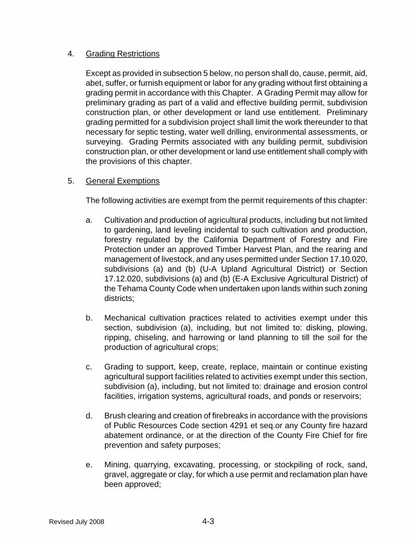
Revised July 2008 4-3
4. Grading Restrictions
Except as provided in subsection 5 below, no person shall do, cause, permit, aid, abet, suffer, or furnish equipment or labor for any grading without first obtaining a grading permit in accordance with this Chapter. A Grading Permit may allow for preliminary grading as part of a valid and effective building permit, subdivision construction plan, or other development or land use entitlement. Preliminary grading permitted for a subdivision project shall limit the work thereunder to that necessary for septic testing, water well drilling, environmental assessments, or surveying. Grading Permits associated with any building permit, subdivision construction plan, or other development or land use entitlement shall comply with the provisions of this chapter.
5. General Exemptions
The following activities are exempt from the permit requirements of this chapter:
a. Cultivation and production of agricultural products, including but not limited
to gardening, land leveling incidental to such cultivation and production, forestry regulated by the California Department of Forestry and Fire Protection under an approved Timber Harvest Plan, and the rearing and management of livestock, and any uses permitted under Section 17.10.020, subdivisions (a) and (b) (U-A Upland Agricultural District) or Section 17.12.020, subdivisions (a) and (b) (E-A Exclusive Agricultural District) of the Tehama County Code when undertaken upon lands within such zoning districts;
b. Mechanical cultivation practices related to activities exempt under this
section, subdivision (a), including, but not limited to: disking, plowing, ripping, chiseling, and harrowing or land planning to till the soil for the production of agricultural crops;
c. Grading to support, keep, create, replace, maintain or continue existing
agricultural support facilities related to activities exempt under this section, subdivision (a), including, but not limited to: drainage and erosion control facilities, irrigation systems, agricultural roads, and ponds or reservoirs;
d. Brush clearing and creation of firebreaks in accordance with the provisions
of Public Resources Code section 4291 et seq.or any County fire hazard abatement ordinance, or at the direction of the County Fire Chief for fire prevention and safety purposes;
e. Mining, quarrying, excavating, processing, or stockpiling of rock, sand,
gravel, aggregate or clay, for which a use permit and reclamation plan have been approved;

f. Operation of refuse disposal sites for which a valid permit has been issued
pursuant to Chapter 9.04 of the Tehama County Code;
g. Temporary excavation for installation or abandonment of underground storage tanks and associated piping when no permanent change is made in the existing terrain and the excavation is refilled;
h. Temporary trench or pit excavation for the purpose of installing
underground or overhead utilities;
i. Subsurface geologic exploration under the supervision of a licensed civil engineer, registered environmental health specialist, engineering geologist or archeologist;
j. The construction of pits for the containment of drilling fluids, when well
drilling is performed pursuant to Chapter 9.42 of the Tehama County Code;
k. Grading conducted during a civil or hazardous material emergency or natural disaster to relieve or correct conditions caused by such emergency or disaster or to make emergency firebreaks;
l. The removal and spreading of contaminated earth materials from
underground tank excavations performed in compliance with Chapter 9.30; Tehama County Code and;
m. Grading performed on public works projects by a governmental agency.
6. Other Regulations
a. The provisions of this Chapter shall be deemed to supplement
corresponding provisions of any of the technical codes adopted by Title 15 of the Tehama County Code relating to grading and erosion control. Where the provisions of any of the technical codes and this Chapter apply to the same subject matter, the provisions of this Chapter shall apply, unless the provisions of the technical codes are more stringent or more narrowly apply to the specific situation, in which case the specific provisions of the technical codes shall apply.
b. All grading and other work performed pursuant to a Grading Permit issued
in accordance with this Chapter shall comply with all applicable statutes, regulations, ordinances, and rules of all federal, state, and local agencies.
Revised July 2008 4-4
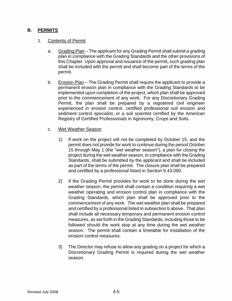
Revised July 2008 4-5
B. PERMITS
1. Contents of Permit
a. Grading Plan – The applicant for any Grading Permit shall submit a grading plan in compliance with the Grading Standards and the other provisions of this Chapter. Upon approval and issuance of the permit, such grading plan shall be included with the permit and shall become part of the terms of the permit.
b. Erosion Plan – The Grading Permit shall require the applicant to provide a
permanent erosion plan in compliance with the Grading Standards to be implemented upon completion of the project, which plan shall be approved prior to the commencement of any work. For any Discretionary Grading Permit, the plan shall be prepared by a registered civil engineer experienced in erosion control, certified professional soil erosion and sediment control specialist, or a soil scientist certified by the American Registry of Certified Professionals in Agronomy, Crops and Soils.
c. Wet Weather Season
1) If work on the project will not be completed by October 15, and the
permit does not provide for work to continue during the period October 15 through May 1 (the "wet weather season"), a plan for closing the project during the wet weather season, in compliance with the Grading Standards, shall be submitted by the applicant and shall be included as part of the terms of the permit. The closure plan shall be prepared and certified by a professional listed in Section 9.43.090.
2) If the Grading Permit provides for work to be done during the wet
weather season, the permit shall contain a condition requiring a wet weather operating and erosion control plan in compliance with the Grading Standards, which plan shall be approved prior to the commencement of any work. The wet weather plan shall be prepared and certified by a professional listed in subsection b above. That plan shall include all necessary temporary and permanent erosion control measures, as set forth in the Grading Standards, including those to be followed should the work stop at any time during the wet weather season. The permit shall contain a timetable for installation of the erosion control measures.
3) The Director may refuse to allow any grading on a project for which a
Discretionary Grading Permit is required during the wet weather season.

d. Ongoing Maintenance and Erosion Control – Each Grading Permit shall contain a plan for on-going maintenance of erosion control measures during the duration of the project and for three years after completion of the project, in compliance with the Grading Standards. The permittee shall be responsible for such maintenance. The maintenance plan shall be approved prior to the commencement of any work.
e. Compliance – When a Grading Permit is issued, the plans and
specifications required under this Chapter shall be endorsed in writing or stamped “APPROVED.” Plans that have been approved and included as part of the terms of a permit shall not be changed, modified, or altered without written authorization by the Director, and all work shall be done in accordance with the terms of the permit and the approved plans.
f. Indemnification – As a condition of issuance of any Grading Permit, the
permittee shall agree to defend, indemnify, and hold harmless, at the permittee's sole expense, the County and its employees, officers, directors, contractors and agents from and against any claim, action, or administrative proceeding challenging the County's decision to issue a permit to the permittee, any environmental review or absence thereof associated with the proposed grading, or the manner in which the County interprets or enforces the terms and conditions of this permit at any time, and to pay all losses, liabilities, damages, penalties, costs, awards, judgments, fees (including reasonable attorney’s fees) and expenses arising from such claim, action, or administrative proceeding. Counsel for the County in any such legal defense shall be selected by the County. As a further condition of issuance of any such permit, upon demand from the County, the permittee shall reimburse the County for any court costs and/or attorney's fees which the County may be required by a court to pay as a result of any claim, action, or administrative proceedings described in this Section. Neither the issuance of a permit, nor compliance with the conditions thereof, relieves the Permittee from any responsibility otherwise imposed by law for damage to persons or property, nor shall the issuance of any permit hereunder serve to impose any liability upon the County, its officers or employees for injury or damage to persons or property. Except with respect to the County's sole negligence or intentional misconduct, the Permittee shall indemnify, defend and hold harmless the County, its officers, agents, and employees, from any and all claims, demands, costs, expenses, including attorney's fees, judgments or liabilities arising out of the work or operations described in a Grading Permit issued hereunder.
2. Posting of Security
A Discretionary Grading Permit may require the posting of security in an amount sufficient to cover all corrective action or site restoration work and the cost of
Revised July 2008 4-6
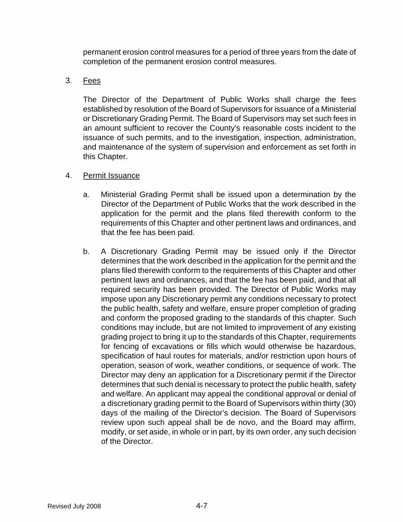
permanent erosion control measures for a period of three years from the date of completion of the permanent erosion control measures.
3. Fees
The Director of the Department of Public Works shall charge the fees established by resolution of the Board of Supervisors for issuance of a Ministerial or Discretionary Grading Permit. The Board of Supervisors may set such fees in an amount sufficient to recover the County's reasonable costs incident to the issuance of such permits, and to the investigation, inspection, administration, and maintenance of the system of supervision and enforcement as set forth in this Chapter.
4. Permit Issuance
a. Ministerial Grading Permit shall be issued upon a determination by the
Director of the Department of Public Works that the work described in the application for the permit and the plans filed therewith conform to the requirements of this Chapter and other pertinent laws and ordinances, and that the fee has been paid.
b. A Discretionary Grading Permit may be issued only if the Director
determines that the work described in the application for the permit and the plans filed therewith conform to the requirements of this Chapter and other pertinent laws and ordinances, and that the fee has been paid, and that all required security has been provided. The Director of Public Works may impose upon any Discretionary permit any conditions necessary to protect the public health, safety and welfare, ensure proper completion of grading and conform the proposed grading to the standards of this chapter. Such conditions may include, but are not limited to improvement of any existing grading project to bring it up to the standards of this Chapter, requirements for fencing of excavations or fills which would otherwise be hazardous, specification of haul routes for materials, and/or restriction upon hours of operation, season of work, weather conditions, or sequence of work. The Director may deny an application for a Discretionary permit if the Director determines that such denial is necessary to protect the public health, safety and welfare. An applicant may appeal the conditional approval or denial of a discretionary grading permit to the Board of Supervisors within thirty (30) days of the mailing of the Director's decision. The Board of Supervisors review upon such appeal shall be de novo, and the Board may affirm, modify, or set aside, in whole or in part, by its own order, any such decision of the Director.
Revised July 2008 4-7

Revised July 2008 4-8
5. Permit Time Limits
Grading operations shall be started within one (1) year from the effective date of the Grading Permit unless extended by the Director for good cause, or the permit shall expire and a new application shall be required. “Good cause” shall include, but not be limited to, delays in obtaining required permits from other agencies provided the applicant has diligently pursued said permits. The Grading Permit shall be valid for a period of three (3) years.
6. Validity
The issuance of a Grading Permit or approval of plans and specifications shall not be construed as an approval of any violation of the provisions of this Chapter or of any other applicable laws, ordinances, rules or regulations.
7. Transfer of Permit
No Grading Permit issued under this section may be transferred or assigned in any manner whatsoever, without the express written consent of the Director.
8. Modification of Permit
Any person holding a valid Grading Permit may file an application to modify the permit. The application shall be filed and processed in the same manner as an application for a new Grading Permit, and shall emphasize changes to the grading activity. The Director’s action authorizing a modification to a discretionary grading permit may include changes to conditions of the original Grading Permit.
9. Suspension or Revocation of Permit
The Director may, in writing, suspend or revoke a Grading Permit issued under the provisions of this Chapter when the permit is issued in error or on the basis of incorrect information supplied, or in violation of any law, ordinance, or regulation, or any of the provisions of this Chapter.
C. ENFORCEMENT
1. Stop Work Order
Whenever the enforcing officer determines that any grading is occurring or has occurred in violation of the provisions of this chapter, without a Grading Permit, in violation of the terms and conditions for the permit, or in violation of the Grading Standards or other applicable law, or without compliance with the conditions of any other applicable permit or governmental approval to perform

the work, the enforcing officer shall issue a stop order directing that the violation cease immediately. The order shall state the nature of the violation and that it is deemed to be a nuisance and shall contain references to applicable provisions of law, the Grading Standards or conditions of approval upon which the enforcing officer based his determination. The order shall include a statement of any corrective action or restoration work the enforcing officer deems necessary to abate the condition. It shall be unlawful and a violation of this code for any person to resume grading activities that were ordered to be stopped by the enforcing officer, unless the enforcing officer has first required and the person has agreed to any necessary corrective measures, and the enforcing officer has authorized resumption of work. The person to whom a stop work order is issued may appeal the issuance of the order to the Board of Supervisors within thirty (30) days of issuance of the order, but the filing of such appeal shall not permit the resumption of grading activities that were ordered to be stopped by the enforcing officer. The Board of Supervisors may affirm, modify, or set aside, in whole or in part, by its own order, any stop work order of the Director.
2. Administrative Penalties
In addition to any other penalty, each violation of this chapter may be subject to an administrative penalty of up to $5,000 per day. The administrative penalty may be imposed via the administrative process set forth in this subdivision, as provided in Government Code section 53069.4, or may be imposed by the court if the violation requires court enforcement without an administrative process. In the case of a continuing violation, if the violation does not create an immediate danger to health or safety, the enforcing officer or the Court shall provide for a reasonable period of time, not to exceed three (3) days, for the person responsible for the violation to correct or otherwise remedy the violation prior to the imposition of administrative penalties. In determining the amount of the administrative penalty, the enforcing officer or the Court shall take into consideration the nature, circumstances, extent, and gravity of the violation or violations, any prior history of violations, the degree of culpability, economic savings, if any resulting from the violation, and any other matters justice may require. An order imposing an administrative penalty by the enforcing officer shall become effective upon issuance, and payment shall be made to the County within thirty (30) days, unless the person to whom the order is issued appeals to the Board of Supervisors for review of the order within that time. If the person to whom the order is issued appeals the enforcing officer's decision to impose an administrative penalty to the Board of Supervisors, the person shall be notified by certified mail when the matter has been set for hearing. After the hearing, the Board of Supervisors may affirm, modify, or set aside, in whole or in part, by its own order, any order of the enforcing officer imposing an administrative penalty. Any order of the Board of Supervisors shall become effective upon issuance thereof and shall be served by certified mail upon the appellant. Payment of an administrative penalty specified in the Board of Supervisors’ order shall be made
Revised July 2008 4-9

to the County within thirty (30) days of service of the order. In addition to any other remedy, the County may prosecute a civil action through the Office of the County Counsel to collect any administrative penalties imposed pursuant to this Section.
3. Civil Enforcement
Violation of this chapter is hereby declared to be a public nuisance and such violations may be redressed, enjoined, and abated by civil action through the Office of the County Counsel. If, in the judgment of the enforcing officer, the violation requires court enforcement without an administrative process, County Counsel may also seek the administrative penalties provided by subsection 2 above.
4. Criminal Penalties
Any person violating any provision of this Chapter shall be guilty of a misdemeanor. Each such person shall be charged with a separate offense for each and every day or portion thereof during which any violation of this Chapter is committed, continued, or permitted. Upon conviction of any such violation, such person shall be punishable by a fine of not more than one thousand dollars ($1,000.00) or by imprisonment in the county jail for not more than six months, or by both such fine and imprisonment.
5. Refusal to Issue Permits
No department, commission or employee of the county of Tehama vested with the duty or authority to issue or approve permits, licenses or other entitlements shall do so when there is an outstanding violation of this chapter, as determined by the Director, involving the premises to which the pending application pertains. The authority to deny shall apply whether the applicant was the occupant or owner of record at the time of such violation or whether the applicant is either the current occupant or owner of record or a vendor of the current owner of record pursuant to a contract of sale of the real property, with or without actual or constructive knowledge of the violation at the time he or she acquired his or her interest in such real property. Upon notification by a Director that such a violation exists, all departments, such commissions, and employees shall refuse to issue permits or licenses or entitlements involving the premises except those necessary to abate such violation. The Director may waive the provisions of this section regarding refusal to issue if he or she determines such waiver to be required to allow necessary or desirable remedial, protective or preventative work.
Revised July 2008 4-10

Revised July 2008 4-11
6. Cumulative Remedies
All remedies provided for herein are cumulative and not exclusive, and are in addition to any other remedy or penalty provided by law
D. GRADING STANDARDS
1. Purpose and Limitations
The purpose of these standards is to safeguard life, limb, property, environmental health and water quality and the public welfare by regulating grading on private property.
2. Definitions
As used in this Section, and unless the context in which a word is used requires a different meaning, the following terms have the meanings indicated.
a. Definitions are as follows:
1) Approval: a written engineering or geological opinion concerning the
progress and completion of the work.
2) As Graded: the surface conditions extent on completion of grading.
3) Bedrock: in-place solid rock.
4) Bench: a relatively level step excavated into earth material on which fill is to be placed.
5) Borrow: earth material acquired from an off-site location for use in
grading on a site.
6) Civil Engineer: a professional engineer registered in the state to practice in the field of civil works.
7) Civil Engineering: the application of the knowledge of the forces of
nature, principles of mechanics and the properties of the materials to the evaluation, design and construction of civil works for the beneficial uses of mankind.
8) Compaction: densification of a fill by mechanical means.
9) Earth Material: any soil, sand, gravel, decomposed granite, or other
natural material or fill or any combination thereof.

10) Engineered Grading: grading in excess of 5,000 cubic yards or in
variance with the Grading Standards.
11) Engineering Geologist: a geologist experienced and knowledgeable in engineering geology.
12) Engineering Geology: the application of geologic knowledge and
principles in the investigation and evaluation of naturally occurring rock and soil for use in the design of civil works.
13) Engineering Geology Report: a report prepared by an engineering
geologist that includes an adequate description of the geology of the site, conclusions and recommendations regarding the effect of geological conditions on the proposed development, and opinions and recommendations covering the adequacy of sites to be developed by the proposed grading.
14) Erosion: the wearing away of the ground surface as a result of the
movement of wind, water, ice or a combination thereof.
15) Excavation: the mechanical removal of earth material.
16) Fill: a deposit of earth material placed by artificial means.
17) Grade: the vertical location of the ground surface.
18) Existing Grade: the grade prior to grading.
19) Rough Grade: the stage at which the grade approximately conforms to the plan.
20) Finish Grade: the final grade of the site which conforms to the plan.
21) Grading: any excavating or filling or combination thereof.
22) Key: a designed compacted fill placed in a trench excavated in earth
material beneath the toe of a proposed fill slope.
23) Site: any lot or parcel of land or contiguous combination thereof, under the same ownership, where grading is performed or permitted.
24) Slope: an inclined ground surface, the inclination of which is
expressed as a ratio of horizontal distance to vertical distance.
Revised July 2008 4-12

25) Soil: naturally occurring surficial deposits overlying bedrock.
26) Soil Engineer: a civil engineer experienced and knowledgeable in the practice of soil engineering.
27) Soil Engineering: the application of the principles of soil mechanics in
the investigation, evaluation and design of civil works involving the use of earth materials and the inspection and testing of the construction thereof.
28) Soil Engineering Report: a report prepared by a soil engineer that
includes data regarding the nature, distribution and strength of existing soils, conclusions and recommendations for grading procedures and design criteria for corrective measures when necessary, and opinions and recommendations covering adequacy of sites to be developed by the proposed grading.
29) Terrace: a relatively level step constructed in the face of a graded
slope surface for drainage and maintenance purposes.
30) Vertical Height: the vertical distance between the toe of a slope and a line level with the top of that slope.
3. Cuts
a. General. Unless otherwise recommended in a soil engineering and/or
engineering geology report, cuts shall conform to the provisions of this subsection.
b. Slope. The slope of cut surfaces shall be no steeper than is safe for the
intended use. Cut slopes shall be no steeper than two horizontal to one vertical unless a soil engineering report is submitted and approved by the Enforcing Officer substantiating the need for a steeper cut slope, and a Discretionary Grading Permit is obtained in accordance with this Chapter.
c. Drainage and Terracing. Drainage and terracing shall be provided as
required by Subsection 6.
4. Fills
a. General – Unless otherwise recommended in an approved soil engineering report, fills shall conform to the provisions of this subsection.
Revised July 2008 4-13

b. Fill Location – Fill slopes shall not be constructed on natural slopes steeper than two to one. Fill slopes in excess of 30% shall be constructed under the direction of a soil engineer.
c. Preparation of Ground – The ground surface shall be prepared to receive
fill by removing vegetation, non-complying fill, topsoil and other unsuitable materials and scarifying to provide a bond with the new fill, and where slopes are steeper than five to one (5-1), and the height is greater than five (5) feet, by benching into sound bedrock or other competent material. The bench under the toe of a fill on a slope steeper than five to one (5-1) shall be at least ten (10) feet wide. The area beyond the toe of fill shall be sloped for sheet overflow or a paved drain shall be provided. Where fill is to be placed over a cut, the bench under the toe of fill shall be at least ten (10) feet wide but the cut must be made before placing fill.
d. Compaction – All fills shall be compacted to a minimum of ninety (90)
percent of maximum density. Compaction tests shall be conducted by a California registered Civil Engineering or Geotechnical Engineering Company, or by an approved materials testing laboratory. Compaction tests shall be done in compliance with California test methods 216 and 231.
e. Slope – The slope of fill surfaces shall be no steeper than is safe for the
intended use.
f. Drainage and Terracing – Drainage and terracing shall be provided and the area above fill slopes and the surfaces of terraces shall be graded and paved as required by Subsection 6.
5. Setbacks
a. General – The setbacks and other restrictions are minimum and may be
increased by the recommendation of a civil engineer, soils engineer or engineering geologist, if necessary for safety and stability or to prevent damage of adjacent properties from deposition or erosion or to provide access for slope maintenance and drainage. Retaining walls may be used to reduce the required setbacks.
b. Setbacks from Property Lines – The tops of cuts and toes of fill slopes shall
be set back from the outer boundaries of the property line, including slope areas and easements, in accordance with DWG # 0920.
c. Design Standards for Setbacks – Setbacks between graded areas (cut or
fill) and structures shall be provided in accordance with DWG # 0920.
6. Drainage and Terracing
Revised July 2008 4-14
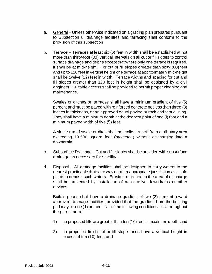
a. General – Unless otherwise indicated on a grading plan prepared pursuant
to Subsection 8, drainage facilities and terracing shall conform to the provision of this subsection.
b. Terrace – Terraces at least six (6) feet in width shall be established at not
more than thirty-foot (30) vertical intervals on all cut or fill slopes to control surface drainage and debris except that where only one terrace is required, it shall be at mid-height. For cut or fill slopes greater than sixty (60) feet and up to 120 feet in vertical height one terrace at approximately mid-height shall be twelve (12) feet in width. Terrace widths and spacing for cut and fill slopes greater than 120 feet in height shall be designed by a civil engineer. Suitable access shall be provided to permit proper cleaning and maintenance.
Swales or ditches on terraces shall have a minimum gradient of five (5) percent and must be paved with reinforced concrete not less than three (3) inches in thickness, or an approved equal paving or rock and fabric lining. They shall have a minimum depth at the deepest point of one (l) foot and a minimum paved width of five (5) feet.
A single run of swale or ditch shall not collect runoff from a tributary area exceeding 13,500 square feet (projected) without discharging into a downdrain.
c. Subsurface Drainage – Cut and fill slopes shall be provided with subsurface
drainage as necessary for stability.
d. Disposal – All drainage facilities shall be designed to carry waters to the nearest practicable drainage way or other appropriate jurisdiction as a safe place to deposit such waters. Erosion of ground in the area of discharge shall be prevented by installation of non-erosive downdrains or other devices.
Building pads shall have a drainage gradient of two (2) percent toward approved drainage facilities, provided that the gradient from the building pad may be one (1) percent if all of the following conditions exist throughout the permit area:
1) no proposed fills are greater than ten (10) feet in maximum depth, and
2) no proposed finish cut or fill slope faces have a vertical height in
excess of ten (10) feet, and
Revised July 2008 4-15

3) no existing slope faces, which have a slope face steeper than 10:1 horizontal to vertical, shall have a vertical height in excess of ten (10) feet.
e. Interceptor Drains – Paved interceptor drains or properly designed rock
channels lined with fabric shall be installed along the top of all cut slopes where the tributary drainage area above slopes towards the cut and has a drainage path greater than forty (40) feet measured horizontally. Interceptor drains shall be paved with a minimum of three (3) inches of concrete or gunite and reinforced. They shall have a minimum depth of twelve (12) inches and a minimum paved width of thirty (30) inches measured horizontally across the drain. Rock and fabric lined channels shall be designed by a soil engineer and must withstand the maximum potential flow and retain its integrity.
7. Erosion Control
When construction activities propose to disturb areas of existing vegetation and ground cover by grading, effective erosion and sediment control measures shall be employed.
a. Erosion Control Plan – Whenever a grading permit requires an erosion
control plan, it shall be submitted with the grading plan as per stipulations in the grading permit.
If the site or portion of the site is planned to be idle for more than 45 days, then vegetative stabilization must be accomplished within seven (7) days. The wet weather plan shall include a plan for the immediate (within 24 hours of the first forecast of a storm front) installation of emergency erosion control measures.
b. Design Standards – Best management practices shall be employed.
8. Grading Plan and Inspection
All engineered grading requires a grading plan prepared by a civil engineer prior to commencement of work.
The civil engineer who prepares a grading plan shall incorporate all recommendations from the soil engineering report and any engineering geology report into the grading plan. He shall also be responsible for the professional inspection and approval of the grading within his area of technical specialty. This responsibility shall include, at a minimum, grade and drainage of the development area.
Revised July 2008 4-16

Revised July 2008 4-17
A soil engineering report shall be prepared for each grading plan prepared by a civil engineer.
The soil engineer's area of responsibility shall include, at a minimum, the professional inspection and approval concerning the preparation of ground to receive fills, testing for required compaction, stability of all finish slopes and the design of buttress fills, where required, incorporating any data supplied by an engineering geologist.
If an engineering geologist is retained for the work, his area of responsibility shall include, at a minimum, professional inspection and approval of the adequacy of natural ground for receiving fills and the stability of cut slopes with respect to geological matters, and the need for subdrains or other ground water drainage devices. He shall report his findings to the soil engineer and the civil engineer for engineering analysis. If an engineering geologist is not retained, the civil engineer who prepares the grading plan shall assume the responsibilities of the engineering geologist.
9. Archeological Sites/Cultural Resource Protection
If, in the course of development, any archeological or cultural remains are encountered, work shall cease and a qualified archeologist contacted immediately.
a. Cultural Resources Protection – If any potential prehistoric, protohistoric,
and historic cultural resources are encountered during any phase of the project operations, all work should cease in the area of the find pending examination of the site and materials by a qualified archaeologist.

CHAPTER 5
SEWAGE
DISPOSAL
STANDARDS
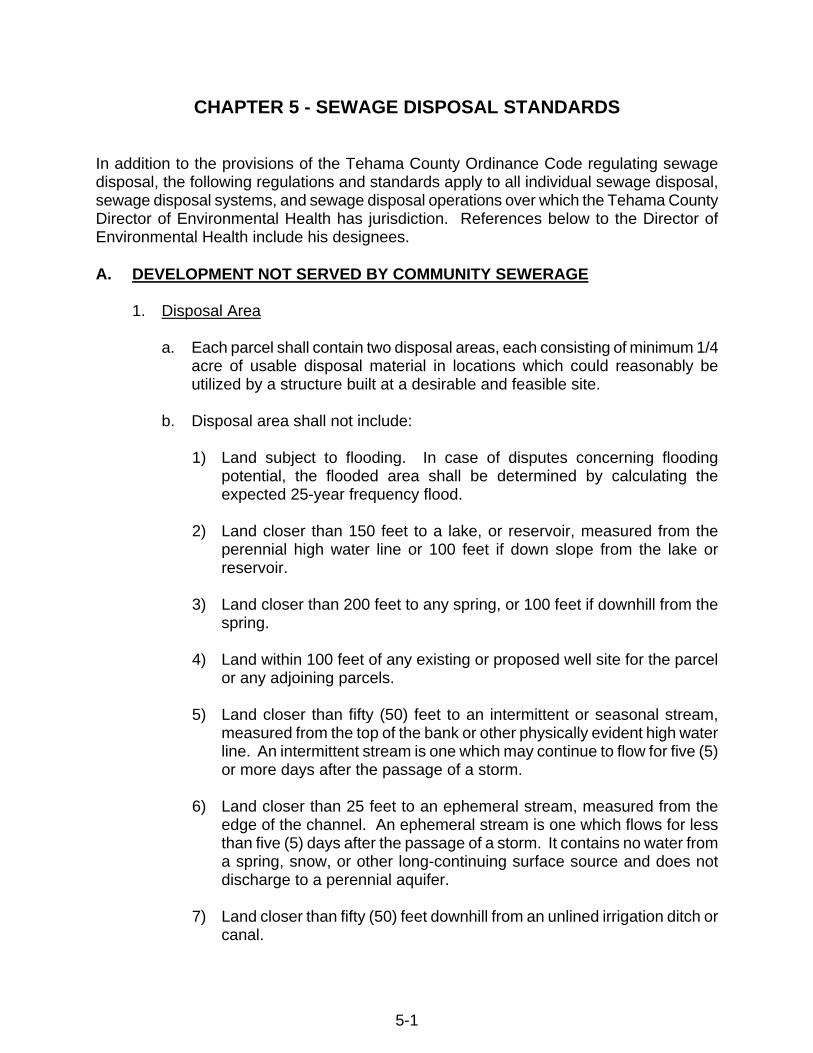
CHAPTER 5 - SEWAGE DISPOSAL STANDARDS In addition to the provisions of the Tehama County Ordinance Code regulating sewage disposal, the following regulations and standards apply to all individual sewage disposal, sewage disposal systems, and sewage disposal operations over which the Tehama County Director of Environmental Health has jurisdiction. References below to the Director of Environmental Health include his designees. A. DEVELOPMENT NOT SERVED BY COMMUNITY SEWERAGE
1. Disposal Area
a. Each parcel shall contain two disposal areas, each consisting of minimum 1/4 acre of usable disposal material in locations which could reasonably be utilized by a structure built at a desirable and feasible site.
b. Disposal area shall not include:
1) Land subject to flooding. In case of disputes concerning flooding
potential, the flooded area shall be determined by calculating the expected 25-year frequency flood.
2) Land closer than 150 feet to a lake, or reservoir, measured from the
perennial high water line or 100 feet if down slope from the lake or reservoir.
3) Land closer than 200 feet to any spring, or 100 feet if downhill from the
spring.
4) Land within 100 feet of any existing or proposed well site for the parcel or any adjoining parcels.
5) Land closer than fifty (50) feet to an intermittent or seasonal stream,
measured from the top of the bank or other physically evident high water line. An intermittent stream is one which may continue to flow for five (5) or more days after the passage of a storm.
6) Land closer than 25 feet to an ephemeral stream, measured from the
edge of the channel. An ephemeral stream is one which flows for less than five (5) days after the passage of a storm. It contains no water from a spring, snow, or other long-continuing surface source and does not discharge to a perennial aquifer.
7) Land closer than fifty (50) feet downhill from an unlined irrigation ditch or
canal.
5-1
8) Land closer than fifty (50) feet uphill from an existing or proposed cut.
9) Land with a grade steeper than thirty (30) percent.
10) Filled land, unless the fill is engineered for sewage disposal and
approved by the Tehama County Director of Environmental Health.
11) Dredger tailings.
12) Gravel bars of very pervious materials adjoining a stream or body of water.
13) Land used for road or utility easements. Overhead utility easements
may be included if the utility, entity or agency holding the easement gives a permanent and unconditional release, easement or license for sewage disposal within the easement.
c. See Table 1 for setback distances for sewage disposal systems.
2. Disposal Material Characteristics
Usable disposal material has both of the following characteristics:
a. Percolation rates greater than five (5) and less than sixty (60) minutes per
inch when tests are conducted by the method specified in the Manual of Septic Tank Practice, U.S. Department of Health and Human Services.
b. Percolation rates between 60 m.p.i. and no greater than 120 m.p.i. maybe
approved only if specially designed by a registered civil engineer, geologist or registered environmental health specialist.
c. Depth to a seasonal high water table shall have at least five (5) feet of
separation between trench bottom for lots of less than ten (10) acres and at least three (3) feet for lots greater than ten (10) acres.
3. Percolation Test, Test Pits and Groundwater Monitoring
a. Percolation Tests.
Three (3) percolation tests representative of the disposal area shall be conducted on each proposed disposal area by the method in the Manual of Septic Tank Practice.
5-2

b. Test Pits.
At least one test pit shall be excavated on each lot. It shall be at least two (2) feet wide and eight (8) feet deep. It shall slope towards one end at a rate no greater than 3:1. The soil profile shall be logged by a person qualified to perform percolation tests and witnessed by Tehama County Environmental Health Department.
c. Groundwater Monitoring.
1) The height of the seasonal high groundwater shall be determined by wet
weather testing when any of the following is present:
a) Vegetation tolerant of, or indicative of, a high water table present on or in the vicinity of the parcel.
b) High groundwater has previously been found in the vicinity.
c) The test pits show cracked or creviced formations but no clear
delineation of the top of the water table.
d) Other conditions or historical data that preclude accurate determination of the groundwater levels by dry weather observations.
e) Free water from seepage is observed in the test pit.
2) The height of seasonal high groundwater shall be determined by actual
measurements of observation wells during periods of maximum soil moisture content, after eighty (80) percent of normal precipitation has occurred to meet or exceed field capacity of the soil, and produce a response in observation wells acceptable to the Tehama County Director of Environmental Health.
a) Direct Observation:
The design for constructing an observation well is shown on STD Plan 0963, and Tehama County Bulletin #1.
Measurements shall be taken at the times and intervals specified by the Tehama County Director of Environmental Health in response to local conditions. Except as the Tehama County Director of Environmental Health may otherwise direct, measurements (excluding land within the Anderson Cottonwood Irrigation District (A.C.I.D.)) shall be taken at approximately monthly intervals from January 1 to April 30. Land requiring groundwater
5-3

monitoring caused by A.C.I.D. irrigation water and within the A.C.I.D. shall have monthly measurements beginning May 1 and ending August 31.
d. All of the above testing shall be done by, or under the supervision of a
qualified registered civil engineer, registered geologist, registered environmental health specialist, certified engineering geologist, or soil scientist certified by the American Registry of Certified Professionals in Agronomy, Crops and Soils, or by a qualified testing laboratory approved by the Office of the State Architect.
e. The results of all percolation tests and groundwater monitoring shall be
reported and the logs of all excavations shall be submitted to the Tehama County Director of Environmental Health and shall be accompanied by a plot plan to scale showing the test, well and pit locations. The map shall include the topography in the 1/4 acre disposal area at five (5) foot contour intervals. The Tehama County Director of Environmental Health may disregard any test or log that, in his opinion, does not represent the soil conditions of the parcel.
f. Lots Created for Uses which will not Generate Liquid Wastes.
1) This parcel was created utilizing agricultural exemption. No soils study
was conducted for the creation of this parcel. Each of these parcels shall be identified on the recorded map with this statement: “This parcel is not approved for any use that will generate liquid wastes”. No permit to dispose of sewage or other liquid waste generated by the use of this property will be issued until applicable provisions of state and local law and the Tehama County Sewage Disposal Standards have been compiled with.
OR
2) This parcel was created utilizing agricultural exemption. No soils study
was conducted for the creation of this parcel. Each of these parcels shall be identified on the recorded map with this statement: “Knowledge of soil conditions in this region/area indicates characteristics that may not be compatible with the Tehama County On-Site Sewage Disposal Code. This parcel is not approved for any use that will generate liquid wastes”. No permit to dispose of sewage or other liquid waste generated by the use of this property will be issued until applicable provisions of state and local law and the Tehama County Sewage Disposal Standards have been compiled with.
5-4

4. Subdivisions
Whenever any subdivision of property results in the creation of any parcel or parcels less than one acre in size, the subdivider shall be required to construct a community sanitary sewer system to serve all of the parcels within the subdivision and to form a public entity (which may be a mutual water company) to operate and maintain the system, unless the approving authority grants a specific waiver of this requirement after consultation with the Regional Water Quality Control Board. Seepage pits are not considered an appropriate sewage disposal method for newly created lots.
5. Maps
a. Tentative.
b. All tentative maps shall show for each parcel the location, boundaries and
calculated acreage of the disposal area(s) as determined by the procedures of A3. The test results shall be submitted concurrently with the tentative land division application. If individual wells are proposed, the map shall show all existing and proposed well sites. The map shall be to scale and show topography in the 1/2 acre disposal area at five (5) feet contour intervals and location of the test pits, percolation tests, and piezometers.
c. Final and Parcel Maps.
d. For each parcel, the area(s) qualifying as disposal area shall be clearly
delineated and labeled on the final or parcel map. If recordation of a parcel map is waived and developable parcels are proposed, a plot plan showing equivalent information shall be attached as an exhibit to, and recorded with, the notice of approval of waiver of parcel map. The face of each map or plot plan shall be annotated: "An onsite sewage disposal system shall be located only within the disposal area indicated for each parcel unless an alternative site is specifically approved by the Tehama County Director of Environmental Health." If individual wells are proposed, the map shall show all existing and proposed well sites.
e. All developments under this section shall comply with these standards unless
exceptions are granted in accordance with Chapter 16.32, Tehama County Code.
5-5

B. CONSTRUCTION AND INSTALLATION
The following requirements apply to all lots regardless of when or how created.
1. Onsite Sewage Disposal (General)
a. Where permitted by Section 1101 of the CPC, a building or mobile home sewer may be connected to a sewage disposal system complying with the provisions of these Standards if a sewage disposal permit is first obtained. The type of systems shall be determined on the basis of location, soil porosity and the groundwater level and shall be designed to receive all sanitary sewage from the property. Unless another design or method is approved by the Tehama County Director of Environmental Health, the system shall consist of a septic tank with effluent discharging into a subsurface disposal field.
b. Disposal systems shall be designed to utilize the most porous or absorbent
and aerobic portions of the soil formation. Where the groundwater level extends to within three (3) feet minimum separation on lots greater than ten (10) acres and five (5) feet minimum separator on lots less than ten (10) acres where the upper soil is porous and the underlying stratum is rock or impervious soil, a septic tank and disposal field system may be installed but no seepage pit will be permitted in any event.
c. All onsite sewage disposal systems shall be designed so that additional
subsurface disposal fields, equivalent to at least 100 percent of the required area of the original system, may be installed if the original system cannot absorb and treat all the sewage. No parcel shall be divided and no structure shall be erected or constructed if to do so would impair the usefulness of the 100 percent expansion area for its intended purpose.
d. No property shall be improved or used in excess of its capacity to properly
absorb sewage effluent in the quantities and by the means provided in these Standards.
e. When the Tehama County Director of Environmental Health finds
insufficient lot area or improper soil conditions for adequate sewage disposal for the use proposed, no sewage disposal, building or mobile home installation permit shall be issued and no onsite sewage disposal shall be permitted. Where space or soil conditions are critical, no permit shall be issued until engineering data and test reports have been submitted to and approved by the Tehama County Director of Environmental Health. The Tehama County Director of Environmental Health may approve a variance as to the location of any disposal field shown on a map or plot plan approved under Subsection A above if he finds that new information and public health and safety require the variance.
5-6
2. Area of Disposal Fields and Seepage Pits
The minimum effective absorption area in disposal fields in square feet of trench bottom and sidewall, and in seepage pits in square feet of side wall, shall be predicated on anticipated daily sewage flow in gallons, and type of soil found in the excavation.
a. For disposal fields, a minimum of 150 square feet of trench bottom shall be
provided for each system, exclusive of all hardpan, rock, clay and other impervious formations. For large, specially-designed and approved systems, side wall area in excess of the required twelve (12) inches and not to exceed 36 inches below the leach line may be added to the square feet trench bottom area when computing absorption areas.
b. For seepage pits, the required wall area of the pit or pits shall be
determined from the results of percolation tests made and interpreted as directed by the Tehama County Director of Environmental Health.
3. Septic Tanks
a. Plans for all septic tanks shall be submitted to the Tehama County Director
of Environmental Health for approval and shall show all dimensions, reinforcing, structural calculations and such other pertinent data as may be required. Independent laboratory tests and calibrations shall be provided on prefabricated septic tanks as required by the Tehama County Director of Environmental Health.
b. Septic tanks shall be water-tight and constructed of sound and durable
materials that are not subject to excessive corrosion or decay. Wooden septic tanks are prohibited. Each tank shall be structurally designed to withstand all anticipated earth or other loads and shall be installed level and on a solid bed.
c. Concrete covers shall be reinforced with steel reinforcing bars and poured-
in-place covers shall be reinforced with 1/2-inch steel bars on not more than 20-inch centers. All covers shall be capable of supporting an earth load of not less than 300 pounds per square foot when the maximum coverage does not exceed three feet.
d. The minimum wall thickness of any steel septic tank shall be No. 12 U.S.
gauge (.109 in.) and each steel tank shall be protected from corrosion both externally and internally by an approved bituminous coating or by other means acceptable to the Tehama County Director of Environmental Health.
5-7

e. Septic tank design shall be such as to produce a clarified effluent and shall provide adequate space for sludge and scum accumulations consistent with the proposed use.
f. Septic tanks shall have a minimum of two (2) compartments. The inlet
compartment of any septic tank shall account for two-thirds of the total capacity of the tank and have a liquid capacity of not less than 1,200 gallons, and shall be at least three (3) feet in width and five (5) feet in length. Liquid depth shall be not less than two (2) feet and six (6) inches. The secondary compartment of any septic tank shall have a capacity of one-third of the total capacity of the tank.
g. Access to each septic tank shall be provided by at least two (2) manholes
twenty (20) inches in minimum dimension or by an equivalent removable cover slab. One manhole shall be located over the inlet and one over the outlet. Whenever a first compartment exceeds twelve (12) feet in length, an additional manhole shall be provided over the baffle wall. Septic tanks installed under concrete paving or blacktop shall have the required manholes accessible by either extending the manhole openings to grade in a manner acceptable to the Tehama County Director of Environmental Health, or by providing a removable concrete or other approved section, not less than twenty (20) inches in the least dimension, in the concrete paving or blacktop and located directly over the required manholes.
h. The inlet and outlet pipe or baffle shall extend four (4) inches above and at
least twelve (12) inches below the water surface. The invert of the inlet pipe shall be at a level not less than two (2) inches above the invert of the outlet pipe.
i. Inlet and outlet pipe fittings or baffles and compartment partitions shall have
a free vent area equal to the required cross-sectional area of the house sewer or private sewer discharging into the tank to provide free ventilation above the water surface from the disposal field or seepage pit through the septic tank, house sewer and stack to the outer air.
4. Disposal Fields
a. Distribution lines shall be constructed of materials approved by the Tehama
County Director of Environmental Health provided that sufficient openings are available for distribution of the effluent into the trench area.
b. Before drain lines are laid, gravel, or similar filter materials clean in
appearance and varying in size from 3/4 inch to 2-1/2 inches and otherwise acceptable to the Tehama County Director of Environmental Health shall be placed in the trench to the depth and grade required by this paragraph.
5-8

c. Where two (2) or more drain lines are installed, an approved distribution box of sufficient size to receive lateral lines shall be constructed at the head of each disposal field. The inverts of the inlet shall be at least one (1) inch above the outlets. Suitable baffles shall be provided to insure equal flow. Distribution boxes shall be installed in natural or compacted soil.
d. Connections between a septic tank and a distribution box, or between a
distribution box and seepage pit or drain field, or between seepage pits shall be laid with approved watertight joints on natural ground or compacted fill.
e. Automatic siphon or dosing tanks shall be installed when required or as
permitted by the Director of Environmental Health.
f. Disposal fields shall be constructed as follows:
Maximum length of each line..................................... 100 feet Minimum bottom width of trench ............................... 24 inches Minimum spacing of lines (edge to edge).................. 6 feet Minimum depth of earth cover over lines .................. 12 inches Maximum grade of lines ............................................ 4”/100’ Minimum grade of trench .......................................... Level Maximum grade of trench ......................................... 4”/100’ Minimum usable material below trench bottom ......... 12 inches Minimum filter material under drain lines................... 12 inches Minimum filter material over drain lines..................... 2 inches Maximum filter material under drain lines.................. 36 inches Maximum distance drain pipe to edge of trench........ 18 inches
g. A disposal field shall not be installed in filled ground.
h. Straw, newspaper, untreated building paper or similar materials shall be
placed over filter materials in leach lines or seepage pits prior to backfilling.
5. Seepage Pits
No seepage pit may be located in areas where individual wells are within 150 feet. Seepage pits are to be used only as a last resort when no other method of disposal is likely to function properly. No seepage pit may be constructed, maintained or used for sewage disposal unless the Tehama County Director of Environmental Health finds in each case that the use of the pit or pits will not cause a health hazard directly or indirectly. Seepage pits shall be constructed to the following standards:
5-9

a. Each seepage pit above any stratum containing water which is used or is usable as a source of domestic supply shall be separated from that stratum by an impervious stratum.
b. As soon as the pit is completed, a perforated pipe at least four (4) inches in
diameter shall be extended from the bottom to the level of the forthcoming concrete seal. The pit shall then be filled with filter material conforming to the specifications in paragraph 4 above.
c. Percolation tests may be conducted to demonstrate the absorptive capacity
of each pit to the satisfaction of the Tehama County Director of Environmental Health and the Regional Quality Control Board.
d. A stratum of earth less pervious than any of the soil above it shall be
located at least four (4) feet beneath the surface. At the level of this stratum a slab of concrete shall be poured that is at least four (4) inches thick and is keyed into the stratum for at least six (6) inches.
e. All piping upstream from the concrete slab shall be of approved material
and have watertight joints. The construction and capacity of the septic tank shall comply with paragraphs b and c above.
6. Tehama County Director of Environmental Health Authority
In individual cases, the Tehama County Director of Environmental Health may set more stringent requirements than these Standards where such higher requirements are essential to maintain a safe and sanitary condition.
7. Inspections
The system shall not be backfilled or put into use until it has been inspected and approved by the Department. Before the final inspection, it shall be complete and all portions shall be accessible for inspection.
5-10

TEHAMA COUNTY BULLETIN #1
GUIDELINES FOR MONITORING WELL CONSTRUCTION AND OBSERVATION FOR MATHEMATICAL MODELING
MONITORING WELLS (See Chapter 9, DWG. # 0960) A. Observation wells should be drilled to ten (10) feet. This will allow an extra two (2)
feet of hole to monitor water levels. Having numerous measurements is critical to the modeling process.
B. Use a drill to make the boring, do not use a backhoe. A backhoe results in a major
disturbance to the soil around the bore to the extent the monitoring well is not measuring water levels reflective of the property's soil profile, but of a disturbed hole. Completion with a backhoe will generally result in water levels standing higher in the well than if completed by a drill.
C. Complete the hole during the summer when the soil is dry. Waiting until saturation
occurs before drilling the hole can result in smearing of the hole wall which reduces the ability of the hole to drain, causing higher water levels to be recorded than would normally be found.
D. Complete the top three (3) feet of the hole with concrete rather than cuttings removed
from the hole. Concrete will provide a seal that keeps surface water from entering the hole. Lack of a proper seal around the top of the hole is the primary source of erratic and unnaturally high water levels in the monitoring wells. The concrete (bagged type is the easiest to work with) can be installed either wet or dry. If installed dry, the concrete will pull moisture from the soil and set adequately; it also will not pass surface water if still in a dry state.
MEASUREMENT PERIOD AND FREQUENCY A. Measurements should start before the well becomes saturated. It is critical in the
modeling process to know how much rainfall occurred prior to saturation. B. Experience has shown that saturation occurs after about 9-12 inches of cumulative
rainfall, as measured from about October 1. Tracking the amount of rainfall occurring during the fall will give an idea of when measurements should begin. Once total rainfall reaches nine (9) inches, the wells should be measured at least once every three (3) days until saturation occurs.
C. Once saturation occurs, the well should be measured at least once weekly. This
frequency should be adhered to regardless of where the water stands in the well (the Ordinance calls for weekly measurements if levels reach above four (4) feet). Measurements should continue on a weekly basis until the well goes dry. If any rainfall occurs after the well goes dry, monitoring should be resumed.
5-11

TABLE 1
SETBACK DISTANCES FOR SEWAGE DISPOSAL SYSTEMS (9.22.180 TEHAMA COUNTY CODE)
Minimum Horizontal Building Septic Disposal Distance Required From: Sewer Tank Field Seepage Pit
Buildings or Structures (*1) 2' 5' 8' 8'
Property Line clear (*2) 5' 5' 8'
Individual Water Supply Wells 50' (*3) 50' 100' 150'
Public Water Supply Wells 50’ (*3) 100’ 100’ 200’
Springs 50’ 50’ 100’ 200’
Drainage Ditches/Ephemeral Streams 25’ 25’ 25’ 50’ (Lasts a Day or Two)
Intermittent Streams 50’ 50’ 50’ 50’ (Comes & Goes/Not Continuous)
Perennial Streams 50’ 100’ 150’ 200’ (Presents Year Round)
Trees ---- 10’ ---- 10’
Seepage Pits ---- 5’ 10’ 12’
Disposal Fields ---- 5’ 8’ (*4) 10’
On-Site Domestic Water Service Line 1’ (*5) 5’ 5’ 5’
Distribution Box ---- 5’ 5’ 5’
Pressure Public Water Main 10’ (*6) 10’ 10’ 10’
Cut or Fill Bank (*8) 10’ 10’ 4xh (*7) 4xh (*7)
Lake or Reservoir clear 50’ 100’ 200’
Drinking Supply-Lakes or Reservoir clear 50’ 200’ 200’
*1. Including porches and steps, whether covered or uncovered, breezeways, roofed ports-cocheres, roofed patios, carports, covered walks, covered driveways, and similar structures or appurtenances.
*2. See also the Tehama County Building Department. *3. All drainage piping shall clear domestic water-supply wells by at least fifty feet. This distance may be reduced to not
less than twenty-five feet when the drainage piping is constructed of materials approved for use within a building. *4. Plus two feet for each additional foot of depth in excess of one foot below the bottom of the drain line. (Measured
center-to-center.) *5. See Section 1108 of the Uniform Plumbing Code, 1985 Edition. *6. For parallel construction. For crossings, approval by the Tehama County Health Department shall be required. *7. Distance in feet equals four times the vertical height of the cut or fill bank. Distance is measured from the top edge
of the bank (50’ maximum if continuing layer is observed.) *8. Includes natural escarpments in excess of thirty-six inches. (Ord. 1351 §12(B) (part), 1986)
5-12

CHAPTER 6
FIRE
SAFETY
STANDARDS

CHAPTER 6 - FIRE SAFETY STANDARDS This chapter’s release is pending approval of a new County Ordinance and will be
published at a later date pending Board of Supervisors approval.
6-1

CHAPTER 7
SANITARY SEWER
AND
WATER SYSTEM
STANDARDS

CHAPTER 7 - SANITARY SEWER AND WATER SYSTEM STANDARDS A. GENERAL PROVISIONS
1. General Requirements
a. All sanitary sewer and water system improvements shall conform to the requirements as described herein.
b. It shall be the responsibility of the developer to construct any necessary
improvements to serve the property. Such improvements may include extension of water and/or sewer lines, improvements to supply, treatment, storage and distribution facilities, and any additional facilities that may be required.
c. All improvements shall meet or exceed minimum standards of design and
construction of facilities, as required by these Standards. Any deviations from these Standards shall be approved by the Department of Public Works / Tehama County Environmental Health and certified by a Civil Engineer registered in the State of California.
d. All plans and specifications for improvements shall be prepared by a
registered civil engineer and shall be submitted to the Department of Public Works for approval. Plans and specifications shall be approved by the Department of Public Works / Tehama County Environmental Health prior to the commencement of any related construction. All construction shall be done by a licensed contractor.
e. An encroachment permit shall be required for all work within the County
rights of way.
f. Where sanitary sewer or water mains are not aligned within County rights of way, a 20-foot minimum width easement shall be provided. Easements shall allow ingress and egress by maintenance personnel, vehicles and heavy equipment for the purposes of inspecting, maintaining and repairing facilities. In addition, an all-weather gravel road, 12-foot minimum width, shall be provided to all blowoffs, hydrants, air valves, manholes and similar facilities.
2. Approval and Ownership
a. Prior to approval of sanitary sewer or water system improvements, the
applicant shall submit, to the Department of Public Works, as-built plans, a certificate of completion, and all other items specified by the Department of Public Works/ Tehama County Environmental Health and shall pay all inspection, capital improvement, connection fees and other charges as established by the County.
7-1

b. Prior to approval of any sanitary sewer or water system improvements, all facilities to be operated and maintained shall be dedicated to an entity acceptable to the County, along with all related rights of way and easements. The designated entity shall assume ownership of all water service facilities through the meter, including the meter box and cover. All facilities past the outlet side of the meter shall remain the property of the customer, and the maintenance and repair of the facilities shall be the responsibility of the customer. Likewise, the designated entity will assume ownership for all sewer facilities to the property line, including the cleanout. All sewer facilities past the property line shall remain the property of the customer, and the maintenance and repair of the facilities shall be the responsibility of the customer. The County shall assume no responsibility for facilities the County itself does not accept. Maintenance, repair and operation of all non-accepted facilities shall remain the responsibility of the owner and the County shall assume no obligations thereto.
c. An agreement shall be executed by the applicant guaranteeing all
dedicated facilities for a period of one year after acceptance by the designated entity against defects in design, materials and workmanship. The agreement shall require a bond in the amount of seventy-five (75) percent of the estimated construction cost of the improvements, unless waived by the Department of Public Works.
3. Fees and Costs
a. A deposit for the Department of Public Works to review and inspect a
proposed community water or sewage disposal system will be required. This deposit shall be in accordance with the Fee Schedule for Plan Check and Inspection Deposit in Chapter 2 of these development standards. Should the water or sewer improvements be part of a subdivision or other development project, only one deposit will be required in accordance with the cost of the entire project.
B. SANITARY SEWER DESIGN AND CONSTRUCTION CRITERIA
1. General Requirements
a. Sewers shall meet the following design requirements except where specifically approved otherwise by the Department of Public Works. All construction shall conform to latest edition of Standard Specifications for Public Works Construction (SS), unless modified herein.
7-2


2. Acceptable Materials
a. Trunks, mains, collectors, and sewer service connections (4" and larger) shall be PVC C solid wall SDR 35 per ASTM D-3034. Between a residential structure and the property line, laterals may be ABS conforming to ASTM D2751-83a.
3. Flow Criteria
a. Design of sewer lines shall be based upon an average daily flow of 250
gallons per household equivalent per day times a peaking factor (Figure 7-1) plus 1,500 gallons per acre per day for stormwater and groundwater infiltration.
4. Resistance Factor
a. Mains and collector sewer lines shall be designed with a minimum Manning
coefficient of n = 0.013.
5. Minimum Slope
a. The minimum slope allowed for sewer lines shall be:
TABLE 7-2 MINIMUM ALLOWABLE SEWER LINE SLOPE
DIAMETER
NORMAL MINIMUM
SLOPE
ABSOLUTE MINIMUM
NOTE
6" 0.0065 0.0052
8" 0.0040 0.0033
10" 0.0030 0.0025
12" 0.0025 0.0020
Absolute minimum slopes for larger sewers shall be based on 2 feet per second flow when full.
b. Any dead end line with a length of 200 feet, or less, shall have a minimum
slope of S = 0.0065.
6. Minimum Size
a. The minimum size sewer line shall be 6-inch, except 4-inch may be used for laterals for individual services. For mains which serve C, I or MU general plan land use areas the minimum size shall be 8-inch. Sewer mains serving over 100 connections shall be 8-inch minimum. Where
7-4
master plans have been developed, the sewers shall be sized pursuant to such plans. When such plans are not available the sewer shall be sized on anticipated ultimate development in the tributary area.
7. Minimum Cover
a. Minimum depth of cover shall be as follows:
1) 5.0 feet over main line in street and 3.0 feet in cross country areas 2) 4.5 feet to invert of service connections at property line unless
otherwise approved by the Department of Public Works.
8. Manhole Spacing
a. Manhole spacing and locations shall be as follows:
1) Sewers 6- to 8-inch : 400 feet maximum 2) Sewers 10- to 12-inch : 500 feet maximum 3) Sewers 15-inch and larger : 1,000 feet maximum 4) At all angle points in horizontal and vertical alignment (except where
vertical curves are permitted) 5) At the terminal end of all lines (except where rodholes are permitted) 6) At all connecting sewers
9. Drop Manholes
a. Drop manholes will not be permitted unless approved by the Department of
Public Works.
10. Rodholes
a. Rodholes will only be allowed on a sewer less than 200 feet long, and when the line serves four or less connections.
11. Final Testing
a. Prior to acceptance of the sewer, the lines shall be tested for leakage,
cleaned, flushed, balled, mandrelled and televised. All final testing discussed herein shall be considered to be part of the work and shall be performed at the expense of the applicant.
12. Plugging
a. The downstream end of all new lines shall be plugged until the sewer is
accepted by the Department of Public Works. The plug will be removed by
7-5

Department of Public Works personnel at the time the sewers are placed into operation.
13. Maximum Depth of Cover
a. Mains shall not be designed with cover exceeding fifteen (15) feet from
finish surface grade, without special permission from the Department of Public Works.
14. Acceptable Depth for Service
a. Sewer depth shall be such as to obtain gravity service to all potential
building sites using a minimum building sewer grade of one (1) percent (1/8-inch per foot) with the connecting service invert at the crown of the main sewer, and eighteen (18) inches to invert at the building site.
15. Crown Matching and Manhole Inverts
a. Where pipe sizes increase, the crowns shall match in elevation and the
manhole invert shall slope the diameter difference. On all manholes with other than straight through piping the manhole invert shall slope at least 0.17 foot.
16. Vertical/Horizontal Curves
a. Vertical/Horizontal curves are not permitted.
17. Sewer/Water Main Separation
a. Sewers shall normally be 10-foot minimum from water mains (clear
dimensions). A 15-foot spacing between water and sewer, typically with sewer five (5) feet to one side of road centerline, is required for urban construction. In rural areas water and sewer main lines shall be outside the pavement edge on opposite edges of the road and should not lie directly below any surface drainage ditches. Sewers shall be separated from water mains pursuant to State Health Department Standards when lesser spacing is necessary for practical construction.
18. Property Line Cleanouts
a. Property line cleanouts shall be installed on laterals on all sewer systems.
19. Laterals Connecting at Manholes
a. Laterals may enter directly into manholes providing the invert is at the
grade of the crown of the exiting sewer.
7-6

20. No Service Connections to Force Mains
a. Laterals shall not be connected to force mains.
21. No Joint Service Laterals
a. Joint use of a single lateral by two property owners is not permitted.
22. Individual Pumping Systems
a. Use of individual sewage pump stations or sewage pumps in combination with septic tanks will not be permitted unless approved by the Department of Public Works.
23. Plans
a. Sewer improvement plans shall be at 1"=100' or larger scale. A profile
must be included. Ground elevations along the sewer, at lateral connection points, and at potential building sites, shall be based on field surveys or topographic maps prepared in accordance with National Mapping Standards with contour intervals of two (2) feet or less. Bench mark data, north arrow, scale, street names, invert elevations, property and right of way lines, existing utilities, sewer grades, sewer locations, and special construction features shall be shown on the plans.
24. Inspection
a. All sewer construction shall be subject to inspection by the Department of
Public Works. No work shall be performed without a minimum of five working days advance written notice to the Department of Public Works.
25. Compaction Testing
a. Where facilities are to be dedicated to the Department of Public Works,
compaction tests shall be conducted by a California registered Civil Engineering or Geotechnical Engineering Company, or by an approved materials testing laboratory. Tests shall be taken at a minimum of every 1,000 feet, and no less than two per job, and two additional tests shall be performed for each failing test. Test locations shall be selected by the Department of Public Works inspector. Compaction tests shall be done in compliance with California test methods 216 and 231.
7-7

C. WATER SYSTEM DESIGN AND CONSTRUCTION CRITERIA
1. General Requirements
a. Water systems shall meet the following design requirements except where specifically approved by the Department of Public Works. All construction shall conform to latest edition of Standard Specifications for Public Works Construction (SS), unless modified herein and shall conform to Title 22, State of California Water Works Standards.
b. Any subdivision that creates five (5) or more residential parcels with any
parcel being one-half (½) acres or less in size shall be provided with a community water system (including fire hydrants) per the requirements of this section.
c. All commercial and industrial developments/subdivisions (including those
projects specified in Chapter 1 of these Land Development and Engineering Design Standards) which have no identified construction type, size or occupancy use shall provide a hydrant system that provides a minimum fire flow of 2,500 gallons per minute (gpm) for ten hours duration. The hydrant system shall be constructed per the requirements of these Land Development and Engineering Standards and the Emergency Water Standards of Tehama County Code, Chapter 9.14.
d. Commercial and Industrial developments/subdivisions (including those
projects specified in Chapter 1 of these Land Development and Engineering Design Standards) which have identified construction type and occupancy shall provide a fire flow amount and duration as determined using the applicable chapters and/or appendices of the current California Building and Standards Commission adopted edition of the California Fire Code. The hydrant system shall be constructed per the requirements of these Land Development and Engineering Standards and the Emergency Water Standards of Tehama County Code, Chapter 9.14.
1) Exception: A reduction in required fire flow of 50 percent, as approved
by the Fire Chief, is allowed when the building is a low or moderate hazard and is provided with an approved automatic sprinkler system. The resulting fire flow shall not be less than 1,500 gpm.
2) Exception: A reduction in required fire flow of 25 percent, as approved
by the Fire Chief, is allowed when the building is a high hazard and is provided with an approved sprinkler system. The resulting fire flow shall not be less than 1,500 gpm
e. Construction type and hazard ratings shall be determined by the building
official according to the applicable chapters and/or appendices of the
7-8
current California Building and Standards Commission adopted edition of the California Building Code.
f. Modifications upward to the required fire flow may be required by the Fire
Chief where special hazards exist indicating a need for additional flow.
g. Modifications downward to the required fire flow may be allowed by the Fire Chief where alternate fire protection measures approved by the Fire Chief justify a reduction.
2. Pipe Material
a. Water main piping shall be either ductile iron pipe or PVC. Services three
(3) inches and larger shall be ductile iron, or Class 150 C900 PVC. Services less than three (3) inches shall be copper, except services from 1-1/2 inches to three (3) inches may be Schedule 80 PVC.
3. Pipe Size
a. All water main piping serving fire hydrants shall be 6-inch minimum.
b. Where master plans have been developed, the water main pipe size shall
conform to the master plan. In the absence of a master plan, the pipe size shall be adequate to maintain a minimum pressure of 45 psi, and not cause the static pressure to drop more than 20 percent of normal under peak domestic demands at ultimate development. During fire flows, coincident with the maximum daily demand, residual pressures in the mains shall not fall below 20 psi.
c. When piping is needed only to accommodate service connections the size
shall be large enough to have not more than 3 pounds per square inch of (psi) pressure loss when all services are operating at their maximum meter capacities. Minimum size shall be 2-inch.
4. Fire Hydrants
a. Fire hydrant type and installation details shall conform to the requirements
of these Land Development and Engineering Standards and the Emergency Water Standards of Tehama County Code, Chapter 9.14.
b. Minimum required fire flow and flow duration shall be in accordance with
the Emergency Water Standards of the Tehama County Code, Chapter 9.14 and applicable chapters and/or appendices of the current California Building and Standards Commission adopted edition of the California Fire Code.
7-9
c. Modifications downward to the required fire flow may be allowed by the Fire Chief.
d. Location of fire hydrants shall be in accordance with the Emergency Water
Standards of the Tehama County Code, Chapter 9.14 and applicable chapters and/or appendices of the current California Building and Standards Commission adopted edition of the California Fire Code. The developer shall submit plans designating fire hydrant location to the Fire Chief for review and approval.
e. Fire hydrants shall not be located any closer than 40 feet to any structure
unless approved by the Fire Chief. Center of the hose outlet on each hydrant shall not be less than 18" above final grade, 8' feet from flammable vegetation, no closer than 4' feet from a roadway nor farther than 12 feet unless approved by the Fire Chief.
5. Blowoffs
a. Blowoffs shall be provided at all pronounced low points and on any main
which dead ends more than 10 feet past a fire hydrant.
6. Requirements for Reduced Pressure Backflow Valves, Double Checks, And Detector Checks
a. Backflow prevention using approved devices to control cross connections
shall be accomplished pursuant to the State of California, Title 17, Regulations Concerning Cross Connections. Backflow prevention devices shall be installed on private property, but as close to the water meter connection as practical, and at locations which are available for inspection by, Department of Public Works, County and Health Agencies personnel. Backflow devices shall conform to the attached standard details when applicable.
b. Fire services may or may not require a backflow prevention device. Each
such service shall be reviewed with respect to State of California Title 17, Assembly Bill 2503, and the memorandum from the State Fire Marshall's Office of December 10, 1984 regarding Cross Connection Control Requirements on Certain Classes of Fire Sprinkler Systems AB 2503.
7. Air Valves
a. Air valves shall be combination types installed on all high points in the
distribution system, except when an active service connection can be placed at the high point and there is no reason for air to accumulate at that high point other than during construction, repair, or total system pressure loss. An air valve shall always be placed at the first high point where air
7-10

could gain entry into the system from a well, a surface water supply, or from a hydropneumatic tank.
b. Air valves shall have a minimum nominal size of 1-inch. Two-inch or larger
sizes shall be used on mains larger than ten (10) inches in accordance with engineering principles as recommended by air valve manufacturers.
8. Valves
a. Line valves shall be spaced generally no more than 1,000 feet apart
(pursuant to California Waterworks Standards) except in rural locations or on pipelines larger than 12-inch in diameter. Valves should generally be placed at the beginning of all dead end runs and at intersections of gridded piping.
9. Minimum Cover
a. Minimum depth of cover shall be 3.0 feet for water mains.
10. Plans
a. Improvements plans shall be prepared by a State of California registered
civil engineer in accordance with standard care of the industry. Plans shall be at 1"=100' or larger scale. High points shall be identified with an elevation. Plans shall include north arrow, scale, street names, property and right of way lines, existing utilities, connection details, location of pipeline within right of way, locations of all appurtenances including: services, valves, fire hydrants, air valves, blowoffs, and other special construction features.
11. Inspection
a. All water system construction shall be subject to inspection by the
Department of Public Works. No work shall be performed without a minimum of five working days advance written notice to the Department of Public Works.
12. Compaction Testing
a. Where facilities are to be dedicated to the Department of Public Works,
compaction tests shall be conducted by a California registered Civil Engineering or Geotechnical Engineering Company, or by an approved materials testing laboratory. Tests shall be taken at a minimum of every 1,000 feet, and no less than two per job, and two additional tests shall be performed for each failing test. Test locations shall be selected by the
7-11

Department of Public Works's inspector. Such tests shall be considered to be part of the work and shall be performed at the expense of the applicant. Compaction tests shall be done in compliance with California test methods 216 and 231.
D. TECHNICAL SPECIFICATIONS FOR TRENCH EXCAVATION, BACKFILL AND
SURFACE RESTORATION
1. General
a. Trench backfill above the pipe zone will be divided into the following classifications:
1) CLASS A @ BACKFILL: Use in all paved areas, graveled roads,
shoulders, driveways, and at other locations as shown on the Plans. (See DWG. # 0959)
A
2) CLASS AC@ BACKFILL: Use in all areas where Class "A" backfill is
not utilized. (See DWG. # 0959)
3) CONCRETE ENCASEMENT OR CONCRETE CAP: May be installed when there will be insufficient cover over the pipe for proper protection and prior approval has been obtained from the Department of Public Works. (See DWG. # 0959)
2. Materials
a. Materials will be divided into the following classifications:
1) TRENCH STABILIZATION MATERIAL: Clean imported gravel, free
from clay balls and organic matter. Reasonably uniform gradation from fine sand to 2-1/2-inch maximum. Gradation shall be such as to fill all large voids with fines to prevent piping of native soils and prevent rapid and free movement of groundwater.
2) PIPE BEDDING: Imported clean sand or well graded sand gravel mix,
maximum size of 3/4-inch, free from all organic matter and debris; minimum sand equivalent of 28.
3) IMPORTED GRAVEL BACKFILL: A reasonably well-graded silty sand
or a well-graded silt, sand, and gravel mixture with a maximum particle size of three (3) inches and a minimum sand equivalent of 28. Aggregate base material may be substituted.
7-12

a) Select native material meeting the above requirements may be used; however, proof that the select native materials meet these requirements will be required.
4) NATIVE BACKFILL: Material excavated from the trench. Free of
roots and debris with no rocks larger than six (6) inches in greatest dimension.
5) AGGREGATE BASE: Aggregate base shall conform to requirements
of Chapter 2, Section G-6, AAggregate Base.”
6) PERMANENT PAVEMENT: Permanent pavement shall conform to the requirements of Chapter 2, Section G-5, AAsphalt Concrete.@
7) TEMPORARY PAVEMENT: Temporary Pavement shall conform to
Class "D2" crushed aggregate per SS 203-6 with SC-800 liquid asphalt per SS 203-2.
8) TACK COAT: Tack coat shall conform to SS-lh emulsified asphalt.
9) CONCRETE: All concrete for pipe encasements shall, at a minimum,
conform to Class 420-C-2000 concrete per SS. 201-1. All concrete for cap in Class "A" backfill shall be Class D high early strength Portland cement concrete (7-sack Type III cement with two (2) percent calcium chloride by weight) Caltrans Standard Specifications.
10) SLURRY MIX: Slurry mix shall consist of a concrete mix with each
cubic yard containing one sack of Portland cement, 12 gallons of water, 2,600 pounds of 3/8-inch rock, and 800 pounds of sand.
3. Workmanship
a. Workmanship will be divided into the following classifications:
1) EROSION CONTROL: All trench excavation, backfill and surface
restoration shall comply with Chapter 4, Section D7, AErosion Control.@
2) EXCAVATION: Water entering the trench shall be controlled such that
it does not interfere with bedding, backfill, and pipe placement. The depth of the trench for water piping shall be such as to maintain the minimum cover requirements and to conform to the general slope and grade of the existing terrain. No low spots or high spots will be allowed except at air valves, blow-off valves, where service connections are at high points in pipe profile, or instances where
7-13

unknown utility locations require variations from the slopes of the existing terrain. The depth of the trench for sewers shall be such that the pipe inverts may be laid at the Plan elevations.
3) OVER EXCAVATION: Any part of the trench extending below the
proper grade shall be corrected with approved bedding material.
a) If soft, spongy, unstable, or other unsuitable material is encountered upon which the bedding material or pipe is to be placed, this unsuitable material shall be removed to a depth approved by the Department of Public Works and replaced with trench stabilization material suitably densified.
4) BEDDING: Bedding shall be defined as that material supporting,
surrounding, and extending to 6 inches above the top of the pipe. Where it becomes necessary to remove boulders or other interfering objects at subgrade for bedding, any void below such subgrade shall be filled with bedding material.
a) Prior to pipe installation, bedding shall be placed to a minimum
depth of 4 inches and then leveled and shaped to provide a firm base for the pipe. Bell holes shall be dug to allow the pipe to be supported by the bottom of the pipe barrel over its full length.
b) After the pipe has been laid and approved for covering, bedding
shall then be placed and densified by hand tamping with an approved T-bar tool. Particular care shall be taken to provide solid backing against the underside of the pipe. The degree of compaction shall not be less than 90 percent of the laboratory maximum density. Bedding shall be placed in 8-inch maximum lifts. A vibrating plate compactor shall be used at the top of the bedding material, 6 inches above the top of the pipe. Bedding shall be placed in the manner described above, regardless of the class of backfill above the bedding material. For water mains the applicant shall then install the pipe finder tape in the trench as shown on the Standard Details.
5) BACKFILL: Class "A" backfill shall be placed in uniform layers not to
exceed 8 inches in loose thickness and compacted to 95 percent relative compaction. Compaction shall be by mechanical tamping, vibration, or other approved methods. Compaction shall immediately follow the pipe backfill operation.
a) Class AC" native backfill shall be firmly compacted by
mechanical means. No specific compaction requirements must
7-14

be met, however, any settlement of trenches during the one year guarantee period shall be promptly repaired at no additional cost to the Department of Public Works.
6) COMPACTION: Where tests indicate the compaction is unsatis-
factory, the Department of Public Works may reject the work up to half the way to the next acceptable test.
a) The Department of Public Works may order additional
compaction tests at any location where work has been found not to be in conformance with the Specifications. Frequency and other requirements for compaction testing is described in the Design Criteria.
7) TEMPORARY SURFACE RESTORATION: Refer to SS 306-1.5.1.
Delete the last two paragraphs and add, "Temporary pavement shall be placed within 24 hours after completion of the backfill operation except for the road crossings (or other locations where two-way traffic is impaired) where temporary pavement or slurry mix backfill shall be placed to finish grade at the end of each working day. Where slurry mix backfill to finish grade is used rather than temporary paving, the trench surface shall be repaired with temporary paving as needed in the event of raveling. The temporary pavement mixture shall be placed and compacted per SS 302-5.4 and 302-5.5 except that the mixture may be laid cold. A tack coat will be required to the edges of existing paving per SS 302-5.3. No prime coat is required."
8) PERMANENT TRENCH SURFACE RESTORATION: Prior to the
installation of permanent pavement the temporary pavement, if used, shall be removed and the subgrade prepared per SS 301-1 excluding Section 301-1.7. Aggregate base placement shall conform to SS 031-2.2 and 301-2.3. Permanent trench surface restoration shall, unless otherwise directed by the Department of Public Works, be applied to the limits of existing pavement. Existing pavement widths from centerline or reference points will be measured where the pipe-line will be along the edge of the road. The paving will be replaced to these measured widths and any obliterated fog line striping. Pavement replacement adjacent to normal trench surface restoration may be ordered as well. Placement and compaction of the permanent pavement shall be in accordance with SS 302-5.4, 302-5.5, 302-5.6, and 302-5.7. The contact surface of all cold pavement joints, valve boxes, and the like shall be painted (tack coat) with Grade ss-1h emulsified asphalt immediately before the adjoining asphalt is placed.
7-15
9) SETTLEMENT: Settlement of pavement over trenches during the one year guarantee period shall be considered a result of improper or inadequate compaction of the backfill or base materials. All pavement deficiencies noted during the guarantee period shall be promptly repaired at no additional cost to the Department of Public Works, regardless of the acceptability of previous compaction tests.
10) CONCRETE THRUST BLOCKS: Concrete thrust blocks shall be
installed at points along underground pressure piping where a hydraulic thrust exerts a force upon an unrestrained fitting. Thrust blocks shall conform to thrust block details as shown in DWG. # 0948 & 0949.
E. TECHNICAL SPECIFICATIONS FOR SANITARY SEWER
1. General
a. Types of pipes will be divided into the following classifications:
1) TYPES OF PIPES:
a) Sewer main and lateral pipe to the property line shall be polyvinyl chloride (PVC).
b) Lateral pipe from the property line to the structure shall be PVC
or ABS sewer pipe.
2. Materials
a. Types of materials will be divided into the following classifications:
1) POLYVINYL CHLORIDE (PVC) PIPE AND FITTINGS: PVC pipe and fittings shall comply with ASTM D3034. The minimum standard dimension ratio shall be SDR 35. The joints shall be Ring-Tite manufactured by J-M, Fluid-Tite manufactured by Certainteed, or approved equal.
2) ACRYLONITRILE-BUTADIENE-STYRENE (ABS) PIPE: ABS pipe
and fittings shall conform to ASTM D2751-83a. All joints shall be solvent welded.
3) PIPE COUPLINGS: Pipe couplings used for joining different types of
pipe shall be water-tight neoprene using stainless steel bands and shall be Fernco, Calder Co., or approved equal.
7-16

4) CLEANOUT BOXES: Protective boxes used for lateral cleanouts shall be Cook Concrete Products, No. 10T12 Traffic Box, Christy G-5, or equal. All lids shall have the word "SEWER" cast into the cast iron cover with prominent letters.
5) LATERAL TAPS: Lateral outlets on the main sewer shall normally be
made with a tee or wye tee such that lateral horizontal alignment is 90Ε to main. When approved by the Department of Public Works, a tap may be made in the main using a hole saw. The coupon shall be removed and a Romac style CB saddle shall be installed pursuant to manufacturer's directions.
6) SEWER SADDLE: Sewer saddles used for joining laterals to main line
sewers shall be water tight with adjustable stainless steel strap, bolts, nut, and washers. The body shall be ductile iron with corrosion resistant paint. The gasket shall be rubber compounded for sewer use. The saddle shall be Romac "CB," Sealtite, or equal. The applicant shall obtain approval from the Department of Public Works prior to installation.
3. Workmanship
a. INSTALLATION OF PIPE:
1) Before lowering into the trench, the pipe shall be inspected for
defects, and all cracked or broken pipe shall be discarded. The ends and interior of the pipe shall be clean. Belled ends shall be laid upgrade. Handling of the pipe shall be accomplished in a manner that will not damage the pipe.
2) After lowering the pipe into the trench, the bell or coupling end and
spigot shall be cleaned of any foreign matter. The joint shall be made in accordance with the manufacturer's printed instructions. Care shall be taken not to buckle or disturb previously laid pipe.
3) Each joint shall be inspected to insure that it is properly made before
backfilling is done. Care shall be taken to prevent any dirt or foreign matter from entering the open end of the pipe. Where it is necessary to cut pipe, such cuts shall be neatly made. The laid pipe shall be true to line and grade and, when completed, the sewer shall have a smooth and uniform invert.
4) Connections to pipe stubs of a different pipe material shall be made
with a suitable connector. Connectors must be approved by the Department of Public Works prior to installation.
7-17

b. LINE AND GRADE TOLERANCE:
1) Sewers shall initially be installed within ∀1/4-inch (.02') of planned
grade. Following backfill and within one year from construction, the sewer grade shall not vary more than ∀1-inch from grade and be such as to not cause stagnant water to pond with a depth of more than 12 inches.
2) The horizontal alignment of sewers shall not deviate more than
2 inches from the planned alignment.
c. TEES AND LATERALS: The exact location of laterals shall be approved by the Department of Public Works. Tee branches shall be fully supported by firm material. Pipe and bends shall be installed to the same standards as specified above. Rubber ring caps shall be installed at the ends of all laterals.
d. CLEANING SEWERS: The pipe shall be cleaned in the following manner:
1) The cleaning shall be completed with an inflatable rubber ball, of a
size that will inflate to fit snugly into the pipe, with a rope or cord fastened to the ball so the ball=s position can be known and controlled at all times. The ball shall be placed in the last cleanout or manhole on the pipe to be cleaned, and water shall be introduced behind it. The ball shall be passed through the pipe with only the force of the water impelling it. All debris flushed out ahead of the ball shall be removed at the first manhole where its presence is noted. In the event cemented or wedged debris, or a damaged pipe shall stop the ball, the obstruction shall be removed.
e. MANDREL TEST: All PVC sewers, except laterals, shall have a mandrel
test in accordance with SS 306-1.4.6.
f. WATER-TIGHTNESS TEST:
1) Tests for water-tightness shall be performed in the presence of the Department of Public Works' representative. The applicant shall furnish all labor, materials, tools, and equipment required to make the tests. No testing for final acceptance of pipe will be done until the trench has been fully backfilled and acceptably compacted to finish grade, or if the sewer is under pavement, to the pavement subgrade.
7-18

2) All sections of pipe shall be tested. Tests shall be made from manhole to manhole or manhole to rodhole. The sewer shall be complete with laterals, and trenches shall be backfilled prior to testing.
3) Where leakage is in excess of the specified rate, the sewer shall
immediately be uncovered, repaired, and retested until the amount of leakage is reduced to a quantity within the specified rate before the sewer will be accepted.
4) The Department of Public Works will determine whether the test is to
be by exfiltration or by infiltration. In most instances, an exfiltration test will be required.
g. EXFILTRATION TEST: All sanitary sewers shall be tested with air unless
approved otherwise by the County.
h. AIR TESTING:
1) Air testing shall be done immediately following cleaning of the pipe. Air testing shall be performed in accordance with the Uni-Bell Plastic Pipe Association's "Recommended Practice for Low-Pressure Air Testing of Installed Sewer Pipe." See Figure 7-3.
2) Air shall be slowly supplied to the plugged pipe installation until the
internal air pressure reaches 4.0 pounds per square inch greater than the average back pressure of any groundwater that may submerge the pipe, except that the maximum pressure shall not exceed 9 psi. At least 2 minutes shall be allowed for temperature stabilization before proceeding further.
3) The rate of air loss shall then be determined by measuring the time
interval required for the internal pressure to decrease from 3.5 to 2.5 pounds per square inch greater than the average back pressure of any groundwater that may submerge the pipe. Test sections with less than 625 square feet of internal surface area shall be considered acceptable when the leakage rate does not exceed 0.0015 cubic feet per minute per square foot of internal surface area. Test sections with greater than 625 square feet of internal surface area shall be considered acceptable when the leakage rate does not exceed 1.0 cubic foot per minute. See Figure 7-3 for maximum allowable test times that correspond to these limits.
i. TESTING WITH WATER: When directed, testing with water shall be done
by filling the upper manhole with water to a depth of at least 3 feet over the top of the pipe or groundwater level, whichever is higher, with the end
7-19

plugged at the lower manhole. The rate of leakage shall be determined by measuring the amount of water required to maintain the water level in the upper manhole. The test shall be maintained for a period of at least 2 hours. Leakage shall not be in excess of the rate of 20 gallons per inch of pipe diameter per 1,000 feet of pipe per day.
j. INFILTRATION TEST:
1) In the event that sufficient groundwater is present, as determined by
the Department of Public Works, an infiltration test shall be required. In this case, the pipe shall be tested for water tightness by installing plugs at the upper end of the pipe and at the lower end on the exit side of a manhole. The rate of leakage will be determined by periodically removing and measuring the water accumulated at the lower manhole.
2) Leakage shall not be in excess of the rate specified for water testing
by exfiltration.
k. TELEVISION INSPECTION: Upon completion of balling and cleaning, mandrel testing and leakage testing, and all backfill and compaction to grade, the main sewers (excluding laterals) shall all be television inspected. (Unless exempted for extensions smaller than 1,000 feet per Design Criteria.) During the television inspection, a continuous flow of water of from 1 to 10 gallons per minute shall be flowing in the sewer to allow observation of the profile and the determination of acceptability of any observed sags. Any sags greater than allowed, pipe offsets or broken pipe shall be repaired. Television inspection shall occur no sooner than 7 days after completion of the sewers and no less than 30 days following completion of all sewers for the project. Television inspection shall conform to Section 5 in the 1990 Edition of National Association of Sewer Service Companies (NASSCO).
7-20

7-21
FIGURE 7-3 SPECIFICATION TIME REQUIRED FOR A 1.0 PSIG PRESSURE DROP
FOR SIZE AND LENGTH OF PIPE INDICATED FOR Q = 0.0015
1
2
3
4
Specification Time for Length (L) Shown (min:sec)
Pipe
Diameter (in)
Minimum
Time (min:sec)
Length
for Minimum Time (ft)
Time for
Longer Length (sec)
100 ft
150 ft
200 ft
250 ft
300 ft
350 ft
400 ft
450 ft
7-21
4
3:46
597
0.380 L
3:46
3:46
3:46
3:46
3:46
3:46
3:46
3:46
6
5:40
398
0.854 L
5:40
5:40
5:40
5:40
5:40
5:40
5:42
6:24
8
7:34
298
1.520 L
7:34
7:34
7:34
7:34
7:36
8:52
10:08
11:24
10
9:26
239
2.374 L
9:26
9:26
9:26
9:53
11:52
13:51
15:49
17:48
12
11:20
199
3.418 L
11:20
11:20
11:24
14:15
17:05
19:56
22:47
25:38
15
14:10
159
5.342 L
14:10
14:10
17:48
22:15
26:42
31:09
35:36
40:04
18
17:00
133
7.692 L
17:00
19:13
25:38
32:03
38:27
44:52
51:16
57:41
21
19:50
114
10.470 L
19:50
26:10
34:54
43:37
52:21
61:00
69:48
78:31
24
22:40
99
13.674 L
22:47
34:11
45:34
56:58
68:22
79:46
91:10
102:33
27
25:30
88
17.306 L
28:51
43:16
57:41
72:07
86:32
100:57
115:22
129:48
30
28:20
80
21.366 L
35:37
53:25
71:13
89:02
106:50
124:38
142:26
160:15
33
31:10
72
25.852 L
43:05
64:38
86:10
107:43
129:16
150:43
172:21
193:53
36
34:00
66
30.768 L
51:17
76:55
102:34
128:12
153:50
179:29
205:07
230:46
NOTES: 1. If length of test section is less than the length for minimum time as shown in Column 3, then required test time equals maximum time shown in
Column 2. 2. If length of test section exceeds length for minimum time as shown in Column 3, then required test time is computed based on formula in Column 4
where AL@ = Length of pipe section in feet. 3. The length of laterals connected to the test section is normally disregarded unless the test fails by a very small amount, then the test time can be
recomputed using the appropriate formula.

7-22
B. TECHNICAL SPECIFICATIONS FOR MANHOLES
1. Materials
a. PRECAST CONCRETE MANHOLE SECTIONS:
1) All precast sections, including riser sections, cones, grade rings, flat slab tops, eccentric cones, all per ASTM C478. Grade rings shall be standard product, manufactured particularly for use in manhole construction, sized to fit the cones on which they are to be placed, and the wall height shall be not less than 2 inches high, nor more than 6 inches high.
2) All precast components shall have bell and spigot or tongue and
groove ends.
b. MANHOLE FRAMES AND COVERS: All manhole frames and covers shall be casted iron conforming to ASTM Designation A48, Class 30. Each cover shall have the word "SEWER", "S", or "SANITARY SEWER", cast into the top with 2-inch high letters. Castings shall be of a consistently high quality and shall be free of material and manufacturing defects. Following cleanup and final machining, an asphaltic paint or similar protective coating shall be applied.
c. RODHOLE FRAME AND COVER: Cast iron, conforming to ASTM A48,
Class 30. D&L Model H6530 (8"), H6520 (6"), Traffic Box, or equal, with the word "SEWER", "S", or Sanitary Sewer cast into the cover with prominent letters.
d. MORTAR: A proportion of one part Portland cement to two parts clean, well
graded sand which will pass a 1/8-inch screen. Admixtures may be used not exceeding the following percentages of weight of cement: Hydrated lime, 10 percent; diatomaceous earth or other inert materials, 5 percent. Consistency of mortar shall be such that it will readily adhere to the surfaces. Mortar mixed for longer than 30 minutes shall not be used.
e. PRECAST MANHOLE BASES: Bases shall be a minimum of 60-inch
diameter, 4 inches of concrete below outlet invert with No. 4 horizontal reinforcing bars at 6 inches on center, as manufactured by E.W. Cook Co., Teichert, Inc., or equal. Riser sections in pre-cast bases shall have wall reinforcement equal to standard manhole risers, plus additional reinforcement at openings.
f. WATERSTOPS: Waterstops shall be neoprene rubber gaskets with
multiple fins and a stainless steel cinch band.

7-23
g. MECHANICAL RUBBER SEAL (MRS): Mechanical rubber seal (MRS) shall be used at all connections to existing manholes. The MRS shall be a rubber boot type coupling using only rubber, stainless steel or PVC compounds as manufactured by Calpico Co. LinxSeal, KOR-N-SEAL Company, Millford, NH (603/673-8680), PSX by Press Seal Gasket Corp., Ft. Wayne, IN (219/483-0521), Z LOK XP by A LOK Products, Tullytown, PA (215/945-5600), or equal. The internal cavity between the pipe and the structure on the inside of the structure shall be filled with polyurethane caulk (Vulkem, Sikaflex, or equal) flush to the interior surface.
2. Workmanship
a. CAST IN PLACE CONSTRUCTION:
1) Manholes shall be constructed only when the temperature is above
32ΕF. All work shall be protected against freezing. Water shall be removed from the excavation and the excavation maintained "dry" during construction of the manhole and during the time required for the concrete or mortar to develop sufficient strength to resist rupture by groundwater pressure. All pipes connected to manholes shall have a joint within two pipe diameters of the manhole wall.
2) Manhole inverts shall be formed as shown in the Standard Details,
either by laying pipe through and cutting out the top portion before completion of the base of the manholes or by forming "U" shaped channels in the concrete base slab. Cut edges of pipe laid through the manhole shall be fully covered by concrete when the manhole invert is complete. The finished invert shall be smooth and true to grade. No mortar or broken pieces of pipe shall be allowed to enter the sewers.
3) A groove shaped to match the tongue of the first precast concrete
riser section of the manhole shall be formed in the base slab. A circular metal form suited to the particular precast manhole manufacturer's joint shall be used to form the groove.
b. PRECAST CONSTRUCTION:
1) Except as specified herein, all precast manhole sections and grade
rings shall be set in joint sealing compound. Joint sealing compound components shall be applied in the field.
2) The top joint between the frame and the first grade ring shall be set
with mortar for adjustment of the final cover elevation. Mortar joints shall not be more than 2 inches thick. Excess mortar shall be trimmed flush.

7-24
3) Joint sealant shall be applied in accordance with the manufacturer's recommendations to the surfaces shown on the Plans. Surfaces receiving joint sealant shall be dry and cleaned of all oil, grease, and loose particles. Sealant shall be applied to the previously placed manhole section.
4) The upper manhole section shall be placed immediately after placing
sealant. All excess joint sealant forced out of the joint on the inside of the manhole shall be removed or troweled smooth.
5) After completion of the manhole, all plugs shall be completely
removed from the sewers and all loose material shall be removed from the manhole.
c. LATERAL SEWER CONNECTIONS: Direct connections to manholes shall
be installed with the crown of the lateral sewer pipe 4 inches higher than the crown of the downstream main sewer pipe. The manhole invert shall be channeled for lateral sewers in the same manner as for main sewers.
d. PIPE STUBS: Pipe stubs for future connections shall extend 1-1/2 to 2 pipe
diameters beyond the concrete base and shall be plugged with standard gasketed plugs in couplings or caps.
e. CONNECTION TO EXISTING MANHOLES:
1) The connection shall be made in such manner that the modified
manhole is equal to a new manhole in appearance and performance. A channel approximately two (2) inches larger all around than the connecting pipe shall be cut in the existing manhole base. The rough cut channel shall be finished to its final smooth and uniform shape with mortar.
2) Particular care shall be taken to obtain a watertight joint where new
pipes must penetrate existing manholes. Pipe openings shall be core drilled. A mechanical rubber seal and then mortar shall be installed inside of manhole at cavity. The mechanical rubber seal shall have stainless steel bolts and nuts. Any other method of penetration shall be approved by the Department of Public Works.
f. WATER-TIGHTNESS TEST:
1) Rodholes shall be tested for water-tightness along with the sewers to
which they are connected.
2) All manholes will be visually inspected by the Department of Public Works; there shall be no evidence of leakage of water into any manhole from outside sources or any imperfections which allow such

7-25
leakage. All manholes shall be tested for water-tightness by the applicant and observed by the Department of Public Works. The test shall be made, with all connecting pipes plugged, by filling the manhole with clean water to within two (2) inches of the bottom of the cast iron frame. The leakage rate for a 4-foot diameter manhole shall not exceed 0.25 gallons per hour per foot of depth or 2.0 gallons per hour, whichever is less, over a test period of not less than one hour. (NOTE: Two gallons per hour leakage is a drop of about 1-inch in a 24-inch diameter grade ring.) Allowable leakage rates will be proportionately increased for manholes with diameters greater than four (4) feet.
3) Visible leaks in a manhole that are observed during the one year
guarantee period shall be suitably repaired as approved by the Department of Public Works.
C. TECHNICAL SPECIFICATIONS FOR WATER MAIN PIPE
AND APPURTENANCES
1. Materials
a. WATER MAIN PIPE: Water main pipe four (4) inches through twelve (12) inches in diameter, unless otherwise shown, shall be polyvinyl chloride (PVC) or ductile iron (DI). Two-inch and smaller piping shall be copper tubing except where otherwise approved by the Department of Public Works.
b. POLYVINYL CHLORIDE PIPE (PVC):
1) Polyvinyl chloride pipe (PVC) shall be manufactured, tested, and
marketed in accordance with AWWA C900 and shall be Class 150, SDR 18, unless otherwise approved by the Department of Public Works.
2) PVC pipe smaller than 4-inch in diameter shall be Schedule 40
thickness class conforming to ASTM 1785. Pipe joints shall be solvent welded. Fittings shall be Schedule 40 solvent weld-type conforming to ASTM D2466.
3) All fittings for 4-inch and larger PVC pipe shall be either cast iron or
ductile iron conforming to ANSI A21.10 (AWWA C110) and cement mortar lining and bituminous coated ANSI A21.4 (AWWA C104) and ANSI A21.6 or ANSI A21.51. As an option for mechanical or push on joint, fittings shall conform to AWWA C153. Buried fittings shall be wrapped in polyethylene film conforming to AWWA C105.

7-26
4) Fittings for 4-inch and larger PVC pipe may be either mechanical joint or a push-on joint such as Tyler or equal.
5) PVC pipe shall not be stored or handled in a manner that will permit
exposure to sunlight or high temperatures for an extended period.
c. CAST IRON AND DUCTILE IRON PIPE AND FITTINGS:
1) Ductile iron pipe shall conform to SS 207-9.2.1 and SS 207-9.2.2 and AWWA C151. Ductile iron pipe 4 inches and smaller shall be Class 51, and 6 inches and larger shall be Class 50, except where thicker classes are required for threading flanges or other connections.
2) Pipe shall be furnished with flanged, mechanical joint, or push on joint
for the type of connections.
3) Fittings shall be either cast iron or ductile iron fittings manufactured in accordance with SS 207-9.2.3 (AWWA C110). Mechanical joint or push on joint may, as an option, conform to AWWA C153.
4) All pipe and fittings shall be cement lined and sealed; and coated in
accordance with the SS 207-9.2.4 (AWWA C104).
5) The pressure rating, metal thickness class, net weight of pipe without lining, length of pipe, and name of manufacturer shall be clearly marked on each length of pipe in accordance with AWWA C106.
6) All flanges shall be flat faced ANSI Class 125. Flange gaskets shall
be full-faced, 1/8-inch thick rubber.
7) Flanged pipe shall be shop fabricated to the exact lengths required so that no field cutting or threading is required, except where flanged coupling adaptors are specified.
8) Bolts and nuts for all underground connections shall be low alloy steel
in accordance with the ASTM A193 Class B or AWWA C111 such that the bolts are cathodic to the coupling. Bolts and nuts for aboveground connections shall be either low alloy steel as specified above or cad-plated bolts in accordance with ASTM A307 Grade A or B. Bolts and nuts inside valve boxes and submerged or damp locations shall be 304 stainless steel.
9) Where Ductile Iron or Cast Iron Pipe and Fittings are buried, the pipe
and fittings shall be encased with polyethylene film conforming to AWWA C105.

7-27
d. PIPE FINDER TAPE: Pipe finder tape shall be a mylar encased aluminum foil bearing the words, "CAUTION: buried waterline below." Printing shall be under the mylar (reverse printed) so as to be readable through the clear mylar. Surface printing on the tape is not acceptable. The tape shall be blue in color, 2 inches wide, Lineguard Detectable Marking Tape, Type 3 Allen Systems, Inc. Detecto-Tape, or equal.
e. LOCATION WIRE: Location wire shall be solid copper No. 10, insulated,
soft drawn wire.
f. COPPER TUBING: Copper tubing shall be per ASTM B88, Type K. Soft annealed copper shall be used without fittings where buried or encased in concrete. Size as specified on the Plans or in these Specifications shall be OD of the tubing. End connections shall be compression style.
g. GALVANIZED STEEL PIPE (GSP):
1) Galvanized steel pipe shall be hot dip galvanized, standard weight
(Schedule 40) conforming to ASTM A120, unless otherwise approved by the Department of Public Works. Fittings shall be hot dip galvanized malleable iron Class 150 conforming to ASTM A388 and ANSI B16.3. Connections shall be threaded in accordance with ANSI B2.1, Pipe Threads, unless otherwise approved by the Department of Public Works.
2) A coating shall be applied to the exterior surfaces of all buried
galvanized steel pipe and fittings. The coating shall be conformable polyethylene-backed butyl tape, 35 mils thick, such as Polyken 930 manufactured by the Polyken Division of the Kendall Company, Chicago, Illinois; Tapecoat Company, Inc., Evanston, Illinois; or equal. The surface preparation, type of primer and application, and application of tape, including the amount of lap, shall be in accordance with the recommendations of the coating manufacturer.
h. SERVICE SADDLES: Service saddles shall be all brass or bronze when
used on PVC pipe, 360-degree support around the pipe. Service saddles for blow-off assemblies and for use on ductile iron pipe shall have ductile iron bodies with two Type 304 stainless steel straps. All service saddles shall be designed for use on PVC pipe or DI pipe, whichever is being used. Brass or bronze service saddles shall be Mueller, Ford, or equal. Service saddles for blow-off assemblies shall be Romac 202S, Ford, or equal.
i. GATE VALVES, TWO INCHES AND LARGER: Gate valves, two inches
and larger, for use on PVC, DI and GSP piping shall be 125-pound, totally encapsulated disk, solid wedge resilient seat valves, with non-rising stem, open to left, and have O-ring seals. Exposed valves shall have handwheel operators. Buried valves shall have two-inch square wrench nuts. The

7-28
valves shall be Mueller, Waterous, or equal, and conform to AWWA C509. Buried gate valves shall be wrapped in polyethylene film pursuant to AWWA C105.
j. VALVE BOXES AND MISCELLANEOUS BOXES: Valve boxes and
miscellaneous boxes shall be provided for all valves placed underground. Boxes shall be traffic rated with cast iron ring and cover and concrete main body, Brooks Products, Inc., No. 1-RT, Christy G-5, Cook Concrete Products No. 10T12, or equal. Boxes shall be furnished with 8-inch PVC pipe (SDR 35 MIN) extension sleeves. The lid shall be marked "WATER." The bottom of valve box extensions shall be centered and cut to fit the valve and then sealed with polyurethane foam, mortar, or other approved sealant to prevent soil migration into the box extension.
k. GATE VALVES, EXPOSED, TWO INCHES AND SMALLER: Gate valves,
exposed, two inches and smaller, shall be 125-pound, wedge disk type, with non-rising stem, screwed connections, furnished with handwheel operators. Valves shall be bronze and shall open left. The valves shall be Powell No. 207, Crane No. 438, or equal. Use only bronze valves on copper piping.
l. BURIED BUTTERFLY VALVES: Buried butterfly valves shall be tight
closing, rubber seated, Class 150, in conformance with AWWA C504 and shall have a cast iron body and disk construction with stainless steel shafts and bearings requiring no lubrication. Valve ends shall be flanged mechanical joint or push on joint. Flanges shall have 125-pound facing and drilling. Valves shall be complete with a sealed reducing-type underground operator and 2-inch square operating nut. Valve operators shall be capable of withstanding an overload input torque of 450 foot pounds at full open or closed position without damage to the valve or valve operators and shall require 48 turns to change the valve setting from full open to full closed and shall be Dresser Model 450, Mueller Line Seal III, or equal.
m. EXTENSION STEMS: Extension stems shall be provided for all buried
valves set deeper than 3 feet to the operating nut. Extension stems shall be a minimum of 1-1/2 inches in diameter. Extension stems shall be Schedule 40 steel pipe, with a welded plate box at the bottom which fits over the valve operation nut, a set screw to secure the bottom box to the valve nut, have a 2-inch operating nut welded to the top of the stem, and extend to within 12 inches of the ground surface.
n. CORPORATION STOPS: Corporation stops shall be bronze, full bore,
sized per service line Mueller, Ford, Jones No. J-3403, or equal. End configurations shall be IPS, flare or pack joint.
o. WATER METERS: Water meters for individual services shall be a Sensus
Model SRSG, or approved equal, complete with one meter coupling on the

7-29
outlet for adapting to IPS pipe. Meters shall all read in gallons or cubic feet as specified by the Department of Public Works.
p. ANGLE METER STOPS: Angle meter stops shall be bronze, as
manufactured by Ford, Jones, Mueller, or equal, complete with padlock wings, flare nut suitable for copper tubing, and meter coupling nut and gasket for meters specified above.
q. METER BOXES: Water boxes for meters shall be as follows:
FIGURE 7-4
WATER BOXES
METER SIZE NOTE BOX SIZE
MINIMUM I.D.
COOK CONCRETE*
BOX/VAULT #
Christy* Box/Vault #
5/8"x3/4" (1,5) 103"x173" B0.75 B9W/B9G Lid
1" (1,5) 12"x20" B1.0 B12 W/B12G Lid
12" (1,5) 133"x24" B1.5 B30 W/B30G Lid
2" (1,5) 17"x30" B2.0 B36 W/B36G Lid
3" (2) 30"x48" B4.0 B48
4" (2) 30"x60" B5.0 B52
6" (3,4) 48"x78" V4.0 6.5 R37P *or approved equal
Notes:
1) Reinforced concrete cover with 5"x8" cast iron hinged reading lid.
2) Steel checker plate lids with 5"x8" or 10" round self closing reading lid centered over meter register. For 3" and 4" meters a two piece lid is required. For 6" meters a four piece lid is required.
3) Vault design for meters and associated equipment larger than 6"
require the approval of the Department of Public Works. Size and depth should be adequate to allow access for maintenance and/or meter removal.
4) Vault design for combination domestic/fire detector meters shall meet
manufacturers recommendations and shall require the approval of the Department of Public Works.
5) H-10 steel traffic lids shall be required for any box in driveways,
parking areas, shoulders or areas with rolled curb.

7-30
r. COMBINATION AIR RELEASE AND VACUUM VALVES: Combination air
release and vacuum valves shall have cast iron bodies and covers and stainless steel floats, float guides, bushings, and level pins of stainless steel or bronze. Valves shall be designed for operating service to 300 psi, and shall be APCO, Crispin, or approved equal.
s. COMBINATION AIR VALVE (CAV) ENCLOSURE/BOX: Combination air
valve (CAV) enclosure/box shall be as follows:
Case 1 - Above Grade Enclosure - See Standard Detail W-21. (Available from Cook Concrete Products with precast concrete slab, or other fabricators)
Case 2 - Below Grade Box
TABLE 7-7
BELOW GRADE BOXES
VALVE SIZE
NOTE
BOX SIZE
MINIMUM I.D.
COOK
CONCRETE* BOX #
CRISTY* BOX #
2", 3" & 4"
(1,3)
17"x30"
B2.0
B36
6" & 8"
(2,3)
30"x48"
B3.0
B48
* or approved equal
Notes:
1) For 2", 3" & 4" valve box a one piece lid shall be required.
2) For 6" & 8" valve box a two piece lid shall be required.
3) Lids shall be solid reinforced concrete marked AWater,@ except when boxes are in driveway traffic areas or next to rolled curb and gutter, where H-10 steel traffic lids are required.
t. BACTERIOLOGICAL SAMPLING STATION ENCLOSURE: Bacteriological
sampling station enclosure shall be as follows:
1) See Standard Detail W-13 for Materials and Plumbing Installation.
2) See Standard Detail W-14 for Materials and Enclosure Design.
u. BACKFLOW DEVICE ASSEMBLY BOXES, VAULTS: Backflow device assembly boxes and vaults shall be as follows:

7-31
1) Double Check (DC)
a) Carson Industry Box No. 1419-13 w/No 1419-3 lid - :@ or 1" (DC)
b) Carson Industry Box No. 1320-13 w/No 1320-3 lid - 12@ or 2" (DC)
c) Carson Industry Box No. 1730-12B and lid - 3" or 4" (DC) d) Cook 6U vault or Christy R37 pit w/approved lid by Water Utility -
6" or 8" (DC) e) or equal
2) Single Check (SC)
a) Christy B-40 w/B40D or equal.
v. BLOWOFF VALVE BOXES: Blowoff valve boxes for blow-off assemblies
shall be Cook No. 2.0 meter boxes, Christy B36, or equal.
w. FIRE HYDRANTS:
1) Fire hydrants shall be waterous Pacer WB67, with oil reservoir, bronze seat ring, weather shield and bronze nut, mechanical attached nozzles, Mueller Super Centurion 200, Kennedy Guardian K-81A, or equal, equipped with chained nozzle caps. The fire hydrants shall have a 5-1/4 inch minimum hydrant valve, two 2-1/2-inch hose nozzles, and one 4-1/2-inch steamer nozzle. The operating nut shall be a 1-inch pentagon nut. The hose and steamer nozzles, operating nut, and direction of opening shall be per National Standard Specifications. The hydrant shall have a 42-inch bury to the bottom of the connecting pipe and shall have an automatically operated stop and drain. Fire hydrants shall conform to AWWA C502.
2) A 6-inch diameter lateral and gate valve conforming to these
Specifications shall be provided from the main waterline to each hydrant.
x. FLANGED COUPLING ADAPTERS (FCA) AND FLEXIBLE
COUPLINGS (FC):
1) Flanges coupling adapters (FCA) and Flexible Couplings (FC) shall be of the style and type recommended by the manufacturer and approved by the Department of Public Works. Steel couplings shall be fusion epoxy lined and coated (8 mil minimum thickness). All couplings shall be supplied with low alloy steel nuts and bolts per AWWA C111 or equal. Flanged coupling adapters shall be furnished and installed with adequately sized thrust protection anchor bosses and anchor studs unless thrust is restrained by concrete thrust blocks. The pipe shall be drilled for installation of the studs. Flanged coupling

7-32
adapters and flexible couplings shall be sized to be compatible with the pipe on which they are to be installed and shall be as manufactured by Dresser, Rockwell, or equal.
2) Buried flanged coupling adapters and flexible couplings shall be
wrapped with polyethylene film per AWWA C105.
2. Workmanship
a. All work shall conform to Plan details, the Standard Water System Details and the manufacturer's recommendations.
b. Materials shall be handled in a manner that will not damage the material or
its coating. Before installation, each article shall be inspected, and any damaged material discarded. Any damaged coating shall be repaired.
c. The interior and ends of the pipe and appurtenances shall be clean. When
it is necessary to cut pipe, such cuts shall be neatly made.
d. Pipe and fittings shall be installed in strict conformance with the manufac-turer's recommendations. Maximum pipeline joint deflections and minimum curve radii shall conform to these Standards and with published tables prepared by the manufacturers. Additional vertical angle fittings shall be installed where required to maintain conformance with the manufacturer's published tables on maximum pipeline joint deflections and minimum curve radii. Up to one additional coupling per 20-foot length of PVC pipe or in 18-foot length of DI pipe may be installed in lieu of an additional vertical fitting, provided the installation is in compliance with the manufacturer's recommendations.
e. Pipes shall be laid with the bell end ready to receive the next pipe. Bell
holes shall be dug and the trench bottom graded such that the pipe is supported along the barrel and not the bell.
f. In addition to exercising extreme care to keep the inside of the pipe clear of
dirt and debris during installation, temporary plugs shall be inserted or placed over all ends of the pipe except during periods of continuous observation such as during pipeline installation.
g. PIPE CUTTING: All pipe shall be cut to fit accurately without damaging the
pipe or lining and so as to leave a smooth end at right angles to the axis of the pipe.
h. PIPE THREADS: Pipe ends shall be reamed to the full bore of the pipe.
Threads shall conform to ASNI B2.1. In making up threaded joints, an accepted thread lubricant shall be applied to the male threads only.

7-33
i. PIPE JOINTING: Pipe jointing for cast iron pipe shall conform to SS 306-1.2.6 and 306-1.2.8, respectively. Pipe jointing for PVC pipe shall conform to SS 306-1.2.9 or 306-1.2.10, as applicable.
j. METALLIC PIPE COVERINGS: All buried ductile iron pipe, fittings, and
valves shall be wrapped with polyethylene film per AWWA C105. All galvanized iron pipe shall be tape wrapped pursuant to the description under Materials in this section.
k. FLANGED JOINTS: Flanged joints shall be square and watertight with even
pressure on the gaskets.
l. WATER SYSTEM TESTING: Upon completion of the installation of the water mains and appurtenances and all parts of the system shall be pressure tested in the presence of a representative of the Department of Public Works. Each section of water main between line valves shall be tested separately by closing the adjacent line valves and bringing the isolated section up to a test pressure that will cause the pressure at the lowest point in the isolated section to be at least 150 pounds per square inch or 50 pounds per square inch above the maximum working pressure, whichever is greater, and maintain at least that pressure for a minimum of one hour. At the end of the test period, the test pressure shall be at least equal to the starting test pressure in order to properly determine any leakage.
m. Leakage shall not be in excess of 2 gallons per inch of diameter per
1,000 feet of pipe per 24 hours. Leakage shall be determined by pumping into the closed system from a barrel and maintaining the required pressure or by other means approved by the Department of Public Works. Where leakage is in excess of the specified rate, the amount of leakage shall be reduced to a quantity within the specified rate before the installation is accepted. In addition, all visible leaks shall be repaired.
n. Where interconnections are made between an existing and a new system
at other than existing isolation valves the interconnection piping between the existing system and the first new isolation valve will not have to be pressure tested. However, when these interconnections are made and pressurized, any noticeable leaks shall be corrected.
o. Where the new system interconnects to an existing system at an existing
isolation valve, the new system shall be either tested against the existing isolation valve or against a temporary thrust protected blind flange, cap or plug within 15 feet of the existing valve to test against.
p. If the second option is used the final connection to the existing valve after
the pressure test is completed will not have to be tested but any noticeable leaks shall be corrected.
7-34
q. All Class 200 or SDR 14 8-inch piping shall be tested at 200 psi.
r. STERILIZATION FOR COMPLETED WATERLINES: Sterilization for
completed waterlines shall be done per AWWA C651-86, Section 5.2, Continuous Feed Method. Once the water system has been successfully hydrostatically tested, it shall be flushed of all dirt and debris. Following adequate flushing, the entire system shall be chlorinated by one of the following methods: sodium hypochlorite or calcium hypochlorite and water mixture. Chlorinating agent shall be applied at the beginning of the section adjacent to the feeder connection and shall be injected through a corporation cock, hydrant, or other connection ensuring treatment of the entire line. Water shall be fed slowly into a new line with chlorine applied in amounts to produce a residual of not less than ten parts per million in all parts of the line for a period of not less than 24 hours. During the chlorination process, all valves and accessories shall be operated.
s. The tablet method of applying the chlorine as specified in AWWA C651-86
may be used. If this method does not provide adequate disinfection, chlorine shall be applied by one of the above described methods until acceptable bacteriological tests are obtained.
t. After chlorination, the water shall remain in the pipeline, or be diluted until
the chlorine residual has dropped to below two parts per million before it is flushed from the extremities of the system. Furthermore, it may be necessary to land apply the chlorinated water or otherwise dechlorinate the water in order to discharge it to any storm drain, drainage channel or surface water where damage could occur to fish or other aquatic life or in violation of any governmental laws or regulations. All of the pipeline shall then be drained and refilled with a bacteriologically acceptable water supply. The new pipeline shall then be tested for bacteriological acceptability as determined by a minimum of four test samples for coliform bacteria taken from Department of Public Works selected points in the pipeline. If such tests indicate contamination, the pipeline shall be disinfected again.
u. At connections to the existing system where some sections of piping cannot
be reasonably disinfected in the normal procedure, all new pipe, fittings, etc. shall be sprayed or swabbed inside and out with a strong (one to five percent) chlorine solution prior to installation and installed in a sanitary manner so as not to contaminate the system. Should contaminants such as dirt or dirty water be allowed to enter the existing piping, the existing water system shall be flushed and disinfected as required by the Department of Public Works.

CHAPTER 8
CHECKLISTS
AND
SAMPLE
DOCUMENTS

CHAPTER 8 – CHECKLISTS AND SAMPLE DOCUMENTS ‡
TABLE OF CONTENTS PAGE A. TENTATIVE MAP SUBMITAL CHECK LIST ................................................... 8-2 B. FINAL MAP OR PARCEL MAP INFORMATION CHECKLIST .......................... 8-6 C. FINAL OR PARCEL MAP IMPROVEMENT PLAN INFORMATION CHECKLIST ..... 8-10 D. FINAL MAP OR PARCEL RECORDING SUBMITTAL .................................... 8-13 E. RECORD OF SURVEY CHECKING AND FILING PROCEDURE .................. 8-14 F. LETTER OF CREDIT SAMPLE ...................................................................... 8-17 G. SUBDIVISION IMPROVEMENT AGREEMENT SAMPLES ............................ 8-18
1. SUBDIVISION IMPROVEMENT PERFORMANCE BOND ..................... 8-22
2. SUBDIVISION IMPROVEMENT PAYMENT BOND ................................ 8-23 H. PRIVATE ROAD MAINTENANCE AGREEMENT ........................................ 8-24 I. REPAIR OF FAILURE AND DEFECTS AGREEMENT SAMPLES ................. 8-29
1. ENGINEERS COST ESTIMATE (ATTACHMENT B) .............................. 8-33 J. FINAL MAP STATEMENT OF CONDITIONS SAMPLE ................................. 8-35 K. PERMITS ....................................................................................................... 8-37
1. ENCROACHMENT ................................................................................ 8-38
2. GRADING .............................................................................................. 8-40
3. TRUCK ROUTING ................................................................................. 8-41
‡ Revised December 2008 Inserted December 2008
8-1

A. TENTATIVE MAP SUBMITTAL CHECK LIST The following items are required to be shown on each tentative map at the time of submittal: MAP LAYOUT
□ Map sheet size: 18" x 26", 24" x 36" or 36" x 48" (show 1" border each edge) □ Scale - Not less than one inch equals 100 feet (unless otherwise approved) □ North Arrow ~ Orient north either up the sheet or to the left □ Sheet index (on cover sheet) □ Vicinity Map ~ showing closest major road intersection / scale not required □ Data shown in (U.S. survey) feet and hundredths thereof □ Scale - not less than one inch equals 100 feet (or alternate scale if necessary for
clarity) □ Total acreage of subject property
Title Block Information Requirements
□ Title Block shall be situated in lower right corner of map (preferred) □ Tentative Tract or Parcel Map # (Note “Vesting Map” of applicable) □ Assessor Parcel Number (APN) □ Specify phases (if applicable) □ Description of subject property □ Zoning □ Land Use ~ existing and proposed □ Soil Classification □ Water District □ Flood Hazard □ Date of Tentative Map
Owner’s Information
□ Owner’s Consent Statement ~ signed statement of consent to subdivide property. □ Name □ Address □ Phone #
Responsible Engineer / Surveyor Information
□ Business name ~ mailing address ~ phone # ~ fax # ~ e-mail □ Name of contact person □ Name of responsible PLS or RCE with registration number when engineered
plans/information are submitted.
8-2

Lot Requirements
□ Configuration meets zoning requirements □ Designation ~ numbered or lettered □ Acreage (nearest 1/10th acre) □ Boundary monument identification □ Found monument description ~ type, size, markings, record reference, etc. □ Show existing fence line / natural features that may indicate occupation lines
Site Topography (Hydraulics / Drainage)
□ Delineate contour lines (one foot intervals) □ State the source datum of contours □ Locate official bench marks (U.S.C. & G.S., BLM, etc.) □ Identify existing water courses (including ephemeral creeks) □ Name of course □ Locate thread / flow line of creek □ Indicate direction of flow □ Top of bank (if definable) □ Natural springs
Flooding / Inundation Information
□ Delineate Special Flood Hazard Area ~ Zone “A” (100 year flood plane) and Flood surance Rate Map (F.I.R.M.) community-panel # & revision date
□ Delineate Flood Way and Flood Way Map community-panel & revision date □ Delineate areas that are subject to inundation
Potable Water
□ Locate existing wells on subject property and adjoining parcels □ Location of proposed domestic water supply or well setbacks (if required)
Sewage Disposal Sites
□ Locate existing sewage disposal systems on subject property and adjoining parcels
□ Location of proposed sewage disposal sites and replacement areas Public Utilities and Easements (P.U.E.)
□ Existing ~ reference instrument (O.R., P.M., MAPS, etc...) creating said easement
□ Proposed easements □ Name of provider for electrical, communication, natural gas, cable T.V., etc..) □ “Will Serve” letter from provider (required on subdivisions only)
8-3

Existing Structure / Improvements
□ Map and label existing roads □ Footprint of existing structures □ Proposed improvements, if known
Restrictive Easements / Reservations (existing and proposed)
□ Delineation of Building Setback Lines (BSL) existing and proposed □ Riparian setbacks □ Wetlands □ Non-vehicular access strip □ Other
Delineation of Trees and Species Protected Flora (if known)
□ Trees 12" in DBH and larger □ Trees / vegetation creating sight distance impediments □ Protected species of flora (if known) □ Other descriptive information
Roadway Information
□ Indicate if streets are to be public or privately maintained □ Proposed roadway cross-sections □ Designate roads by letter (ex. Road “A”, “B”, etc...) or proposed name (optional) □ Right-of-way widths & return radii at intersections □ Tangent (bearing and distance) & curve (delta, radius, length) □ Limits of cut / fill slopes □ Approximate volume (cubic yards) of cut / fill moved for proposed construction □ Proposed grade breaks □ Proposed drainage changes
Potable Water Information Sheet (required on large developments)
□ Source of potable water (Groundwater or Community System) □ Pipe diameter (in inches) □ Fire hydrant locations
Sanitary Sewer Information Sheet (required on large developments)
□ Source (Community System or Individual System) □ Pipe diameter (in inches) □ Manhole and clean-out locations □ Indicate direction of flow
8-4

Grading and Drainage Information Sheet (required on large developments)
□ Standard lot grading detail □ Storm drain pipe diameter (in inches) □ Drain inlet location and elevation □ Manhole locations □ Indicate direction of flow
“EXCEPTION REQUESTS” ~ Exception Requests, if any, shall be submitted in writing to Tehama County Planning Department (TCPD) at time of initial application. All exception requests shall thoroughly describe the circumstances that necessitate the need for exception requested along with proposed alternative.
8-5

B. FINAL MAP OR PARCEL MAP INFORMATION CHECKLIST This check list is to be completed and submitted with the initial parcel map or final map submittal to the County Surveyor. The purpose of this form is to insure that all pertinent information is received prior to starting the map checking process. Surveyor/Engineer: Road: Applicant: Map No.: Tentative Map Expiration Date:
LEGEND (8760) The Land Surveyor’s Act OK: Good (66445) State Subdivision Map Act NA: Not Applicable (C2900) County Code N/C: Not Complete (LDS) Land Development Standards CK: Check County Surveyor / Surveyor Engineer 1st 2nd
ITEMS OK NA N/C COMMENTS CK CK
1. Agrees with approved Tentative Maps
2. All monuments have been set (see Land Development Standards)
3. Compliance with Conditions of Approval: (C2967)
4. Dedicate Public Service Easements as required (C2975.4)
5. Dedicate Drainage & Flood Control Easements asrequired (C2975.4)
6. Easements & monuments correspond with improvement plans
7. Preliminary Title Guarantee current & map represents fee title described (C2972.4); dated within six (6) months of submittal
8. Discrepancies with recorded data shown (8762 & 8765)
9. Non-measured Record lines parenthesized
10. Show & tie to map all easements of record, include Book & Page (C2975.12)
11. Show approved access with record Book and Page/street name (C2975.13)
12. Parcels surveyed as conditioned
8-6

ITEMS OK NA N/C COMMENTS CK CK
13. All found monuments tied by survey & described with tag numbers & record reference (8764)
14. Basis of Bearing, two found Monuments of Record (8764 (b)
15. Tie existing physical features (fences, roads, streams, buildings on line, etc.)
16. Sectionalized lands, show breakdown
17. Copy of CC&R’s (as applicable)
18. Copy of RMA or PRD documentation (as applicable)
19. Bearings & Distances (C2975.6)
20. Curve data (Delta, Radius, Length) (C2975.6)
21. Radial bearing, Non-tang. Curve (8764(f));C2975.6)
22. Sum of increments equals total distance or delta (8764f)
23. Mathematical closures (8766(a); numbered and referenced on permit
24. Areas in Acres
25. Minimum road center line radius
26. Owner’s Statement-Trustee’s / Beneficiary signatures (when required) with proper acknowledgments
27. All easements shown on the map for dedication have appropriate wording in the Owner’s Statement along with purpose indicated on map
28. Surveyor’s / Engineer’s Statement (66441, 66449)
29. County Surveyor’s Statement (66442, 66450)
30. Clerk of the Board of Supervisors Certificate on all Final Maps and only Parcel Maps with dedications
31. County Recorder’s Statement (66449)
32. Soils Report Statement (on Final Maps )
33. Final Map Statement of Conditions (as applicable) †
34. Privately maintained road note. In addition, place the words “Not County Maintained” under road name on map. (Applies when road is not to be maintained by County after current project)
35. Storm drainage note (not County Maintained)
† Revised July 2008
8-7

ITEMS OK NA N/C COMMENTS CK CK
36. Lot line adjustment (66412 (d) )
37. Map suitable for microfilming
38. Map size, material, margin & scale (66434, 66445, C2975.2)
39. Orientation & North Arrow
40. Title Block: Refer to existing parcel maps/general description of land surveyed, tract No., date, County, Sheet No. (C2975.3)
41. Legend: Found monuments solid circle; set monuments open circle; record data reference, etc.
42. Distinctive border (66445, 66434e, C2975.9)
43. Adjoining property information (book and page of O.R., MAPS, P.M.) (C2975.5) & provide copy
44. Adjoining record maps (R/S, P.M.) (C2996.16) & provide copy
45. Privately maintained road easements shown by dashed lines; public maintained roads by thin solid line
46. Road names, spelling, R/W width (C2975.11)
47. New road names approved by Planning Dept. (C2975.13) Street name signs installed
48. Parcel designation (66445; C2996.4)
49. City limits, District, Political lines (VIII-A-2)
50. Each lot/parcel must be shown complete on one sheet. If more than one sheet is required, the first sheet shall contain a small scale un-dimensioned map of the parcels. (VIII-A-3)
51. Location map & sheets numbered, if more than one sheet (66445; C2975.2)
52. Details as required for clarity
53. Itemized construction cost estimate (if applicable)
54. Trustee’s/Beneficiary Statement & record (66436)
55. Items disclosed by the Preliminary Subdivision Report that cannot be mapped noted on Sheet 1, i.e. oil & gas leased, Special District Taxes, Etc.
56. Checking Fee. (see current fee schedule)
57. Check Prints initial submittal (3 sets, stapled & folded or rolled)
58. Record Map References - When data from a record map is referenced, submit copy of record map with referenced information denoted.
8-8

8-9
ITEMS OK NA N/C COMMENTS CK CK
59. Each Additional Submittal ‡
a. Two clean blueline set(s) as required by Department of Public Works.
b. All previously checked blueline sets and calculations.
c. Any additional data as requested.
60. Repair of Failure and Defects Agreement (as applicable)
61. Subdivision Improvement Agreement and Surety (as applicable)
The map accompanying this check list has been checked by me or under my direction for completeness and consistency with the items in the above check list, and is submitted for your examination and filing. DATE: SIGNATURE: LS or RCE No.
‡ Revised December 2008

C. FINAL OR PARCEL MAP IMPROVEMENT PLAN INFORMATION CHECKLIST General:
□ Sheets to be 24" x 36" Mylar unless otherwise approved by County Engineer. □ Name of subdivision, scale, north point, lot numbers, easement and property
lines. □ Single plan and profile paper - scale forty (40) or fifty (50) ft. to the inch
horizontally and four (4) or five (5) feet to the inch vertically preferred. □ Standard’s signature and license number. □ Approval block for County Engineer. (Use standard Tehama County Title Block) □ Approval block for Tehama County Board of Supervisors Chairperson.
Notes:
□ Show approximate quantities for earthwork, subbase, base, oil, asphalt concrete, pipe (including sizes and lengths).
□ Show vicinity map. □ Elevation datum - U.S.G.S. datum required unless otherwise approved by the
Director. □ Reference to County standards and any drawing that apply. □ County Engineer to be notified 48 hours prior to commencing construction
operations. □ The County Engineer is authorized to require field modifications during
construction when public necessity requires it. Drainage:
□ Check entire subdivision boundary for adequate discharge and pickup points. Particular care taken with street profiles at subdivision boundary where streets will be extended in future.
□ Drainage Release □ Show plan and profile of all storm drainage facilities, including length, type, size
and slope - also existing ground profiles and invert elevations at structures, etc. □ Show complete detailed drawings of all drainage facilities, such as headwalls or
endwalls, retaining walls, junction boxes, swales, ditches, etc. Structural calculations may be required for complicated structures.
□ Provide steps in all structures having inside depth of 4 feet or more. □ Check for minimum cover of all drainage lines. □ All necessary easements shown on plans and final map. □ Where steep grades exist, special inlets shall be designed for adequate pickup
with no overshooting. □ When allowed, provide 0.5% minimum slope on valley gutters and indicate flow
line elevations at flow line intersections. □ Provide sub-drains and filter material in locations having excessive ground water
- check with soils engineer if in doubt.
8-10

□ Provide fencing for open drainage ways if allowed - check Planning Commission or Board conditions of approval of Tentative Map.
□ Allow room for maintenance strip along open drainage ways. □ Provide cut-off walls and slopes on ditch linings, headwalls, and outlet structures.
Indicate header boards for edges of lined ditches. □ Provide adequate relief for hydrant pressure under linings and special structures.
Streets:
□ Show typical cross section of all streets. Include curb and gutter, sidewalk, drainage conduits, pavement section and any other improvements within public Right-of-way.
□ Show property lines, easements, and lot numbers along the street. □ Show curb lines, drainage lines, inlets and other structures, sidewalks, details of
sidewalk at returns, pedestrian way improvements, if required. □ Show street widths. Check widths with Tentative Map approval conditions. □ Check planting strip width with Tentative Map approval also existing
improvements. □ Show data for all curves - radius, angle, length, etc. □ Show stationing at 50-foot intervals, at all B.C. and E.C. pts., at B.V.C. and
E.V.C.pts., and at grade breaks. □ Direction of drainage shown by arrows. □ Show top of curb elevations at curb return points, at intermediate points around
returns, grade breaks, and at vertical curves. □ Show centerline grades and elevations at intersections, vertical and horizontal
curves and grade breaks. □ Check curb returns for smooth curves in profile. □ Show existing ground and finished grade centerline profiles. □ Show adequate vertical curve data - vertical curves required where difference in
grade exceeds 1.0% unless otherwise permitted by County Engineer. □ Profiles of minor streets should be subordinated to the crown of major streets. □ Grades less than 0.5% should not be used unless specifically approved by the
Road Commissioner. □ Check outboard curbs on curves for flat grade. □ Where improvements are made within existing improved streets, show sufficient
cross sections and profiles to assure proper conformance with existing improvements.
□ Two level streets require cross sections at 50-foot intervals minimum showing maximum one and one half (1-1/2) to one (1) slopes between levels. Minimum two (2) foot benches is required behind all curbs.
□ Drain divided roadways to outside edges of pavement. □ Where improvements are made within County or State Right-of-way, a letter of
approval is necessary. □ Check proposed improvements for conformance with existing improvements on
adjacent property with respect to elevation, grade, and width of sidewalks, pavements, etc.
8-11

□ Show locations of all street signs, monuments and barricades. Engineer’s Detailed Estimate of Cost
□ Submit for purposes of establishing labor & materials improvement bond amount and to establish a maintenance bond amount if necessary.
□ Should include all street construction items, filling and grading, all drainage items, street name signs, monuments, water and sewer items (if not covered under bond to district), and all other construction items necessary to produce completed subdivision. List all items and quantities.
Utilities
□ Certifications to provide service. □ Bonds to secure installation of facilities if not included in bonds securing other
improvements.
8-12

8-13
D. FINAL MAP OR PARCEL MAP RECORDING SUBMITTAL Three copies of a corporate surety bond (may also take the form of a cash bond) guaranteeing performance by subdivider of all terms of any Subdivision Improvement Agreement or Maintenance Agreement. See sample forms. The following items shall be submitted to the County Surveyor for the recording of Final Maps or Parcel Maps: Two (2) sets original mylars (minimum 3 mm thickness) with original signatures
and acknowledgments affixed to statements and certificates appearing on map. Check Prints
□ Maps that require Board of Supervisor approval - submit four (4) sets of said map (stapled & folded or rolled)
□ Maps that do not require Board of Supervisor approval - submit two (2) sets of said map (stapled & folded or rolled)
□ Previous Check Prints Recording Fees Final Cost Estimate Signed and Notarized Documents (as applicable)
□ Conditions, Covenants and Restrictions □ Repair of Failure and Defects Agreement with Surety □ Road Maintenance Agreement □ Private Road Division Documentation □ Subdivision Improvement Agreement with Surety
Redemption Officers Certificate To obtain a Redemption Officers Certificate, the subdivider shall submit a
complete list of the Assessors Parcels lying within the boundary of the subdivision to the Tax Collector. If the subdivision boundary is only a portion of an Assessor’s Parcel, the subdivider shall also submit a map showing the subdivision boundary, in relation to the Assessor’s Parcels. The Tax Collector will be allowed ten (10) days to review the list and map to determine if, in fact, liens do exist against the subdivision, or any part thereof, for unpaid State, County, municipal, or local taxes, special assessments. If liens do not exist or are not yet payable, the Tax Collector will so certify. If liens do exist, the monies due shall be paid before the Tax Collector shall issue a Redemption Officers Certificate. The original of said Certificate shall be submitted to County Surveyor.

E. Record of Survey Checking and Filing Procedure Record of Survey Check Sheet First Check Date File No.
Recheck No. Fee Paid $ Date Paid
Surveyor/Engineer Checked By
Survey Requested By Sec. T. N.,R (PBRG)
Blank (□) indicates deficiency – Check (√) indicates no deficiency
Business and Professions Code, Chapter 15, Division 3, Section 8700 et seq.
□ Map appears to create a division of land: Subdivision or Parcel Map required (8762.5)
MAP TITLE □ Name of City, if applicable □ Name of County, California □ “RECORD OF SURVEY” □ General description of land surveyed (8764) □ Date of survey □ Sheet number, when two or more sheets CERTIFICATES □ County Recorder’s Certificate or space for same (8764.5) □ Surveyor’s Statement (8764.5) □ Signed and sealed (8764.5) □ County Surveyors Statement (8764.5) □ Certificate per Sec. 8762.5, if applicable □ Memorandum of oaths, if applicable (8760) □ No non-technical certificates or statement on map (8764.5) SURVEYOR’S NOTES □ Basis of Bearings: map of record, celestial observation, State Plan Coordinates,
or County Surveyor’s Records □ Found monuments: Solid symbol. Must include type, size, L.S. or R.C.E. No.
(8764) □ Set monuments: Open symbol. Must include type, size, L.S. or R.C.E. No. (8764) □ Symbols and nonstandard abbreviations defined (8764) MATHEMATICAL ACCURACY □ Map loop closures less than 0.02 ft. □ All bearing shown (8764)
8-14

□ All distances shown (8764) □ All overall bearings shown □ Sum of parts equal to distance or delta □ All curve data shown. (Minimum = Delta, Radius, Arc length) □ All radial bearings shown where required □ All areas shown (if required) □ Others MAP BODY □ Map material tracing cloth or polyester base film: black (8763) □ Map size: 18” x 26” or 460 x 660 mm (8763) □ Margin: 1” or 025 mm all around (8763) □ Map orientation, title and map body to read from bottom or right side of sheet
when north arrow points away from reader □ North arrow (8764) □ Scale (8764) □ City, County or State boundary lines as required □ Reference to adjacent tracts or other maps of record when pertinent (8764(d)) □ Legibility of map data (8763) □ Street names widths shown □ Reference for all found monuments or statement of acceptance if used as a
control monument (8764) □ Reference to deeds or official records if necessary for the establishment of lines
or points (8764) □ Record measurements in parenthesis to be shown when beneficial to the
interpretation of lines or points or substantially different from measured □ Purpose indicated for all easements shown □ Detail required for clarity □ Arrows needed to clarity dimensions □ No Ditto marks □ Spelling SURVEY PROCEDURES □ Survey based upon sufficient control □ Additional survey information required (8762) □ Prorations correct □ Sectional breakdowns correct □ Deed interpretations correct □ Durable monuments sufficient in number (8771) □ Monuments tagged (8772) □ Relationship to adjacent lines of record when pertinent (8764) □ Methods of establishment of lines or points shown where necessary (8764) □ Other
8-15

8-16
FILING PROCEDURES All checking fees are due and payable upon first submittal.
FIRST SUBMITTAL □ Two blueline sets □ One set of calculations with all corresponding points labeled on both the
calculations and one blueline set. □ Copy of an appurtenant deeds
EACH ADDITIONAL SUBMITTAL □ Two clean blueline sets ‡ □ All previously checked blueline sets
FOR FILING □ One original mylar set □ One original mylar set (at option of engineer) □ One clean blueline or 11” x 17” set ‡ □ All previously checked blueline sets □ Recording Fee (Payable to: Tehama County Recorder)
Pursuant to Section 8767 of the land Surveyor’s Act, the subject map should be corrected as indicated on the above check list and/or check print and returned to this office with any data or information requested.
‡ Revised December 2008

F. LETTER OF CREDIT SAMPLE ‡
IRREVOCABLE LETTER OF CREDIT # xxxx This Irrevocable Letter of Credit #xxxx in the amount of _______________________ ________, Dollars and ________ cents ($___________ the Principal Amount) is provided for the benefit of the County of Tehama as beneficiary. NAME OF BANK hereby stipulates and agrees that no change, extension of time, alteration or addition to the terms of the agreement or to the work to be performed there under or the specification accompanying the same will in anyway effect our obligation on this Irrevocable Standby Letter of Credit. We hereby waive notice of any such change, extension of time alteration or addition to the terms of the agreement or to the work or to the specifications. This Letter of Credit #xxxx may be drawn upon one or more times up to the Principal Amount by a letter from the County of Tehama, stating that a draw is necessary to discharge the proportional obligation of NAME Subdivision Tract xxxx Lot xxxx, to fulfill Condition 2 (or 3) of the conditions imposed upon the NAME Subdivision Tract xxxx tentative subdivision map approved by the Tehama County Board of Supervisors on MONTH/DAY/YEAR. Drafts are payable at sight upon presentation to this office of BANK NAME together with the following: 1. Your draft for payment of a specific amount. 2. The original Irrevocable Standby Letter of Credit #xxxx (in cases of a partial
draw, the amount of the Letter of Credit will be reduced by the then cumulative amount drawn, and the original Letter of Credit will be returned to the Beneficiary by the Bank).
3. Your signed statement that a draw is necessary to discharge the proportional obligation of any of the afore mentioned ________ lots.
This Irrevocable Letter of Credit will expire on MONTH/DAY/YEAR, at TIME a.m./p.m., or sooner upon return of the original Letter of Credit together with your letter stating that the terms and conditions of the Agreement have been met. We agree that all drafts drawn under and in compliance with the terms of this Letter of Credit will be honored upon presentation to us as specified herein. This credit is subject, so far as applicable to The Uniform Customs and Practice for Documentary Drafts, 1993 Revision, The International Chamber of Commerce Publication No. 500, to the extent that it is not inconsistent with the applicable Laws of the State of California.
‡ Revised December 2008
8-17

G. SUBDIVISION IMPROVEMENT AGREEMENT ‡ THIS AGREEMENT made and entered into this _____________day of ________, _______________ 20_____, by and between ___________________ owners and subdividers of that certain subdivision to be known as ___________________________, hereafter referred to as “Subdivider”, and the COUNTY OF TEHAMA, A Political Subdivision of the State of California, hereinafter referred to as “COUNTY”; W I T N E S S E T H: WHEREAS, Subdivider, pursuant to Chapter 16.28 of the TEHAMA COUNTY CODE has presented to County improvement plans outlining thereon the improvements to be constructed by Subdivider within the above mentioned subdivision; and WHEREAS, said improvements and any other improvements required by said TEHAMA COUNTY CODE or by this agreement will not be completed before the filing of the final map of said subdivision; and WHEREAS, said TEHAMA COUNTY CODE and the Subdivision Map Act require Subdivider to enter into an agreement with the County agreeing to have said work completed within the time specified in said agreement; NOW, THEREFORE, IT IS HEREBY AGREED by and between the parties hereto as follows:
1. Subdivider agrees that prior to the expiration of two (2) years from the date hereof, he will construct all improvements outlined and set forth on the improvement plans hereinabove referred to and all other improvements required of him to be constructed by said TEHAMA COUNTY CODE and Land Development Standards within and for the benefit of said subdivision. Said improvements shall include but are not necessarily limited to the following and other incidental and related work. Said improvements shall be constructed in accordance with improvement plans prepared by a Civil Engineer licensed to practice in the State of California and approved by the County Engineer. In addition, said improvements shall also be constructed in accordance with said TEHAMA COUNTY Land Development Standards and in accordance with specifications identified as dated . The foregoing plans and specifications are incorporated herein by reference and made a part hereof, with the following exceptions, additions and modifications: . Where there is a conflict between the plans and specifications, the more strict requirement shall govern.
‡ Revised December 2008
8-18

2. Subdivider hereby warrants that the plans and specifications referred to herein are in accordance with the approved tentative map and any master plan for the subdivision previously approved by the County Planning Commission and Board of Supervisors together with all conditions made a part of said approval(s). Subdivider further warrants that said plans and specifications are adequate to accomplish the improvement work covered by this agreement in a good, workmanlike manner, and in accordance with accepted construction practices. Should said plans and specifications at any time prior to final acceptance of improvements referred to herein prove to be inadequate in any respect, then Subdivider does agree to make such changes as are necessary to accomplish said work in a good, workmanlike manner and in accordance with accepted construction practices.
3. Subdivider shall indemnify, defend and hold harmless any officer or employee of
the County with respect to any accident, loss or damage happening or occurring to the work specified in this agreement, prior to the completion and approval of same, and with respect to any persons or property injured by reason of the nature of said work, or by reason of the acts or omissions of the Subdivider, his agents or employees, in performance of said work. All of said liabilities shall be assumed by the Subdivider. The Subdivider further agrees to protect and hold harmless the County, its officers and employees from any and all claims, demands, causes of action, liability or loss of any kind or nature because of, or arising out of, the acts or omissions of the Subdivider, his agents and employees in the performance of said agreement.
4. Upon final completion to the satisfaction of the County Engineer of all of said
work in accordance with this agreement, the County Engineer shall notify Subdivider in writing of his acknowledgment of completion of the same. Subdivider agrees that for a period of one (1) year from and after the date of said notice, he will maintain all of the improvements constructed under the provision of this agreement, that he will repair any defects or failures which may appear in said improvements during said one (1) year period, and that he will further correct the causes of said defects or failures. Provided that Subdivider has complied with the terms of this agreement in all respects, County shall, on completion of said one (1) year period notify Subdivider in writing of its final acceptance of said improvements. Neither the written acknowledgment of completion hereinabove referred to nor any periodic or progress inspection or approval shall bind the County to accept said improvements or to waive any defect in the same or any breach of this agreement. Acceptance of any part or any stage of said improvement work shall not be final until the written notice of final acceptance of all of the improvements shall have been delivered to Subdivider as required herein.
5. All inspection services rendered in connection with the work covered by this
agreement shall be paid for by Subdivider at the actual cost to County as required by said TEHAMA COUNTY CODE and Land Development Standards.
8-19
6. Should the Subdivider fail to construct the improvements within the time specified
in Paragraph 1 above, Subdivider shall immediately discontinue all work under this agreement. In such event, County may immediately proceed to complete the improvements by contract or otherwise and recover the cost thereof from Subdivider. If the construction of the work or improvement should be delayed without fault of the principal, the time for the completion thereof may be extended by the County for such period of time as the County may deem reasonable. Upon application for said extension, County may require agreement to be re-evaluated and Bond Amounts to be escalated. Any amendment to this agreement shall be in written form.
7. Subdivider shall, upon execution of this agreement, deposit with the County in
the form of cash or acceptable Surety bond or bonds to guarantee the performance of work, payment of labor and materials and payment for surveying in the amounts listed below:
a. Subdivision Bond (Estimated cost of Improvement
as approved by County Engineer) $ ____________________ b. Labor and Materials Bond (100% of
Subdivision Bond) $ ____________________ c. Surveying Bond ($75/Lot) $ ____________________
In addition, alterations, or modifications to this agreement or to the plans and specifications referred to herein, including any extension of time within which the work hereunder may be completed, shall not release or exonerate any surety or sureties on the bond given in connection with this agreement.
8. The Subdivider shall cause the contractor to name the County of Tehama as an
additional beneficiary in all of the performance bonds between himself and the contractors.
9. Should County be required to institute legal action to compel performance of this
agreement, Subdivider agrees to pay all reasonable attorney’s fees, costs of suit, and all other expenses of litigation incurred by County in connection therewith.
10. County shall not be responsible (other than in the capacity as trustee-agent for
Subdivider in conduct of special assessment proceedings initiated or to be initiated by Subdivider) for any of the costs of said improvements or for the performance or non-performance of the work of construction of said improvements, and the Subdivider shall hold County free and harmless from any claim or liability resulting or arising out of the same.
11. Subdivider shall have sole responsibility for making all arrangements and
assuming all expenses as may be required in connection with the furnishing of utility service facilities.
8-20

12. Time is of the essence of this agreement, and this agreement shall extend to be
binding upon, and inure to the benefit of the heirs, administrators successors and assigns of the respective parties hereto.
IN WITNESS WHEREOF, the parties hereto have executed this agreement the day and year first above written. SUBDIVIDER COUNTY OF TEHAMA, A POLITICAL SUBDIVISION OF THE STATE OF CALIFORNIA ______________________________ BY____________________________ Chairman of the Board of Supervisors. BY____________________________ ATTEST: ______________________ BY____________________________ BY:___________________________ Clerk of the Board of Supervisors BY____________________________ NOTE: If the subdivider executing this agreement is a corporation, a
certified copy of the by-laws or resolution of the Board of Directors authorizing officers of said corporation to execute this agreement and the bond required thereby shall be annexed hereto.
8-21

SAMPLE FORM SUBDIVISION IMPROVEMENT PERFORMANCE BOND TRACT NO. ##-#### Whereas The Board of Supervisors of the County of Tehama, State of California, and (hereinafter designated as “principal”) have entered into an agreement whereby principal agrees to install and complete certain designated public improvements, which said agreement, dated , 20 and identified as , Whereas, said principal is required under the terms of said agreement to furnish a bond for the faithful performance of said agreement. Now, therefore, we, the principal and , as surety, are held and firmly bound unto the County of Tehama, hereinafter called “County”, in the penal sum of dollars ($ ) Lawful money of the United States, for the payment of which sum well and truly to be made, we bind ourselves, our heirs, successors, executors and administrators, jointly and severally, firmly by these presents. The condition of this obligation is such that if the above bounded principal, his or its heirs, executors, administrators, successors or assigns, shall in all things stand to and abide by, and well and truly keep and perform the covenants, conditions and provisions in the said agreement and any alteration thereof made as therein provided, on his or their part, to be kept and performed at the time and in the manner therein specified, and in all respects according to their true intent and meaning, and shall indemnify and save harmless , its officers, agents and employees, as therein stipulated, then this obligation shall become null and void; otherwise it shall be and remain in full force and effect. As a part of the obligation secured hereby and in addition to the face amount specified therefore, there shall be included costs and reasonable expenses and fees, including reasonable attorney’s fees, incurred by county in successfully enforcing such obligation, all to be taxed as costs and included in any judgment rendered. The surety hereby stipulates and agrees that no change, extension of time, alteration or addition to the terms of the agreement or to the work to be performed thereunder or the specifications accompanying the same shall in anywise affect its obligations on this bond, and it does hereby waive notice of any such change, extension of time, alteration or addition to the terms of the agreement or to the work or to the specifications. In witness whereof, this instrument has been duly executed by the principal and surety above named, on , 20 . Principal Surety
8-22

SAMPLE FORM SUBDIVISION IMPROVEMENT PAYMENT BOND TRACT NO. ##-#### Whereas The Board of Supervisors of the County of Tehama, State of California, and (hereinafter designated as “principal”) have entered into an agreement whereby principal agrees to install and complete certain designated public improvements, which said agreement, dated , 20 , and identified as , Whereas, under the terms of said agreement, principal is required before entering upon the performance of the work, to file a good and sufficient payment bond with the County of Tehama to secure the claims to which reference is made in Title 15 (commencing with Section 3082) of Part 4 of Division 3 of the Civil Code of the State of California. Now, therefore, said principal and the undersigned as corporate surety, are held firmly bound unto the County of Tehama and all contractors, subcontractors, laborers, materialmen and other persons employed in the performance of the aforesaid agreement and referred to in the aforesaid Code of Civil Procedure in the sum of dollars ($ ), for materials furnished or labor thereon of any kind, or for amounts due under the Unemployment Insurance Act with respect to such work or labor, that said surety will pay the same in an amount not exceeding the amount hereinabove set forth, and also in case suit is brought upon this bond, will pay, in addition to the face amount thereof, costs and reasonable expenses and fees, including reasonable attorney’s fees, incurred by county in successfully enforcing such obligation, to be awarded and fixed by the court, and to be taxed as costs and to be included in the judgment therein rendered. It is hereby expressly stipulated and agreed that this bond shall inure to the benefit of any and all persons, companies and corporations entitled to file claims under Title 15 (commending with Section 3082) of Part 4 of Division 3 of the Civil Code, so as to give a right of action to them or their assigns in any suit brought upon this bond. Should the condition of this bond be fully performed, then this obligation shall become null and void, otherwise it shall be and remain in full force and effect. The surety hereby stipulates and agrees that no change, extension of time, alternation or addition to the terms of said agreement or the specifications accompanying the same shall in any manner affect its obligations on this bond, and it does hereby waive notice of any such change, extension, alteration or addition. In witness whereof, this instrument has been duly executed by the principal and surety above named, on , 20 . Principal Surety After Recording Return To:
8-23

H. PRIVATE ROAD MAINTENANCE AGREEMENT SAMPLE After Recording Return To:
PRIVATE ROAD MAINTENANCE AGREEMENT
THIS AGREEMENT for the maintenance and repair of that certain private road easement, the legal description and/or plat of which is set forth in Exhibit A attached hereto and made apart hereof, is entered into between (hereinafter referred to as “DEVELOPER”) and the County of Tehama (hereinafter referred to as “COUNTY”) for the benefit of future subdivision lot owners who will use the private road easement (hereinafter referred to as “LOT OWNERS”, which shall include the DEVELOPER to the extent the DEVELOPER retains any ownership interest in any lot or lots).
WHEREAS, this Agreement is required as a condition of approval by the COUNTY of a subdivision project as defined in Section 21065 of the Public Resources Code; and, WHEREAS, DEVELOPER is the owner of certain real property being subdivided and developed as that will use and enjoy the benefit of said road easement. A complete legal description of said real property is attached, labeled Exhibit B, and incorporated by reference. Said real property is hereinafter referred to as the PROPERTY; and, WHEREAS, it is the mutual desire of the parties hereto that said private road easement be maintained in a safe and usable condition by the LOT OWNERS; and, WHEREAS, it is the mutual desire of the parties hereto to establish a method for the maintenance and repair of said private road easement and for the apportionment of the expense of such maintenance and repair among existing and future LOT OWNERS; and, WHEREAS, the COUNTY shall be deemed a party hereto with the right but not the obligation to enforce full compliance with the terms and conditions of this Agreement; and WHEREAS, it is the mutual intention of the parties that this Agreement constitute a covenant running with the land, binding upon each successive LOT OWNER of all or any portion of the property, NOW, THEREFORE, IT IS HEREBY AGREED AS FOLLOWS:
1. The property is benefited by this Agreement, and present and successive LOT OWNERS of all or any portion of the property are expressly bound hereby for the benefit of the land.
Inserted December 2008
8-24

2. The cost and expense of maintaining the private road easement shall be divided equally among the subdivided parcels created in the subdivision and paid by the LOT OWNER or the heirs, assigns and successors in interest of each such owner.
3. In the event any of the herein described parcels of land are subdivided further, the LOT OWNERS, heirs, assigns and successors in interest of each such newly created parcel shall be liable under this Agreement for their then pro rata share of expenses and such prorata shares of expenses shall be computed to reflect such newly created parcels.
4. The repairs and maintenance to be performed under this Agreement shall be limited to the following, unless the consent for additional work is agreed to by a majority vote of the LOT OWNERS owning 100% of the number of parcels, including subdivisions thereof as described in paragraph 3 above. Reasonable and normal road improvement and maintenance work to adequately maintain said private road easement and related drainage facilities to permit all weather access. Repairs and maintenance under this Agreement shall include, but is not limited to, filling of chuck holes, repairing cracks, repairing and resurfacing of roadbeds, repairing and maintaining drainage structures, removing debris, maintaining signs, markers, striping and lighting, if any, and other work reasonably necessary or proper to repair and preserve the easement for all weather road purposes.
5. If there is a covenant, agreement, or other obligation imposed as a condition of subdivision approval to make private road improvements to the private road easement, the obligation to repair and maintain the private road easement as herein set forth shall commence when the private road improvements have been completed and approved by the COUNTY.
6. Any extraordinary repair required to correct damage to said road easement that results from action taken or contracted for by parties hereto or their successors in interest shall be paid for by the party taking action or party contracting for work which caused the necessity for the extraordinary repair. The repair shall be such as to restore the road easement to the condition existing prior to said damage.
7. It is agreed that DEVELOPER is initially the agent to contract and oversee and do all acts necessary to accomplish the repairs and maintenance required and/or authorized under this Agreement. The parties further agree that the agent may at any time be replaced at the direction of a majority of the LOT OWNERS. Repair and maintenance work on the private road easement shall be commenced when a majority of the LOT OWNERS agree in writing that such work is needed. The agent shall obtain three bids from licensed contractors and shall accept the lowest of said three bids and shall then initiate the work. The agent shall be paid for all costs incurred, including a reasonable compensation for the agent’s services, and such costs shall be added to and paid as a part of the repair and maintenance cost; provided, however, that compensation for the agent’s services
8-25

shall in no event exceed an amount equivalent to 10% of the actual cost of repairs and maintenance performed. In performing his duties, the agent, as he anticipates the need for funds, shall notify the parties and each party shall within forty-five (45) days pay the agent, who shall maintain a trustee account and also maintain accurate accounting records which are to be available for inspection by any party or authorized agent upon reasonable request. All such records shall be retained by the agent for a period of five years.
8. Should any LOT OWNER fail to pay the pro rata share of costs and expenses as provided in this Agreement, then the agent or any LOT OWNER or OWNERS shall be entitled without further notice to institute legal action for the collection of funds advanced on behalf of such LOT OWNER in accordance with the provisions of California Civil Code Section 845,and shall be entitled to recover in such action in addition to the funds advanced, interest thereon at the current prime rate of interest, until paid, all costs and disbursements of such action, including such sum or sums as the Court may fix as and for a reasonable attorney’s fees.
9. Any liability of the LOT OWNERS for personal injury to the agent hereunder, or to any worker employed to make repairs or provide maintenance under this Agreement, or to third persons, as well as any liability of the LOT OWNERS for damage to the property of agent, or any such worker, or of any third persons, as a result of or arising out of repairs and maintenance under this Agreement, shall be borne, as between the LOT OWNERS in the same percentages as they bear the costs and expenses of such repairs and maintenance. Each LOT OWNER shall be responsible for and maintain his own insurance, if any. By this Agreement, the parties do not intend to provide for the sharing of liability with respect to personal injury or property damage other than that attributable to the repairs and maintenance undertaken under this Agreement. Each of the LOT OWNERS agrees to indemnify the others from any and all liability for injury to him or damage to his property when such injury or damage results from, arises out of, or is attributable to any maintenance or repairs undertaken pursuant to this Agreement.
10. LOT OWNERS shall jointly and severally defend and indemnify and hold harmless COUNTY, COUNTY’S engineer, and their consultants and each of their officials, directors, officers, agents and employees from and against all liability, claims, damages, losses, expenses, personal injury and other costs, including costs of defense and attorney’s fees, to the agent hereunder, or to any LOT OWNER, any contractor, any subcontractor, any user of the road easement, or to any other third persons arising out of or in any way related to the use of, repair or maintenance of, or the failure to repair or maintain the private road easement. Nothing in the Agreement, the specifications or other contract documents or COUNTY’S approval of the plans and specifications or inspection of the work is intended to include a review, inspection, acknowledgment of a responsibility for any such matter, and COUNTY, COUNTY’S engineer, and their consultants, and
8-26

each of their officials, directors, officers, employees and agents, shall have absolutely no responsibility or liability therefore.
11. The foregoing covenants shall run with the land and shall be deemed to be for the benefit of the land of each of the LOT OWNERS and each and every person who shall at anytime own all or any portion of the property referred to herein.
12. It is understood and agreed that the covenants herein contained shall be binding on the heirs, executors, administrators, successors, and assigns of each of the LOT OWNERS.
13. It is the purpose of the signators hereto that this Instrument be recorded to the end and intent that the obligation hereby created shall be and constitute a covenant running with the land and any subsequent Purchaser of all or any portion thereof, by acceptance of delivery of a deed and/or conveyance regardless of form, shall be deemed to have consented to and become bound by these presents, including without limitation, the right of any person entitled to enforce the terms of this Agreement to institute legal action as provided in Paragraph 8 hereof, such remedy to be cumulative and in addition to other remedies provided in this Agreement and to all other remedies at law or in equity.
14. The terms of this Agreement may be amended in writing upon majority approval of the LOT OWNERS and consent of the COUNTY.
15. This Agreement shall be governed by the laws of the State of California. In the event that any of the provisions of this Agreement are held to be unenforceable or invalid by any court of competent jurisdiction, the validity, and enforceability of the remaining provisions shall not be affected thereby.
16. If the Property constitutes a “Common Interest Development” as defined in California Civil Code Section 1351(c) which will include membership in or ownership of an“ Association” as defined in California Civil Code Section 1351(a), anything in this Agreement to the contrary notwithstanding, the following provisions shall apply at and during such time as (i) the Property is encumbered by a “Declaration” (as defined in California Civil Code Section1351(h), and (ii) the Common Area of the property (including the private road easement) is managed and controlled by an Association: (a) The Association, through its Board of Directors, shall repair and maintain the private road easement and shall be deemed the “agent” as referred to in Paragraph 7 above. The Association, which shall not be replaced except by amendment to the Declaration, shall receive no compensation for performing such duties. The costs of such maintenance and repair shall be assessed against each owner and his subdivision interest in the Property pursuant to the Declaration. The assessments shall be deposited in the Association’s corporate account. (b) The provisions in the Declaration which provide for assessment liens in favor of the Association and enforcement thereof shall supersede Paragraph 8 of this Agreement in its entirety. No individual owner shall have the right to alter, maintain or repair any of the Common Area
8-27

(as defined in California Civil Code Section 1351(b) in the Property except as may be allowed by the Declaration.(c)
This Agreement shall not be interpreted in any manner which reduces or limits the Association’s rights and duties pursuant to its Bylaws and the Declaration.
Signature Date Typed or printed name of owner Parcels Owned Owner's Address Signature Date Typed or printed name of owner Parcels Owned Owner's Address APPROVED AS TO FORM Assistant County Counsel ALL SIGNATURES MUST BE NOTARIZED.
8-28

I. REPAIR of FAILURES and DEFECTS AGREEMENT SAMPLE ‡
COUNTY OF TEHAMA AGREEMENT
REPAIR OF FAILURE AND DEFECTS
OF ROADS AND RELATED IMPROVEMENTS
FOR (Parcel ##-## or TRACT ##-####)
THIS AGREEMENT made and entered into this day of , 20 , by
and between (Full Name) , hereinafter referred to as "Owner", and the
County of Tehama, a Political Subdivision of the State of California, hereinafter referred
to as "County".
W I T N E S S E T H : WHEREAS, Pursuant to the Conditions of Approval described in the minutes of the
Tehama County (Planning Commission or Technical Advisory Committee) for (Parcel
##-## or Tract ##-####) certain road and related improvements are required to be
constructed and approved prior to the recordation of said final map prepared for said
(Parcel or Tract); and
WHEREAS, above described improvements have been constructed as required by
and pursuant to Tehama County Code, and are delineated on the map prepared for
recordation for said (Parcel or Tract) as a private road and Public Utilities Easement
(P.U.E.); and
WHEREAS, pursuant to Tehama County Code, Owner shall enter into an
agreement with County agreeing to repair any failure or defects, and its cause, in above
described improvements within the time period as specified herein. ‡ Revised December 2008
8-29

NOW, THEREFORE, IT IS HEREBY AGREED by and between the parties hereto as follows;
1. Owner agrees that for a period of one (1) year, commencing on __(date)__ being the date of the County Engineer’s final approval of afore described improvements, the Owner shall repair any defects or failures which may appear in said improvements during said period, and Owner shall further correct the causes of said defects or failures. If Owner has complied with the terms of this Agreement in all respects, County shall, upon expiration of said one year period, notify Owner in writing of the County Engineer's final approval of said improvements. Acknowledging completion of any part or stage of said improvements shall not be final until the written notice of final approval of all improvements has been delivered to Owner.
2. County shall not, nor shall any officer or employee thereof, be liable or
responsible for any accident, loss or damage happening or occurring to the work specified in this agreement, prior to the completion and approval of same, nor shall the County, nor shall any officer or employee thereof, be liable for any persons or property injured by reason of the nature of said work, or by reason of the acts or omissions of the Owner, his agents or employees, in performance of said work, but all of said liabilities shall be assumed by the Owner. The Owner further agrees to protect and hold harmless the County, its officers and employees from any and all claims, demands, causes of action, liability or loss of any kind or nature because of, or arising out of, the acts or omissions of the Owner, his agents and employees in the performance of said agreement.
3. All inspection services rendered in connection with the work covered by this
agreement shall be paid for by Owner at the actual cost to County as required by said Tehama County Code and Tehama County Land Development Standards.
4. If the maintenance of the improvements should be delayed without fault of
Owner, the time for the completion thereof may be extended by County for such period of time as the County may deem reasonable. The Owner shall apply in writing for said extension of time. Upon receipt of said application for extension of time, County may extend the time for completion and may require the agreement to be re-evaluated and the agreement security to be escalated.
5. Owner shall, upon execution of this agreement, provide acceptable security in
the amount* of $ ( Dollars) to guarantee the repair of any failure and its cause in said improvements.
8-30

* The Engineer’s Construction Cost Estimate utilized in determining amount of agreement security is labeled Attachment "B” and is attached hereto and made a part hereof.
a. The County approved security for this agreement is herein after
referred to as Agreement Security. A copy of the Agreement Security (a Letter of Credit, Bond or Cash) labeled as Attachment “A” is attached hereto and made a part hereof. The Owner hereby assigns all of Owner's right, title and interest in Agreement Security to County and acknowledges delivery of Agreement Security to County. Owner further assigns the immediate right of recovery of all funds, or such portion thereof as County may demand under the terms of said Agreement Security for the sole purpose of guaranteeing payment to the contractor, subcontractors, laborers, material suppliers and other persons employed in the performance of maintaining the improvements described in Paragraph 1 of this agreement.
b. Upon final approval of the County Engineer that all terms and
provisions of this agreement have been fulfilled, County shall immediately send to Owner, together with the written notice of final approval pursuant to Paragraph 1 of this agreement, a reassignment of all right, title and interest in the Agreement Security and a reassignment of the right of recovery of the funds committed by the Agreement Security.
6. Should County be required to institute legal action to compel performance of
this agreement, Owner agrees to pay all reasonable attorney fees, costs of suit and all other expenses of litigation incurred by County in connection therewith.
IN WITNESS WHEREOF, the parties have hereunto set their hands the year and date first above written. Owner * COUNTY OF TEHAMA STATE OF CALIFORNIA (Owner’s Name) Chairman, Board of Supervisors (Owner’s Address) (Owner’s Phone Number) Date * Owner’s signature must be properly acknowledged.
8-31
NOTE: If Owner is a corporation, state legal name of corporation, also names of the president, secretary, treasurer, and manager thereof; if a co-partnership, state true name of firm, also names of all individual co-partners composing firm; if an individual, state first and last names in full. Full name capacity Full name capacity APPROVED AS TO FORM ASSISTANT COUNTY COUNSEL Date
8-32

ENGINEER’S COST ESTIMATE ATTACHMENT "B"
Engineer's Name Sample Numbers Company Name Address Phone Number Fax Number
Project Name: Tract ##-#### Date: ROAD NAME/ROAD NAME INTERSECTION Quantity Unit Cost Item Total Excavation & Rough Grading 1 LS $1,650.00 $1,650.00 Abandoning Existing C.M.P. 1 LS $1,100.00 $1,100.00 A.C. Cutting 150 LF $3.30 $495.00 Storm Drain Pipe 90 LF $49.50 $4,455.00 Install Drain Inlets 2 EA $825.00 $1,650.00 Class 2 Aggregate Base Material 120 Tons $22.00 $2,640.00 A.C. Paving 45 Tons $80.00 $3,600.00 A.C. Dike 1050 LF $9.89 $10,384.50 Rip-Rap Roadside Ditches 400 LF $10.00 $4,000.00 Traffic Control 1 LS $2,750.00 $2,750.00 TOTAL $32,724.50 ROAD NAME: ### LF (Road Name to _____ Property Line) Quantity Unit Cost Item Total Excavation 2,300 YDS $12.10 $27,830.00 C.M.P. 45 LF $49.50 $2,227.50 Class 2 Aggregate Base Rock 3,220 Ton $22.00 $70,840.00 A.C. Paving 619 Ton $80.00 $49,520.00 Erosion Control 1 LS $2,200.00 $2,200.00 Stop Sign/Street Signs 3 EA $85.00 $255.00 TOTAL $152,872.50 ROAD NAME/STREET NAME: #### LF (____ Property Line to______ of Street ___) Quantity Unit Cost Item Total Excavation 4,295 YDS $11.00 $47,245.00 C.M.P. 100 LF $45.00 $4,500.00 Class 2 Aggregate Base Rock 2,790 Ton $20.85 $58,171.50 A.C. Paving 475 Ton $80.00 $38,000.00 Stop Sign/Street Signs 3 EA $165.00 $495.00 Erosion Control 1 LS $2,000.00 $2,000.00 TOTAL $150,411.50
8-33

8-34
PHASE # STREET CONSTRUCTION ### LF of Street Quantity Unit Cost Item Total Excavation 750 YDS $12.00 $9,000.00 C.M.P. 90 LF $45.00 $4,050.00 Class 2 Aggregate Base Rock 1,350 Ton $23.50 $31,725.00 A.C. Paving 260 Ton $70.00 $18,200.00 Erosion Control 1 LS $2,500.00 $2,500.00 Stop Sign/Street Sign 1 EA $165.00 $165.00 TOTAL $65,640.00 ROAD NAME/ROAD NAME INTERSECTION $32,724.50 ROAD NAME: ### LF (Road Name to _____ Property Line) $152,872.50 ROAD NAME/STREET NAME: #### LF (____ Property Line to______ of Street ___) $150,411.50 PHASE # STREET CONSTRUCTION ### LF of Street $65,640.00 TOTAL CONSTRUCTION COST : $401,648.50 AMOUNT OF SECURITY $80,500.00

J. FINAL MAP STATEMENT OF CONDITIONS SAMPLE ‡
TEHAMA COUNTY, CALIFORNIA
FINAL MAP STATEMENT OF CONDITIONS
(NOTE: THIS REPORT IS FOR INFORMATIONAL PURPOSES ONLY)
FOR
(PARCEL / TRACT) MAP ##-## SAME AS RECORDED IN
BOOK ____ of MAPS, PAGES __________ -- __________
ON THE ______ DAY OF _____________________ , 20____
MAP GUARANTEE BY : Title Company No. ##-#####
MAP PREPARED BY : Property within the bounds of the above said Map are zoned
Lands adjoining the above said Map are zoned :
North: East:
South: West
UTILITIES: TELEPHONE SERVICE: For new telephone service contact AT&T at Ph. 800-310-2355. ELECTRICAL POWER: For new electrical service contact Pacific Gas & Electric at Phone number 800-743-5000. PG&E NOTE: Extensions to serve the applicant will be made under existing Gas and Electric Rules 15 and 16 that are on file with the California Public Utilities Commission. Relocation or rearrangement of existing facilities will be at the applicant’s expense. Extensions may require satisfactory utility easements or right-of-way at no cost to PG&E. Applicant is responsible for satisfactory clearing of all vegetation in the route that is approved for use by PG&E. FIRE PROTECTION: Insurance Services Office (ISO) rating* is (* To obtain ISO information contact Tehama County Fire at Ph. 530-529-8548) The nearest fire station is located at . (Address) (City) ACCESS: ‡ Revised December 2008
8-35

8-36
Road serving as access to this Parcel Map is (Road Name)(County Rd. # ???)(State Route ??) Road serving as access to the Parcels within this minor subdivision is a privately maintained road (Road Name ) ~ Private Road and Public Utilities Easement and Related Purposes. (Note: Road Name is / is not a County maintained road) The maintenance of (Road Name) is set forth in the C. C. & R s same as recorded in
Document №._______________________
WATER SUPPLY: Water to parcels shall be provided by individual *wells. (*NOTE: All wells require approval from the Tehama County Environmental Health Department.) Statement Water availability is on file with the Tehama County Environmental Health Department. SEWAGE DISPOSAL: Sewage is to be disposed of by means of onsite sewage disposal system, which shall be approved by the Tehama County Environmental Health Department. ------------------------------------------------------------------------------------------------------------------------------ CONDITIONS OF APPROVAL, MITIGATIONS MEASURES AND RELATED REQUIREMENTS APPURTENANT TO FINAL MAP ##-## List Conditions of Approval and Mitigation not satisfied at time of Map Recording. WE HEREBY CERTIFY THAT THE ABOVE INFORMATION IS TRUE AND CORRECT TO THE BEST OF OUR KNOWLEDGE AS OF THE DATE THIS REPORT WAS PREPARED.
Owner’s Name *
*NOTE: Owner(s) signature(s) shall be as if appears on Grant Deed and shall be properly Notarized.

K. PERMITS
1. Encroachment (Page 38)
2. Grading (Page 40)
3. Transportation (Page 41)
8-37

8-38
This page intentionally left blank

TEHAMA COUNTY PUBLIC WORKS, 9380 SAN BENITO AVE., GERBER, CA 96035 PHONE: (530) 385-1462 FAX: (530) 385-1189 or 1293
APPLICATION FOR ENCROACHMENT PERMIT BUILDING PERMIT NO. APPLICATION NO. Permission is requested to encroach on the County Right of Way as follows: (Complete all items: N/A if not applicable). APPLICATION IS NOT COMPLETE UNTIL ALL REQUIRED ITEMS ARE COMPLETE AND ATTACHMENTS ARE INCLUDED. Location: DATE: ( )Parcel Map # ( )Tract # ( )Use Permit # Address or street name Nearest Cross Street (Include distance & direction) Portion of Right of Way Work to be performed by: ( )Self ( )Contractor Estimated starting date Estimated completion date Assessor’s Parcel No. Or Lot & Block Max. Depth Avg. Depth Avg. Width Length Surface type Excavation Type Diameter Description P ipes FULLY DESCRIBE WORK WITHIN COUNTY R/W: Attach complete plans, spec’s, calc’s, maps, etc., if applicable. ( )Check box if attachments are included: THE UNDERSIGNED AGREES THAT THE WORK WILL BE DONE IN ACCORDANCE WITH TEHAMA COUNTY ROAD DEPARTMENT RULES AND REGULATIONS AND SUBJECT TO INSPECTION AND APPROVAL. UNDERSIGNED WAIVES ANY CLAIM OF LIABILITY OR DAMAGES AGAINST TEHAMA COUNTY BASED ON THE ISSUANCE OF THIS PERMIT ON ANY SUBSEQUENT COURT ORDER DECLARING THIS PERMIT INVALID AND ON ANY FUTURE DAMAGES SUFFERED BY THE APPLICANT BY REASON OF THE ISSUANCE OF THE PERMIT OR HIS RELIANCE
HEREON. T Applicant or Organization Phone Property Owner Phone Address to send permit (include City and Zip Code) Authorized Signature Title CHECK THE CATEGORY BELOW WHICH DESCRIBES THE PROJECT: Single family dwelling Public utility modifications, extensions, hookups Private road connection Sidewalks/ Curb and Gutters Public road connection Landscaping Mobile home Agricultural approach Multiple dwelling (three or more units) Parades/ Celebrations Commercial Other (explain) Industrial (See reverse side for instructions)
8-39

INSTRUCTIONS TO FILL OUT APPLICATION FOR ENCROACHMENT PERMIT
LOCATION: Describe physical features by proposed encroachment or note if proposed encroachment location is marked. DATE: Date that application is filled out. PARCEL MAP #, TRACT #, USE PERMIT #, OTHER: If property that the proposed encroachment will be appurtenant to is shown on a Parcel Map, Tract Map, or has been issued a Use Permit, fill in appropriate number. ADDRESS OR STREET NAME: If property has a current street address use the full address; if property has no current address, use street name, only. NEAREST CROSS STREET: Name nearest cross street and give distance and direction to proposed encroachment location; i.e., Belle Mill Road, 0.13 mile North of Sale Lane. PORTION OF RIGHT OF WAY: Describe proposed encroachment location within the road Right of Way: use approximate compass direction not left or right side of Right of Way. WORK TO BE PERFORMED BY: Check appropriate box. ESTIMATED STARTING AND COMPLETION DATES: Self explanatory. EXCAVATION/PIPES: To be used for underground work, only. FULLY DESCRIBE WORK WITHIN COUNTY RIGHT OF WAY: Describe, in detail, the proposed encroachment. APPLICANT OR ORGANIZATION: Print name of person or organization. PROPERTY OWNER: Print name of the legal title owner of the property that the proposed encroachment is appurtenant to. ADDRESS TO SEND PERMIT: Fill in address where Permit is to be mailed; this needs to be a current working address. AUTHORIZED SIGNATURE: If other than legal property owner, proof of authorization may be required. TITLE: If applicant is signing for an organization, use working title; if applicant is the legal property owner, write owner.
8-40

TEHAMA COUNTY PUBLIC WORKS, 9380 SAN BENITO AVE., GERBER, CA 96035 PHONE: (530) 385-1462 FAX: (530) 385-1189
APPLICATION FOR GRADING PERMIT
MINISTERIAL PERMIT # DISCRETIONARY PERMIT # APPLICATION IS NOT COMPLETE UNTIL ALL REQUIRED ITEMS ARE COMPLETE AND ATTACHMENTS ARE INCLUDED. Enter N/A if not applicable. PRINT OR TYPE CLEARLY
Description of Work:
Will any soil be imported or exported to/from the site? Indicate amount: cubic yards Circle one: YES NO Assessor’s Parcel Number: Parcel Map #: Tract Map #:
Use Permit # (if any): Encroachment Permit # (if any):
Estimated total cubic yards of earthwork: Area to be disturbed: Square Feet:
Qualified Special Inspection firm to perform site observation and testing: Phone # ( ) - Name: Contact: Fax # ( ) - Job Address: Street, City, Zip Nearest Cross Street: Estimated starting date: Estimated completion date:
Phone # ( ) - Property Owner: Fax # ( ) - Mailing Address: Street, City, Zip
Contractor’s Name: Phone # ( ) - Fax # ( ) - Contractor’s Address: Street, City, Zip License #: Class:
Engineer’s Name: Contact:
Engineer’s Address: Phone # ( ) - Street, City, Zip Fax # ( ) -
AUTHORIZED: (circle one) CONTRACTOR / REPRESENTATIVE / OWNER
Applicant’s Name: (if other than owner or contractor) Mailing Address: Phone # ( ) - Street, City, Zip: Fax # ( ) - I hereby acknowledge that the information I have provided is correct and agree that all grading shall be in accordance with applicable provisions of County Code and State Laws regulating grading. On behalf of the owner, or as the owner, I herewith consent to all necessary inspections incident to the issuance of this permit. I hereby waive any claim of liability or damages against Tehama County based on the issuance of this permit on any subsequent court order declaring this permit invalid and on any future damages suffered by reason of the issuance of the permit or reliance thereon. Signature of Applicant: Date:
PERMIT APPLICATIONS EXPIRE AFTER ONE YEAR UNLESS AN EXTENSION IS GRANTED FOR OFFICIAL USE ONLY BELOW THIS LINE
PLANNING DEPARTMENT CLEARANCE Date to Planning Dept.: Flood Zone: Panel Number: Special Conditions: YES NO Planner’s Signature: Date:
PUBLIC WORKS ENGINEERING DIVISION CLEARANCE Encroachment Permit: Special Conditions: YES NO Engineer’s Signature: Date: Grading Plan Attached: YES NO Erosion Plan Attached: YES NO Ongoing Maintenance Plan Attached: YES NO Wet Weather Season: YES NO Posting of Security: YES NO Application to Modify Permit: YES NO Discretionary Conditions: Effective Date of Permit: Fees Paid: $ Check #: Cash
Revised July 2008
8-41

8-42
Insert Transportation Permit Application here (page 42) (ADOBE PDF FORMAT ONLY)

CHAPTER 9
STANDARD
DRAWINGS

CHAPTER 9 – STANDARD DRAWINGS
TABLE OF CONTENTS DESCRIPTION DRAWING NO. TYPICAL STREET SECTIONS Urban Arterial.....................................................................................................0901 Urban Collector ..................................................................................................0902 Suburban/Rural – Major/Arterial ........................................................................0903 Suburban/Rural – Collector................................................................................0904 Suburban/Rural – Collector/Local ......................................................................0905 Private Cul-De-Sac ............................................................................................0906 Private Roads Designated Agriculture ...............................................................0907 Temporary Cul-De-Sac ......................................................................................0908 Permanent Cul-De-Sac......................................................................................0909 Offset Cul-De-Sac..............................................................................................0910 Connection for Collector Public Road......................................................................0911 Connection for Local Public Road ...........................................................................0912 Cross Slope Definition.............................................................................................0913 Driveway Sections...................................................................................................0914 Vertical Curves for Private Driveways .....................................................................0915 Driveway Encroachment with Culvert......................................................................0916 Private Driveway Encroachment .............................................................................0917 Turnaround Alternates for Private Roadways..........................................................0918 Fire Standard Turnaround Alternates for Private Driveway over 200’ in Length......0919 Slope Setback .........................................................................................................0920 Street Sign Suburban Area .....................................................................................0921 Street Sign Suburban Area with Stop Sign..............................................................0922 Street Sign Urban Area ...........................................................................................0923 Street Barricade ......................................................................................................0924 Sections for Vertical & Rolled Curb, Gutter & Sidewalk...........................................0925 Transition Sections for Vertical & Rolled Curb, Gutter & Sidewalk..........................0926 Curb Return and Cross Gutter ................................................................................0927 Standard Concrete Driveway Approach ..................................................................0928
9-i
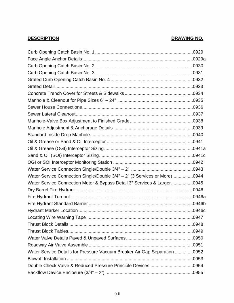
DESCRIPTION DRAWING NO. Curb Opening Catch Basin No. 1 ............................................................................0929 Face Angle Anchor Details......................................................................................0929a Curb Opening Catch Basin No. 2 ............................................................................0930 Curb Opening Catch Basin No. 3 ............................................................................0931 Grated Curb Opening Catch Basin No. 4 ................................................................0932 Grated Detail ...........................................................................................................0933 Concrete Trench Cover for Streets & Sidewalks .....................................................0934 Manhole & Cleanout for Pipe Sizes 6” – 24” ..........................................................0935 Sewer House Connections......................................................................................0936 Sewer Lateral Cleanout...........................................................................................0937 Manhole-Valve Box Adjustment to Finished Grade.................................................0938 Manhole Adjustment & Anchorage Details ..............................................................0939 Standard Inside Drop Manhole................................................................................0940 Oil & Grease or Sand & Oil Interceptor ...................................................................0941 Oil & Grease (OGI) Interceptor Sizing .....................................................................0941a Sand & Oil (SOI) Interceptor Sizing.........................................................................0941c OGI or SOI Interceptor Monitoring Station ..............................................................0942 Water Service Connection Single/Double 3/4” – 2” ................................................0943 Water Service Connection Single/Double 3/4” – 2” (3 Services or More) ...............0944 Water Service Connection Meter & Bypass Detail 3” Services & Larger.................0945 Dry Barrel Fire Hydrant ...........................................................................................0946 Fire Hydrant Turnout ...............................................................................................0946a Fire Hydrant Standard Barrier .................................................................................0946b Hydrant Marker Location .........................................................................................0946c Locating Wire Warning Tape...................................................................................0947 Thrust Block Details ................................................................................................0948 Thrust Block Tables.................................................................................................0949 Water Valve Details Paved & Unpaved Surfaces....................................................0950 Roadway Air Valve Assemble .................................................................................0951 Water Service Details for Pressure Vacuum Breaker Air Gap Separation ..............0952 Blowoff Installation ..................................................................................................0953 Double Check Valve & Reduced Pressure Principle Devices .................................0954 Backflow Device Enclosure (3/4” – 2”) ...................................................................0955
9-ii

9-iii
DESCRIPTION DRAWING NO. Backflow Device Enclosure (3” – 8”) ......................................................................0955a Bacteriological Sample Station Installation..............................................................0956 Bacteriological Sample Station Enclosure...............................................................0957 Utility Locations .......................................................................................................0958 Utility Trench Details (Types A, B & C) ...................................................................0959 Ground Water Monitoring Well ................................................................................0960 Survey Monuments .................................................................................................0961 Flood Gate Fencing.................................................................................................0962 Individual Mailbox Installation..................................................................................0963 Title Block and Border .............................................................................................0964


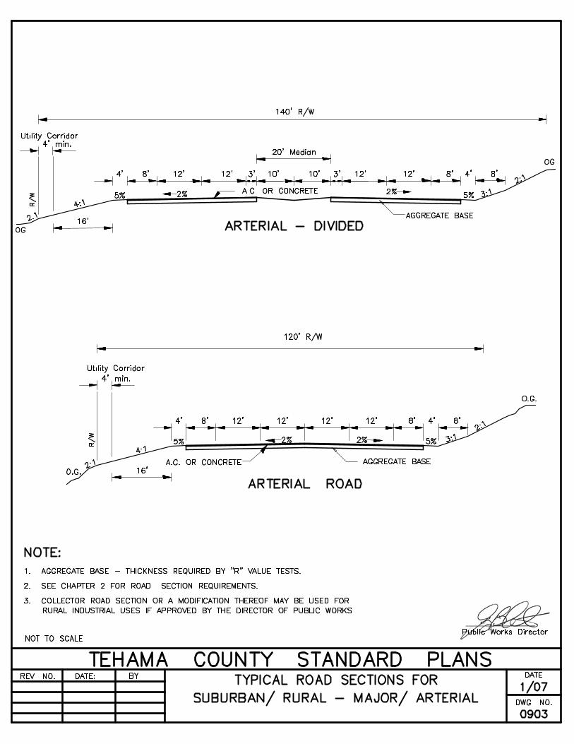


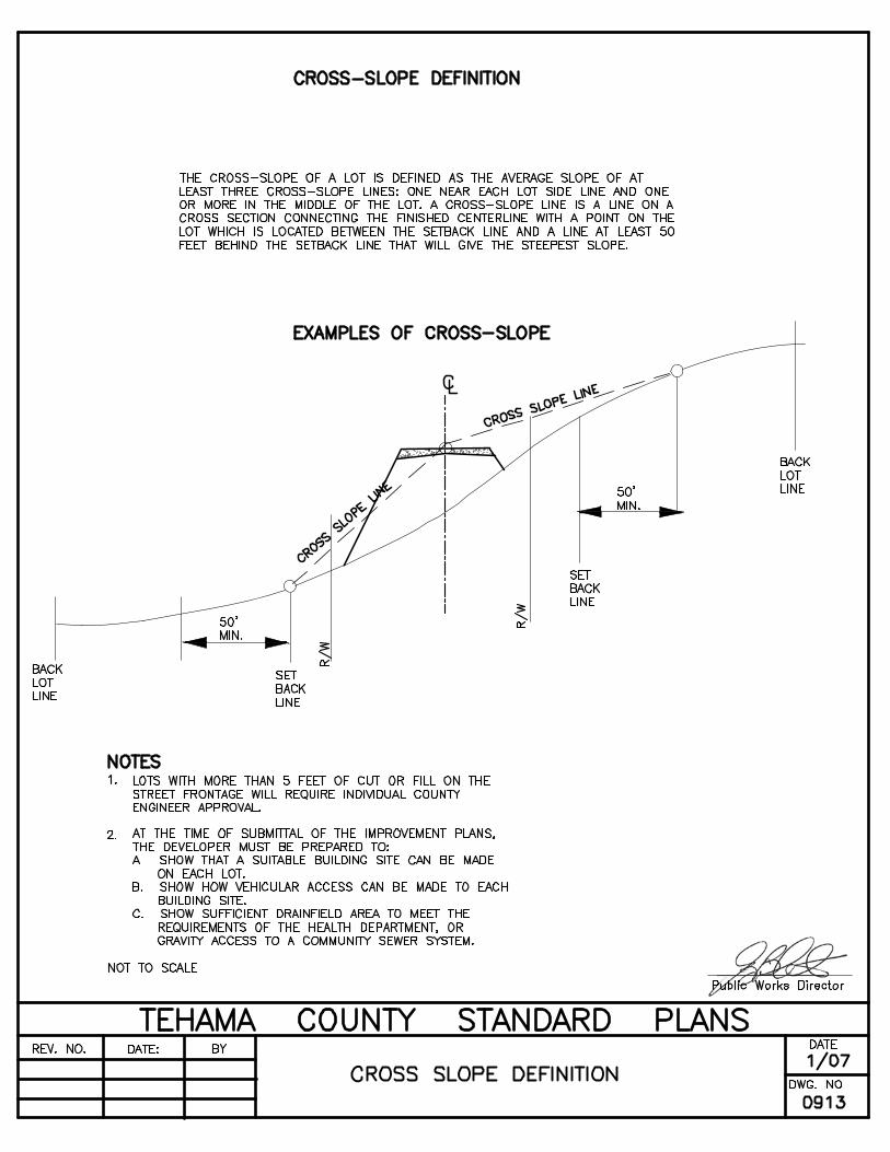
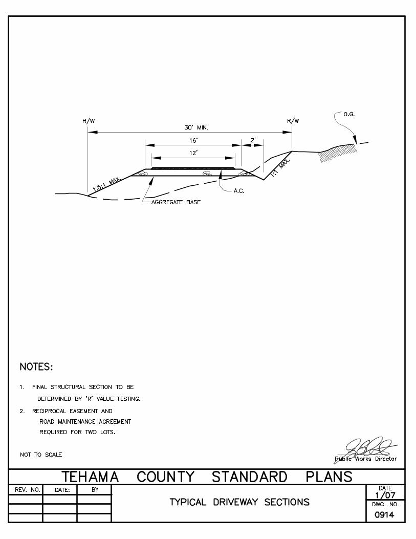
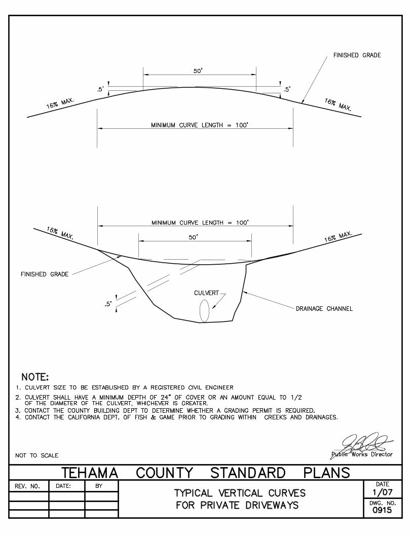


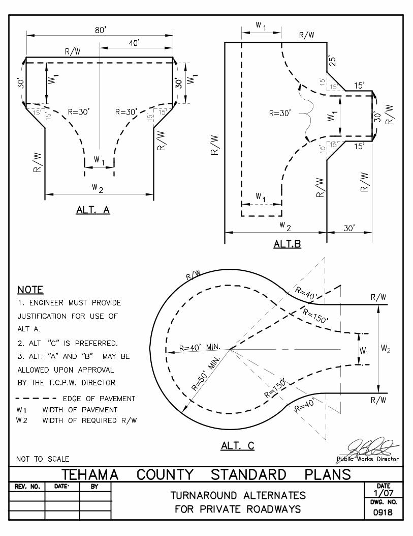
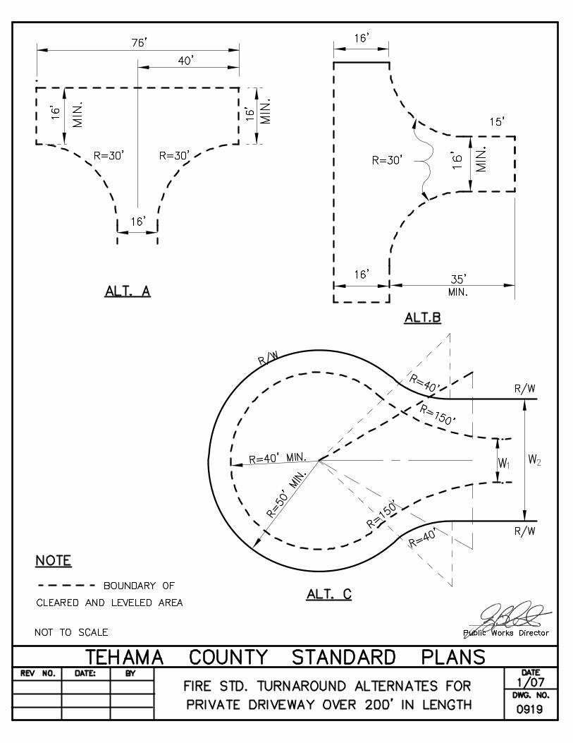

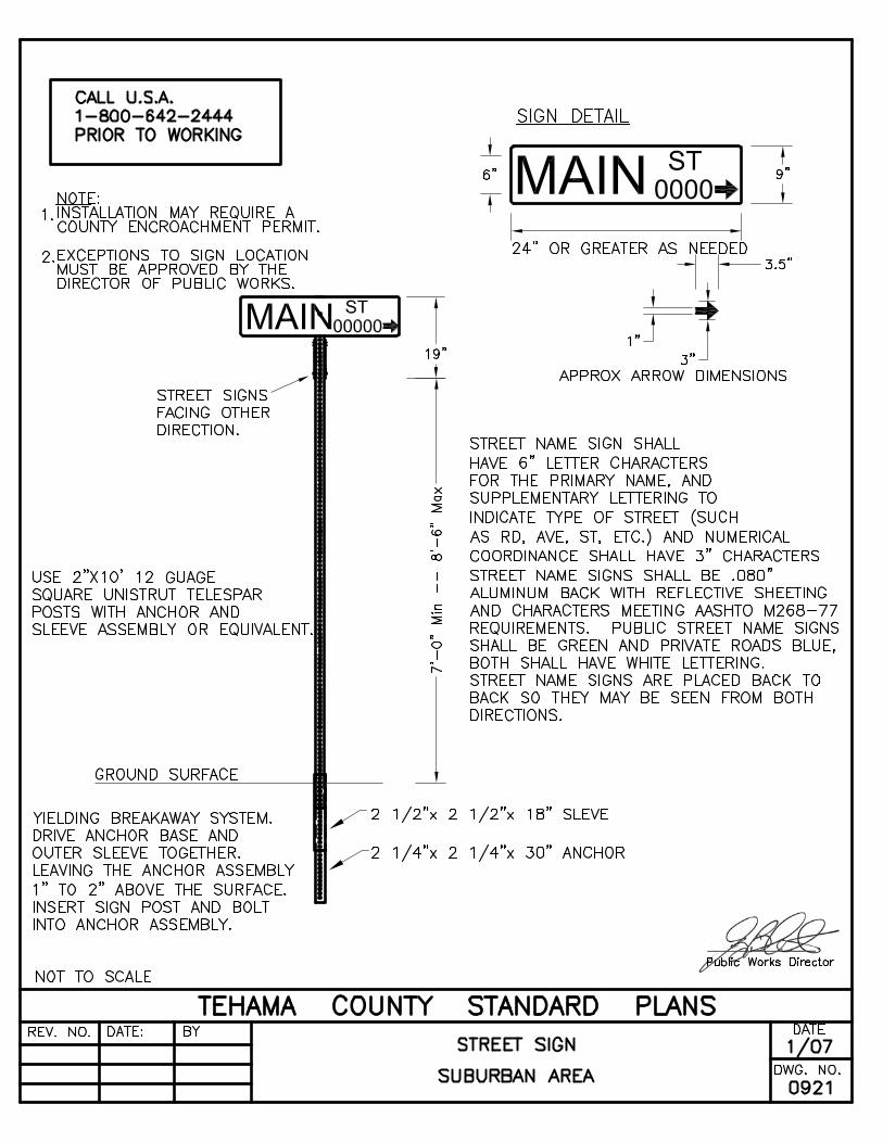


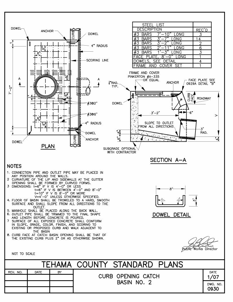


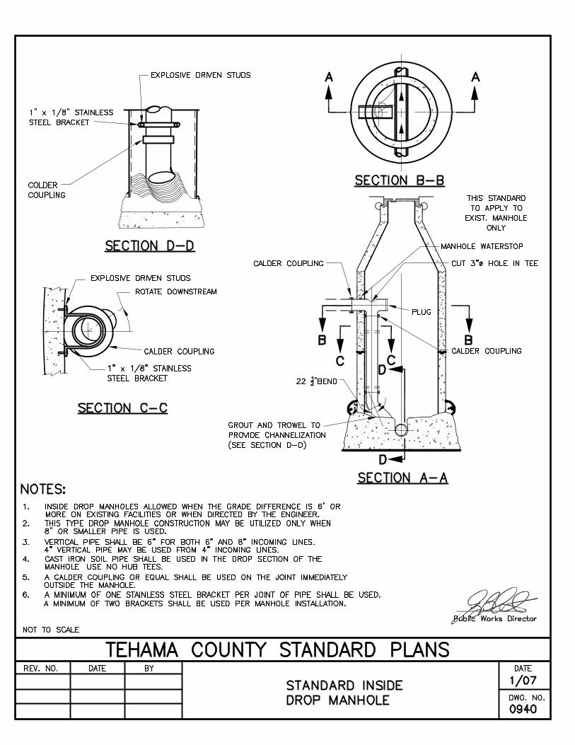


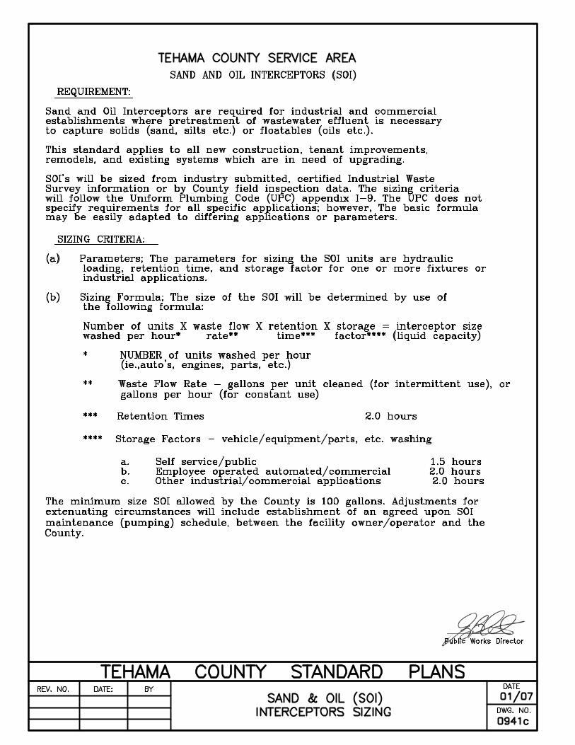

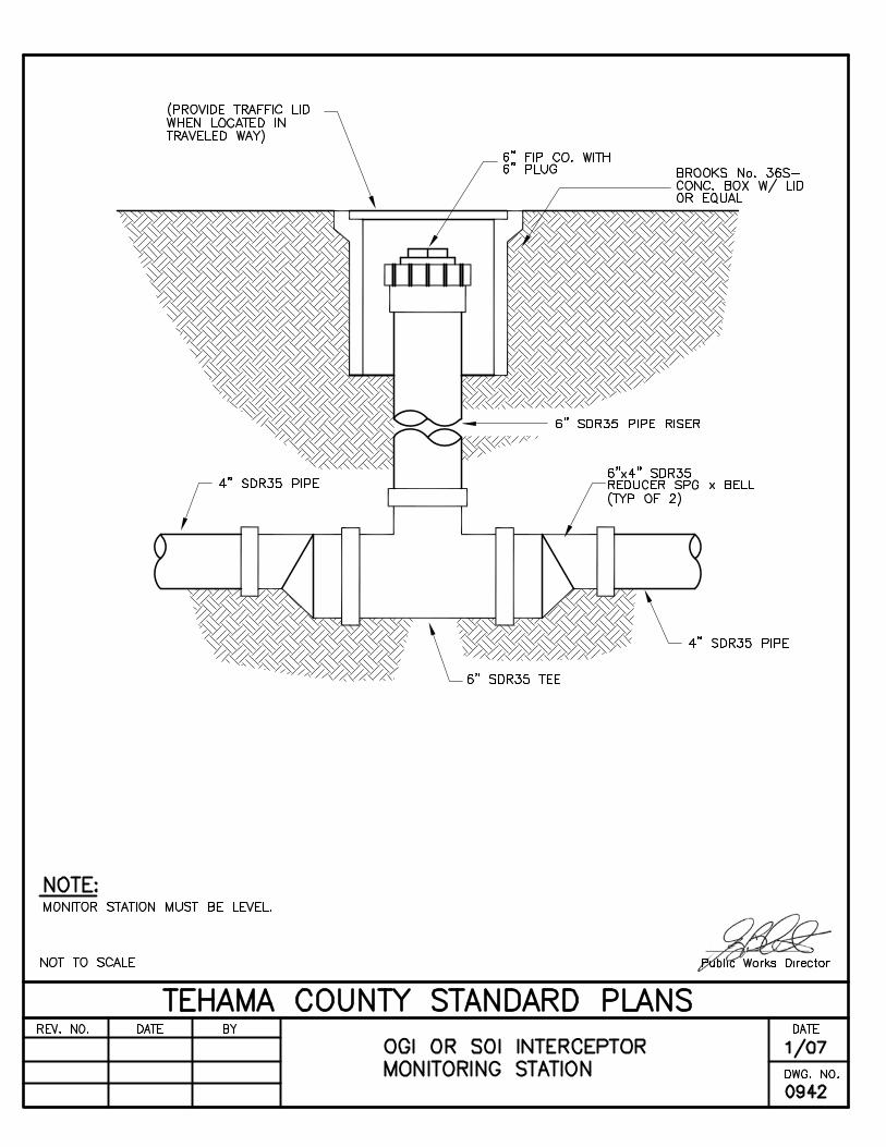
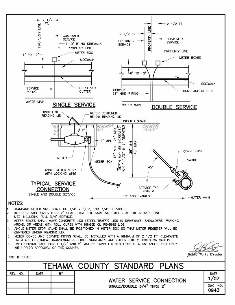


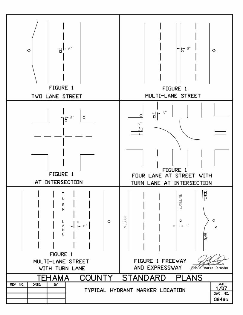


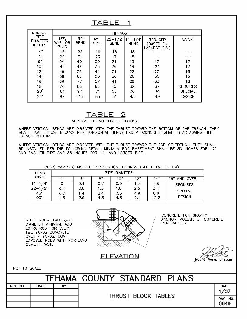


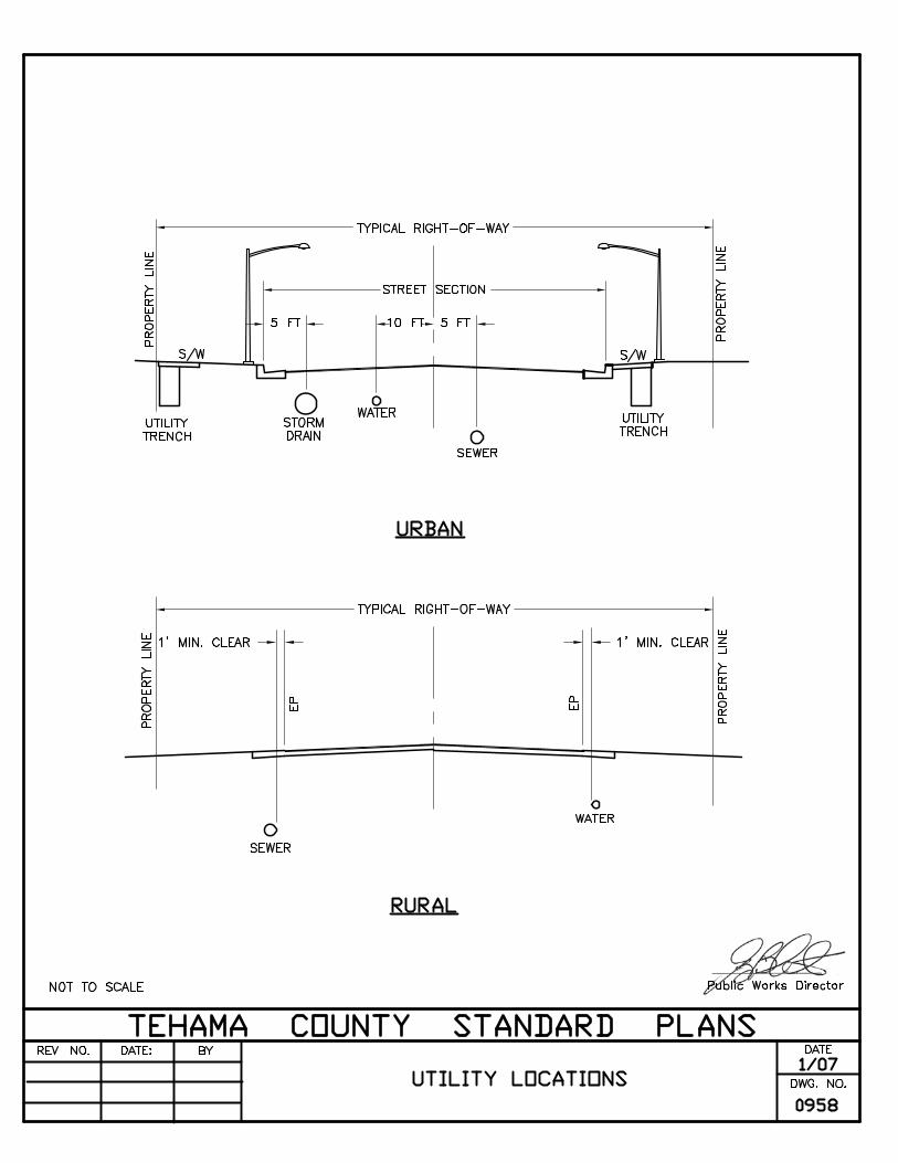


CHAPTER 10
DRAINAGE
DESIGN
TABLES
AND
CHARTS

CHAPTER 10 - DRAINAGE DESIGN TABLES AND CHARTS A. DRAINAGE & HYDROLOGY ANALYSIS DATA This chapter includes the drainage and hydrology analysis data necessary for the design of drainage improvements required by Chapter 2. The basic design criterion is presented in the attached tables, charts, and graphs. The information contained herein is not meant to be all inclusive and other equivalent methods for drainage design that are accepted in the industry may be employed upon the prior approval of the Director of Public Works. B. DRAINAGE DESIGN DIAGRAMS TITLE DRAWING NUMBERS
RATIONAL METHOD
TIME OF CONCENTRATION (L=100-1500) .............................1001
TIME OF CONCENTRATION (L=1000+) ..................................1002
ISOPLUVIAL MAP.....................................................................1003
RAINFALL INTENSITY - 10 YEAR............................................1004
RAINFALL INTENSITY - 25 YEAR............................................1005
RAINFALL INTENSITY - 100 YEAR..........................................1006
HYDROLOGIC SOIL GROUPS.................................................1007
RUNOFF COEFFICIENT CURVE - SOIL CLASS B..................1008
RUNOFF COEFFICIENT CURVE - SOIL CLASS C..................1009
RUNOFF COEFFICIENT CURVE - SOIL CLASS D..................1010
U.S.D.A. NATURAL RESOURCES CONSERVATION SERVICE METHOD
(www.nrcs.usda.gov)
SAMPLE NCRS COMPUTATION SHEET.................................1011
NCRS RUNOFF CURVE NUMBERS ........................................1012
10-1


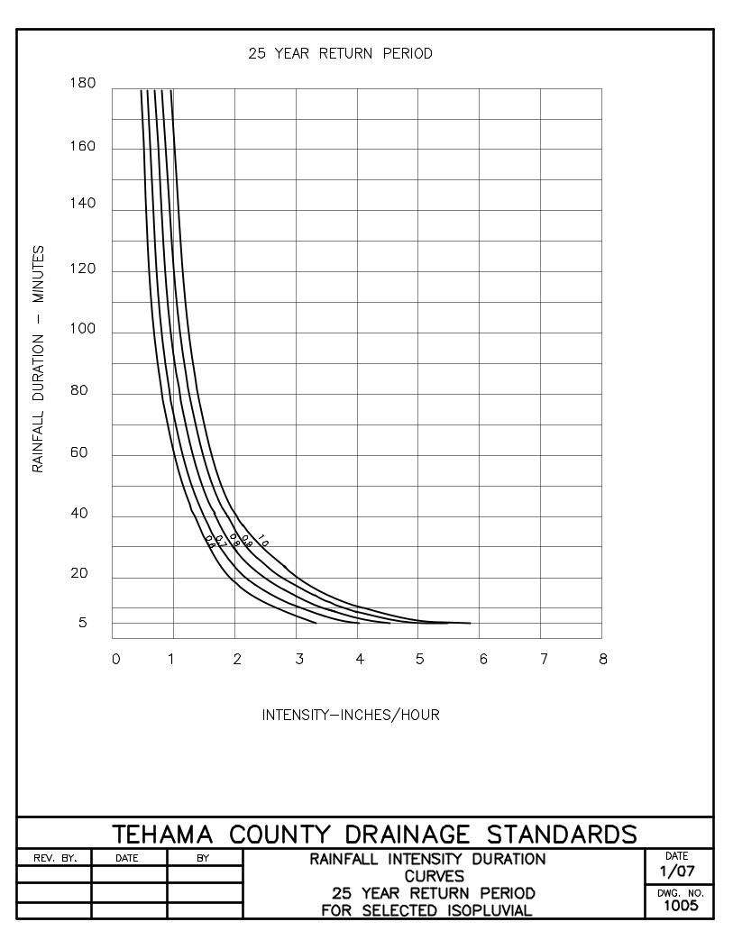


AIKEN ...............................................B LYONSVILLE .......................................C ALTAMONT ...................................... D MANTON .............................................B ANITA ............................................... D MASTERSON ......................................B ARBUCKLE....................................... C MAYWOOD..........................................B BERRENDOS ...................................B MCARTHY ...........................................C CHILDS.............................................B MILLRACE ...........................................B CHUMMY..........................................D MILLSAP..............................................D COHAS .............................................C MILLSSHOM........................................D COLUMBIA .......................................B MODA ..................................................C CONE................................................ A MOLINOS ............................................B CORNING .........................................D MYERS ................................................D CORTINA..........................................A NACIMIENTO.......................................C DIBBLE ............................................. C NANNY ................................................B DUBAKELLA.....................................C NEUNS.................................................D ELAM ................................................A NEWVILLE ...........................................C ELAM, Hard Substratum ................... B ORLAND ..............................................B FARWELL .........................................C PARRISH .............................................D FORWARD........................................C PERKINS .............................................C GOULDING.......................................D PLEASANTON.....................................C GUENOC ..........................................C REDBLUFF ..........................................C HENNEKE.........................................D REDDING.............................................D HILLGATE.........................................C SEHORN..............................................D HUGO ...............................................C SHEETIRON ........................................D HULLS...............................................C STONYFORD.......................................D INKS..................................................D SUPAN.................................................D INSKIP ..............................................C TEHAMA ..............................................C IRONMOUNTAIN ..............................D TOOMES..............................................D JIGGS ...............................................D TUSCAN ..............................................D JOSEPHINE...................................... C TYSON.................................................B KEEFERS ......................................... C VINA.....................................................B KIMBALL...........................................B WINDY .................................................C LANIGER ..........................................C WYO ....................................................C LODO................................................D YOLLABOLLY ......................................D LOSGATOS ......................................D YOLO ...................................................B LOSROBLES .................................... C ZAMORA..............................................B
TEHAMA COUNTY STANDARD PLANS REV.NO. DATE BY
DATE 1/07
HYDROLOGIC SOIL GROUPS DWG. NO. 1007


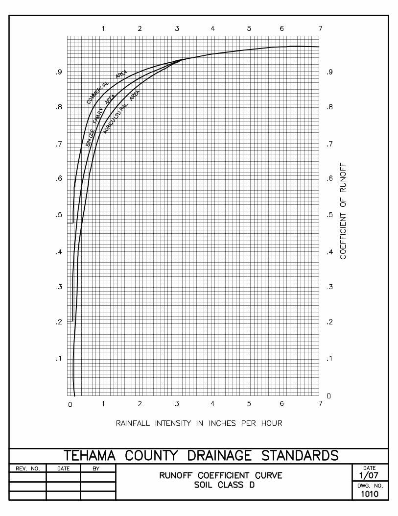

Hydrology Computation, EFH-2 U. S. DEPARTMENT OF AGRICULTURECaArea1-ENG-400 (01/07) NATURAL RESOURCES CONS. SERVICE
Sht: 1
Project: Tributary to Sacramento River Date: 1/7/2007 Filename: Corning High Ranch Computed by: TDB
Quad. Map: Checked by:____________ Soil Survey: Tehama
DRAINAGE AREA (DA): 100.0 acres
RUNOFF CURVE NUMBER (CN)._________ ______________ ______________ ______________ _______________ ______________
HSG Landuse/Condition CN Area CN X Area_________ ______________ ______________ ______________ _______________ ______________
C Range and Oaks 75 100.0 7,500.0
_________ ______________ ______________ ______________ _______________ ______________Weighted CN= 75.0 100.0 7,500.0
Use CN: 75.0
TIME OF CONCENTRATION (Tc).
Flow Length (ft): 3,000 AMC (I,II,or III): II Watershed Slope (%): 10.0 Avg. Velocity (fps)= 1.78 Ponded Area (%): 0.0 Time of Conc. (hr)= 0.47
Use Tc (hr): 0.47
DESIGN PRECIPITATION (P), DESIGN RUNOFF (RO), & DISTRIBUTION TYPE._________ ______________ ______________ ______________ _______________ ______________
Freq. P6 P24 P6/P24 Distrib. RO (yrs) (in) (in) (in/in) Type (in)
_________ ______________ ______________ ______________ _______________ ______________2 1.40 2.50 0.560 I 0.655 1.60 3.00 0.533 I 0.96
10 1.80 3.30 0.545 I 1.1625 2.00 4.00 0.500 IA 1.6750 2.25 4.20 0.536 I 1.82
100 2.40 5.00 0.480 IA 2.45_________ ______________ ______________ ______________ _______________ ______________
Use Type: IA
DESIGN PEAK YIELD (Y) AND DISCHARGE (q)._________ ______________ ______________ ______________ _______________ ______________
Freq. Prob. qu Y qi qo (yrs) (%/yr) (cfs/ac-in) (cfs/ac) (cfs) (cfs)
_________ ______________ ______________ ______________ _______________ ______________2 50 0.119 0.077 7.7 7.75 20 0.145 0.140 14.0 14.0
10 10 0.156 0.182 18.2 18.225 4 0.174 0.290 29.0 29.050 2 0.178 0.324 32.4 32.4
100 1 0.190 0.466 46.6 46.6_________ ______________ ______________ ______________ _______________ ______________
Detention Storage (ac-ft): 0.0

Table 2-2a Runoff curve numbers for urban areas 1/
------------------------------------Cover description --------------------------------------------- Curve numbers for hydrologic soil group -
Cover type and hydrologic condition Average percent impervious area 2/ A B C D
Fully developed urban areas (vegetation established)
Open space (lawns, parks, golf courses, cemeteries, etc.) 3/: Poor condition (grass cover < 50%) ................................ 68 79 86 89 Fair condition (grass cover 50% to 75%)........................ 49 69 79 84 Good condition (grass cover > 75%)....................... ........ 39 61 74 80 Impervious areas: Paved parking lots, roofs, driveways, etc. (excluding right-of-way) ................................................. 98 98 98 98 Streets and roads: Paved; curbs and storm sewers (excluding
right-of-way) ................................................................... 98 98 98 98 Paved; open ditches (including right-of-way)........... ..... 83 89 92 93 Gravel (including right-of-way) ..................................... 76 85 89 91 Dirt (including right-of-way) .................................... ..... 72 82 87 89 Western desert urban areas: Natural desert landscaping (pervious areas only) 4/ .... 63 77 85 88 Artificial desert landscaping (impervious weed barrier,
desert shrub with 1- to 2-inch sand or gravel mulch and basin borders)..................................................... ..... 96 96 96 96
Urban districts: Commercial and business .............................................85 89 92 94 95 Industrial .......................................................................72 81 88 91 93 Residential districts by average lot size: 1/8 acre or less (town houses).........................................65 77 85 90 92 1/4 acre............................................................................38 61 75 83 87 1/3 acre............................................................................30 57 72 81 86 1/2 acre............................................................................25 54 70 80 85 1 acre...............................................................................20 51 68 79 84 2 acres .............................................................................12 46 65 77 82 Developing urban areas Newly graded areas (pervious areas only, no vegetation) 5/ ................................................................ 77 86 91 94 Idle lands (CN’s are determined using cover types similar to those in table 2-2c).
1 Average runoff condition, and Ia = 0.2S. 2 The average percent impervious area shown was used to develop the composite CN’s. Other assumptions are as follows: impervious
areas are directly connected to the drainage system, impervious areas have a CN of 98, and pervious areas are considered equivalent to open space in good hydrologic condition. CN’s for other combinations of conditions may be computed using figure 2-3 or 2-4.
3 CN’s shown are equivalent to those of pasture. Composite CN’s may be computed for other combinations of open space cover type.
4 Composite CN’s for natural desert landscaping should be computed using figures 2-3 or 2-4 based on the impervious area percentage (CN = 98) and the pervious area CN. The pervious area CN’s are assumed equivalent to desert shrub in poor hydrologic condition.
5 Composite CN’s to use for the design of temporary measures during grading and construction should be computed using figure 2-3 or 2-4 based on the degree of development (impervious area percentage) and the CN’s for the newly graded pervious areas.

i
GLOSSARY
OF
TERMS

GLOSSARY OF TERMS
i
AADTT ........................................................................ Annual Average Daily Traffic Total
AASHTO ................ American Association of State Highway and Transportation Officials
ADT.................................................................................................. Average Daily Traffic
ANSI...................................................................... American National Standards Institute
APN......................................................................................... Assessor’s Parcel Number
ASTM ................................................................... American Society for Testing Materials
AWWA....................................................................... American Water Works Association
BC ..................................................................................................................Begin Curve
BLM...............................................................United States Bureau of Land Management
BMP ....................................................................................... Best Management Practice
BVC...................................................................................................Begin Vertical Curve
CBC.............................................................................................California Building Code
CC&R..................................................................... Conditions, Covenants & Restrictions
CDF............................................................California Department of Forestry (CALFIRE)
CEQA....................................................................... California Environmental Quality Act
C.L. or ..........................................................................................................Centerline CLCMP .............................................................................................. Corrugated Metal Pipe
DBH.......................................................................................... Diameter at Breast Height
EC .................................................................................................................... End Curve
EVC..................................................................................................... End Vertical Curve
HEC-HMS ........................ Hydrological Engineering Center-Hydrology Modeling System
LS ..............................................................................................................Land Surveyor
MGD..............................................................................................Million Gallons per Day
MPI......................................................................................................... Minutes Per Inch
MUTCD ..........................................................Manual on Uniform Traffic Control Devices
NEPA ...........................................................................National Environmental Policy Act
NFPA.........................................................................National Fire Protection Association
NST.......................................................................................... National Standard Thread
OR..............................................................................................................Official Record
OSHA.................................................................Occupational Safety Hazard Association

GLOSSARY OF TERMS
ii
PE .................................................................................................. Professional Engineer
PLS ....................................................................................... Professional Land Surveyor
PM................................................................................................................... Parcel Map
PRD...........................................................................................Permanent Road Division
PSIG................................................................................Pounds per Square Inch Gauge
R/S .........................................................................................................Record of Survey
R/W or ROW ................................................................................................ Right-of-Way
RCE...........................................................................................Registered Civil Engineer
RFDA ............................................................... Repair of Failure and Defects Agreement
RMA ..................................................................................Road Maintenance Agreement
SCS.......................................................................................... Soil Conservation Service
SRA........................................................................................... State Responsibility Area
USC & GS ....................................................... United States Coastal & Geodetic Society
USGS.............................................................................United States Geological Survey