Embed Size (px)
Citation preview
LAND & MARINE WESTMINSTER JV
01 February 2010 For information and approval LMW JV
Status Date Description Originator Reviewed QA Approved
Client: 4DELIVERY LTD
Project: BRIGHTON & HOVE WASTEWATER TREATMENT SCHEME
FRIARS’ BAY OUTFALL
Client Project No: 44985
Document Title: PROJECT EXECUTION PLAN
FOR THE INSTALLATION OF
THE LONG SEA OUTFALL
Document No: 20385–PRO–PENG–009
Contractor
LMW JV
Project
Brighton & Hove WWTS Friars’ Bay Long Sea Outfall
Document No.
20385–PRO–PENG-009
Document Title PROJECT EXECUTION PLAN
Date: 05/01/10 Rev: 01 Page 2 of 18
CONTENTS
1.0 INTRODUCTION 2.0 SCOPE
2.1 General 2.2 Documents
3.0 SITE PREPARATION FOR ASSEMBLY OF LONG SEA OUTFALL 4.0 PIPE STRING DELIVERY AND PULL ASHORE 5.0 CONCRETE SLEEVE WEIGHT ATTACHMENT 6.0 DIFFUSER STRING PREPARATION 7.0 PIPE STRING PRE LAUNCH PREPARATION 8.0 MARINE BASED OPERATIONS
8.1 Mobilisation for Dredging Operations 8.2 Trench Dredging by Backhoe Dredger
9.0 LAUNCHING OPERATIONS 10.0 INSTALLATION OF THE OUTFALL PIPELINE AND DIFFUSERS 11.0 BACKFILLING 12.0 COMPLETION OF THE DIFFUSERS 13.0 COMPLETION OF THE TUNNEL TO OUTFALL PIPELINE
13.1 TBM Recovery 13.2 Spoolpiece Installation
14.0 REINSTATEMENT APPENDICES A Pipe String Delivery And Installation Sequence Schematic ADD TESTING PROPOSALS?????????????????????? JOINT TEST DURING LAUNCH DIFFUSER TYEST
Contractor
LMW JV
Project
Brighton & Hove WWTS Friars’ Bay Long Sea Outfall
Document No.
20385–PRO–PENG-009
Document Title PROJECT EXECUTION PLAN
Date: 05/01/10 Rev: 01 Page 3 of 18
1.0 INTRODUCTION
Southern Water’s environmental improvement scheme to bring cleaner seas to East Sussex includes 11km of sewer between Brighton Marina and Peacehaven, a wastewater treatment works and sludge treatment centre at Lower Hoddern Farm, Peacehaven. After treatment, the cleaned wastewater will be released approximately 2.5km offshore through a new long sea outfall (LSO) at Friars’ Bay.
4D has awarded a contract to Land & Marine Westminster Joint Venture (comprising Land & Marine Project Engineering Ltd and Westminster Dredging Co. Ltd.) for the construction, assembly and installation of the offshore section of the Long Sea Outfall (LSO).
Land & Marine Project Engineering (L&M) will carry out the onshore preparation and installation of the LSO; Westminster Dredging Co. Ltd. (WDC) will undertake all associated marine surveys, trench dredging and backfilling activities.
As L&M and WDC operate management systems which comply with ISO 9001 (2000), then both parties will operate within their own Corporate Quality, Safety and Environmental Management Systems to develop their own project plans for the execution of their respective scopes of work within the LMW JV.
This Project Execution Plan is intended to provide an overview of the methods to be employed in the installation of the Long Sea Outfall.
2.0 SCOPE OF WORK
2.1 General
The Friars’ Bay LSO comprises an 1850m long pipe including diffuser section installed in a dredged trench. The LSO will be installed with a nominal depth of cover of between 1.5 and 2.0m in up to 20m of water.
The offshore section of the LSO comprises 1400mm OD SDR 26 high performance polyethylene (HPPE) pipe assembled in three lengths (or strings) of approximately 553m with a 200m long tapered diffuser section.
The LSO pipe strings and diffuser section will be towed by sea from the manufacturer’s (Pipelife International GmbH) factory in Norway to an agreed location off Newhaven where the JV will take possession of the pipes.
The outfall pipeline will be recovered onshore and assembled and fitted with additional weight in the form of precast concrete weight-collars (CWCs). The JV proposes to assemble the outfall and fit the CWCs to the pipe strings close to Newhaven.
The outfall pipeline will assembled into one complete length and towed to the installation site where the pipeline will be positioned into the pre-dredged trench by the float / flood method.
The diffuser trench will be backfilled with selected material to enable the installation of the diffuser risers and protective domes. Scour protection will then be placed to complete the backfill to the diffuser section.
A support vessel will mobilise to the TBM recovery pit and divers will remove the material from around the TBM which will then be recovered and taken to the port. Having removed the TBM
Contractor
LMW JV
Project
Brighton & Hove WWTS Friars’ Bay Long Sea Outfall
Document No.
20385–PRO–PENG-009
Document Title PROJECT EXECUTION PLAN
Date: 05/01/10 Rev: 01 Page 4 of 18
the outfall pipe will be connected to the tunnel by means of a spoolpiece. The spoolpiece trench will be backfilled.
The main trench will be backfilled using the pre-excavated material.
The installation of a marker buoy placed at the end of the diffuser trench will complete the installation work.
The management and installation of the outfall pipeline will be carried out in accordance with the outline details described herein; specific project documentation will be developed and issued to 4D for their information / approval.
A preliminary list of procedures is included for reference in section 2.2; the list will be developed and form part of the document register for the project.
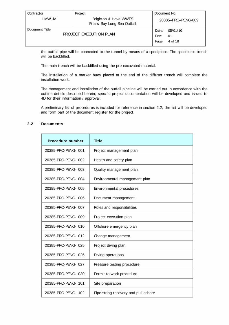
2.2 Documents
Procedure number Title
20385-PRO-PENG- 001 Project management plan
20385-PRO-PENG- 002 Health and safety plan
20385-PRO-PENG- 003 Quality management plan
20385-PRO-PENG- 004 Environmental management plan
20385-PRO-PENG- 005 Environmental procedures
20385-PRO-PENG- 006 Document management
20385-PRO-PENG- 007 Roles and responsibilities
20385-PRO-PENG- 009 Project execution plan
20385-PRO-PENG- 010 Offshore emergency plan
20385-PRO-PENG- 012 Change management
20385-PRO-PENG- 025 Project diving plan
20385-PRO-PENG- 026 Diving operations
20385-PRO-PENG- 027 Pressure testing procedure
20385-PRO-PENG- 030 Permit to work procedure
20385-PRO-PENG- 101 Site preparation
20385-PRO-PENG- 102 Pipe string recovery and pull ashore

Contractor
LMW JV
Project
Brighton & Hove WWTS Friars’ Bay Long Sea Outfall
Document No.
20385–PRO–PENG-009
Document Title PROJECT EXECUTION PLAN
Date: 05/01/10 Rev: 01 Page 5 of 18
Procedure number Title
20385-PRO-PENG- 103 Onshore outfall pipe preparation
20385-PRO-PENG- 104 Onshore diffuser test procedure
20385-PRO-PENG- 105 Pipe string launch and outfall pipeline installation
20385-PRO-PENG- 106 Riser and protection dome installation
20385-PRO-PENG- 107 TBM recovery and spool piece installation
20385-PRO-PENG- 108 Traffic management plan
20385-PRO-PENG- 109 Noise management plan
20385-PRO-PENG- 110 Onshore emergency procedure
20385-PRO-PENG- 111 SLP Inspection Plan for 1400 dia Sleeve Weights
20385-PRO-PENG- 112 Pipelife Report on 1400 Pipe
Drawing number Title
20385-DRG-DENG-001 Concrete Sleeve Weight
20385-DRG-DENG-003 Proposed temporary pipe string assembly site and launch profile
20385-DRG-DENG-013 Insert Connector
20385-DRG-DENG-014 Flanged Connector
20385-DRG-DENG-015 GA of Tunnel to Outfall Spoolpiece
20385-DRG-DENG-0xx Float Flood Installation Sequence
20385-DRG-DENG-017 Launch Schematics
20385-DRG-DENG-019 Diffuser Dome Installation Sequence

Contractor
LMW JV
Project
Brighton & Hove WWTS Friars’ Bay Long Sea Outfall
Document No.
20385–PRO–PENG-009
Document Title PROJECT EXECUTION PLAN
Date: 05/01/10 Rev: 01 Page 6 of 18
3.0 SITE PREPARATION FOR ASSEMBLY OF LONG SEA OUTFALL
The JV proposes to use an area of land owned by Newhaven Port and Properties Ltd (NPP) bounded by the port and the River Ouse to the West and Mill Creek and Tide Mills to the North and East for the assembly of the outfall pipe strings, Figure 1.0 refers.
Fig 1.0: Site Location
The JV will undertake a pre-construction survey and make a photographic record of the site and environs. The pre-construction survey will include the identification and location, protection and marking of services on the site.
Any requirements of the authorities for the permissions to access and use the site will be complied with in full.
Topsoil will be stripped over the working width and stored adjacent to the area from which it was removed.
A temporary access road will be constructed using sub-base type stone material over a geotechnical membrane from the NPP gates to the construction site area to allow for the safe movement of vehicles and plant. Haul and access roads will be constructed along both sides of the pipe string storage area, Drawing 20385-DRG-DENG-003 refers.
Hard-standings will be prepared in the same way as the site access road for the site office, welfare facilities, vehicle parking areas and for the storage of precast concrete weights.
Electric power, lighting, water supply, drainage, communications, fuel and oil storage etc will be provided and maintained.
Contractor
LMW JV
Project
Brighton & Hove WWTS Friars’ Bay Long Sea Outfall
Document No.
20385–PRO–PENG-009
Document Title PROJECT EXECUTION PLAN
Date: 05/01/10 Rev: 01 Page 7 of 18
Appropriate fencing will be erected around the site as necessary.
To enable the assembly and launch of the strings temporary construction plinths and a railtrack will be set up; the railtrack will be recessed below the general ground level and the plinths will be set up perpendicularly to the railtrack alignment. The plinths may comprise profiled berms and temporary timbers.
For the pull offshore of the strings conveyor rollers will be positioned on temporary supports across the shingle beach between the end of the railtrack on the site area and the waterline and on the same alignment as the railtrack.
4.0 PIPE STRING DELIVERY AND PULL ASHORE
The Maritime and Coastguard Agency, Defra the Crown Estate and other stakeholders as appropriate will be contacted and advised of the works and appropriate notices will be issued to warn of the operations at sea.
The proposed pipe string delivery and installation sequence is given in Appendix A.
The four pipe strings ( 3No. x 553m long and 1No. diffuser section x 200m long ) will be surface towed from Norway and delivered to an agreed point offshore Newhaven and handed over to the JV. When the JV has accepted the pipe strings they will secured to a JV vessel or a suitable temporary mooring until they can be taken ashore.
Guard vessels and beacons will be used as necessary to ensure the safety of and to maintain control of the pipe strings.
Recovery wires will be positioned between excavators positioned above the High Water Mark (HWM) and an inshore location within the bay. A string will be separated from the others and towed to the beach area where the lead end will be connected to the recovery wire.
Onshore excavators will then commence the pull ashore of the pipe string up the beach using the recovery wire. Additional excavators will be used as the pipe string is recovered. The excavators will continue the pull ashore operation so that the pipe string can be placed on bogies located on the railtrack.
The remaining strings will be recovered in a similar manner and placed on the temporary plinths/berms and stored parallel to the launch line.
5.0 CONCRETE SLEEVE WEIGHT ATTACHMENT
Concrete Sleeve Weights (CSW) will be delivered to site by articulated lorries via NPP’s main entrance and will be stored on storage areas constructed within the site.
No special vehicles are anticipated and it is expected that up to 150 lorry movements will be required to deliver all the precast concrete elements. Deliveries will be in accordance with an agreed schedule with the precast supplier, Sea and Land Precast, and NPP will be notified of all major vehicle movements.
It is envisaged that the diffuser domes will be offloaded within the port for later load out onto a vessel.
Contractor
LMW JV
Project
Brighton & Hove WWTS Friars’ Bay Long Sea Outfall
Document No.
20385–PRO–PENG-009
Document Title PROJECT EXECUTION PLAN
Date: 05/01/10 Rev: 01 Page 8 of 18
The CSWs will be picked up from the storage areas and carried by excavator to the ends of the pipe string being worked on and threaded over the pipe string. The excavator will then track alongside the pipe string until the CSW is in the correct position where it will be released. The excavator will repeat the process until all the CSWs are in position.
Drawing No. 20385-DRG-DENG-001 shows a typical sleeve weight.
Each sleeve weight will be fitted with rubber or polyurethane, or similar, buffers at the 3 and 9 o’clock positions to ensure flexibity of the pipe string during installation.
Circumferential locking clamps will be fitted between a set number of sleeve weights to ensure that the sleeve weights provide an even weight distribution along the outfall pipeline to meet the required 1.42SG.
It is expected that a number of excavator spreads will be required to accomplish sleeve weight attachment in a timely manner.
Prior to the application of the sleeve weights a nominal 30m length will be cut off from one of the strings to use as part of the spoolpiece for the tunnel-to-outfall pipeline completion work.
6.0 DIFFUSER STRING PREPARATION
It is planned that the 200m long diffuser section will be installed with the 3 main pipe strings (2No. x 553m long and 1No. x 523m long) strings during the float/flood operation.
To accomplish this the diffuser section will also be fitted with cylindrical sleeve weights. The sleeve weights will be threaded over the diffuser section and gaps will be provided between the weights to enable the attachment of the riser stubs by Pipelife.
Once the 12No. Riser Feet, complete with flanged stub ends, have been attached, sacrificial straps will be clamped around the shoulders of each fitting. Steel fabrications will be fitted to each taper section of the diffuser and to each riser to provide support.
The 1400mm dia. end of the diffuser will be fitted with an Insert Connector ( for details of the Insert Connector Drawing No 2.385-DRG-DENG-013 refers ) and a blind flange; the 450mm dia. end of the diffuser, Riser No.12, will be fitted with the long radius bend closed off with a blind flange.
The diffuser section will then be tested with air to a pressure of 1bar for 10mins to prove the integrity of the fittings / connections.
Sections of sleeve weights will be restrained together to ensure that the sleeve weights remain in position and provide an even weight distribution along the diffuser section. Sacrifical steel clamps will also be used as appropriate.
One of the blank flanges to the risers will be fitted with a flooding hose, engineering will determine which riser will be used.
7.0 PIPE STRING PRE LAUNCH PREPARATION
On completion of sleeve weight attachment to the strings the inshore ends of the strings will be fitted with an Insert Connector. The connector comprises a tubular steel snug fit insert locked in position by external bolted clamps.

Contractor
LMW JV
Project
Brighton & Hove WWTS Friars’ Bay Long Sea Outfall
Document No.
20385–PRO–PENG-009
Document Title PROJECT EXECUTION PLAN
Date: 05/01/10 Rev: 01 Page 9 of 18
Shoulda a leak test of the connectors be required then this would be undertaken at this stage.
The seaward end of the pipe string on the railtrack, (which will eventually connect to the tunnel by means of a spoolpiece) will be fitted with a tow point on a blank flange clamped to a Flange Connector.
A bogie recovery pit will be formed at the end of the railtrack to enable the bogies to be recovered and the first conveyor roller to support the pipe.
The launch spread will mobilise to the bay and a tow wire will be installed between the beach and the launch vessel; this may be a barge or a tug.
8.0 MARINE BASED OPERATIONS
8.1 Mobilisation for Dredging Operations
The intention for mobilisation is to co-ordinate the commencement of site set-up, and pre-survey work such that the dredging works may be completed to coincide with the timing for pipe installation work.
Mobilisation will entail the following:-
• Establishment and installation of survey equipment.
• Mobilisation of crew / survey vessel from its home port. The survey and positioning equipment will be installed, checked and calibrated. Installation may take place either at the home port or upon arrival on site.
• Mobilisation of the backhoe dredger ‘Nordic Giant’ from the location of its previous project. The dredger must be prepared in advance, which includes sea fastening of all equipment and securing the spud legs in position. A large sea-going tug will tow the backhoe directly to site.
Upon arrival on site, the dredger will release all sea fastenings from all equipment and spud legs, which may be performed without access to the quay side assistance, weather permitting. During this time, the positioning system will be updated and checked in line with the Survey Procedures.
8.2 Trench Dredging by Backhoe Dredger
Prior to the works commencing a hydrographic survey will be undertaken of the work area to determine the pre dredge seabed levels.
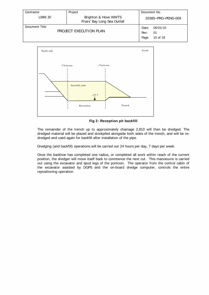
Work will commence at chainage 950 (Drawing WE-POOF-011/INF/0021 Rev. 2) by dredging the reception pit, continued by normal trench dredging. Once the dredging has advanced sufficiently, the reception pit will be partly backfilled as shown on drawing 44985.02002 Rev. A, with sand from the surrounding seabed. It is anticipated that a slope on the North side of the reception pit will be formed. The south side of the reception pit will be dredged and the backfill material will be placed over a length of 13 m (chainage 950 – 963) from where it will slope down to the bottom of the trench (see Figure 2 below).
Contractor
LMW JV
Project
Brighton & Hove WWTS Friars’ Bay Long Sea Outfall
Document No.
20385–PRO–PENG-009
Document Title PROJECT EXECUTION PLAN
Date: 05/01/10 Rev: 01 Page 10 of 18
TrenchReception
SouthNorth side
Backfill with
-15 2
ChainageChainage
Fig 2: Reception pit backfill
The remainder of the trench up to approximately chainage 2,810 will then be dredged. The dredged material will be placed and stockpiled alongside both sides of the trench, and will be re-dredged and used again for backfill after installation of the pipe.
Dredging (and backfill) operations will be carried out 24 hours per day, 7 days per week.
Once the backhoe has completed one radius, or completed all work within reach of the current position, the dredger will move itself back to commence the next cut. This manoeuvre is carried out using the excavator and spud legs of the pontoon. The operator from the control cabin of the excavator assisted by DGPS and the on-board dredge computer, controls the entire repositioning operation.
Contractor
LMW JV
Project
Brighton & Hove WWTS Friars’ Bay Long Sea Outfall
Document No.
20385–PRO–PENG-009
Document Title PROJECT EXECUTION PLAN
Date: 05/01/10 Rev: 01 Page 11 of 18
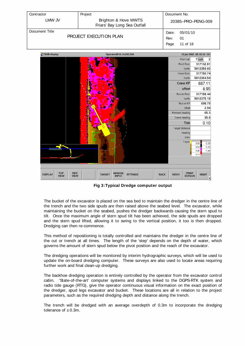
Fig 3:Typical Dredge computer output
The bucket of the excavator is placed on the sea bed to maintain the dredger in the centre line of the trench and the two side spuds are then raised above the seabed level. The excavator, while maintaining the bucket on the seabed, pushes the dredger backwards causing the stern spud to tilt. Once the maximum angle of stern spud tilt has been achieved, the side spuds are dropped and the stern spud lifted, allowing it to swing to the vertical position, it too is then dropped. Dredging can then re-commence.
This method of repositioning is totally controlled and maintains the dredger in the centre line of the cut or trench at all times. The length of the ‘step’ depends on the depth of water, which governs the amount of stern spud below the pivot position and the reach of the excavator.
The dredging operations will be monitored by interim hydrographic surveys, which will be used to update the on-board dredging computer. These surveys are also used to locate areas requiring further work and final clean-up dredging.
The backhoe dredging operation is entirely controlled by the operator from the excavator control cabin. ‘State-of-the-art’ computer systems and displays linked to the DGPS-RTK system and radio tide gauge (RTG), give the operator continuous visual information on the exact position of the dredger, spud legs excavator and bucket. These locations are all in relation to the project parameters, such as the required dredging depth and distance along the trench.
The trench will be dredged with an average overdepth of 0.3m to incorporate the dredging tolerance of ±0.3m.
Contractor
LMW JV
Project
Brighton & Hove WWTS Friars’ Bay Long Sea Outfall
Document No.
20385–PRO–PENG-009
Document Title PROJECT EXECUTION PLAN
Date: 05/01/10 Rev: 01 Page 12 of 18
The on-board dredge / positioning system allows continuous monitoring and recording of all the information in real time from the on-board supervisors office.
On completion of trench dredging, a Post-Dredge / Pre-Lay survey will be undertaken and upon acceptance that the trench is ready, pipe installation will commence.
9.0 LAUNCHING OPERATIONS
Between the railtrack and the waterline a line of conveyor rollers will be set up to support the pipe strings as they are pulled across the construction site area and the beach.
As the launch operation is expected to take a number of days is envisaged that the conveyor bases will need protection against settlement due to tidal action. Temporary piled or gravity bases are under consideration.
The temporary launch profile will be constructed so that when all the pipe strings have been fitted with concrete sleeve weights, the pipe strings may be launched, Appendix A refers.
A hold-back winch will be attached to the trailing end of the first pipe string. Rigging and a tow wire will be attached to the leading end of the pipe string and to the launch vessel standing offshore in line with the launch profile.
The winch on the barge will slowly take up the tension and pull the pipe string along the launch profile, assisted as required by excavators and cranes, until the trailing end of the pipe string reaches a position so that the second pipe string may be placed on the launch profile.
The first pipe string will be secured on the beach so that it cannot move, the hold-back winch will be released and the first and second pipe strings will be connected together by means of the Insert Connectors and anchor bars. The hold-back wire will be attached to the trailing end of the second pipe string.
The winch on the barge will slowly take up the tension again and pull the first two pipe strings along the launch profile, assisted by excavators and cranes until the trailing end reaches a position so that the third pipe string may be placed on the launch profile. The second pipe string will be secured on the beach so that it cannot move, the hold-back winch wire will be released and the second and third pipe strings will be connected together.
The winch on the barge will slowly take up the tension again and pull the pipe strings along the launch profile, assisted by excavators and cranes until the trailing end of the pipe string reaches a position so that the diffuser section may be placed on the launch profile. The diffuser section and third pipe strings will be connected together by means of the Insert Connectors.
The winch on the barge will slowly take up the tension again and pull the complete outfall along the launch profile, assisted by excavators and cranes.
When the 1400mm connector between the third pipe string and the diffuser section reaches the water line trail rigging will be attached to the brackets on the connector and the hold back wire will be connected to the trail rigging. The outfall pipeline will then be pressurised to 1 bar for the tow to the dredged trench.
The launch will continue until the trail tug can mobilise to the trail end and recover the trail end rigging and disconnect the hold back wire. The complete outfall will then be held between the launch vessel and the trail tug. Additional craft will be used to maintain the alignment of the outfall as necessary.

Contractor
LMW JV
Project
Brighton & Hove WWTS Friars’ Bay Long Sea Outfall
Document No.
20385–PRO–PENG-009
Document Title PROJECT EXECUTION PLAN
Date: 05/01/10 Rev: 01 Page 13 of 18
10.0 INSTALLATION OF THE OUTFALL PIPELINE AND DIFFUSERS
Upon completion of the dredged trench the outfall pipeline will be towed to the installation site and manoeuvred into position. The tow vessel will then be facing inshore and the trail tug with the diffuser section will be at the offshore location.
At the offshore/diffuser end a pumped flooding spread will be connected to Riser Foot No.1TBC so that once the diffuser section is on the seabed the main flooding operation can continue.
To provide the installation accuracy and necessary control it is planned that an accurately positioned Dead Man Anchor (DMA) will be used to enable the offshore end of the diffuser to be drawn down to the seabed as the the diffuser section is partially flooded.
Once the diffuser section is on the seabed and is in the corect position the main pipeline will then be flooded down using the pump spread.
The tow tug will maintain a nominal tension on the pipeline to aid the installation alignment together with additional craft.
Once on the seabed and the position of the pipeine has been confirmed, either the outfall pipeline and diffuser section will be pressure tested to 1bar for 30mins or the connector units will be leak tested. Diver inspection of the connections will be undertaken if necessary.
11.0 BACKFILLING
Upon successful installation of the pipe and diffuser – and the completion of the Post-Lay / Pre-Backfill survey, trench backfilling operations will commence.
The dredged seabed material that was previously placed alongside the trench will now be used for backfilling over the pipe; any shortfall of material will be recovered from beneath the footprint of the side cast material and should there be any excess then this material will be generally levelled to remove any prominent high spots.
The backhoe dredger will be positioned parallel to the trench, over or alongside the side cast material. It will not be positioned over the pipe itself, thereby ensuring the ‘spuds’ remain well clear of the trench.
Once in position the backhoe will commence re-dredging the side cast stockpile material and will methodically place it back into the trench until the required contract parameters have been achieved. Any shortfall of material will be recovered by dredging from beneath the footprint of the side cast material.
As already described within the section for trench dredging, the same method of shifting and control will be used for this operation. Due care and attention will always be taken of the close proximity of the installed pipe and the placing of backfill material over the installed pipe.
The backhoe dredger will backfill progressively along the trench.
As with the trench excavation operations all trench backfill operations using the backhoe dredger will be closely monitored by regular hydrographic surveys.
During the backfill operations of the pipe, the diffuser section will be installed and upon completion of backfilling a Post – Backfill survey will be carried out.

Contractor
LMW JV
Project
Brighton & Hove WWTS Friars’ Bay Long Sea Outfall
Document No.
20385–PRO–PENG-009
Document Title PROJECT EXECUTION PLAN
Date: 05/01/10 Rev: 01 Page 14 of 18
In the event of an emergency or inclement weather conditions, necessitating the backhoe to be towed off station to a place of shelter, a tug will be on standby for this purpose.
12.0 COMPLETION OF THE DIFFUSERS
It is planned that the Riser Feet on the diffuser will be fitted with riser pipe so that the upper end of the riser is at the same elevation as the base of the protective dome.
Engineered backfill material (30 – 80mm, ref drawing 10706-DRG-DENG-011 Rev. 01) will be imported and placed on a flattop rock barge to be unloaded by the Backhoe Dredger which will place the granular backfill around the diffuser risers. Divers will then level the fill around each riser and place sandbags / stone as necessary to provide a level foundation for the placement of the diffuser base units. The diffuser base units will then be placed in accordance with the installation frame / template to suit each particular positional requirements.
Using the survey results of the installed diffuser section and comparing the pipe elevation with the pre-excavated seabed the upper riser bends will be cut and welded to suit the required heights; the riser bends will be orientated as required and bolted to the riser stubs by divers.
The outer ends of the riser bends will be fitted with blind flanges.
Once the riser bends have been positioned the diffuser dome bodies will be placed onto the base units in the required orientation. Each dome body will be numbered and placed sequentially, No1 at the inshore end and No12 at the offshore end. The lids to the diffuser bodies will then be placed in position if not previously attached to the dome bodies.
The backfill spread will then complete the backfill to the diffuser trench section with the placement of scour protection as indicated in drawing 10706-DRG-DENG-011 Rev. 01. Once the diffuser section is backfilled, the backfilling of the main pipe will continue.
13.0 COMPLETION OF THE TUNNEL TO OUTFALL PIPELINE
13.1 TBM Recovery
On confirmation from 4D that the tunnel drive has been completed a barge will mobilise to the TBM recovery pit. Divers will be deployed to exhume the TBM using airlifts etc. The TBM will be recovered and made secure by docking the TBM into a frame below the barge. The TBM will be delivered to Newhaven Port where it will be offloaded and lowered to the seabed for recovery by others.
As part of the tunnel completion work L&M will require that a messenger wire is left in the tunnel. The offshore end of the wire will be recovered with the TBM, the onshore end will be secured at the nearest shaft.
Divers will then clear away the remains of the granular fill in the recovery pit so that the installation of the spool can be accomplished. Divers will measure the gap and determine any mis-alignment between the tunnel mouth and the outfall pipe.
13.2 Spoolpiece Installation
The complete spoolpiece will comprise the 30m long 1400mm dia. PE pipe section together with an integral fabricated steel pup-piece; the overall length when connected – PE pipe and steel pup-piece - may be approximately 35-40m.
Contractor
LMW JV
Project
Brighton & Hove WWTS Friars’ Bay Long Sea Outfall
Document No.
20385–PRO–PENG-009
Document Title PROJECT EXECUTION PLAN
Date: 05/01/10 Rev: 01 Page 15 of 18
The steel pup-piece will form the connection with the tunnel and the PE end of the complete spoolpiece will connect to the PE outfall pipe. The connections between the steel and PE sections and the PE section and outfall pipe will be by means of Flange Connectors, the details are sgown on Drawing No. 20385-DRG-DENG-015.
The steel pup-piece will be fabricated complete with a Flange Connector at one end; the other end will be plain pipe. The steel spoolpiece will be coated as specified in accordance with Clause 2.1.5.22 and be fitted with propriatory inflatable grout seals at the plain end.
The PE spool section and steel pup piece will be delivered to the barge. Divers will monitor the lowering operation so that as the pup piece is lowered it is guided into the tunnel.
The PE spool section will be lowered to the seabed and the offshore end aligned with the end of the outfall pipe. The adjacent flanges of the PE spool and the outfall pipe will be manoeuvred together and the Flange Connection completed.
The steel pup piece within the tunnel will be pulled out of the tunnel using tirfors with wires anchored to the Flange Connector. Air bags will be attached to the pup piece to aid the pull out operation. The adjacent flanges of the steel pup piece and the PE spool will be pulled together and the Flange Connection completed.
Further engineering may enable the complete spoolpiece to be lowered, inserted into the tunnel and then withdrawn to enable completion of the spool to outfall pipe flange connection.
With the Flange Connections completed divers will extend down lines from the barge to tails attached to the seals on the steel pup piece. Grout will then be injected into the seals to lock the steel pup piece in position. The seals will be sized to accommodate any potential variation between the steel pup piece and the annulus of the tunnel.
The trench surrounding the spoolpiece will then be backfilled.
The marine spread will then deploy to the offshore end of the outfall and install the marker buoy.
14.0 REINSTATEMENT
The areas used for the temporary assembly site will be reinstated to a condition as good as or better than before the Works began.

Contractor
LMW JV
Project
Brighton & Hove WWTS Friars’ Bay Long Sea Outfall
Document No.
20385–PRO–PENG-009
Document Title PROJECT EXECUTION PLAN
Date: 05/01/10 Rev: 01 Page 16 of 18
APPENDIX A
PIPE STRING DELIVERY AND INSTALLATION SEQUENCE SCHEMATICS

Contractor
LMW JV
Project
Brighton & Hove WWTS Friars’ Bay Long Sea Outfall
Document No.
20385–PRO–PENG-009
Document Title PROJECT EXECUTION PLAN
Date: 05/01/10 Rev: 01 Page 17 of 18

Contractor
LMW JV
Project
Brighton & Hove WWTS Friars’ Bay Long Sea Outfall
Document No.
20385–PRO–PENG-009
Document Title PROJECT EXECUTION PLAN
Date: 05/01/10 Rev: 01 Page 18 of 18