Embed Size (px)
Citation preview
STANDARD
SANITARY SEWER SPECIFICATIONS
FOR THE
LANCASTER COUNTY WATER & SEWER DISTRICT (LCWSD)
Revised July 2010 Kristen H. Betlow, PE
District Engineer
LCWSD Fax Number - (803) 285-9574
Please send all faxes to (803) 285-9574
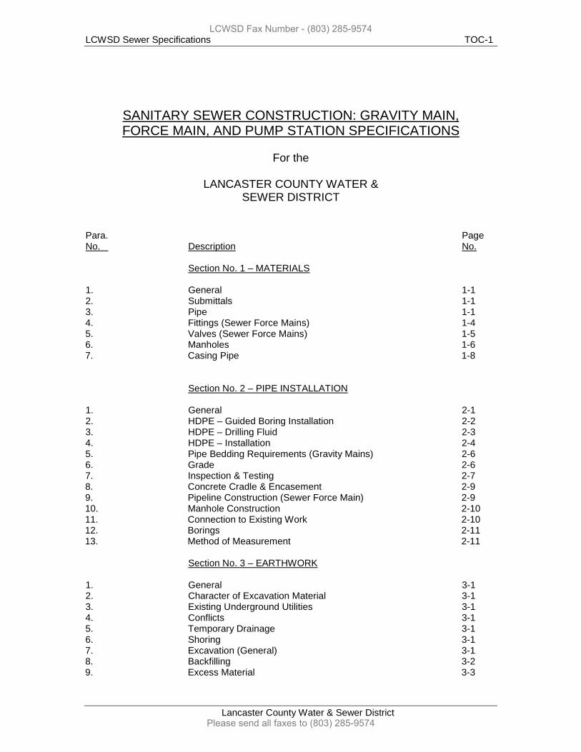
LCWSD Sewer Specifications TOC-1
Lancaster County Water & Sewer District
SANITARY SEWER CONSTRUCTION: GRAVITY MAIN, FORCE MAIN, AND PUMP STATION SPECIFICATIONS
For the
LANCASTER COUNTY WATER &
SEWER DISTRICT Para. Page No. Description No. Section No. 1 – MATERIALS 1. General 1-1 2. Submittals 1-1 3. Pipe 1-1 4. Fittings (Sewer Force Mains) 1-4 5. Valves (Sewer Force Mains) 1-5 6. Manholes 1-6 7. Casing Pipe 1-8 Section No. 2 – PIPE INSTALLATION 1. General 2-1 2. HDPE – Guided Boring Installation 2-2 3. HDPE – Drilling Fluid 2-3 4. HDPE – Installation 2-4 5. Pipe Bedding Requirements (Gravity Mains) 2-6 6. Grade 2-6 7. Inspection & Testing 2-7 8. Concrete Cradle & Encasement 2-9 9. Pipeline Construction (Sewer Force Main) 2-9 10. Manhole Construction 2-10 11. Connection to Existing Work 2-10 12. Borings 2-11 13. Method of Measurement 2-11 Section No. 3 – EARTHWORK 1. General 3-1 2. Character of Excavation Material 3-1 3. Existing Underground Utilities 3-1 4. Conflicts 3-1 5. Temporary Drainage 3-1 6. Shoring 3-1 7. Excavation (General) 3-1 8. Backfilling 3-2 9. Excess Material 3-3
LCWSD Fax Number - (803) 285-9574
Please send all faxes to (803) 285-9574
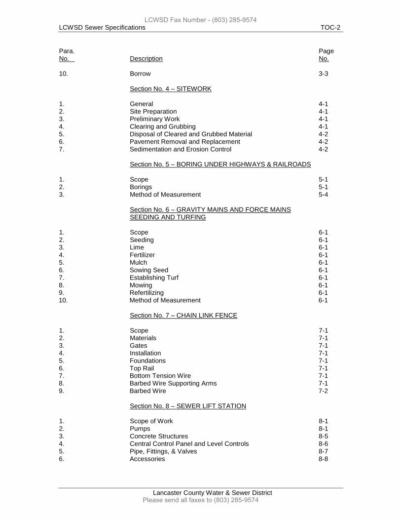
LCWSD Sewer Specifications TOC-2
Lancaster County Water & Sewer District
Para. Page No. Description No. 10. Borrow 3-3 Section No. 4 – SITEWORK 1. General 4-1 2. Site Preparation 4-1 3. Preliminary Work 4-1 4. Clearing and Grubbing 4-1 5. Disposal of Cleared and Grubbed Material 4-2 6. Pavement Removal and Replacement 4-2 7. Sedimentation and Erosion Control 4-2 Section No. 5 – BORING UNDER HIGHWAYS & RAILROADS 1. Scope 5-1 2. Borings 5-1 3. Method of Measurement 5-4 Section No. 6 – GRAVITY MAINS AND FORCE MAINS SEEDING AND TURFING 1. Scope 6-1 2. Seeding 6-1 3. Lime 6-1 4. Fertilizer 6-1 5. Mulch 6-1 6. Sowing Seed 6-1 7. Establishing Turf 6-1 8. Mowing 6-1 9. Refertilizing 6-1 10. Method of Measurement 6-1 Section No. 7 – CHAIN LINK FENCE 1. Scope 7-1 2. Materials 7-1 3. Gates 7-1 4. Installation 7-1 5. Foundations 7-1 6. Top Rail 7-1 7. Bottom Tension Wire 7-1 8. Barbed Wire Supporting Arms 7-1 9. Barbed Wire 7-2 Section No. 8 – SEWER LIFT STATION 1. Scope of Work 8-1 2. Pumps 8-1 3. Concrete Structures 8-5 4. Central Control Panel and Level Controls 8-6 5. Pipe, Fittings, & Valves 8-7 6. Accessories 8-8
LCWSD Fax Number - (803) 285-9574
Please send all faxes to (803) 285-9574
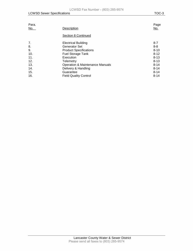
LCWSD Sewer Specifications TOC-3
Lancaster County Water & Sewer District
Para. Page No. Description No. Section 8 Continued 7. Electrical Building 8-7 8. Generator Set 8-8 9. Product Specifications 8-10 10. Fuel Storage Tank 8-12 11. Execution 8-13 12. Telemetry 8-13 13. Operation & Maintenance Manuals 8-14 14. Delivery & Handling 8-14 15. Guarantee 8-14 16. Field Quality Control 8-14
LCWSD Fax Number - (803) 285-9574
Please send all faxes to (803) 285-9574
LCWSD Sewer Specifications 1-1
Lancaster County Water & Sewer District
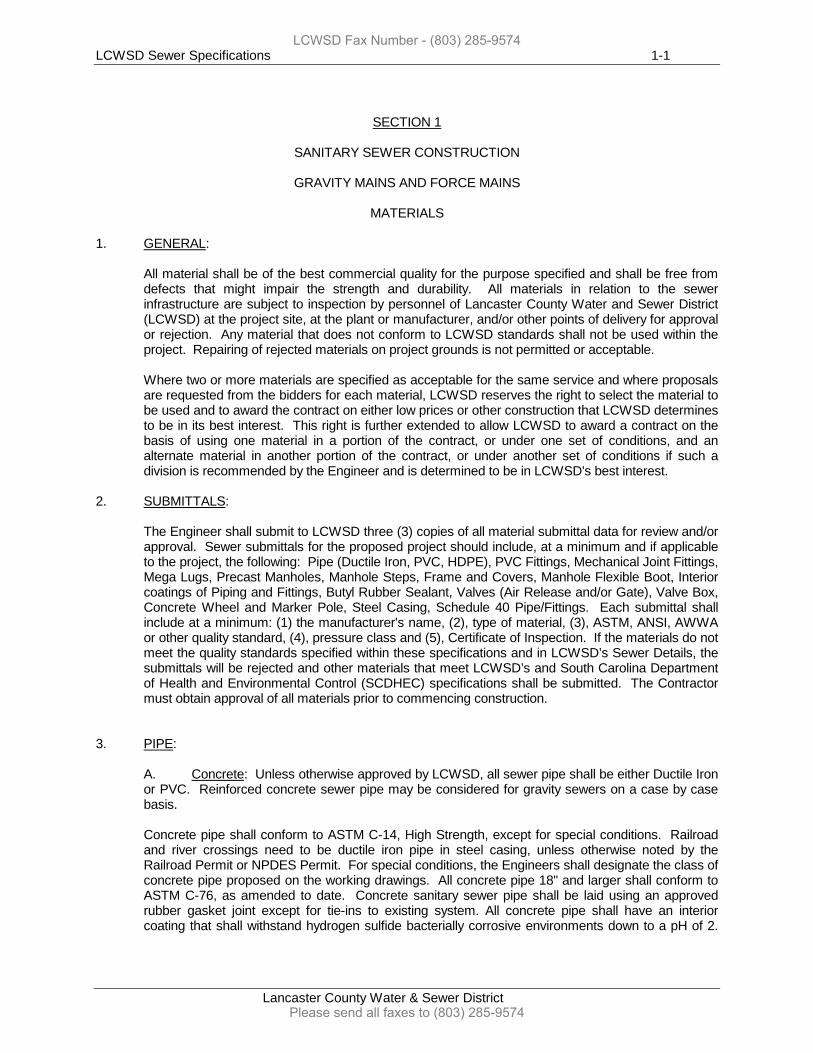
SECTION 1
SANITARY SEWER CONSTRUCTION
GRAVITY MAINS AND FORCE MAINS MATERIALS
1. GENERAL:
All material shall be of the best commercial quality for the purpose specified and shall be free from defects that might impair the strength and durability. All materials in relation to the sewer infrastructure are subject to inspection by personnel of Lancaster County Water and Sewer District (LCWSD) at the project site, at the plant or manufacturer, and/or other points of delivery for approval or rejection. Any material that does not conform to LCWSD standards shall not be used within the project. Repairing of rejected materials on project grounds is not permitted or acceptable.
Where two or more materials are specified as acceptable for the same service and where proposals are requested from the bidders for each material, LCWSD reserves the right to select the material to be used and to award the contract on either low prices or other construction that LCWSD determines to be in its best interest. This right is further extended to allow LCWSD to award a contract on the basis of using one material in a portion of the contract, or under one set of conditions, and an alternate material in another portion of the contract, or under another set of conditions if such a division is recommended by the Engineer and is determined to be in LCWSD's best interest.
2. SUBMITTALS:
The Engineer shall submit to LCWSD three (3) copies of all material submittal data for review and/or approval. Sewer submittals for the proposed project should include, at a minimum and if applicable to the project, the following: Pipe (Ductile Iron, PVC, HDPE), PVC Fittings, Mechanical Joint Fittings, Mega Lugs, Precast Manholes, Manhole Steps, Frame and Covers, Manhole Flexible Boot, Interior coatings of Piping and Fittings, Butyl Rubber Sealant, Valves (Air Release and/or Gate), Valve Box, Concrete Wheel and Marker Pole, Steel Casing, Schedule 40 Pipe/Fittings. Each submittal shall include at a minimum: (1) the manufacturer's name, (2), type of material, (3), ASTM, ANSI, AWWA or other quality standard, (4), pressure class and (5), Certificate of Inspection. If the materials do not meet the quality standards specified within these specifications and in LCWSD’s Sewer Details, the submittals will be rejected and other materials that meet LCWSD’s and South Carolina Department of Health and Environmental Control (SCDHEC) specifications shall be submitted. The Contractor must obtain approval of all materials prior to commencing construction.
3. PIPE:
A. Concrete: Unless otherwise approved by LCWSD, all sewer pipe shall be either Ductile Iron or PVC. Reinforced concrete sewer pipe may be considered for gravity sewers on a case by case basis. Concrete pipe shall conform to ASTM C-14, High Strength, except for special conditions. Railroad and river crossings need to be ductile iron pipe in steel casing, unless otherwise noted by the Railroad Permit or NPDES Permit. For special conditions, the Engineers shall designate the class of concrete pipe proposed on the working drawings. All concrete pipe 18" and larger shall conform to ASTM C-76, as amended to date. Concrete sanitary sewer pipe shall be laid using an approved rubber gasket joint except for tie-ins to existing system. All concrete pipe shall have an interior coating that shall withstand hydrogen sulfide bacterially corrosive environments down to a pH of 2.
LCWSD Fax Number - (803) 285-9574
Please send all faxes to (803) 285-9574
LCWSD Sewer Specifications 1-2
Lancaster County Water & Sewer District
Lining shall be Sewpercoat, Strong Seal, Quadex, Protecto 401, or approved equal. Please refer to the Lining Specification.
B. Ductile Iron: Pipe shall be centrifugally cast and shall conform to the requirements of ANSI A21.51 (AWWA C151) as amended to date and laying lengths of at least 18’ with minimum Class 200 wall thickness or as required by the installation conditions (i.e., depth of cover, trench type, etc.). The class of pipe required shall be verified by the Engineer indicating the pipe class required for the installation conditions and detailed within the pipe submittal.
1. Joints: Mechanical ASA Specifications A21.11 (AWWA C111) as amended to date. Push on single gasket conforming to Federal Specifications WW-P-421b, Type II.
2. Pipe Lining: Pipe shall be cement-lined (standard thickness) inside the pipe. The cement lining shall be a cement mortar with a bituminous seal coat conforming to ANSI A21.4 (AWWA C104), as amended to date. For pipe sizes 6” or larger, interior coating shall withstand hydrogen sulfide bacterially corrosive environments down to a pH of 2. Lining shall be Sewpercoat, Strong Seal, Quadex, Protecto 401, or approved equal. Please refer to the Lining Specification.
3. Exterior Coating: Bituminous coating in accordance with manufacturer's specifications. 4. Marking: The class designations for the various classes of pipe shall be casted or stamped on the outside of each joint of pipe. Weights of the pipe (which shall conform strictly to ANSI regulations) shall also be stamped clearly and easily seen on the outside of each joint of pipe. 5. Certification: The Engineer and/or Contractor shall furnish LCWSD with certified reports stating that inspection and specified tests have been made and that the results comply with the applicable ANSI specification.
C. PVC Pipe (Gravity Sewers): All PVC Pipe shall conform to ASTM D-3034 (as amended to date), under the classification for SDR 35. PVC pipe shall be bell and spigot pipe, and shall be supplied in standard laying lengths (i.e., 14 ft. and/or 20 ft.). For PVC pipe that is 18” or greater, pipe must conform to ASTM F679, as amended to date.
1. Joints: All joints shall use a rubber gasketed system conforming to ASTM F 477, as amended to date. Joints shall meet the requirements specified in ASTMD 3212, as amended to date.
2. Installation: Pipe and fittings will be in accordance with ASTM D-2321, as amended to date. Only Class I, II, III embedment materials will be considered suitable for PVC applications.
3. Fittings: All fittings shall conform to ASTM D1784. 4. Marking: PVC pipe shall be plainly marked at five (5) ft. intervals or less including, at a minimum, the manufacturer’s name or trademark, plan code, date of manufacture, nominal pipe size, PVC cell classification, SDR 35 PVC, and ASTM designation of ASTM D – 3034. 5. Certification: The Engineer and/or Contractor shall furnish LCWSD with a written certification from the manufacturer that all pipe for the proposed project has been sampled, tested and inspected in accordance with ASTM D 3034, as amended to date. The certification must be signed by an authorized agent of the manufacturer.
LCWSD Fax Number - (803) 285-9574
Please send all faxes to (803) 285-9574
LCWSD Sewer Specifications 1-3
Lancaster County Water & Sewer District
D. PVC Pipe (Sewer Force Mains): PVC Pipe shall be SDR 21 or as otherwise directed by LCWSD.
1. Standards: PVC pipe used for construction shall comply to the following standards:
a. Standard dimension ratio - ASTM D 2241 200 psi pipe SDR 21 b. Grade 1 PVC Compound Material - ASTM D 1869 c. Rubber Coupling Rings - ASTM D 1599 d. Burst Pressure Test, 150 psi - ASTM D 1599 200 psi, SDR-21-minimum quick burst pressure 800 psi e. Impact Strength - ASTM D 2444
2. Installation: Pipe and fittings will be in accordance with the above standards, as amended to date. Only Class I, II, III embedment materials will be considered suitable for PVC applications. All sewer force mains shall have 12 gauge stranded coated tracer wire duct taped to top of the force main line for future locating purposes. 3. Marking: The pipe shall be plainly marked with the following information: manufacturer's name, nominal pipe size, material (PVC) type and grade or compound, NSF Seal, pressure rating and reference to appropriate product standards. 4. Certification: The Engineer and/or Contractor shall furnish LCWSD with a written certification from the manufacturer that all pipe for the proposed project has been sampled, tested and inspected in accordance with ASTM D 3034, as amended to date. The certification must be signed by an authorized agent of the manufacturer.
E. High Density Polyethylene Pipe:
1. General: Materials used for the manufacturing of polyethylene pipe and fittings shall be PE 3408 High Density Polyethylene (HDPE) meeting the ASTM D3350 cell classification of 345434C.
High Density Polyethylene Pipe (HDPE) and fittings will be used in accordance with the materials specifications. All additional appurtenances such as tees, gaskets, flange adaptors, etc. will meet the material specifications. Unless specified otherwise by LCWSD, the contractor will supply the pipe and fittings and will include its price in the bid. All pipe installed by guided boring will be joined by an approved butt fusion or electrofusion technique according to the manufacturer’s specifications.
HDPE pipe shall be produced from resins with a material designation PE3408, and a cell classification PE334434 as specified within ASTM D3350, and dimensions and workmanship as specified by ASTM F714. It will also meet the requirements of AWWA ASTM D3350.
The material shall be approved by the National Sanitation Foundation (NSF)
2. Installation: The installation of HDPE pipe and fittings must be in accordance of the most recent standards listed in High Density Polyethylene Pipe Sections in Section 1 and Section 2 of these sewer standard specifications. All HDPE pipe shall have 12-gauge stranded coated tracer wire duct taped to the top of the pipe or pulled through with the pipe when directional boring.
LCWSD Fax Number - (803) 285-9574
Please send all faxes to (803) 285-9574
LCWSD Sewer Specifications 1-4
Lancaster County Water & Sewer District
3. Pipe Thickness: The material shall have a minimum Hydrostatic Design Basis (HDB) of 1600 psi at 73° F when tested in accordance with PPI TR-3 and shall be listed in the name of the pipe and fitting manufacturer in PPI TR-4.
Polyethylene pipe shall be manufactured in accordance with AWWA C906 for sizes 4” through 63”.
4. Joints: Butt fusion or electrofusion welded in accordance with ASTM D3261.
5. Marking: Pipe will be legibly marked at intervals of no more than five feet with the manufacturer’s name, trademark, pipe size, HDPE cell classification, appropriate legend, such as SDR 11, ASTM D3035, AWWA C901 or C906, date of manufacture and point of origin. Permanent identification of piping service shall be provided by co-extruding longitudinal green stripes, for indication of a sewer line, into the pipes outside surface. The striping material shall be the same material as the pipe material except for color. Pipe not marked as indicated above will be rejected. 6. Certification: The Engineer and/or Contractor shall furnish LCWSD with a written certification from the manufacturer that all pipe for the proposed project has been sampled, tested and inspected in accordance with approved standards, as amended to date. The certification must be signed by an authorized agent of the manufacturer.
F. Steel Casing: Refer to Casing Pipe in this Section, number 7, for the specifications on steel casing pipe. All existing and improved roads, railroads, and highway crossings shall be cased in steel pipe according to the specifications of LCWSD and also to the specifications of the governing Agency (i.e., SCDOT, Norfolk Southern, L&C Railroad, etc.). G. Service Connection: The 4" and 6" pipe and fittings used for service connections shall be Schedule 40 PVC conforming to ASTM D-2466. Submittals for service connection materials to be used shall be submitted to LCWSD before construction begins.
1. Installation: All newly installed sewer services shall use either a Romac sewer service saddle with a 12” stainless universal band or an in-line PVC sewer service tee. The tee shall be 8” - Schedule 35 by 4” - Schedule 40 hub. The 8” ends shall be gasketed to slide over the 8” - Schedule 35 sewer main line. The 4” - Schedule 40 hub shall be manufactured so that the 4” - schedule 40 PVC pipe can be glued into the hub with no additional fittings needed. The 4” service connection shall be no deeper than 5’ from existing grade to the end of the service connection, unless otherwise approved by LCWSD Inspector. Some low elevated properties may require the end of the service connection to be deeper than the 5’ requirement to connect to the gravity sewer. Required fall from the end of the service connection to the customer’s structure is 1’ of fall per 100’ of distance to the structure for a 4” line. For a 6” line, the required fall from the end of the service connection to the customer’s structure is 6” of fall per 100’ of distance to the structure.
4. FITTINGS (Sewer Force Mains):
A. Ductile Iron: Ductile iron special castings or fittings shall be all mechanical joint. The special castings or fittings shall be manufactured in strict accordance with the latest revision of Specifications ANSI A21.53 (AWWA C153), with the exception of the manufacturer's design dimensions and thickness. Fittings shall have a working pressure rating of 350 psi for fittings 12” and under and 250 psi for fittings over 12”. Manufacturer of ductile iron fittings shall be at the discretion of LCWSD.
LCWSD Fax Number - (803) 285-9574
Please send all faxes to (803) 285-9574
LCWSD Sewer Specifications 1-5
Lancaster County Water & Sewer District
1. Lining: All ductile iron fittings shall be cement - lined with one-half thickness of cement (standard thickness), in the interior of the fitting, commonly known as "enameling" and have a bituminous coating both inside and out. For pipe sizes 6” or larger, interior coating shall withstand hydrogen sulfide bacterially corrosive environments down to a pH of 2. Lining shall be Sewpercoat, Strong Seal, Quadex, Protecto 401, or approved equal. 2. Marking: The class designations for the various classes of pipe shall be cast in raised numerals on the outside of each fitting. Weights of the fitting (which shall conform strictly to ANSI regulations) shall be stamped clearly and easily seen on the outside of each fitting. 3. Certification: The Engineer and/or Contractor shall furnish LCWSD with certified reports stating that inspection and specified tests have been made and that the results comply with the applicable ANSI specification.
5. VALVES (Sewer Force Mains): A. Gate Valves:
1. All gate valves shall be manufactured with a resilient seat and designed and manufactured in accordance with the requirements of the latest revision of AWWA C-509. Gate valves shall be manufactured by Mueller, American Flow Control, or approved equal will only be approved by LCWSD. 2. All valves shall be of iron body, bronze mounted, double disc parallel seat type with non-rising stems and a 2" square operating nut. Valves 16" and larger shall have a by-pass to equalize pressure on both of the valves to facilitate opening. All valves 24" and larger shall be equipped with gearing. All valves shall turn to the left for opening of valve.
3. Valve ends shall be of the size and type required for connections to the type service line used. Standard connections shall be push-on with gaskets for PVC pipe, or M.J. for DI pipe.
Pressure ratings for the valves shall be as follows: WORKING HYDROSTATIC TEST SIZE PRESSURE PRESSURE (SHELL) 2" - 12" 200 psi 400 psi 14" - 24" 150 psi 300 psi
B. Air Release Valves: LCWSD accepts GA Industries, Crispin Valves, Val-Matic or approved equal. The valve shall have a shut-off or gate valve located in a separate valve box between the force main line and the air release valve. All Air Release Valves shall have a pre-cast concrete manhole cone (with steps in manhole for access) and a ring and cover over them for access purposes. The manhole shall be installed where the top of the manhole is flush with final grade. Refer to the pre-cast manhole section for material specification details. 1. Installation: All valves shall have a minimum 12” of #57 wash stone under the valve for drainage purposes. All valves shall be located by installing a concrete protector wheel around the separate valve box and a concrete marker pole at the valve with the letters ARV pointed towards the valve.
LCWSD Fax Number - (803) 285-9574
Please send all faxes to (803) 285-9574
LCWSD Sewer Specifications 1-6
Lancaster County Water & Sewer District
2. Standard Sewage Air Release Valve: Valve shall be float operated and shall employ a compound lever mechanism to enable the valve to automatically release accumulated air and gases from a sewage pipeline while the system is pressurized and operating. The Air Release Valve shall close drop tight, incorporating an adjustable Buna-N orifice button. All internal metal parts shall be of stainless steel. The linkage/lever mechanism shall be able to be removed from the valve without disassembly of the mechanism. The float shall be stainless steel and be capable of withstanding a 1000 PSIG test pressure. The body and cover shall be of cast iron conforming to ASTM A126 Class B. Inlet connection shall be 2” or 3” NPT, or 4” FLG, as required. Outlet connection shall be ½” NPT. The valve shall be supplied with a “flushing attachment” consisting of: bronze shut-off valves, quick-connect couplings and rubber hose, for backwashing with clear water. The Air Release Valve shall conform to AWWA Standard C512. GA Industries Model 925, Crispin SL Series, Val-Matic Series 48ABW, or approved equal will only be accepted.
3. Sewage Air/Vacuum Valve – The valve shall automatically exhaust large quantities of air and gases while the pipeline or system is being filled and allow air to re-enter during draining or when a negative pressure exists. The valve shall be spherical float operated and shall close drop tight against a renewable rubber seat. All internal parts shall be made of stainless steel. Body and cover shall be of cast iron conforming to ASTM A126, Class B. Inlet connection shall be NPT to 3” size, CL. 125 FLG in 4” and larger. Outlet shall be NPT. When specified, valve shall be supplied with “flushing attachment” consisting of: bronze shut-off and flushing valves, quick connect coupling and 5 ft. of rubber hose, for backwashing with clear water. The valve shall be supplied with a “flushing attachment” consisting of bronze shut-off valves, quick-connect couplings and rubber hose, for backwashing with clear water. GA Industries Model 935, Crispin S Series, Val-Matic Series #301ABW, or approved equal will only be accepted.
4. Standard Custom Sewage Combination Air Valve: The valve assembly shall be designed to exhaust large amounts of air during filling, release small amounts of accumulated air during operation and open upon impending vacuum to admit large amounts of air while draining. The valve assembly shall consist of two independent valves: a large orifice Air & Vacuum Valve and a small orifice Air Release Valve, piped together so that a single, common connection can be made to the force main. The assembly shall be tested as a unit to insure there are no leaking joints. All necessary fittings between the two valves shall be either brass or Sch. 40 PVC. All internal metal trim components shall be stainless steel. The Combination Air Valve shall be supplied with “flushing attachment” to allow periodic flushing of sediment, grease and solids. Attachments consist of: bronze blow-off and flushing valves, with a minimum of 5 ft. of rubber hose, and quick disconnects to allow connection to a clean water source. GA Industries Model 942, Val-Matic Series 802ABW, or approved equal will only be accepted.
C. Valve Boxes: Adjustable valve boxes shall be of quality and workmanship to those manufactured by Mueller Company, East Jordan Iron Works, or Resselaer Valve Company or an approved equal. Valve boxes shall be of close-grained gray cast iron. The valve boxes shall be the two piece screw type and the cover or cap shall have cast on the upper surface in raised letters the word "Sewer". Valve boxes shall be painted with a coat of protective asphaltum paint before being shipped from the factory. Concrete protector rings shall be placed ground level around all valve boxes with concrete marker poles installed with the letters of the marker pole to show the direction and placement of all valves.
6. MANHOLES: Manholes shall be built of pre-cast concrete sections only.
A. Pre-cast Concrete Manholes: Pre-cast Concrete Manholes sections shall conform to ASTM C478 latest revision. The successful bidder shall submit three copies of shop drawings of the pre-
LCWSD Fax Number - (803) 285-9574
Please send all faxes to (803) 285-9574
LCWSD Sewer Specifications 1-7
Lancaster County Water & Sewer District
cast manholes proposed to be used for approval to LCWSD and Engineer before ordering the manholes for the proposed project. Pre-cast manholes with preformed bottoms shall be set on a minimum of 6" of gravel or stone base. The stone or gravel base shall be placed over an area not less than 7'x 7' centered on the centerline of the proposed manhole location. All manholes shall have installed at the pre-cast manufacturer, a set of steps as described in the next section. All pre-cast manholes shall have pre-cast inverts installed at the manufacturer unless the Contractor is tying into an existing sewer main line and the need for a “doghouse” type base section is needed. All pre-cast manholes shall be manufactured to meet or exceed the latest ASTM C-478 reinforcement requirement and have a 28 day compressive strength factor of 4,500 psi. All pre-cast manholes shall be manufactured with the desired cored openings as required when possible. All manholes that will be receiving sewer from a proposed sewer force main will be required to have the manhole manufacturer or an approved Contractor by LCWSD to install interior coating which shall withstand hydrogen sulfide bacterially corrosive environments down to a pH of 2. Lining shall be Raven 405, Sprayroq (Osborn Contracted Services, Inc.) or approved equal. Repaired and patched sections of a precast manhole will not be acceptable unless each individual sections repaired or patched has been inspected and approved by the engineer of manhole manufacturer or by LCWSD’s inspector. Repairs to and patching of O-ring grooves and shoulders will not be permitted. B. Steps: All pre-cast manholes shall have co-polymer polypropyene steel reinforced steps meeting the latest version of ASTM-478. All steps shall be located at the same position or angle in all sections of the manhole so that the steps shall be aligned straight. All steps shall be located over either bench in the manhole and not over any invert. Manhole steps shall be placed inside of the manhole if it is more than 4’ in depth. Manhole steps shall be 15” apart beginning 2’ from the bottom and ending 3’ from the top of the manhole casting. The steps shall be pre-cast in the manhole, thoroughly bonded, accurately spaced, and aligned. For manholes that are greater than 3’ above finish ground level, steps must be cast into the outside of the manhole cone for access to the frame and cover. Steps shall be spaced and aligned equally, as similar to the steps inside the manhole. C. Manhole Frames and Covers: Manhole frames and covers shall be designed for heavy traffic weighing not less than 310 lbs and shall be proof load tested to hold a 40,000 proof load for one minute without experiencing any cracks or detrimental permanent deformation. The iron shall be tough, dense, and even grained, cast in a true symmetrical pattern free from defects of any kind, as stated in the latest revision of Section 4 of AASHTO M306-07. Approved frames and covers manufacturers are: US Foundry, East Jordan Iron Works, or approved equal by LCWSD. All covers shall be inter-changeable with any frames LCWSD may currently own.
Ductile iron castings shall be manufactured from iron conforming to ASTM A536 grade 80-55-06 as noted in section 3.2 of AASHTO M306-07. Cast iron castings shall be manufactured from iron conforming to ASTM A48 Class 35B as noted in section 3.1 of AASHTO M306-07. The iron material used in products provided shall have a minimum recycled material content of 75%. The recycled materials shall consist of post-consumer material. Certification: A foundary certification shall be furnished to LCWSD stating that samples representing each lot have been tested and inspected and are in accordance with the specification. Marking: Each casting shall be identifiable and show, at a minimum, the following: lettered with “LCWSD” and “Sanitary Sewer”, name of the producing foundary, country of manufacture (“Made in USA”), ASTM A536 DI, individual part number, and cast or heat date.
1. Revolutionary Manhole Frame & Cover: The Revolutionary Manhole Frame & Cover must be used for elevated manholes that are 3’ above grade level. The Revolution frame and cover may not be used in roadways. If the manhole is in the 100-year flood plain
LCWSD Fax Number - (803) 285-9574
Please send all faxes to (803) 285-9574
LCWSD Sewer Specifications 1-8
Lancaster County Water & Sewer District
zone, then the frames and covers must be watertight (i.e., bolted and sealed). The Revolution frames and covers shall be manufactured in the United States of America by East Jordan Iron Works, Inc. or approved equal by LCWSD. The cover shall rotate horizontally away from the frame, allowing access to the manhole. The gray iron castings shall be manufactured from iron conforming to AASHTO M105, Class 35B. The iron material used in products provided shall have a minimum recycled material content of 75%. The recycled materials shall consist of post-consumer and/or post-industrial material. Certification: A foundary certification shall be furnished to LCWSD, prior to installation, stating that test bar samples representing each lot have been tested and inspected and are in compliance with LCWSD’s specifications. Inspection of the castings shall be in accordance with AASHTO M105. Results of the tests shall be furnished to LCWSD, if requested. Markings: Each frame and cover shall be identifiable and show, at a minimum, the following: the lettering of “LCWSD” and Sanitary Sewer, name of the producing foundary, country of the manufacture (“Made in USA”), ASTM A48, CL35B, individual part number, and cast or heat date.
D. Connection of Pipe to Manhole: The connection of the pipe to the manhole shall be with a flexible joint system. The flexible joint system shall be a neoprene or synthetic rubber boot or sleeve, either cast or core drilled in the wall of the manhole. The boot or sleeve system shall be clamped and sealed to the pipe with a stainless steel band. The boot or sleeve system must be submitted to LCWSD for approval.
7. CASING PIPE:
A. Boring Under Paved Roads and Highways: The inside diameter of the casing pipe shall not be less than 2" greater than the largest outside diameter of the joints and couplings for carrier pipe that is less than 6" O.D. For carrier pipe that is 6” and larger, the inside diameter of the casing shall not be less than 4” greater than the outside diameter of the carrier pipe, couplings, etc. Casing pipe shall, in all cases, be great enough in diameter to easily remove carrier pipe and casing spiders without disturbing the casing pipe. The Contractor should contact the local South Carolina Department of Transportation for any questions and permitting for any road or highway bores. Casing spiders shall be installed by the contractor to center the carrier pipe inside the casing pipe. Casing spiders shall be stainless steel unless approved otherwise by LCWSD staff.
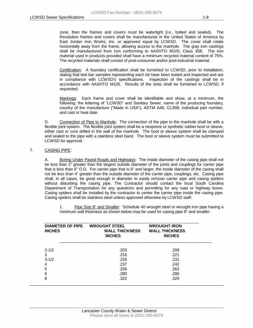
1. Pipe Size 8" and Smaller: Schedule 40 wrought steel or wrought iron pipe having a minimum wall thickness as shown below may be used for casing pipe 8" and smaller.
_____________________________________________________________________ DIAMETER OF PIPE WROUGHT STEEL WROUGHT IRON INCHES WALL THICKNESS WALL THICKNESS INCHES INCHES ____________________________________________________________________
2-1/2 .203 .208 3 .216 .221 3-1/2 .226 .231 4 .237 .242 5 .258 .263 6 .280 .286 8 .322 .329
LCWSD Fax Number - (803) 285-9574
Please send all faxes to (803) 285-9574
LCWSD Sewer Specifications 1-9
Lancaster County Water & Sewer District
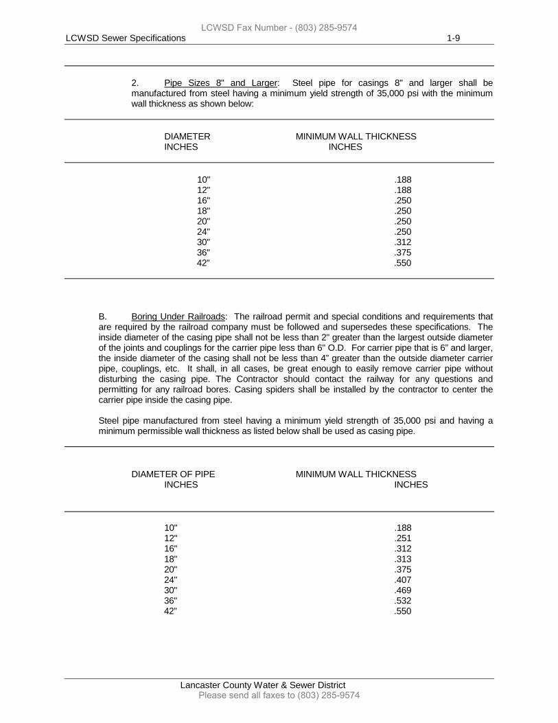
2. Pipe Sizes 8" and Larger: Steel pipe for casings 8" and larger shall be manufactured from steel having a minimum yield strength of 35,000 psi with the minimum wall thickness as shown below:
DIAMETER MINIMUM WALL THICKNESS INCHES INCHES 10" .188 12" .188 16" .250 18" .250 20" .250 24" .250 30" .312 36" .375 42” .550
B. Boring Under Railroads: The railroad permit and special conditions and requirements that are required by the railroad company must be followed and supersedes these specifications. The inside diameter of the casing pipe shall not be less than 2" greater than the largest outside diameter of the joints and couplings for the carrier pipe less than 6" O.D. For carrier pipe that is 6” and larger, the inside diameter of the casing shall not be less than 4” greater than the outside diameter carrier pipe, couplings, etc. It shall, in all cases, be great enough to easily remove carrier pipe without disturbing the casing pipe. The Contractor should contact the railway for any questions and permitting for any railroad bores. Casing spiders shall be installed by the contractor to center the carrier pipe inside the casing pipe.
Steel pipe manufactured from steel having a minimum yield strength of 35,000 psi and having a minimum permissible wall thickness as listed below shall be used as casing pipe.
DIAMETER OF PIPE MINIMUM WALL THICKNESS INCHES INCHES 10" .188 12" .251 16" .312 18" .313 20" .375 24" .407 30" .469 36" .532 42” .550
LCWSD Fax Number - (803) 285-9574
Please send all faxes to (803) 285-9574
LCWSD Sewer Specifications 2-1
Lancaster County Water & Sewer District
SECTION 2
SANITARY SEWER CONSTRUCTION
GRAVITY MAINS AND FORCE MAINS PIPE INSTALLATION 1. GENERAL: The Contractor shall confirm and approve the grade of pipe with the Engineer or a
designated authoritative inspector approved by the LCWSD prior to installation of the pipe. Any pipe installed without the approval of the Engineer or a designated authoritative inspector approved by the LCWSD shall be removed and relayed if directed.
Whenever the Engineer authorizes the use of wood blocks or "Mud Sills" for supporting the pipe, such sills shall be at least 6" longer than the O.D. of the pipe and in section shall be at least 2" by 10" for 12" and larger pipe. No extra compensation shall be allowed for the use of such material.
Pipe shall not be laid in water, and water shall not be allowed to flow against or over the joints until they have properly set. Construction operations in rivers, streams, and impoundments shall be restricted only to those areas which must be entered for the construction of temporary or permanent structures. As soon as conditions permit, river, streams, and impoundments shall be promptly cleared of all construction material, including any debris, piling, etc., and placed back into normal operation. Temporary bridges or other structures shall be used wherever stream crossings are required. Frequent fording of live streams are not permitted.
The pipe shall be so laid in the trench such that after the sewer is completed, the invert of the pipe shall conform accurately to line and grade.
Prior to the pipe being lowered into the trench, each pipe shall be carefully inspected by the contractor’s foreman and/or LCWSD’s inspector, and all faulty pipe shall be rejected and removed from the job-site. Pipe or any other construction material must not be repaired on site, unless otherwise approved by the LCWSD Inspector and/or Engineer.
A bell hole shall be dug for each joint of pipe. Bell holes shall be no larger than necessary for making the joint. The bottom of the trench shall be shaped to fit the bottom quarter of the pipe to insure a firm even bearing on undisturbed earth of the entire length of the pipe.
The interior of the bell of the last pipe laid and the spigot of the next pipe shall be wiped clean and dry as each joint is laid.
Rubber gaskets shall be installed, lubricated and protected strictly as recommended by the pipe and/or gasket manufacturer. In case pressure from the compressed gasket tends to open the joint after it is made, the Contractor will provide a positive means of holding pipe joints after installation to hold the joint as made. Restraining gaskets (Field Lock gaskets or approved equal) may be used in situations when the piping infrastructure needs to be restrained; however, the restraining gaskets need to be approved per situation by LCWSD’s engineer or LCWSD’s consulting engineer.
All sewer gravity main lines that are 3’ to 14’ in depth shall use PVC SDR 35 piping unless otherwise noted. All lines over 14’ in depth shall have interior coated ductile iron piping (see Section 1-3). Gravity sewer lines that are 0’-3’ in depth must be approved by the South Carolina Department of Health and Environmental Control with their approval on material and installation procedures. LCWSD may require interior coated ductile iron piping under these depth conditions. Any gravity sewer or forcemain installed under a South Carolina Department of Transportation road or a County road must be placed per their requirements.
LCWSD Fax Number - (803) 285-9574
Please send all faxes to (803) 285-9574
LCWSD Sewer Specifications 2-2
Lancaster County Water & Sewer District
2. HDPE – Guided Boring Installation:
A. Scope: This section includes the installation of the sewer main by guided boring. The contractor will furnish all labor, components, materials, tools, and appurtenances necessary or proper for the performance and completion of the contract.
B. General Description of Method: Guided boring is a method of trenchless construction using a surface launched steerable drilling tool controlled from a mobile drilling frame, and includes a field power unit, mud mixing system, and mobile spoils extraction system. The drilling frame is sited and aligned to bore a pilot borehole that conforms to the planned installation of the main. The drilling frame is set back from an access pit that has been dug (typically at the location of the proposed sewer main or other appurtenances) and a high-pressure fluidjet toolhead that uses a mixture of bentonite clay and water is launched. Pits are normally dug at the start point and endpoint of the proposed pipe installation and are used to align the toolhead, attach other equipment, and to collect and remove excess spoils. Using an electronic guidance system, the toolhead is guided through the soil to create a pilot borehole. Upon reaching the endpoint joint, the toolhead is removed and a reamer with the product pipe attached is joined to the drill string and pulled back through the borehole. In large diameter installations, pre-reaming of the borehole will usually be done prior to attaching the product pipe for the final pullback. A vacuum spoils extraction system removes any excess spoils generated during the installation. The connections, manholes, or other appurtenances are then completed at both the start point and endpoint locations and the surface restored to its original condition.
C. Qualifications: 1. Guided boring contractors shall have actively engaged in the installation of
pipe using guided boring for a minimum of three (3) years. 2. Field supervisory personnel employed by the guided boring contractor must
have at least three (3) years experience in the performance of the work and tasks as stated in the contract document.
D. Submittals:
1. Submit documentation showing three (3) years of guided boring experience. Information must include, but not be limited to; date and duration of work, location, pipe information (i.e., length, diameter, depth of installation, pipe material, etc.), project owner information, (i.e., name, address, telephone number, contact person), and the contents handled by the pipeline (water, wastewater, etc.).
2. Submit a list of field supervisory personnel and their experience with guided boring operations. At least one (1) of the field supervisors listed must be at the site and be responsible for all work at all times when guided boring operations are in progress. Guided boring operations will not proceed until the resume(s) of the contractor’s field supervisory personnel have been received and reviewed by the Project Engineer and LCWSD.
3. Submit the following drawings and documents:
a. Working drawings and written procedure describing in detail the proposed method of installation. This will include, but not be limited to; size, capacity and setup requirements of equipment, location and siting of drilling and receiving pits, dewatering if applicable, method of fusion and type of equipment for joining pipe, type of cutting tool head, and method of
LCWSD Fax Number - (803) 285-9574
Please send all faxes to (803) 285-9574
LCWSD Sewer Specifications 2-3
Lancaster County Water & Sewer District
monitoring and controlling line and depth. If the contractor determines that modifications to the method and equipment as stated in the submittal is necessary during construction, the contractor will submit a plan describing such modifications, including the reasons for the modification.
b. Bentonite drilling mud products information (MSDS); special precautions necessary; method of mixing and application; and method of removing spoils.
E. Site Conditions:
1. Drilling operations must not interfere with, interrupt or endanger surface and activity upon the surface.
2. Contractor must comply with all applicable jurisdictional codes and OSHA requirements.
3. The contractor shall conduct pre-bid and pre-drill investigations of each individual site and make a determination as to the existing conditions.
4. When rock stratum, boulders, underground obstructions, or other soil conditions that impede the progress of drilling operations are encountered, the contractor shall change from a conventional drilling bit to one suitable for drilling in rock formations. This change in equipment shall be at no additional cost to LCWSD.
3. HDPE – Drilling Fluid:
A. Drilling fluid will be a mixture of water and bentonite clay. The fluid will be inert. The fluid should remain in the tunnel to ensure the stability of the tunnel, reduce drag on the pulled pipe, and provide backfill with the annulus of the pipe and tunnel.
B. Disposal of excess drilling fluid and spoils will be the responsibility of the contractor who must comply with all relevant regulations, right-of-way, work space, and permit agreements unless otherwise agreed upon before hand with LCWSD personnel. Excess drilling fluid and spoils will be disposed at an approved location.
C. The contractor is responsible for transporting all excess drilling fluid and spoils to the disposal site and paying any disposal costs. Excess drilling fluid and spoils will be transported in a manner that prevents accidental spillage onto roadways. Excess drilling fluid and spoils will not be discharged into sanitary or storm drain systems, ditches, or waterways. D. Drilling fluid returns (caused by fracturing of formations) at locations other than the entry and exit points will be minimized. The contractor will immediately clean up any drilling fluid which surfaces through fracturing. E. Mobile spoils removal equipment capable of quickly removing spoils from entry or exit pits and areas with returns caused by fracturing will be present during drilling operations to fulfill the requirements of paragraphs b and c above. F. The contractor will be responsible for making provisions for a clean water supply for the mixing of drilling fluid.
LCWSD Fax Number - (803) 285-9574
Please send all faxes to (803) 285-9574
LCWSD Sewer Specifications 2-4
Lancaster County Water & Sewer District
4. HDPE – Installation: A. General:
1. The Engineer shall be notified immediately if any obstruction is encountered that stops the forward progress of drilling operations. 2. The type of dewatering method will be at the option of the contractor. However, the dewatering of pits and excavations must meet all requirements of OSHA and the general conditions, special provisions, and specifications of LCWSD. When water is encountered, the contractor, unless otherwise agreed upon beforehand, must provide a dewatering system of sufficient capacity to remove water, keeping any excavations free of water until the backfill operation is in progress. Dewatering shall be performed in a manner that removal of soil particles is held to a minimum.
B. Preparation: 1. Excavate required pits in accordance with the working drawings.
2. The drilling procedures and equipment shall provide protection of workers, particularly against electrical shock. As a minimum, grounding mats, grounded equipment, hot boots, hot gloves, safety glasses, and hard hats shall be used by crewmembers. The drilling equipment shall have an audible alarm system capable of detecting electrical current. 3. Removal of trees, landscaping, pavement or concrete shall be performed by the contractor unless otherwise agreed upon beforehand.
C. Guided Boring Operations:
1. Equipment:
a. The drilling equipment must be capable of placing the pipe within the limits indicated on the contract plans. b. Guided boring equipment shall consist of a surface launched steerable drilling tool controlled from a mobile drilling frame, and include a field power unit, mud mixing system and mobile spoils extraction system. c. The number of access pits shall be kept to a minimum and the equipment must be capable of boring the following lengths in a single bore. The guided boring system will have the capacity of boring and installing a continuous run without intermediate pits of a minimum distance for the following pipe diameters: Product Pipe Size Minimum Boring Distance 1 – 1 ½ inches 500 feet 2 – 4 inches 450 feet 6 inches 400 feet 8 inches 350 feet 10-16 inches 300 feet d. The guidance system shall have the capability of measuring vertical (depth) position, horizontal position and roll. The guidance system must meet the following specifications in soft homogenous soils:
LCWSD Fax Number - (803) 285-9574
Please send all faxes to (803) 285-9574
LCWSD Sewer Specifications 2-5
Lancaster County Water & Sewer District
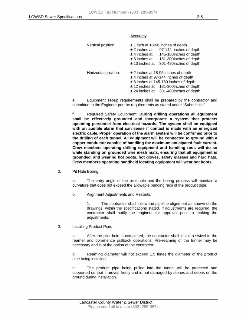
Accuracy Vertical position: ± 1 inch at 18-96 inches of depth ± 2 inches at 97-144 inches of depth ± 4 inches at 145-180 inches of depth ± 6 inches at 181-300 inches of depth ± 10 inches at 301-480 inches of depth Horizontal position: ± 2 inches at 18-96 inches of depth ± 4 inches at 97-144 inches of depth ± 6 inches at 145-180 inches of depth ± 12 inches at 181-300 inches of depth ± 24 inches at 301-480 inches of depth e. Equipment set-up requirements shall be prepared by the contractor and submitted to the Engineer per the requirements as stated under “Submittals.” f. Required Safety Equipment: During drilling operations all equipment shall be effectively grounded and incorporate a system that protects operating personnel from electrical hazards. The system shall be equipped with an audible alarm that can sense if contact is made with an energized electric cable. Proper operation of the alarm system will be confirmed prior to the drilling of each tunnel. All equipment will be connected to ground with a copper conductor capable of handling the maximum anticipated fault current. Crew members operating drilling equipment and handling rods will do so while standing on grounded wire mesh mats, ensuring that all equipment is grounded, and wearing hot boots, hot gloves, safety glasses and hard hats. Crew members operating handheld locating equipment will wear hot boots.
2. Pit Hole Boring:
a. The entry angle of the pilot hole and the boring process will maintain a curvature that does not exceed the allowable bending radii of the product pipe.
b. Alignment Adjustments and Restarts:
1. The contractor shall follow the pipeline alignment as shown on the drawings, within the specifications stated. If adjustments are required, the contractor shall notify the engineer for approval prior to making the adjustments.
3. Installing Product Pipe:
a. After the pilot hole is completed, the contractor shall install a swivel to the reamer and commence pullback operations. Pre-reaming of the tunnel may be necessary and is at the option of the contractor. b. Reaming diameter will not exceed 1.5 times the diameter of the product pipe being installed. c. The product pipe being pulled into the tunnel will be protected and supported so that it moves freely and is not damaged by stones and debris on the ground during installation.
LCWSD Fax Number - (803) 285-9574
Please send all faxes to (803) 285-9574
LCWSD Sewer Specifications 2-6
Lancaster County Water & Sewer District
d. Pullback forces will not exceed the allowable pulling forces for the product pipe. e. The contractor shall allow sufficient lengths of product pipe to extend past the termination point to allow connections to the diffuser assembly. Pulled pipe will be allowed 24 hours of stabilization prior to making tie-ins. The length of extra product pipe will be at the contractor’s discretion.
4. Clean-up:
The contractor shall maintain the work site in a neat and orderly condition throughout the period of work. After completing the work at each site, the contractor shall remove debris, surplus material, and temporary structures erected by the contractor. The site shall be restored to a condition equal to the existing condition prior to being disturbed.
5. PIPE BEDDING REQUIREMENTS (Gravity Mains): The following are minimum bedding requirements for gravity sewers. Refer to any special provisions or additional notes that may be on the plans..
A. Ductile Iron or Concrete Piping: Pipe shall be bedded in 3/4" maximum diameter granular material placed on the flat trench bottom.
1. Pipe Depth 0-14 Feet: The granular bedding shall have a minimum thickness of 1/4 the outside diameter of the pipe, and shall be no less than 4" thick below the pipe barrel and shall be back-filled with stone to a depth of 1/3 the outside diameter of the pipe. The backfill for a minimum of 24" over the top of the pipe shall be carefully compacted material brought up on maximum 6" lifts.
Pipe bedding shall conform to Class "C" bedding with 3/4" maximum diameter granular material as described in the American Concrete Pipe Association Handbook.
2. Pipe Depth 14-18 Feet: In trenches between 14' and 18' in depth, the pipe shall be installed on Class "B" bedding having a minimum thickness of 1/2 the outside diameter of the pipe, but not less than 4" thick below the pipe barrel and back-filled with crushed stone to at least one-half the pipe diameter. The backfill for a minimum of 24" over the top of the pipe shall be carefully compacted material brought up in maximum 6" lifts.
B. PVC Piping: Pipe installation shall be in accordance with ASTM D 2321. Installation shall consist of Class I bedding material (Gravel 1/4" to 3/4" particle size) having a minimum thickness of 1/2 the outside diameter of the pipe, but no less than 4" thick below the pipe barrel and continue as backfill to the top of the pipe. Based on the existing soil conditions, LCWSD may adjust the depth of Bedding Material required. Any adjustment in the depth will be authorized in writing by LCWSD. Initial backfill from the top of the pipe to 6" above the top of the pipe shall be of Class I, II or III materials (sand or gravel). The Class I, II and III backfill shall extend over the full width of the trench. Class IV material (silt or clay) may be used above the initial backfill. PVC piping shall only be used for depths of 3’ – 14’. From 0’ – 3’ in cover and over 14’ in depth shall require interior coated ductile iron piping.
6. GRADE:
A. Laser Beam: If laser beam equipment is used, the Contractor will check the pipe grade and alignment, at a minimum, every 50', by on line and grade instruments, to insure that the pipe is being laid according to plans and/or cut sheets. Any deviations in grade or alignment will be corrected by the Contractor at no charge to LCWSD.
LCWSD Fax Number - (803) 285-9574
Please send all faxes to (803) 285-9574
LCWSD Sewer Specifications 2-7
Lancaster County Water & Sewer District
7. INSPECTION AND TESTING: Visual inspection of individual legs of the gravity sewer main between manholes shall be performed by the SCDHEC inspector, Engineer, and/or LCWSD inspector prior to the line being placed into service. The sewer main shall exhibit a full circle pattern when viewed. It shall also be free of any obstructions, rocks, pieces of wood, dirt, etc. and shall be true to line and grade.
A. Flushing: Any obstructions or debris revealed during visual inspection of the line shall be removed by flushing with water at a minimum velocity of 2.5' per second until the line is clean. The Contractor is responsible for the cost of any water used from LCWSD’s water distribution system at LCWSD’s current rate. A LCWSD hydrant meter shall be used to measure water usage.
B. Infiltration: Leakage into the sewer shall not exceed 100 gallons per day per inch of pipe diameter per mile of sewer for any section between manholes. If leakage into the sewer appears excessive, a testing program determined by the Engineer shall be initiated by the Contractor.
C. Leakage Tests: All manholes in wet areas shall be tested by the vacuum as provided in the Method A - Manhole Vacuum Testing section below. All tangents of all sewer lines (i.e., gravity sewer and/or forcemain) shall be tested for leakage. All tests shall be conducted in the presence of LCWSD’s Inspector or an approved authorized representative of LCWSD. The testing of sewer infrastructure shall be one or a combination of the following testing methods:
1. Method A – Manhole Vacuum Testing: All incoming and outgoing sewer and service lines shall be plugged, the plugs restrained, and the vacuum tester head placed on the manhole frame and sealed. A vacuum of 10 inches Hg shall be drawn on the manhole at the time measured for the vacuum to drop to 9 inches Hg. This time shall not be less than 40, 50, or 60 seconds per manhole with diameters of 48, 60, and 72 inches respectively. For manholes deeper than 20 feet, the test times shall be increased by 2 seconds per foot of additional manhole depth.
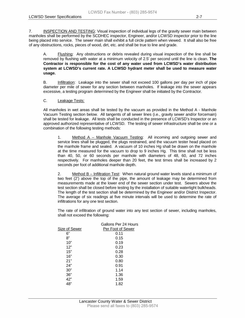
2. Method B – Infiltration Test: When natural ground water levels stand a minimum of two feet (2’) above the top of the pipe, the amount of leakage may be determined from measurements made at the lower end of the sewer section under test. Sewers above the test section shall be closed before testing by the installation of suitable watertight bulkheads. The length of the test section shall be determined by the Engineer and/or District Inspector. The average of six readings at five minute intervals will be used to determine the rate of infiltrations for any one test section. The rate of infiltration of ground water into any test section of sewer, including manholes, shall not exceed the following: Gallons Per 24 Hours Size of Sewer Per Foot of Sewer 6” 0.11 8” 0.15 10” 0.19 12” 0.23 15” 0.28 16” 0.30 21” 0.80 24” 0.91 30” 1.14 36” 1.36 42” 1.59 48” 1.82
LCWSD Fax Number - (803) 285-9574
Please send all faxes to (803) 285-9574
LCWSD Sewer Specifications 2-8
Lancaster County Water & Sewer District
3. Method C – Exfiltration Test: Where natural ground water levels do not stand two feet (2’) above the top of the pipe, the exfiltration test may be an approved method to be conducted on each section of sewer. The test shall be performed up to an average maximum hydrostatic head of ten feet (10’). The test shall be conducted in the following manner. The ends of the pipe in the test section shall be closed with suitable watertight bulkheads. Inserted into each bulkhead at the top of the sewer pipe shall be a 2-inch nipple with an elbow. At the upper end of the test section, a riser pipe shall be installed. The test section of the pipe shall be filled through the pipe connection in the lower bulkhead which shall be fitted with a tight valve, until all air is exhausted and until water overflows the riser pipe at the upper end. Water may be introduced into the pipe 24 hours prior to the test period to allow complete saturation. House service lines, if installed, shall also be fitted with suitable bulkheads having provisions for the release of air while the test section is being filled with water. During the test period, which shall extend over a period of 30 minutes, water shall be introduced into the riser pipe from measured containers at such intervals as are necessary to maintain the water level at the top of the riser pipe. The total volume of water added during the 30 minute test period shall not exceed the limits listed in Method B – Infiltration Test. 4. Low Pressure Air Test: At the Contractor’s and/or Engineer’s option, a low pressure air test may be conducted on each section of sewer after completion and before acceptance of the sewer infrastructure. Prior to air testing, the section of sewer between manholes shall be thoroughly cleaned and wetted. Immediately after cleaning or while the pipe is water soaked, the sewer shall be tested with low-pressure air. The Contractor and/or Engineer shall test the pipe between each manhole with the supervision of LCWSD’s inspector on site during the low-pressure air test. Air shall be slowly supplied to the plugged sewer section until internal air pressure reaches approximately 4.0 psi. After pressure is reached and the pressure allowed stabilizes (approximately two (2) to five (5) minutes, the pressure may be reduced to 3.5 psi before starting the tests. If a 1.0 psi drop does not occur within the test time, then the line has passed the test. If the pressure drops more than 1.0 psi during the test the line is presumed to have failed the test, and the Contractor and/or Engineer will be required to locate the failure, make necessary repairs, and retest the line. Minimum test time for various pipe sizes, in accordance with ASTM C828, as amended to date, is the following:
LCWSD Fax Number - (803) 285-9574
Please send all faxes to (803) 285-9574
LCWSD Sewer Specifications 2-9
Lancaster County Water & Sewer District
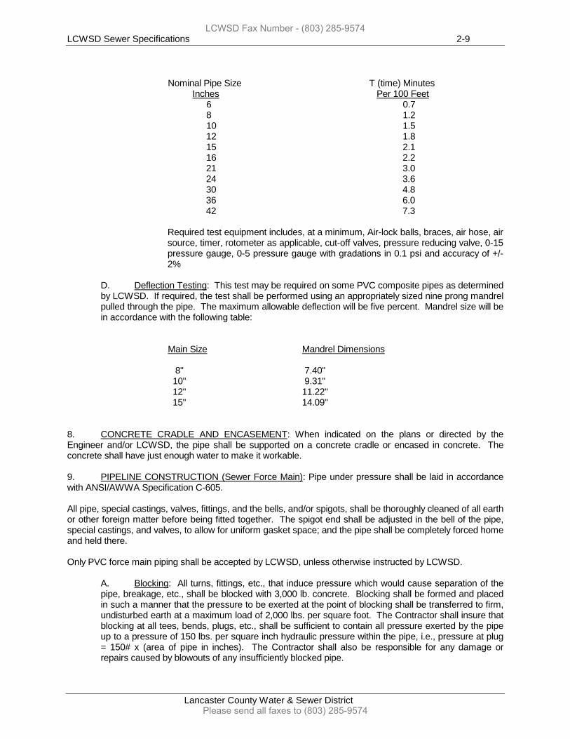
Nominal Pipe Size T (time) Minutes Inches Per 100 Feet
6 0.7 8 1.2 10 1.5 12 1.8 15 2.1 16 2.2 21 3.0 24 3.6 30 4.8 36 6.0 42 7.3
Required test equipment includes, at a minimum, Air-lock balls, braces, air hose, air source, timer, rotometer as applicable, cut-off valves, pressure reducing valve, 0-15 pressure gauge, 0-5 pressure gauge with gradations in 0.1 psi and accuracy of +/-2%
D. Deflection Testing: This test may be required on some PVC composite pipes as determined by LCWSD. If required, the test shall be performed using an appropriately sized nine prong mandrel pulled through the pipe. The maximum allowable deflection will be five percent. Mandrel size will be in accordance with the following table:
Main Size Mandrel Dimensions 8" 7.40" 10" 9.31" 12" 11.22" 15" 14.09" 8. CONCRETE CRADLE AND ENCASEMENT: When indicated on the plans or directed by the Engineer and/or LCWSD, the pipe shall be supported on a concrete cradle or encased in concrete. The concrete shall have just enough water to make it workable. 9. PIPELINE CONSTRUCTION (Sewer Force Main): Pipe under pressure shall be laid in accordance with ANSI/AWWA Specification C-605. All pipe, special castings, valves, fittings, and the bells, and/or spigots, shall be thoroughly cleaned of all earth or other foreign matter before being fitted together. The spigot end shall be adjusted in the bell of the pipe, special castings, and valves, to allow for uniform gasket space; and the pipe shall be completely forced home and held there. Only PVC force main piping shall be accepted by LCWSD, unless otherwise instructed by LCWSD.
A. Blocking: All turns, fittings, etc., that induce pressure which would cause separation of the pipe, breakage, etc., shall be blocked with 3,000 lb. concrete. Blocking shall be formed and placed in such a manner that the pressure to be exerted at the point of blocking shall be transferred to firm, undisturbed earth at a maximum load of 2,000 lbs. per square foot. The Contractor shall insure that blocking at all tees, bends, plugs, etc., shall be sufficient to contain all pressure exerted by the pipe up to a pressure of 150 lbs. per square inch hydraulic pressure within the pipe, i.e., pressure at plug = 150# x (area of pipe in inches). The Contractor shall also be responsible for any damage or repairs caused by blowouts of any insufficiently blocked pipe.
LCWSD Fax Number - (803) 285-9574
Please send all faxes to (803) 285-9574
LCWSD Sewer Specifications 2-10
Lancaster County Water & Sewer District
B. Testing: The Contractor will be required to set up a pump and test out each section of water line or sewage force main to a hydrostatic pressure of one hundred fifty (150) pounds per square inch or the rated pressure of the pipe whichever is less.
This test shall be sustained for not less than two hours, and as much longer as the Engineer may require to determine the tightness of the joints, or to detect any broken or otherwise defective material in the pipe lines. Leakage shall not exceed the amount determined by L = [(N)(D)(T)1/2] /1850 where L is leakage in gal/hr., N is number of joints, D is Inside Diameter of pipe in inches, and T is the Test Pressure in PSI. The Contractor shall remove and replace any defective material that shows evidence of leakage.
10. MANHOLE CONSTRUCTION: Excavation shall be made to the required depth and the foundation of the manhole shall be constructed as shown on the plans. Where existing manholes are to be reused, the Contractor shall make all connections thereto, as directed by the Engineer and/or LCWSD. Manholes (new and existing) shall be left clean and in good order and so kept until final acceptance of the work by LCWSD. Manhole tops shall be set at an elevation to be determined by the Engineer and LCWSD for each individual manhole. Any manhole that is built without securing this information from the Engineer and LCWSD, or not as ordered by the Engineer and LCWSD, that is found to be at an elevation too high or too low, shall be lowered or raised as ordered by LCWSD. If necessary to comply with the detail drawing, the manhole shall be required to be torn down to the beginning point of the draw-in and rebuilt from that point.
A. Pre-cast Concrete Manholes: Pre-cast concrete manholes shall be furnished and installed as specified within the Drawings and Details:
Excavation will be made to the required depth and the foundation on which the pre-cast manhole is to be set shall be approved by the Engineer and LCWSD approved plans. The excavation shall include the removal of obstructions and the removal of unstable materials unsuitable for a good foundation. The excavation shall allow for a minimum 6" thick bedding of crushed stone under the manhole base 7' square.
Pre-cast manholes shall consist of a monolithic pre-cast base section with built up 1:2 concrete mortar inverts. Pre-cast base sections shall be set at the proper invert elevations on a 6" thick base of crushed stone which is 7' square.
The barrel of the manhole shall be constructed from pre-cast, reinforced sections, stacked to form the manhole and manufactured according to the latest revision of ASTM C-478. The tapered section of the manhole shall be manufactured under the same specification and designed in a manner to suit the Engineer's requirements. Top slabs of manholes shall be designed to support street traffic and H-20 loadings. Pre-cast manhole sections shall be joined with mastic material to show both inside and outside. Inlet and outlet pipes are to be connected to the manholes by means of flexible connectors cast into the manhole section. Flexible connectors are to be manufactured of high quality rubber or synthetic rubber and all strap clamps or draw bolts are to be manufactured from stainless steel.
Pre-cast inverts are required in all pre-cast manholes.
11. CONNECTION TO EXISTING WORK: Connections to existing manholes and sewers shall be made
in such a manner that the work will conform to the requirements of new work. All OSHA Standards shall be taken into consideration by the Contractor for all connections to LCWSD’s existing sanitary sewer system. LCWSD is to charge contractors it’s current hot tapping fee charge to hot tap any LCWSD owned existing sewer force main line. Any existing manhole that will be receiving a proposed sewer force main into it shall be coated with interior coating which shall withstand
LCWSD Fax Number - (803) 285-9574
Please send all faxes to (803) 285-9574
LCWSD Sewer Specifications 2-11
Lancaster County Water & Sewer District
hydrogen sulfide bacterially corrosive environments down to a pH of 2. Lining shall be Raven 405, Sprayroq (Osborn Contracted Services, Inc.) or approved equal. Please refer to the Lining Specifications.
12. BORINGS:
A. Borings under Paved Roads and Highways: The minimum depth from the roadway surface to the top of the casing pipe at its closest point shall be 3'. When the casing pipe ends are below ground, they shall be protected from the entrance of foreign material. The depth of the bore must be confirmed by the current standards set forth by the South Carolina Department of Transportation (SCDOT). Those standards may be obtained by contacting their local SCDOT agency or via their website.
Contractors shall be required to provide shoring of boring pits and trenches more than 5' deep in accordance with the South Carolina Department of Transportation and Federal Occupation Health and Safety Administration.
B. Borings under Railroads: The depth from the base of the railway rail to the top of the casing at the closest point shall not be less than 5'. Also, there should not be less than 3' from the bottom of the side ditches to the top of the casing pipe. Where ends of casing pipe are below grade, provisions shall be taken to protect the ends against foreign material.
Contractors shall be required to shore all pits used for boring if it is over 5' deep in accordance with the local Railroad owner, the South Carolina Department of Transportation and Federal Occupational Health and Safety Administration. All bores underneath railroads must comply to the standards set forth by the affected railroad company. Prior to LCWSD approval of a railroad bore, the railroad company must review and issue a permit for the required railroad bore.
13. METHOD OF MEASUREMENT: The quantities to be paid for under this section shall be the actual number of feet of sanitary sewer pipe installed at varying depths and classes of pipe. The length shall be measured from the beginning of the pipe to the end of the line, including distances through intermediate manholes, except where cross lines are constructed, and in such cases, the distance through the manhole will be measured only. Manholes shall be measured by unit of the varying classifications of depth. The depth shall be measured from the invert of the effluent line to the top of the brick or block work. Where special drop manholes are constructed, payment shall be made on the basis of the unit price for drop manholes in various depth classifications.
LCWSD Fax Number - (803) 285-9574
Please send all faxes to (803) 285-9574

LCWSD Sewer Specifications 3-1
Lancaster County Water & Sewer District
SECTION 3
SANITARY SEWER CONSTRUCTION
GRAVITY MAINS AND FORCE MAINS
EARTHWORK
1. GENERAL: This section shall include all excavation, shoring, de-watering, filling, back-filling, and compacting as indicated on the drawings, and specified herein, and directed by LCWSD. Provisions of this section shall apply to all pipe work within streets or public rights-of-way, and any pipe work that will be added to LCWSD's sewer system. 2. CHARACTER OF EXCAVATION MATERIAL: Since soils vary widely within the project area, the Contractor shall satisfy himself as to the nature of material that will be encountered during the course of the project. All excavation shall be considered unclassified regardless of the material encountered. The Contractor shall follow all Federal OSHA requirements with all aspects of excavation. 3. EXISTING UNDERGROUND UTILITIES: The Contractor shall be responsible for locating all underground utilities and structures along the construction boundaries in order to avoid conflict and costly repair of damaged utilities. It shall be the responsibility of the Contractor to repair or replace any utility or structure if damaged during construction. 4. CONFLICTS: Where it is impossible to avoid conflict with existing utilities, the new construction shall be performed in a manner that will cause the least amount of disturbance to the existing facility. Any damage to existing facilities shall be repaired immediately according to the directions of the owner of such facilities, and it is the Contractor’s responsibility to reimburse any cost to repair the damage of existing facility, if damage was done by the Contractor. 5. TEMPORARY DRAINAGE: Pumping equipment shall be provided and employed to promptly remove any water that accumulates in the excavation. The area of excavation shall be limited to that which can properly be de-watered by the equipment in use. The excavation shall be maintained in a dry condition while construction is in progress. Surface water shall be diverted from the excavation by sloping the ground away from the ditch.
A. Disposal of Water: The water from the excavation shall be disposed of in such a manner that the natural drainage of the area shall not be disturbed. All gutters, drains, sewers, and culverts shall be kept clean for surface drainage.
6. SHORING: Shoring will be provided by the Contractor when the excavation will endanger existing structures, utilities, pavements and banks, and when necessary to protect workmen. The shoring shall be constructed of adequate size members and the arrangement of members shall be suitable to withstand the earth pressure expected. Shoring, sheeting, and bracing that is utilized above the invert of the pipe shall be removed carefully during the back-filling process in order to prevent caving that might displace the pipe from the correct line and grade. When and where directed by the Engineer, sheeting may be left in place in the backfill with adequate braces to provide lateral support. The Contractor shall follow all Federal Occupational Safety and Health Act requirements for any shoring. 7. EXCAVATION (General): Trenches shall be excavated by open cut to the line and grade given by the Engineer. Vertical cuts shall be used whenever possible, but in unstable soils, trenches may be sloped from the top of the excavation to a point 3.0 feet above the top of the pipe with the width of the trench from this depth to the bottom of the ditch governed by A below. The bottom 4" of the excavation shall be excavated by hand. Bell holes shall be excavated by hand to insure that the pipe is properly supported for its entire length. The Contractor shall follow all Federal Occupational Safety and Health Act requirements for any excavation.
LCWSD Fax Number - (803) 285-9574
Please send all faxes to (803) 285-9574
LCWSD Sewer Specifications 3-2
Lancaster County Water & Sewer District
A. Trench Width: The maximum width of the trench shall be 24" plus the outside diameter of the pipe. This width shall also apply to sloped trenches for the last 3' above the top of the proposed pipe.
B. Excavated Material: Material excavated from the ditch shall be placed at least two (2) linear feet back from the top of the ditch wall and in organized piles along the side of the trench. When it is necessary to stockpile excavated material, it shall be the Contractor's responsibility to secure the stockpile areas. No excavated material shall be placed on private property without the consent of the property owner.
C. All excavation shall be considered unclassified regardless of nature of material encountered.
D. Whenever the bottom of the trench is unstable or is comprised of rocks or other sharp debris, the Contractor shall remove such part as may be necessary and replace with suitable material from the surface to make a good foundation without extra compensation.
E. Under exceptional conditions where ground water and unstable soil are such that it is not possible to obtain a suitable foundation with material on the trench bank, the Engineer will determine the method to be followed and the Contractor will be compensated for extra foundation material delivered on the trench. On account of the difficulty in determining extra labor involved, no extra compensation will be allowed for placing it, but it will be held to be included in the unit price bid per linear foot of pipe.
F. Excavation for manholes and other appurtenances shall be sufficiently large enough to leave at least 12" clear between their outer surfaces and in the line of the excavation or supporting structure.
G. Any unauthorized excavation below the pipe or structure shall be filled with sand, gravel, or concrete, as approved by the LCWSD Inspector, at the expense of the Contractor.
H. Where sheathing or bracing is used, no extra compensation will be allowed, except where the Engineer directs that it be left in place. Payment reimbursement will be per LCWSD discretion and also approved by the Project Engineer. (Payment reimbursement pertains to projects by LCWSD).
8. BACKFILLING: Back-filling shall progress as rapidly as the pipe laying and testing permits. The trench shall be back-filled with approved material free from large clods or stones. The initial backfill shall be carefully placed on both sides of the pipe at the same time and thoroughly tamped around the barrel of the pipe until enough material has been placed to provide 2' of cover above the top of the pipe. The remainder of the backfill shall be placed in well compacted, one foot layers using approved mechanical tampers. In no case shall the backfill material be placed in unequal layers on one side of the pipe that might cause pipe displacement. In existing streets, roads or alleys and under sewer lift station buildings, the backfill shall be compacted to a density of 95% as determined by ASTM A-695 using approved mechanical tampers in 6" layers to the top of the trench. Contractor should provide at least two (2) borings with standard penetration tests and required lab testing to provide certification that backfill was placed in accordance with the LCWSD specifications. Tests to be performed adjacent to the existing building as near as possible for representative results for backfill placed on the site. In all other areas, the density shall be 90% as determined by ASTM A-695. When construction of sewer infrastructure is within County or State roads boundaries, then compaction and construction procedures must meet the standards and regulations set forth by the respective delegated authority. The top elevation of the trench shall be graded to the original grade that existed before excavation. In no case shall material such as old pavement, curbs, bricks or blocks be placed in the backfill. Compaction shall be attained by the use of mechanical tamps only. Heavy rollers, vehicles, or other equipment shall not be used for compacting pipeline and structure backfill nor allowed to cross over completed work except at points adjudged capable of adequately protecting the pipeline. Pneumatic tamps, gasoline ram type tamps or vibrating tamps with sheepsfoot rollers will be required to meet the specifications of “Mechanical Tamp”. The
LCWSD Fax Number - (803) 285-9574
Please send all faxes to (803) 285-9574
LCWSD Sewer Specifications 3-3
Lancaster County Water & Sewer District
Contractor is responsible for having all compaction tests carried out and delivering to LCWSD a copy of the tests results.
A. De-watering: De-watering, when required, shall be continued during construction including the pipe laying and the back-filling process. Adequate equipment shall be used and maintained by the Contractor to insure a dry trench.
B. Rock Cut: If rock is encountered in excavation, rock shall be removed to a depth of 8" below the bottom of the pipe. This 8" shall be refilled with select material.
C. Muck: Muck may be used in the backfill after at least 2.0 feet of approved material has been placed above the bell of the pipe. Muck shall not be used in the backfill in any street, road or alley. When it is encountered, approved backfill material shall be hauled in by the Contractor at the Contractor’s expense.
D. Sheeting: When sheeting is removed from the backfill, all cavities shall be properly filled and compacted.
9. EXCESS MATERIAL: Excess material and material that is suitable for backfill shall be disposed of at sites obtained by the Contractor at the Contractor’s expense. 10. BORROW: When the material excavated is not sufficient to meet the requirements for fill material, borrow shall be obtained by the Contractor at the Contractor’s expense. Borrow material shall be approved by LCWSD prior to placement. Borrow shall be paid for under this bid item for Select Material.
LCWSD Fax Number - (803) 285-9574
Please send all faxes to (803) 285-9574
LCWSD Sewer Specifications Page 4-1
Lancaster County Water & Sewer District
SECTION 4
SANITARY SEWER CONSTRUCTION GRAVITY MAINS AND FORCE MAINS
SITEWORK
1. GENERAL: This section includes the clearing and grubbing of all required construction areas with the disposal of materials, site preparation, and clean up as specified herein. 2. SITE PREPARATION:
A. Existing Facilities: The Contractor shall provide protection for all existing structures, buildings, and utilities against all construction activity. The Contractor shall protect and hold LCWSD harmless against damage and claims resulting from construction activities.
B. Streets and Highways: Effective barricades, caution/work zone signals, signage, and any other required safety precaution shall be provided, erected, and maintained by the Contractor for the protection of the work and the safety of the public. Barricades and obstructions that encroach on, or are adjacent to, public rights-of-way shall be properly lighted between the hours of sunset and sunrise. The Contractor shall conform to all South Carolina Department of Transportation laws and local laws and regulations in the use of streets and highways. The Contractor shall be responsible for all damages occurring due to neglect or failure to meet these requirements. When dictated by conditions that might endanger the public, a watchman shall be provided to fulfill the requirements stated herein.
C. Traffic Flow and Continuance of Services: The work shall be arranged in a manner that will cause a minimum of disturbance to vehicular and pedestrian traffic. Adequate egress and ingress to both private and public property shall be provided by the Contractor and/or Developer before and during all stages of construction. Developer shall receive all easements from private property owners prior to construction and transfer to LCWSD’s name after all construction has been completed at no cost to LCWSD. Without written approval from LCWSD, existing services shall not be interrupted by the construction work.
3. PRELIMINARY WORK:
A. Rights-of-Way: Adequate working space shall be cleared along the pipe lines and space shall be provided for control stakes and hubs. Only trees and permanent structures located within the right-of-way of new streets shall be removed only as directed.
B. Valuable Trees and Shrubs: When the construction work involves the removal of valuable trees and shrubs on existing public rights-of-way, the work shall be done in cooperation with the County or the South Carolina Department of Transportation.
C. Protection of Private Property: The Contractor shall provide protection for privately owned trees and shrubs bordering the right-of-way and shall take full responsibility for any damage that does occur.
4. CLEARING AND GRUBBING: Clearing and grubbing shall be performed in areas indicated and where required for construction. It shall include the complete removal and disposal of all brush, weed, timber, stumps, rubbish, and all other obstructions. All such material shall be removed to a depth of at least one foot below finished grade. In clearing and grubbing areas where excavation is done, all timber, roots, or stumps removed that are exposed by said excavation shall be removed to a depth of one foot below the excavated surface.
LCWSD Fax Number - (803) 285-9574
Please send all faxes to (803) 285-9574
LCWSD Sewer Specifications Page 4-2
Lancaster County Water & Sewer District
5. DISPOSAL OF CLEARED AND GRUBBED MATERIAL: All refuse from the clearing and grubbing operation shall be disposed of either by burning (upon the appropriate approvals and receiving the required permits) or removal to an approved dump area. The Contractor shall obtain a burning permit from any required local or state agency before any burning is started. Burning, if approved, shall be done in such a manner that it does not create hazards such as damage to existing structures, trees and vegetation, interference with traffic and construction in progress. All disposal by burning shall be kept under constant supervision until all fires have been extinguished and all burning shall comply with all state and local laws relative to the building of fires. 6. PAVEMENT REMOVAL AND REPLACEMENT:
A. Removal: When pipe is to be laid in existing paved streets, the pavement shall be cut to true and neat lines as directed by LCWSD and/or South Carolina Department of Transportation Representative. Power driven cutting saws are preferred; pavement breakers driven by air compressors are acceptable if approved by LCWSD. All broken pavement shall be removed before trenching is started.
B. Replacement: The pipe trench shall be back-filled with granular select material to within 10" of the pavement surface. The trench shall then be filled with ABC stone to the surface and sufficiently compacted. For pavement replacement for South Carolina Department of Transportation maintained roads must be filled with a flowable fill type material. Please refer to the Pavement Removal/Replacement Details in the Construction Drawings for an explanation of fill compaction and lifts. The stone fill shall be maintained in a workmanlike manner until the asphalt surface has been replaced. The edges of the asphalt shall be neatly trimmed to a new face and mopped with asphalt cement. The asphalt surface shall be placed and thoroughly rolled to a smooth, dense surface true to adjacent areas of the street. The asphalt surface course shall consist of Type I-2 bituminous concrete surface course in accordance with South Carolina Department of Transportation Specifications.
Cut areas shall be maintained by the Contractor in a safe, passable condition until paved. Should the area create a dusty condition, the Contractor shall remedy this condition by the use of water or calcium chloride. Special care shall be given to the areas cut in traffic lanes and intersections by placing crushed stone and maintaining in a smooth condition at the Contractor's expense. If a cut area is filled with flowable fill, the traffic must be maintained until the flowable fill sets; therefore, use of steel plates or other SCDOT approved measures must be used until the road is properly paved.
C. Sidewalk, Driveway and Curb and Gutter Replacement: Existing sidewalks and paved driveways, including curb and gutters removed, disturbed or destroyed by construction, shall be replaced or repaired. The finished work shall be equal or greater in all respects to the original condition.
D. State Highway Crossing: All construction related to state highway crossing shall be in full compliance with all requirements of the permit and to the satisfaction of the South Carolina Department of Transportation.
7. SEDIMENTATION AND EROSION CONTROL: The Contractor is instructed to control sedimentation runoff by methods approved by the Engineer, the Storm Water Management Division of SC DHEC, and the most recent and amended edition of the S.C. Stormwater Management and Sediment Control Handbook for Land Disturbing Activities as published by SC DHEC. LCWSD shall have a copy of the approved Storm Water Permit prior to the Contractor beginning construction. At project completion, it is the responsibility of the Contractor to stabilize the sewer easement/right-of-ways with permanent grassing or the permanent stabilization measure stated within the permit and/or Construction Drawings. The Contractor shall remove all temporary erosion control measures (i.e., silt fence, check dams, etc.) once the easement/right-of-way has been permanently stabilized. Project is not considered complete
LCWSD Fax Number - (803) 285-9574
Please send all faxes to (803) 285-9574
LCWSD Sewer Specifications Page 4-3
Lancaster County Water & Sewer District
until the construction area is permanently stabilized and all temporary erosion control measures have been removed.
LCWSD Fax Number - (803) 285-9574
Please send all faxes to (803) 285-9574
LCWSD Sewer Specifications Page 5-1
Lancaster County Water & Sewer District
SECTION 5
SANITARY SEWER CONSTRUCTION GRAVITY MAINS AND FORCE MAINS
BORING UNDER HIGHWAYS AND RAILROADS
1. SCOPE: This section shall include furnishing all labor, tools, equipment and other incidentals required to bore casing pipe under highways or railroads. In addition to Section 5, Boring Under Highways and Railroads, please refer to Section 1, Casing Pipe on page 1-8 2. BORINGS: Procedures for boring shall be in accordance with all of the most recent boring requirements set forth by the South Carolina Department of Transportation (SCDOT) and/or Lancaster County, the best accepted methods of construction, as shown on the plans, and as detailed in these specifications.
A. Boring Under Highways: Lines installed under highways shall be bored as shown on the detail descriptions contained in these specifications. Casings will be installed of the type, size, and thickness as specified herein or on the detail drawings. The Contractor shall be responsible for notifying the South Carolina Department of Transportation as required prior to any contemplated work and for securing any required permits for performing the work. All work shall be accomplished under the supervision of the Engineer, LCWSD, and the District Engineer of the South Carolina Department of Transportation or an authorized representative.
1. Carrier Pipe: Carrier pipe used under highways shall be of an approved material and installed to the satisfaction of the District Engineer of the South Carolina Department of Transportation.
2. Casing Pipe: The inside diameter of the casing pipe shall not be less than 2" greater than the largest outside diameter of the joints and couplings for carrier pipe less than 6" O.D., and 4" greater for carrier pipe 6" and larger. Casing pipe shall, in all cases, be great enough in diameter to easily remove carrier pipe and casing spiders without disturbing the casing pipe. Casing spiders shall be stainless steel in material, unless otherwise approved by LCWSD, and shall be installed to keep carrier piping center inside of the casing pipe.
(a) Pipe Size 8" & Smaller: Schedule 40 wrought steel or wrought iron pipe having a wall thickness as shown below may be used for casing pipe 8" and smaller.
LCWSD Fax Number - (803) 285-9574
Please send all faxes to (803) 285-9574
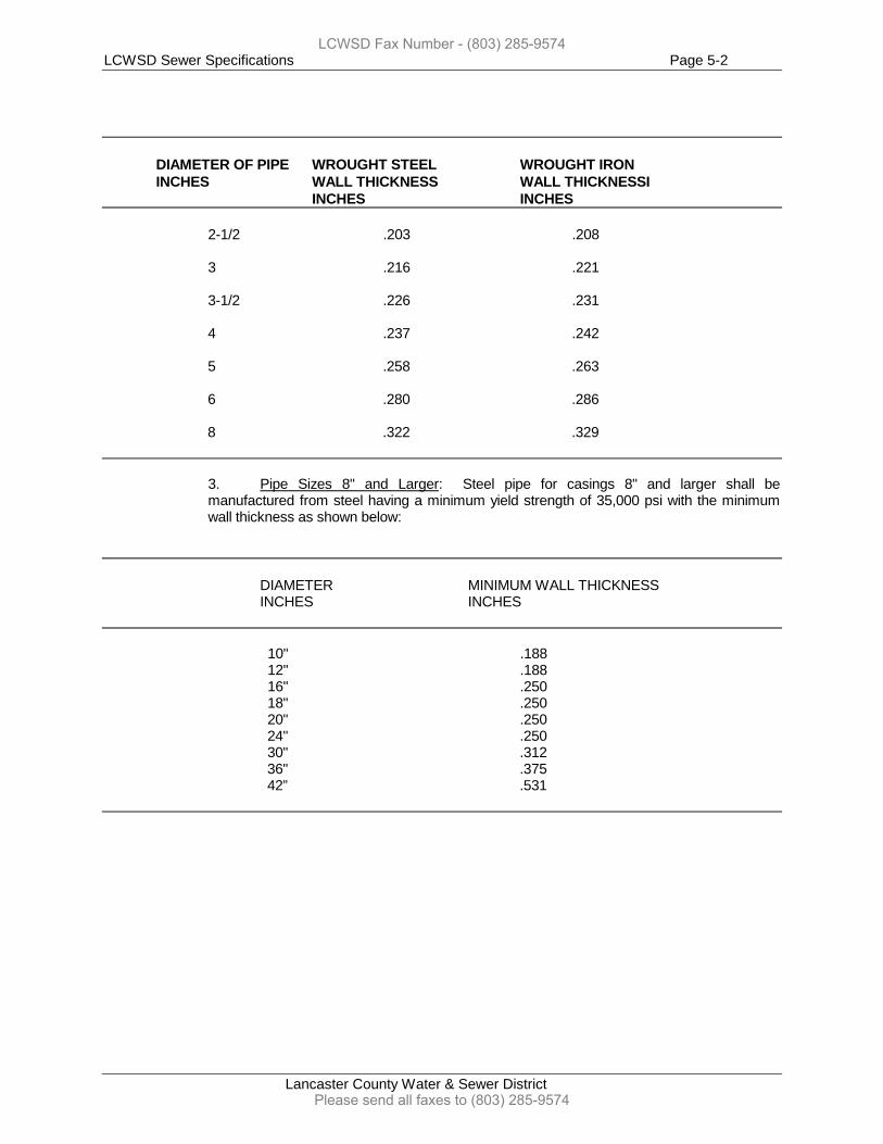
LCWSD Sewer Specifications Page 5-2
Lancaster County Water & Sewer District
DIAMETER OF PIPE WROUGHT STEEL WROUGHT IRON
INCHES WALL THICKNESS WALL THICKNESSI INCHES INCHES
2-1/2 .203 .208 3 .216 .221 3-1/2 .226 .231 4 .237 .242 5 .258 .263 6 .280 .286 8 .322 .329
3. Pipe Sizes 8" and Larger: Steel pipe for casings 8" and larger shall be manufactured from steel having a minimum yield strength of 35,000 psi with the minimum wall thickness as shown below:
DIAMETER MINIMUM WALL THICKNESS INCHES INCHES 10" .188 12" .188 16" .250 18" .250 20" .250 24" .250 30" .312 36" .375
42” .531
LCWSD Fax Number - (803) 285-9574
Please send all faxes to (803) 285-9574
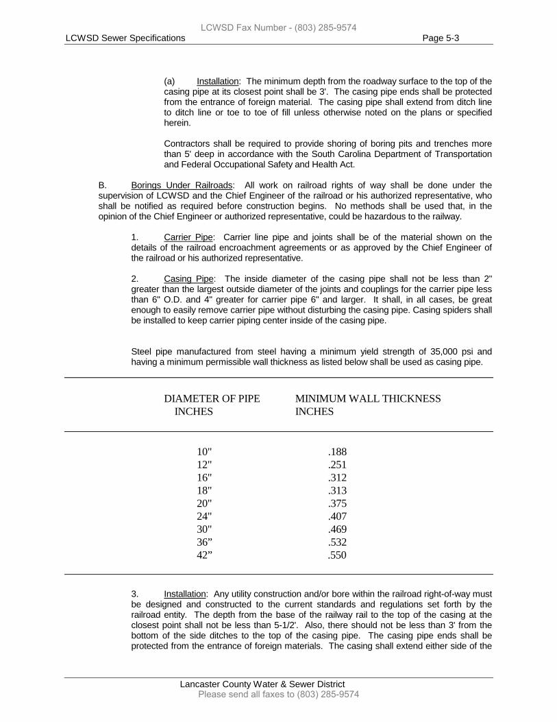
LCWSD Sewer Specifications Page 5-3
Lancaster County Water & Sewer District
(a) Installation: The minimum depth from the roadway surface to the top of the casing pipe at its closest point shall be 3'. The casing pipe ends shall be protected from the entrance of foreign material. The casing pipe shall extend from ditch line to ditch line or toe to toe of fill unless otherwise noted on the plans or specified herein.
Contractors shall be required to provide shoring of boring pits and trenches more than 5' deep in accordance with the South Carolina Department of Transportation and Federal Occupational Safety and Health Act.
B. Borings Under Railroads: All work on railroad rights of way shall be done under the supervision of LCWSD and the Chief Engineer of the railroad or his authorized representative, who shall be notified as required before construction begins. No methods shall be used that, in the opinion of the Chief Engineer or authorized representative, could be hazardous to the railway.
1. Carrier Pipe: Carrier line pipe and joints shall be of the material shown on the details of the railroad encroachment agreements or as approved by the Chief Engineer of the railroad or his authorized representative.
2. Casing Pipe: The inside diameter of the casing pipe shall not be less than 2" greater than the largest outside diameter of the joints and couplings for the carrier pipe less than 6" O.D. and 4" greater for carrier pipe 6" and larger. It shall, in all cases, be great enough to easily remove carrier pipe without disturbing the casing pipe. Casing spiders shall be installed to keep carrier piping center inside of the casing pipe.
Steel pipe manufactured from steel having a minimum yield strength of 35,000 psi and having a minimum permissible wall thickness as listed below shall be used as casing pipe.
DIAMETER OF PIPE MINIMUM WALL THICKNESS INCHES INCHES 10" .188 12" .251 16" .312 18" .313 20" .375 24" .407 30" .469 36” .532 42” .550
3. Installation: Any utility construction and/or bore within the railroad right-of-way must be designed and constructed to the current standards and regulations set forth by the railroad entity. The depth from the base of the railway rail to the top of the casing at the closest point shall not be less than 5-1/2'. Also, there should not be less than 3' from the bottom of the side ditches to the top of the casing pipe. The casing pipe ends shall be protected from the entrance of foreign materials. The casing shall extend either side of the
LCWSD Fax Number - (803) 285-9574
Please send all faxes to (803) 285-9574
LCWSD Sewer Specifications Page 5-4
Lancaster County Water & Sewer District
centerline of the railroad track to outside of the railroad right-of-way. Contractors shall be required to shore all pits used for boring if it is over 5' deep as required by the railway, the South Carolina Department of Transportation, and the Federal Occupational Safety and Health Act. The railroad permit must be submitted to LCWSD prior to the Contractor beginning any utility construction that involves any construction under or within the railroad right-of-way. 4. Work in the railroad rights-of-way: Permits for all construction within the rights-of-way of railroads shall be obtained by the Contractor and/or Design Engineer and shall be approved by the railroad before commencing work in these areas. All construction of utility lines shall be installed with full compliance, including any special conditions, set forth in the approved permit, and to the approved satisfaction and inspections of the Railroad Company, including the carrier pipe and encasement. The Contractor shall notify the railway in advance prior to commencing in construction. The Contractor is required to provide any and all required warning and protective measures and special provisions required by the Railroad Company and permit.
3. METHOD OF MEASUREMENT: Bores shall be measured in linear feet from end to end of casing pipe installed and accepted. This item shall include casing pipe and other materials, tools, equipment, labor and incidentals required to bore and install casing as shown on the details and as directed by the highway or railroad district engineer and/or resident engineer and/or LCWSD.
LCWSD Fax Number - (803) 285-9574
Please send all faxes to (803) 285-9574
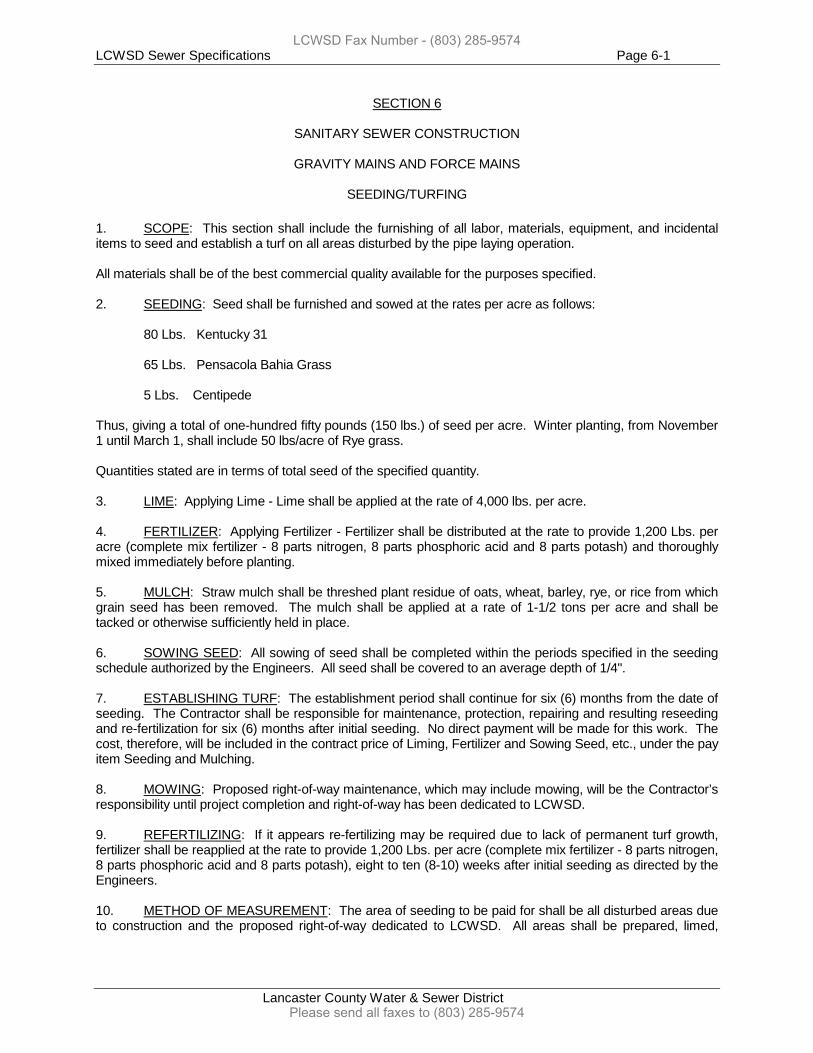
LCWSD Sewer Specifications Page 6-1
Lancaster County Water & Sewer District
SECTION 6
SANITARY SEWER CONSTRUCTION
GRAVITY MAINS AND FORCE MAINS
SEEDING/TURFING
1. SCOPE: This section shall include the furnishing of all labor, materials, equipment, and incidental items to seed and establish a turf on all areas disturbed by the pipe laying operation. All materials shall be of the best commercial quality available for the purposes specified. 2. SEEDING: Seed shall be furnished and sowed at the rates per acre as follows: 80 Lbs. Kentucky 31 65 Lbs. Pensacola Bahia Grass 5 Lbs. Centipede Thus, giving a total of one-hundred fifty pounds (150 lbs.) of seed per acre. Winter planting, from November 1 until March 1, shall include 50 lbs/acre of Rye grass. Quantities stated are in terms of total seed of the specified quantity. 3. LIME: Applying Lime - Lime shall be applied at the rate of 4,000 lbs. per acre. 4. FERTILIZER: Applying Fertilizer - Fertilizer shall be distributed at the rate to provide 1,200 Lbs. per acre (complete mix fertilizer - 8 parts nitrogen, 8 parts phosphoric acid and 8 parts potash) and thoroughly mixed immediately before planting. 5. MULCH: Straw mulch shall be threshed plant residue of oats, wheat, barley, rye, or rice from which grain seed has been removed. The mulch shall be applied at a rate of 1-1/2 tons per acre and shall be tacked or otherwise sufficiently held in place. 6. SOWING SEED: All sowing of seed shall be completed within the periods specified in the seeding schedule authorized by the Engineers. All seed shall be covered to an average depth of 1/4". 7. ESTABLISHING TURF: The establishment period shall continue for six (6) months from the date of seeding. The Contractor shall be responsible for maintenance, protection, repairing and resulting reseeding and re-fertilization for six (6) months after initial seeding. No direct payment will be made for this work. The cost, therefore, will be included in the contract price of Liming, Fertilizer and Sowing Seed, etc., under the pay item Seeding and Mulching. 8. MOWING: Proposed right-of-way maintenance, which may include mowing, will be the Contractor’s responsibility until project completion and right-of-way has been dedicated to LCWSD. 9. REFERTILIZING: If it appears re-fertilizing may be required due to lack of permanent turf growth, fertilizer shall be reapplied at the rate to provide 1,200 Lbs. per acre (complete mix fertilizer - 8 parts nitrogen, 8 parts phosphoric acid and 8 parts potash), eight to ten (8-10) weeks after initial seeding as directed by the Engineers. 10. METHOD OF MEASUREMENT: The area of seeding to be paid for shall be all disturbed areas due to construction and the proposed right-of-way dedicated to LCWSD. All areas shall be prepared, limed,
LCWSD Fax Number - (803) 285-9574
Please send all faxes to (803) 285-9574
LCWSD Sewer Specifications Page 6-2
Lancaster County Water & Sewer District
fertilized, seeded, re-fertilized, re-seeded, repaired, turf established and accepted as directed by the Engineer, LCWSD, and/or the Developer.
LCWSD Fax Number - (803) 285-9574
Please send all faxes to (803) 285-9574
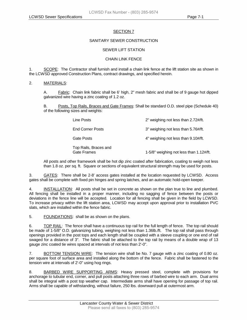
LCWSD Sewer Specifications Page 7-1
Lancaster County Water & Sewer District
SECTION 7
SANITARY SEWER CONSTRUCTION SEWER LIFT STATION
CHAIN LINK FENCE
1. SCOPE: The Contractor shall furnish and install a chain link fence at the lift station site as shown in the LCWSD approved Construction Plans, contract drawings, and specified herein. 2. MATERIALS:
A. Fabric: Chain link fabric shall be 6’ high, 2" mesh fabric and shall be of 9 gauge hot dipped galvanized wire having a zinc coating of 1.2 oz.
B. Posts, Top Rails, Braces and Gate Frames: Shall be standard O.D. steel pipe (Schedule 40) of the following sizes and weights:
Line Posts 2" weighing not less than 2.72#/ft. End Corner Posts 3" weighing not less than 5.76#/ft. Gate Posts 4" weighing not less than 9.10#/ft. Top Rails, Braces and Gate Frames 1-5/8" weighing not less than 1.12#/ft.
All posts and other framework shall be hot dip zinc coated after fabrication, coating to weigh not less than 1.8 oz. per sq. ft. Square or sections of equivalent structural strength may be used for posts.
3. GATES: There shall be 2-8’ access gates installed at the location requested by LCWSD. Access gates shall be complete with fixed pin hinges and spring latches, and an automatic hold-open keeper. 4. INSTALLATION: All posts shall be set in concrete as shown on the plan true to line and plumbed. All fencing shall be installed in a proper manner, including no sagging of fence between the posts or deviations in the fence line will be accepted. Location for all fencing shall be given in the field by LCWSD. To increase privacy within the lift station area, LCWSD may accept upon approval prior to installation PVC slats, which are installed within the fence fabric. 5. FOUNDATIONS: shall be as shown on the plans. 6. TOP RAIL: The fence shall have a continuous top rail for the full length of fence. The top rail should be made of 1-5/8" O.D. galvanizing tubing, weighing not less than 1.36lb./ft. The top rail shall pass through openings provided in the post tops and each length shall be coupled with a sleeve coupling or one end of rail swaged for a distance of 3". The fabric shall be attached to the top rail by means of a double wrap of 13 gauge zinc coated tie wires spaced at intervals of not less than 2'-0". 7. BOTTOM TENSION WIRE: The tension wire shall be No. 7 gauge with a zinc coating of 0.80 oz. per square foot of surface area and installed along the bottom of the fence. Fabric shall be fastened to the tension wire at intervals of 2'-0" using hog rings. 8. BARBED WIRE SUPPORTING ARMS: Heavy pressed steel, complete with provisions for anchorage to tubular end, corner, and pull posts attaching three rows of barbed wire to each arm. Dual arms shall be integral with a post top weather cap. Intermediate arms shall have opening for passage of top rail. Arms shall be capable of withstanding, without failure, 250 lbs. downward pull at outermost arm.
LCWSD Fax Number - (803) 285-9574
Please send all faxes to (803) 285-9574
LCWSD Sewer Specifications Page 7-2
Lancaster County Water & Sewer District
9. BARBED WIRE: Three strands, 12-1/2 gauge wire with 14 gauge 4 point barbs spaced approximately 5" O.C. Wire shall have a zinc coating of 0.8 oz. as per ASTM A-491, Class 2, as amended to date.
LCWSD Fax Number - (803) 285-9574
Please send all faxes to (803) 285-9574
LCWSD Sewer Specifications Page 8-1
Lancaster County Water & Sewer District
SECTION 8
SANITARY SEWER CONSTRUCTION
SEWER LIFT STATION
1. SCOPE OF WORK: The Contractor shall furnish all labor, materials, tools, equipment and performance of all work necessary to furnish and install the sewer lift station(s) as herein described and noted on the detailed plans. Any deviations from the proposed design and specifications shall be pre-approved by LCWSD. Major items of construction shall include, but not limited to, the following: Wet Well w/ Anti-Flotation Collar
2 - Submersible Non-Clog Sewer Pumps, Motors and Accessories (unless otherwise approved)
Complete Stainless Steel Lift-Out and Stainless Steel Guide Rail Assembly Complete Flanged Discharge Piping Fittings 2 - Check Valves 2 - Gate Valves Aluminum Access Doors for wet well and valve vault as noted Duplex Central Control Panel and 5 Level Controls (low water, pump off, lead, lag, high water) PVC Vent System A minimum 4' x 4' x 5' Pre-cast Valve Vault LCWSD supplied (at the developer’s/contractor’s expense) telemetry system A District approved standby generator set (see Special Provisions Section) The above noted items are for reference only and should not be considered inclusive of all materials necessary for the construction of the lift station. The Contractor is responsible for providing all incidentals necessary to complete the station as shown on the detailed plans and further specified herein. The Contractor shall also be responsible for submitting three (3) copies of all submittals of all lift station infrastructure for the proposed lift station according to the requirements of this section. 2. PUMPS: The Contractor shall be responsible for providing two (2) sewer submersible (unless otherwise specified) pumps capable of operating with 3 Phase power, unless approved otherwise, and meeting the following minimum design conditions capable of remaining within 4-6 pumping cycles per hour: Design Capacity Total Dynamic Head (Range) Maximum Speed Minimum Design Efficiency Discharge Size Minimum Solids Capability Shut Off Head Minimum Driver Horsepower Motor Requirements Pump Type, Brand, and Model Potential Acceptable Pump Manufacturers
A. Submersible Non-Clog Sewage Pumps: The pumps are to be designed and constructed to pumping sewer, heavy sludge and other fibrous materials without injurious damage during operation. The lifting cover, stator housing, volute casing, and impeller shall be constructed of ASTM 48, Class 30 gray cast iron. The volute will be fitted with ANSI 125 lb. flanges and tested to Hydraulic Institute
LCWSD Fax Number - (803) 285-9574
Please send all faxes to (803) 285-9574
LCWSD Sewer Specifications Page 8-2
Lancaster County Water & Sewer District
standards at 150% of shut-off head. The interfaces between the major castings shall be machined and fitted with buna O-rings. All nuts, bolts, chains, washers and other fastening devices inside of wet well shall be constructed of 316 stainless steel. The pump manufacturers Barnes, EMU, and Hydromatic are the only approved pump manufacturers for LCWSD unless other manufacturers are approved by LCWSD during the design of the station.
Depending on design point and pump manufacturer recommendations, the impeller shall be one (1) vane or two (2) vane enclosed non-clog design with pump out vanes on the back side to prevent grit and other material from collecting in the seal area. The impeller shall be of the one-piece, single suction, radial flow design with well-rounded leading edges and thick hydrofoil shape with large openings to prevent the accumulation of solids and stringy material through the impeller.
Each pump shall be provided with a tandem mechanical rotation shaft seal system. The mechanical seal chamber will be oil filled and equipped with a moisture detection device wired internally to the control cable. Each seal shall be held in contact by its own spring system and require neither maintenance nor adjustment, but shall be easily inspected and replaceable. Per manufacturer recommendations, the lower seal shall be manufactured of Tungsten Carbide and include a protective cup to prevent solids or stringy material from lodging in the seal spring, and the upper seal will be carbon ceramic. (All faces of EMU pumps use Silicon Carbide.)
The pump and motor shaft will be of Series 400 stainless steel with a Brinnell hardness of 200. The shaft shall be designed such that the diameter of the shaft is based on the pump selection with a maximum shaft deflection due to axial and radial thrust loads of 0.16 mm. The shaft is supported by lower (single row or double row per manufacturer specifications) thrust bearing and single row upper radial ball bearings with an L-10 life of 50,000 hours - minimum.
The sliding bracket assembly shall be attached to the pumping unit, constructed so that when lowered to the discharge base/elbow, the knifing action of the vertical metal to metal seal provides a self-cleaning, non-clogging, UL listed, non-sparking assembly.
Seal of the pump at the discharge flange will be accomplished by simple downward linear motion of the pump with the entire weight of the pump guided to and pressing against connection, no part of the pump shall bear directly on the sump floor and no rotary motion of the pump is required for sealing. The system shall include a stainless steel lift chain for raising and lowering each pump. Each stainless steel lift cable or chain shall be connected to the bottom frame of the access hatch.
Motor shall be filled with a FDA approved cooling oil. The oil shall be circulated via the centrifugal rotation of the shaft and rotor. The power cable shall be isolated by means of an O-ring terminal board for oil-filled motors and O-ring seal and two epoxy potted areas for air-filled motors. Motors shall meet the design criteria scheduled on the drawings. The code letter of the motor shall be determined at motor selection, but is typically a code letter “G” or less. Locked rotor kilovolt amperes shall not exceed 6.29 per horsepower and shall be explosion proof. The amperes will be dependent upon pump selection. Provide motor with thermal sensors, normally closed contacts, wired in series with starter overload contacts. All pump motors 40 Hp and above (including variable speed pumps) shall have a soft start starter for slow start processes. Some applications may warrant a variable frequency drive (VFD) system to maximize the present and future flow conditions.
Pump and control cables shall be UL listed "Water Resistant", properly sized and of proper length to suit the installation. Each cable shall be provided with a green equipment grounding conductor, sized as required, to meet code. The cable support grips for the cables must be tin coated bronze or zinc.
Cable entry system shall consist of three (3) separate seals. A rubber grommet that seals both cable jackets shall be clamped onto cord by end holding cap. An "O" ring shall seal cap to bottom half of cord cap. Both cables shall have individual conductors stripped and potted into motor if the cable
LCWSD Fax Number - (803) 285-9574
Please send all faxes to (803) 285-9574
LCWSD Sewer Specifications Page 8-3
Lancaster County Water & Sewer District
jacket becomes damaged. Cords shall withstand a pull of 150 pounds without loosening or losing integrity.
B. Submersible Grinder Sewage Pumps: The pumps shall be of the submersible centrifugal type with recessed pumping impeller, integrally built-in grinder unit, and submersible motor. Grinder shall be capable of macerating materials in normal domestic sewage, including items used in maintaining normal sanitary hygiene such as: disposable diapers, sanitary napkins, rubber and the like into a fine slurry. Pump shall not be intended to handle abrasive material or sewer containing large excessive amounts of sand, grit, or other stone-like compositions. Contractor shall include all labor, materials, equipment incidentals and ancillary components to make a complete lift station system.
Pump motor shall be of the totally enclosed, submersible, squirrel cage, induction type. Single phase motors (achieved by the use of a VFD or an Add-a-Phase) shall be of the capacitor start, capacitor run, NEMA Class B type.
Stator windings shall be of the open type with NEMA Class B insulation good for 130o C (266o F). Windings shall operate in clean high dielectric oil that lubricates bearings and seals and transfers heat from windings to outer shell. Stators will be bolted in place for proper alignment. Air-filled motors which do not have superior heat dissipating capabilities of oil filled motors shall not be considered equal.
Motor shall have two bearings. Upper and lower ball bearings shall support motor rotor. Upper ball bearings shall take thrust loads, lower ball bearing shall take radial loads, and lower sleeve bushing shall take all radial shock loading due to grinding action. Ball bearings shall be designed for a minimum L10 life of 50,000 hours.
A heat sensor thermostat shall be imbedded in top of windings and be connected in series with the motor starter coil control box to stop motor if temperature rises in motor to over 266o F for any reason. Thermostat is to reset automatically when temperature drops to a safe limit. Three-phase motors to have two (2) heat sensor thermostats attached to adjacent windings.
The common motor, pump and grinder shaft shall be at least 416 stainless steel. Pump impeller and grinding impeller shall thread onto shaft.
Motor shall be protected by two (2) mechanical shaft seals mounted in tandem with an oil-filled chamber between the seals for lubricating seal faces and providing buffer zone to protect motor in event of first seal leakage. Upper seal face shall be of carbon and ceramic lapped to a flatness tolerance of one light band. The lower seal shall be manufactured of Tungsten Carbide and include a protective cup to prevent solids or stringy material from lodging in the seal spring. Metal parts and springs for seals shall be stainless steel, unless otherwise approved by LCWSD.
Pump shall be of the recessed type to provide an open unobstructed passage through the volute. Impeller shall be of 85-5-5-5 bronze or ASTM A48 Class 35 B Cast Iron and shall thread onto shaft. Enclosed or semi-open pump impellers which might become obstructed during grinding or add excessive radial loads shall not be considered as equal. The backside of the impeller shall have grit and other material from collecting in the seal area.
The combination centrifugal impeller and grinder unit shall be attached to the common motor and pump shaft made of 416 stainless steel. The grinder unit shall be on the suction side of the pump impeller and discharge directly into the impeller inlet leaving no exposed shaft to permit packing of ground solids. The grinder shall consist of two (2) stages. The cutting action of the second stage shall be perpendicular to the plane of the first cut for better control of the particle size. The grinder shall be capable of grinding all materials found in normal domestic sewage, including plastics, rubber, sanitary napkins, disposable diapers, and wooden articles into a finely ground slurry with a
LCWSD Fax Number - (803) 285-9574
Please send all faxes to (803) 285-9574
LCWSD Sewer Specifications Page 8-4
Lancaster County Water & Sewer District
particle dimension no greater than ¼”. Both stationary and rotation cutters shall be made of 440C stainless steel hardened to Rockwell 60C and ground to close tolerance. The upper (axial) cutter and stationary cutter ring shall be reversible to provide new cutting edges to double the life of the cutter. The stationary cutter ring shall be a slip fit into the suction opening of the volute and held in place by three (3) 300-series stainless steel screws and retaining ring. The lower (radial) cutter shall macerate the solids against the I.D. of the cutter ring and extrude them through the slots of the cutter ring. The upper (axial) cutter shall cut off the extrusions, as they emerge from the slots of the cutter ring to eliminate any roping effect, which may occur in single stage cutting action. The upper (axial) cutter shall fit over the hub of the impeller and the lower (radial) cutter shall slip fit and be secured by means of peg and hole and rotate simultaneously with the rotation of the shaft and impeller. A 300 series stainless steel countersunk washer in conjunction shall lock the grinding mechanism to the shaft with a 300 series stainless steel flat head cap screw threaded into the end of the shaft. All castings shall be of high tensile strength cast iron. Castings shall be treated with phosphate and chromic rinse prior to painting. Castings shall be painted with a high quality, lead free, alkyd enamel finish.
All fasteners shall be of 300 series stainless steel. All grinder pumps shall be equipped with appropriately sized stainless steel cable for installation and removal purposes.
Motor power cord shall be 10/4 or 8/4 SOW/SOWA 4 conductor of proper length to suit installation. Motor control cords to be 18/5 SOW/SOWA 5 conductor of proper length to suit installation. Each cable shall be provided with a green ground wire to be grounded in accordance with local and national electric codes. Each pump shall have 90 rated wiring.
Cable entry system shall consist of three (3) separate seals. A rubber grommet that seals both cable jackets shall be clamped onto cord by end holding cap. An "O" ring shall seal end cap to bottom half of cord cap. Both cables shall have individual conductors stripped and potted into motor if the cable jacket become damaged. Cords shall withstand a pull of 150 pounds without loosening or losing integrity. The end holding cap shall have female threaded tapping for 2" conduit.
Lift-Out Rail System shall consist of a check valve and seal fitting that mounts horizontally into a stationary discharge pipe. A simple downward motion shall connect pump and check valve and seal fitting to the stationary discharge casting. Check valve and seal fitting shall seal with two (2) “O” rings and a tapered rubber seal ring into funnel of discharge case. Check valve flapper shall be spring loaded to prevent water hammer slam. Discharge casting shall be furnished with right or left hand discharge pipe connections for duplex systems. Discharge pipe tapping shall be 3” NPT female for standard pipe. Valve casting and discharge casting shall be painted with a high quality, lead free, alkyd enamel finish.
An upper guide plate shall be provided to prevent pump and seal fitting from rising on rails. Guide rails shall be 1-1/4” stainless steel piping. Hold down pipe shall be ½” stainless steel pipe. Rail support shall be adjustable so that perfect vertical alignment of the rails can be obtained.
3. CONCRETE STRUCTURES: The proposed wet well and valve vault (where specified) must be in
accordance with the detailed drawings and following specifications.
A. Wet Well Structure: The wet well structure shall consist of one concrete monolithically cast base section with an invert and a minimum 6" long base slab extension for counter floatation. The wet well risers/top sections shall have a minimum wall thickness of 7". Both top slab and bottom shall have a minimum thickness of 7". All openings in wet well sections shall be cast-in with the exception of the influent pipe opening which shall be cored in the wall. The latest revision of the following standards shall apply: ASTM C890-73, ASTM C891-78, and ASTM C913-79. The wet well
LCWSD Fax Number - (803) 285-9574
Please send all faxes to (803) 285-9574
LCWSD Sewer Specifications Page 8-5
Lancaster County Water & Sewer District
shall have a lockable aluminum hatch cast into the top with an aluminum access ladder for access, if applicable. Access to the interior of the wet well shall be facilitated by cast in place steps by the wet well manufacturer. LCWSD, at its sole discretion, may require the wet well to have a LCWSD approved interior lining in place to protect against corrosion and deterioration caused by H2S gases.
B. Valve Vault: The valve vault, where required, shall be made of pre-cast concrete and manufactured of the dimensions noted on the plans and specified herein. The vault shall be drained to the wet well by using a PVC drain pipe and PVC check valve assembly not glued for future replacement purposes. Access to the vault will be facilitated by use of cast-in-place step or aluminum access ladder.
C. Concrete: Cement shall be Type II, having a maximum Tricalcium Illuminate (3CaOAL203) content of 8%. Course aggregate shall be sound, crushed, angular granitic stone only. Smooth or rounded stone is not acceptable. Fine aggregate and course aggregate shall meet the requirements of ASTM C33, as amended to date. Calcium Chloride or admixtures containing Calcium Chloride shall not be used in the concrete mix.
D. Reinforcing: Reinforcing shall meet or exceed the minimums described in ASTM C478, as amended to date.
E. Joint Sealing Material: Joints between pre-cast sections shall be sealed with one inch diameter Butyl rubber sealant conforming to the latest revision of the Federal specification number SS-S-00210-A and AASHTO-198. The material shall be compounded of 100% solids. Asphaltic or petrochemical based materials shall not be used.
F. Flexible Pipe Connectors: Watertight connections between the sewer pipe and concrete shall be achieved with flexible pipe connectors conforming to ASTM C923, as amended to date. G. Pressure Gauge: Pressure gauges shall be a liquid pressure gauge with a dual diaphragm seal (to isolate the process fluid) and mounted on each discharge line in the valve vault. The gauge pressure range shall be selected to read normal operating (discharge) pressure near the middle of the gauge, but not exceed the full-scale range of the gauge at pump shut off pressure. The gauge shall be 316 stainless steel in design with a 2 ½” dial. Diaphragm seals shall be 316 stainless steel, and O-ring material shall be Buna-N. Approved manufacturers are Helicoid Division of Acco Industries, Ashcroft, Boshart, or equal meeting ANSI B40.1 – Grade B with +/- 2% or better.
4. CENTRAL CONTROL PANEL AND LEVEL CONTROLS: The pump station control panel shall be mounted in a NEMA 4 enclosure with outside dead-front design and hasp for padlocking and shall be manufactured by EG Controls, Sun Coast Hydraulic Electric Manufacturing, or approved equal. The panel shall be designed for the electrical service as stated in Paragraph 2 above. Control and alarm circuits shall operate on 115-volt service. The panel shall be equipped with properly sized normal and emergency main circuit breakers which shall be mechanically interlocked. Circuit breakers shall also be provided for both pumps and for controls. All circuit breakers shall be thermal magnetic type. A full voltage non-reversing magnetic starter, Square D, GE, Allen Bradley, or equal, non-adjustable quick trip ambient compensated overload relay, amber running indicator light, hand-off-automatic selector switch and run time indicators shall be provided for each pump. The panel shall also be equipped with an alternating relay to reverse the lead pump selected on each successive start. An override circuit shall start both pumps if wet well level rises to the "Lag" start elevation or shall start the second pump if the lead pump fails to start or shuts off prematurely. A third position needs to be included on alternating relay to set one pump running if other pump is out of service. If the fourth (or TCP) float rises then a high water alarm shall be activated. There shall also be a low water float for telemetry purposes and to disable pumps that may experience a low water alarm situation.
LCWSD Fax Number - (803) 285-9574
Please send all faxes to (803) 285-9574
LCWSD Sewer Specifications Page 8-6
Lancaster County Water & Sewer District
Provide a properly protected control transformer and NEMA 5-15R GRI duplex 120 volt receptacle. Seal failure relays furnished with the pumps shall be installed in the panel. Provide red pilot lights to indicate seal failure. A terminal strip shall also be provided in the control panel and in the junction box for easy connection of cords from the pumps and float switches. To insure proper connections, a schematic wiring diagram shall be posted inside the panel door and one included in the owner’s manual. Wet well level shall be controlled by four sealed mercury tube float switches. A fifth float (low water) shall be included by the contractor for telemetry purposes and to disable pumps that may experience a low water alarm situation. All floats shall be of Type S30NO Floats by Anchor Scientific Corp. provided with 30' of flexible cord and shall be attached to a stainless steel bracket-mounted at the top of the wet well. In approved or requested applications by LCWSD, LCWSD may require a pressure transducer to act as the described float switch scenario in high flow projected wells. A 650- volt lightning arrestor shall be installed in the control panel. Control panel shall be mounted in an approved NEMA 4 enclosure with see- through design in the door to read elapsed time meters and other controls without opening the enclosure. Enclosure shall have a hasp for padlocking. A thermostatic controlled heater needs to be installed in panel for condensation purposes. This heater shall be served on a separate breaker in the control panel. To prevent sewage gases from escaping into the control panel and causing corrosion of any equipment, properly pack duct seal in the conduit at the wet well wall, junction box(es), and control panel. 5. PIPING, FITTINGS & VALVES: As required, the following specifications shall apply.
A. Station Piping: All wet well and valve vault piping and fittings larger than 3" diameter shall be ANSI B16.1 125 lb. interior coated ductile iron standard flanged fitted. See section 1 for lining requirements. All flanged gaskets shall be 1/8" thick full- face red rubber material. All piping 3" diameter and smaller shall be SCH 40 PVC unless otherwise specified. All flanged piping and fittings located in the wet well shall be installed with stainless steel bolts, nuts, and washers.
B. Pipe Fittings: All pipe fittings in the lift station and valve vault structures shall be short body flange fittings with the exception of the 90o flange. All bends shall conform to the latest revision of the ANSI A21.53 (AWWA C153) and shall be furnished faced and drilled to 125# template. All flanged pipe fittings shall be installed with stainless steel bolts, nuts, and washers. All fittings must be American made fittings.
C. Gate Valves: Gate valves 2" and larger shall be designed and manufactured in accordance with the requirements of the latest revision of AWWA C-509. All valves shall be of iron body, bronze mounted, double disc parallel seat type with non-rising stems. Valves shall be manufactured with "O" ring stem seals. Valves shall be OS & Y design provided with wheel for operation unless otherwise specified. Valves for buried use shall be NRS with 2 inch square operating nut. Mueller, American Flow Control, or approved equal will only be acceptable. Gate valves shall be resilient seat valves.
D. Check Valves: Check valves 3" and larger shall be of the weighted arm type only. The valves shall be constructed of heavy cast iron or cast steel designed to withstand the test pressure for the pipelines in which they are installed. Discs shall be of bronze or of alloy cast iron with bronze or stainless steel disc rings. Pivot pins and bushings shall be of bronze or stainless steel. Disc seats shall be replaceable. All check valves shall be Mueller, American Flow Control, or approved equal.
LCWSD Fax Number - (803) 285-9574
Please send all faxes to (803) 285-9574
LCWSD Sewer Specifications Page 8-7
Lancaster County Water & Sewer District
F. Pipe Hangers and Supports: Pipe hangers and supports shall be used in installing all above ground or interior pipelines, conduits, valves, and fittings. Hangers and supports shall be spaced no greater than 8' apart and at or near all changes in direction of the conduit. Unless otherwise specified, no pipe, conduit, or appurtenant device shall be supported from other piping, stairways, or ladders. All non-rigid conduits requiring continuous support shall be laid in cable trays adequately ventilated and of adequate size. All pipe hangers and supports inside of the wet well are to be stainless steel with stainless steel anchors.
6. ACCESSORIES: As required, the following specifications shall apply:
A. Wet Well Access: Access shall be by means of poly steps used in manholes or a channel frame aluminum ladder. Ladder rungs shall be serrated for traction and manufactured of hollow aluminum tube. The ladder shall be mounted to the inside of the wet well by 3/8" stainless steel wedge-anchors. The ladder shall be a minimum of 10" from the inside wall of the wet well to the center of the ladder rung. The top rung shall be a maximum of 12" from the outside top of the wet well. (See Section 1-5 for manhole steps)
B. Aluminum Access Doors: Aluminum access doors shall be Type K as manufactured by The Bilco Company, New Haven, Connecticut, U.S. Foundry, or approved equal. Frame shall be 1/4" extruded aluminum with built-in neoprene cushion and with strap anchors bolted to exterior. Door leaf shall be 1/4" aluminum diamond plat reinforced with aluminum stiffeners as required. Cast steel hinges shall be bolted to underside and pivot on torsion bars that counterbalance the door for easy operation. The door shall open to 90o and lock automatically in that position. A vinyl grip handle shall be provided to release the cover for closing. Doors shall be built to withstand a live load of 150 pounds per square foot, and equipped with a snap lock and removable handle and locking mechanism. Aluminum shall be mil finish, with bituminous coating to be applied to exterior of frame by manufacturer. Hardware shall be zinc plated and chromate sealed. Installation shall be in accordance with manufacturer's instructions. The manufacturer shall guarantee against defects in material or workmanship for a period of one (1) year. C. Backflow Preventer: The backflow preventer for the yard hydrant must be a Febco, Watts, or LCWSD approved equal double check valve backflow preventer assembly. Reduced Pressure Zone (RPZ) backflow preventers are not acceptable backflow preventers for LCWSD. The Contractor or Engineer must submit material submittals on the proposed backflow preventer, and at installation, the Contractor or Engineer must complete a backflow report prior to final acceptance of backflow preventer.
7. ELECTRICAL BUILDING: When required, an electrical building shall be constructed beside the wet well to house all electrical components of the lift station including but not limited to, the standby generator set, control panel, telemetry panel, and all electrical breaker boxes as needed. The building shall only be constructed from cement block (natural in color, no paint) with one-foot overhang boxing including white vinyl boxing and vented vinyl soffit. There shall also be 25 year black shingles installed with a ridge vent attached. There shall be 2 painted metal double walk in doors with the appropriate louvers installed in the doors for ventilation of the standby generator set. There shall be manual type foundation vents installed in the foundation of the cement block building (2 on each wall span). There shall be 2-8’ fluorescent lights installed in the building for lighting with 2 “light packs” installed on the exterior of the building, one over the entrance doors and one centered on the building on the same side as the wet well and valve vault. The cement block building shall have a minimum 6” of cement poured and leveled for the floor of the building. All rafters of the building shall be left exposed. A LCWSD approved NEMA 4 junction box shall be installed on the exterior of the building or on 4” X 4” pressure treated wood posts beside the wet well. The junction box shall be duct sealed to prevent the entrance of gases from the wet well. All float switches and pump cables shall be installed from the wet well to the junction box and from the junction box to the building by use of approved Schedule 80 PVC conduit. To prevent sewage gases from escaping into the control panel and causing corrosion of any equipment, properly pack duct seal in the conduit at the wet well wall, junction box, and control panel. Each pump electric cable shall be placed in a separate 3” Schedule 80 conduit and the float
LCWSD Fax Number - (803) 285-9574
Please send all faxes to (803) 285-9574
LCWSD Sewer Specifications Page 8-8
Lancaster County Water & Sewer District
switch cables shall be placed in a separate 3” Schedule 80 conduit. All electrical panels and/or equipment in the electrical building shall be installed on pressure treated boards and/or pressure treated plywood approved by LCWSD. The generator set and all electrical panels shall be installed to follow all county and/or state electrical codes. See and follow Section 3.8 titled “Backfilling” for soil stability procedures regarding the soil under the proposed electrical building. 8. GENERATOR SET: Generators covered by these specifications shall be designed, tested, rated, assembled, and installed in strict accordance with all applicable standards of ANSI, NEC, ISO, U.L., IEEE and NEMA. Failure of the normal power source shall cause the standby diesel engine generator to automatically start and come up to speed and automatically transfer. Caterpillar and Kohler generator sets are the only approved manufacturers of generator sets that LCWSD accepts. LCWSD prefers to accept John Deere, Mitsubishi, Caterpillar, and Perkins engines on their diesel engines.
A. Installation – The work includes supplying and installing a complete integrated generator system. The system consists of a diesel generator set with related component accessories and automatic transfer switches specified under a separate section. B. Fuel System – The Contractor/Developer shall provide a full tank of off-road diesel fuel in an auxiliary fuel tank on the exterior of the building for the completion of all testing and operation. C. System Test – A complete system resistive load bank test may be required by LCWSD at the Contractor’s expense after all equipment is installed. D. Requirements, Codes, and Regulations – The equipment supplied and installed shall meet the requirements of the NEC and all applicable local codes and regulations. All equipment shall be of new and current production by a manufacturer who has 15 years of experience building this type of equipment.
E. Submittals – Engine-generator submittals shall include the following information:
1. Factory published specification sheet indicating standard and optional accessories, ratings, etc.
2. Manufacturer’s catalog cut sheets of all auxiliary components such as isolators, battery charger, silencer, exhaust flex main circuit breaker, jacket water heater, etc.
3. Dimensional elevation and layout drawings of the generator set, enclosure and transfer switchgear and related accessories.
4. Weights of all equipment. 5. Interconnect wiring diagram of complete emergency system, including generator,
switchgear, auxiliary fuel tank, remote pumps, battery charger, remote alarm indications.
6. Engine mechanical data at varying loads up to full load, including heat rejection, exhaust gas flows, combustion air and ventilation air flows, noise data, fuel consumption, etc.
7. Generator electrical data including temperature and insulation data, cooling requirements, excitation ratings, voltage regulation, voltage regulator, efficiencies, waveform distortion and telephone influence factor.
8. Generator resistances, reactances and time constants. 9. Generator motor starting capability. 10. Jacket water heater connection diagram. 11. Control panel schematics. 12. Automatic load transfer switch (with auxiliary contact for telemetry only). 13. Manufacturer’s and dealer’s written warranty.
LCWSD Fax Number - (803) 285-9574
Please send all faxes to (803) 285-9574
LCWSD Sewer Specifications Page 8-9
Lancaster County Water & Sewer District
F Factory Prototype Testing – The system manufacturer must certify that engine; generator, controls, and switchgear have been tested as complete system of representative engineering models (not on equipment only). Prototype testing shall include: Fuel consumption at ¼, ½, ¾, and full load Exhaust emissions Mechanical and exhaust noise Governor speed regulation at ¼, ½, ¾, and full load; and during transients Motor starting kVA Generator temperature rise in accordance with NEMA MG1-22.40 Harmonic analysis, voltage waveform deviation and telephone influence factor Generator short circuit capability Cooling system performance The manufacturer shall supply equipment that is a current factory production model.
G System Responsibility –
1. Generator Set Distributor – The complete engine generator set shall be supplied by the manufacturer’s authorized distributor only.
2. Requirements, Codes, and Regulations – The equipment supplied and installed shall meet the requirements of NEC and all-applicable local codes and regulations. All equipment shall be new, of current production. There shall be one (1) source responsible for the warranty, including parts and service through a local representative with factory trained service personnel.
3. Automatic Transfer Switch – The automatic transfer switch shall be supplied by the generator set manufacturer in order to establish and maintain a single source of system responsibility and coordination. The automatic transfer shall have a manufacturer installed auxiliary contact (normally open) for telemetry tie-in purposes only.
4. Warranty – The manufacturer’s warranty shall in no event be for a period of less than one (1) year from date of initial start-up of the system and shall include repair parts, labor, reasonable travel expense necessary for repairs at the job site, and expendables (lubricating oil, filters, antifreeze, and other service items made unusable by the defect) used during the course of repair. Running hours shall not be a limiting factor for the system warranty by either the manufacturer or servicing distributor. Submittals received without written warranties as specified will be rejected in their entirety.
H. Parts and Service Qualifications –
1. Service Facility – The engine-generator supplier shall have service facilities within 100 miles of the project site and maintain 24-hour parts and service capability. The distributor shall stock parts as needed to support the generator set package for this specific project.
2. Service Personnel – The dealer shall maintain qualified; factory trained service personnel that can respond to an emergency call within a reasonable time of notification (usually within one (1) hour).
LCWSD Fax Number - (803) 285-9574
Please send all faxes to (803) 285-9574
LCWSD Sewer Specifications Page 8-10
Lancaster County Water & Sewer District
9. PRODUCT SPECIFICATIONS General Requirements – The generator set shall be Standby rated at 0 ekW, 0kVA, 1800 RPM, 0.08 power factor, 000 VAC, 3 phase, 4 wire, 60 Hertz, including radiator fan and all parasitic loads. All materials and parts comprising the unit shall be new and unused. Under normal conditions, the generator shall be capable of producing enough power to operate 2 pumps at one time in a lead/lag system.
A. Generator – The synchronous generator shall be a single bearing, self-ventilated, drip-proof design in accordance with NEMA MG1 and directly connected to the engine flywheel housing with a flex coupling. B Insulation – The insulation material shall meet NEMA standards for Class H insulation and be impregnated in a polyester varnish or vacuum impregnated with epoxy varnish to be fungus resistant. Temperature rise of the rotor and stator shall not exceed NEMA Class F (130 degrees C rise by resistance over 40 degrees C ambient). The excitation system shall be of brushless construction. C Self-Excited – The self-excited, brushless exciter shall consist of a three-phase armature and a three-phase full wave bridge rectifier mounted on the rotor shaft. Surge suppressors shall be included to protect the diodes from voltage spikes.
D. Automatic Voltage Regulator – The automatic voltage regulator (AVR) shall maintain generator output voltage within +/- 0.5% for any constant load between no load and full load. The regulator shall be a totally solid state design, which includes electronic voltage buildup, volts per Hertz regulation, overexcitation protection, loss of sensing protection, temperature compensation, shall limit voltage overshoot on startup, and shall be environmentally sealed.
E. Circuit Breaker Specifications – Provide a generator mounted circuit breaker, molded case or insulated case construction, amp trip, 3 pole, NEMA /IP22. Breaker shall be ABB or equal and utilize a thermal magnetic trip unit and DC shunt trip. The breaker shall be UL listed with shunt trip device connected to engine/generator safety shutdowns. Breaker shall be housed in a steel NEMA 1 enclosure mounted on a separate support stand vibration isolated from the engine/generator arrangement. Bus bars, sized for the cable type shown on drawing, shall be supplied on the load side of breaker.
F. Control Panel:
1. Generator Mounted Control Panel – Provide a generator set mounted control panel for complete control and monitoring of the engine and generator set functions. Panel shall include automatic start/stop operation, cycle cranking, analogue AC metering (0.5% true rms accuracy) with phase selector switch, shutdown sensors and alarms with horn and reset, adjustable cool down timer and emergency stop pushbutton. Critical components shall be environmentally sealed to protect against failure from moisture and dirt. Components shall be housed in a NEMA 1/IP22 enclosure with hinged door. The panel itself shall be mounted on a separate support stand isolated from the engine/generator arrangement. Panel/breaker arrangements mounted on the generator set in such a way that access to the AC Generator terminal box is restricted in any way whatsoever are not acceptable.
Readouts – Provide the following readouts:
1. Engine oil pressure 2. Coolant temperature 3. Engine RPM 4. System DC Volts 5. Engine running hours
LCWSD Fax Number - (803) 285-9574
Please send all faxes to (803) 285-9574
LCWSD Sewer Specifications Page 8-11
Lancaster County Water & Sewer District
6. Generator AC Volts 7. Generator frequency 8. Generator AC amps
G. Cooling System
1. Radiator – The generator set shall be equipped with a rail-mounted, engine-driven radiator with blower fan and all accessories. The cooling system shall be sized to operate at full load conditions and 85 degree F ambient air entering the room or enclosure (if an enclosure is specified) without de-rating the unit and 50/50 anti-freeze mixture. The generator set supplier is responsible for providing a properly sized cooling system based on the enclosure static pressure restriction.
H. Fuel System - All fuel piping shall be flexible fuel hose rated for 300 degrees F and 100 psi.
I. Exhaust System - The muffler and all indoor exhaust piping shall be “lagged” by the contractor to maintain a surface temperature not to exceed 150 degree F. The insulation shall be installed so that it does not interfere with the functioning of the flexible exhaust fitting. All exhaust piping shall be piped to the exterior of all cement block buildings with the exhaust piping cut off level with the vinyl boxing of the building.
J. Silencer – A critical type silencer, companion flanges, and flexible stainless steel exhaust fitting properly sized shall be furnished and installed according to the manufacturer’s recommendation. Mounting shall be provided by the contractor as shown on the drawings. The silencer shall be mounted so that its weight is not supported by the engine nor will exhaust system growth due to thermal expansion be imposed on the engine. Exhaust pipe size shall be sufficient to ensure that exhaust backpressure does not exceed the maximum limitations specified by the engine manufacturer.
K. Starting System
1. Starting Motor – A DC electric starting system with positive engagement shall be furnished. The motor voltage shall be as recommended by the engine manufacturer.
2. Jacket Water Heater – A unit mounted thermal circulation type water heater. The heater Watt rating shall be sized by the manufacturer to maintain jacket water temperature at 90 degrees F, and shall be a (120/208/240/480) volt, single phase, 60 hertz.
3. Batteries – A lead-acid storage battery set of the heavy-duty diesel starting type shall be provided. Battery voltage shall be compatible with the starting system. The battery set shall be rated no less than 75-ampere hours. Necessary cables and clamps shall be provided.
4. Battery Trays – A battery tray shall be provided for the batteries and shall conform to NEC 480-7(b). It shall be treated to be resistant to deterioration by battery electrolyte. Further, construction shall be such that any spillage or boil-over battery electrolyte shall be contained within the tray to prevent a direct path to ground. 5. Battery Charger – A current limiting battery charger shall be furnished to automatically recharge the batteries. It shall include overload protection, silicon diode full wave rectifiers, voltage surge suppressor, and DC volt meter. AC input voltage shall be 120 volts, single phase.
L. Automatic Transfer Switch - The Automatic Transfer Switch shall be true double throw mechanically held, electrically operated utilizing a reliable field proven, single-solenoid operator.
LCWSD Fax Number - (803) 285-9574
Please send all faxes to (803) 285-9574
LCWSD Sewer Specifications Page 8-12
Lancaster County Water & Sewer District
Contacts shall be accessible for easy inspection and preventative maintenance. Switch shall be UL1008 listed for total system loads. Switch shall meet National Electric Code Articles 700, 701 and 702 and CSA and NFPA 110 requirements. Enclosure shall be NEMA 1 or as specified. Switch shall be 3 pole. Amperage and voltage shall be of the correct size to operate both pumps operating on a lead/lag system. There shall also be an auxiliary contact for telemetry purposes only with a ½” EMT conduit installed by the lift station electrician to the telemetry TCU.
1. Automatic Transfer Switch Features – The following features should come standard on the automatic transfer switch:
Microprocessor Controls Optionally isolated RS-485 Serial Communication Interface In-phase Monitor Selective Load Disconnect Engine Exerciser Solid Neutral Switch Position Lights Source Availability Lights Test Switch Time Delay Bypass Switch 1 NO and 1 NC Contacts Rated 10 amps 250 VAC Load/No Load Switch
2. Time Delay Adjustments – The following adjustments shall be available on the automatic transfer switch:
Override Momentary Normal Outage – 1-3 seconds Transfer to Emergency – 0-5 minutes Override Momentary Emergency Outage – 4 seconds Retransfer to Normal – 1 second-30 minutes Unloaded Running Time Cool Down – 5 minutes
3. Voltage and Frequency Setting Normal Source Voltage – PU 90%-95% DO 70%-85% Emergency Source Voltage – PU 90% DO 75% Emergency Source Frequency – PU 95% DO 85%
4. Warranty and Service – The Automatic Transfer Switch manufacturer shall have as a standard warranty a minimum of one (1) year parts and labor. Switch distributor shall maintain a full time service center located within 100 miles of job site location for warranty and non-warranty repair.
10 FUEL STORAGE TANK Fuel storage tank shall be furnished by the Contractor in accordance with LCWSD’s requirements for capacity and placement. It shall be piped for gravity fuel feed to generator. The fuel storage tank shall be of double wall construction to provide secondary confinement of fuel in event of weld seam or other failure in the storage section of the tank. The secondary confinement section of the tank shall provide a minimum of ten percent of the storage tank capacity. All materials shall be new and rust free and shall meet ASTMA36 Standards. Storage tank capacity shall be the size indicated on the drawings, where capacity is indicated as a function of run-time hours. Tank size shall be based on fuel consumption of 100% capacity, i.e., fully loaded.
LCWSD Fax Number - (803) 285-9574
Please send all faxes to (803) 285-9574
LCWSD Sewer Specifications Page 8-13
Lancaster County Water & Sewer District
Tank design shall incorporate structural steel channels or I-beam side rails common to both top and bottom of both the fuel tank and secondary confinement sections shall be 10 gauge minimum sheet metal. Secondary confinement section of tank shall have a minimum depth of three inches. Pressure tests shall be at 10 PSI minimum. Any defects shall be repaired and re-tested or the tank shall be replaced. All welds shall be continuous MIG or dual shield type. The tank shall be equipped with the following fittings and appurtenances:
1. A 2” N.P.T. manual fill pipe with lockable cap. 2. Fuel supply and return fittings. Flexible fuel lines shall be provided between tank
and engine. 3. ¾” N.P.T. vents with screened mushroom caps shall be provided for fuel
storage and secondary containment sections of the tank. 4. The tank shall be placed on the exterior of the cement block building
positioned in a level position on cement blocks.
11 EXECUTION Installation – The Contractor shall install the equipment in accordance with the manufacturer’s recommendations, the project drawings and specifications, and all applicable codes. Start-Up and Testing – The Contractor shall coordinate all start-up and testing activities with the Engineer and District personnel. After installation is complete and normal power is available, the distributor’s service technician shall perform the following:
1. Verify that the equipment is installed properly. 2. Check all auxiliary devices for proper operation, including battery charger, jacket water
heater, remote annunciator, etc. 3. Test all alarms and safety shutdown devices for proper operation and annunciation. 4. Check all fluid levels. 5. Start engine and check for exhaust, oil, fuel leaks, vibrations, etc. 6. Verify proper voltage and phase rotation at the transfer switch before connecting to the
load. 7. Connect the generator to building load and verify that the generator will start and run all
designed loads in the plant. Operation and Maintenance Manuals Manuals Provided – Provide one (1) set of operation and maintenance manuals covering the generator, switchgear, and auxiliary components. Include final as-built wiring interconnect diagrams and recommended preventative maintenance schedules.
12. TELEMETRY SYSTEM: LCWSD’s telemetry representative shall invoice the contractor or developer for all costs associated with the installation of the telemetry system for the proposed sewer lift station. LCWSD requires the installation of a radio frequency system that is compatible with the existing system in operation. The system requires the contractor to install a galvanized tower base section with a concrete foundation including an appropriate grounding rod installed adjacent to the concrete foundation. Unless noted otherwise, the TCU shall be coordinated by the telemetry representative to be installed in the lift station control panel. The contractor’s electrician shall also install a ½” EMT conduit from the telemetry control panel to the lift station entry door and install an intrusion switch and arm for the intrusion alarm. Upon payment from the contractor or developer, LCWSD’s telemetry representative shall install the remaining items to make the
LCWSD Fax Number - (803) 285-9574
Please send all faxes to (803) 285-9574
LCWSD Sewer Specifications Page 8-14
Lancaster County Water & Sewer District
system operational once all other electrical components have been installed. The switch shall be a Square D Type C54B and the roller arm is a Square D model 9007 Hat. 13. OPERATION & MAINTENANCE MANUALS: The manufacturer shall prepare a complete operating and maintenance manual for the lift station. The O & M Manual shall include routine maintenance requirements and spare parts lists for each major item of equipment in the station. The names and telephone numbers of companies where spare parts and/or trained service technicians are available shall also be included for each item of equipment. 14. DELIVERY AND HANDLING: The manufacturer shall coordinate with the contractor so that the station material is delivered to the job site on the day of, or the day before the installation. Lifting pins shall be provided by the manufacturer to insure proper handling of the lift station structures. After delivery to the job-site, the contractor shall store the control panel off the ground in a dry location until some time as it is mounted and supplied with electrical service. The Contractor shall also ensure that all pump power and control cables, as well as float cables are protected from submergence until they are properly installed and sealed. 15. GUARANTEE: The contractor shall guarantee the complete lift station to be free from defects in material and workmanship for a period of one year from the date of start-up and acceptance unless otherwise specified. 16. FIELD QUALITY CONTROL: The initial start-up of the lift station shall be performed by a qualified factor representative of the manufacturer. It shall be the responsibility of the representative to supervise the start-up and instruct LCWSD's personnel in the proper operation and maintenance procedures for the entire lift station.
LCWSD Fax Number - (803) 285-9574
Please send all faxes to (803) 285-9574


![I) - . - : =5.105 [30], =0.68810 [18]. - ), () (R). - .2 ...chembull.univer.kharkov.ua/archiv/2002_2/20.pdf · 164 [27,28], - [29]. 1. -- - , 298.15 c104, M 2 1 c104, M 2 1 c104,](https://img.pdfslide.us/doc/110x75/5f08040f7e708231d41fe84a/i-5105-30-068810-18-r-2-164-2728-29.jpg)