Embed Size (px)
Citation preview
LAN Switching
Semester 3, Chapter 2
Table of Contents
LAN Communication Problems
Full-Duplex, Fast Ethernet, and Segmentation
Switching and VLANs
The Spanning-Tree Protocol
Go There!
Go There!
Go There!
Go There!

LAN Communication Problems
Table of Contents
Network Performance
Network congestion has increased significantly since the mid-90s due to:
Multitasking Operating Systemsmultiple simultaneous network transactions (e.g., ftp download &
browsing)
Faster Processing Power1980s: 1 MIPS; Today: over 75 MIPS
Network-intensive Applicationsaccessing network servers to use applications, files, etc.
Elements of Ethernet/802.3
CharacteristicsMost common LAN architectureUsed to transport data between devices connected to the same delivery mediumUses a data frame broadcast method
Negative effects of a shared LANbroadcast delivery of all framesCSMA/CD: collisions are inherentdistance limitation requires using repeaters to extend
Half-Duplex Ethernet
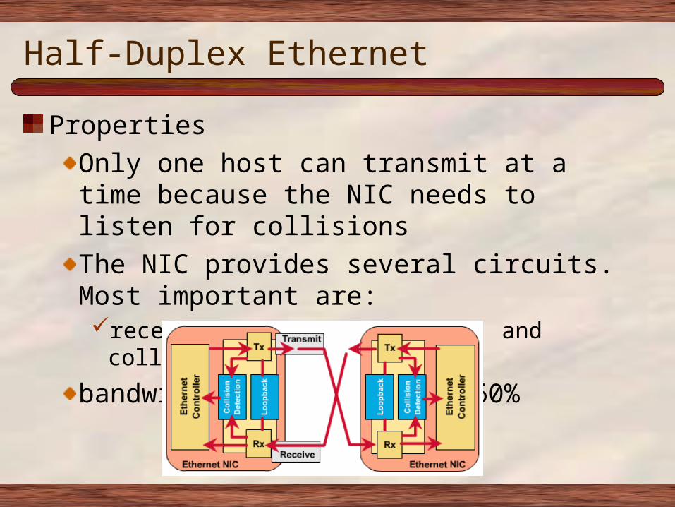
PropertiesOnly one host can transmit at a time because the NIC needs to listen for collisionsThe NIC provides several circuits. Most important are:receive (RX), transmit (TX), and collision detection
bandwidth usage = 50% to 60%
CSMA/CD
OperationDevices on shared media listen for a carrier before transmittingIf no carrier is sensed for a specific period of time, a device can transmitIf two devices transmit simultaneously, a collision occurs. The NIC senses this because it is transmitting and receiving at the same timeThe first device to detect the collision will generate a jam signal (colliding devices continue to transmit so that all devices will hear the collision)All devices calculate a backoff algorithm which will delay transmission for a random length of time.First device who’s delay time expires can attempt to transmit data.
Network Congestion
Occurs as more people utilize a network to...Share large files (e.g. databases, applications, etc.)Access file serversconnect to the Internet
Relieving congestion requiresIncreasing the amount of bandwidth and/orUsing available bandwidth more efficiently
Network Latency
Latency explainedRepresents the time it takes a frame to travel from is source device to its final destination on the network (also know as propagation delay)Latency can also be described as the delay between the time a device requests access to a network and the time it is granted permission to transmitFor switches and routers, latency is the amount of delay between the time when the device receives the frame on one interface and forwards that frame out another interfaceRouters have more inherent latency than a switch. Why?
Ethernet Transmission Time
DefinedTransmission time is the time necessary to move a packet from the data link layer to the physical layer
10BaseT Transmission TimeEach bit has a 100ns window for transmissionns-nanosecond (1 billionth of a second)
So each byte has what size window?A 64 byte frame (the smallest allowed frame) requires 51,200 ns or 51.2 microsecondsJust to frame a 1000 byte packet requires 800 microsecondsAdditional latency will be added propagating the frame down the wire and by any additional devices the frame has to go through before reaching the destination
Using Repeaters
What is attenuation?Loss of signal strength as it travels through the network; caused by resistance inherent in the medium
Benefits of Using a Repeatera layer 1 device that cleans up and boosts the signalextends the coverage area of a LAN segment
Negative Effects of Using a Repeaterincreases the collision domain sizeincreases the broadcast domain sizecan’t filter traffic based on Layer 2 or 3 addressing
Full-Duplex, Fast Ethernet,
and Segmentation
Table of Contents
Full-Duplex Ethernet
Simultaneous TX and RXallows the transmission of a packet and the reception of a different packet at the same time.requires the use of two pairs of wires in the cable and a switched connection between each node.this connection is considered point-to-point and is collision free.because both nodes can transmit and receive at the same time, there are no negotiations for bandwidth.100% of bandwidth is available: 10 Mbps increases to 20 Mbps of potential throughput (10 Mbps TX & 10 Mbps RX)
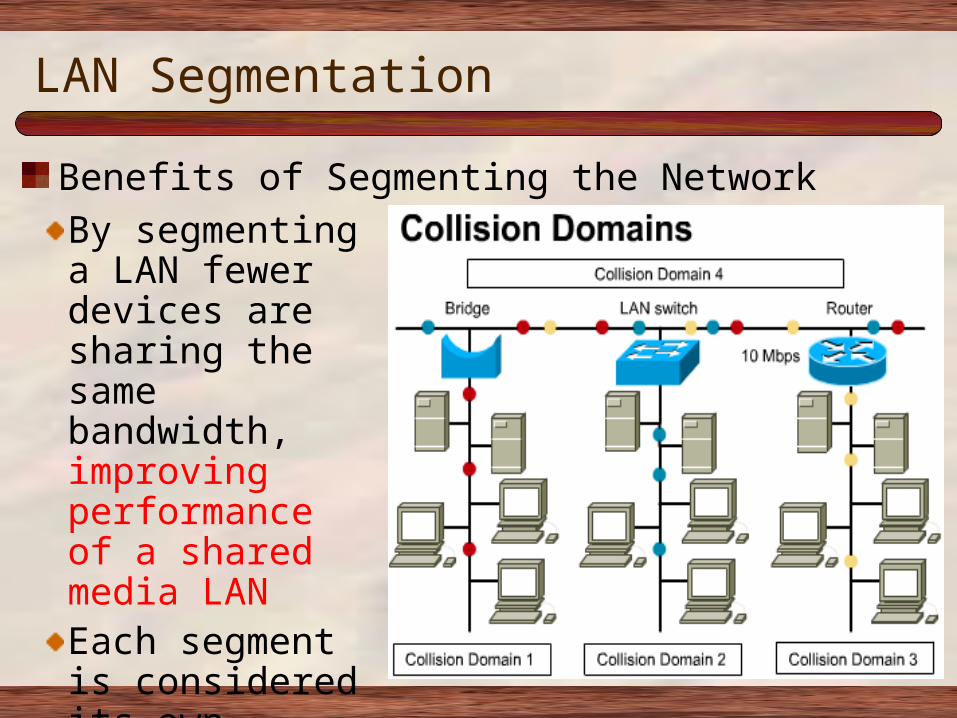
LAN Segmentation
Benefits of Segmenting the NetworkBy segmenting a LAN fewer devices are sharing the same bandwidth, improving performance of a shared media LANEach segment is considered its own collision domainHow many broadcast domains in graphic?
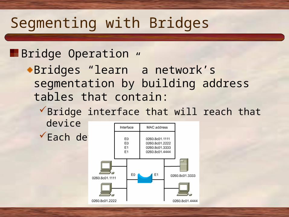
Segmenting with Bridges
Bridge OperationBridges “learn” a network’s segmentation by building address tables that contain:Bridge interface that will reach that deviceEach device’s MAC address
Segmenting with Bridges
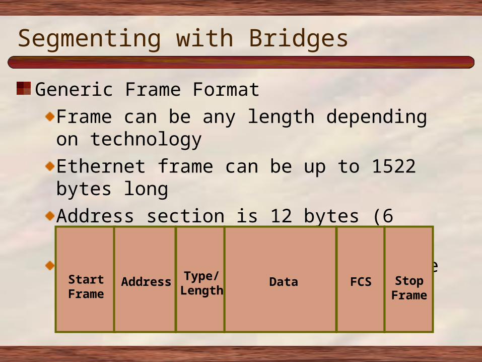
Generic Frame FormatFrame can be any length depending on technologyEthernet frame can be up to 1522 bytes longAddress section is 12 bytes (6 bytes for each MAC)FCS contain the CRC to check frame for errors
AddressStartFrame
Type/Length
Data FCS StopFrame
Segmenting with Bridges
Bridge Performanceadds 10% to 30% latency due to decision-making processconsidered a store-and-forward device because it must calculate the CRC at the end of the frame to check it for errors before forwardingif the bridge does not have an entry for the destination MAC, it...adds the source MAC to its bridging tableforwards the frame out all interfaces except the one it was
received onwhen a reply returns, it adds the destination MAC to the table
Segmenting with Routers
Router OperationRouters...use layer 3 addressing (IP, IPX) and routing protocols (RIP,
IGRP) to determine the path andswitch the packet out the correct interface to the destination
because a router must open the packet to read Layer 3 addressing, it adds latencyIn addition, protocols like TCP which require acknowledgments of every packet can increase latency, reducing throughput from 20% to 40%
Segmenting with Routers
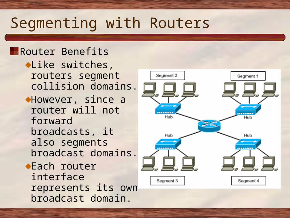
Router BenefitsLike switches, routers segment collision domains.However, since a router will not forward broadcasts, it also segments broadcast domains.Each router interface represents its own broadcast domain.
Segmenting with Switches
Switching Benefitsa switch is simply a multi-port bridge, making forwarding decisions based on MAC addressesso, like a bridge, segmenting a LAN with a switch creates more collision domainsreplacing hubs with switches therefore decreases congestion and increases available bandwidth.a switch can microsegment a LAN creating collision-free domains but still be in the same broadcast domain.switch creates a virtual circuits, allowing many users to communicate in parallel.

Switching and VLANs
Table of Contents
Switch Operation
Switches perform two basic functions:Building and maintaining switching tables (similar to a bridge table) based on MAC addressesSwitching frames out the interface to the destination
Differences between switches & bridgesSwitches operate at higher speedsSwitches are capable of creating virtual LANs (VLANs) through microsegmentationBridges switch using software; switches typically switch using hardware (called the “switch fabric”)
Switch Latency
A switch adds 21 microseconds of latency. This can be reduced by using a different switching methodAs opposed to store-and-forward, the switch can use cut-through switching which switches the packet as soon as the destination MAC is read.
How a LAN Switch Learns Addresses
MAC addresses are learned dynamically and are stored in CAM (content-addressable memory)Each time a switch stores an address entry in the table, it is time-stamped.The time-stamp is updated each time a frame is receivedAddresses whose time-stamp expires are deleted from the tableThis keeps switching tables small
Benefits of LAN Switching
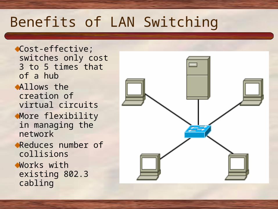
Cost-effective; switches only cost 3 to 5 times that of a hubAllows the creation of virtual circuitsMore flexibility in managing the networkReduces number of collisionsWorks with existing 802.3 cabling
Symmetric Switching
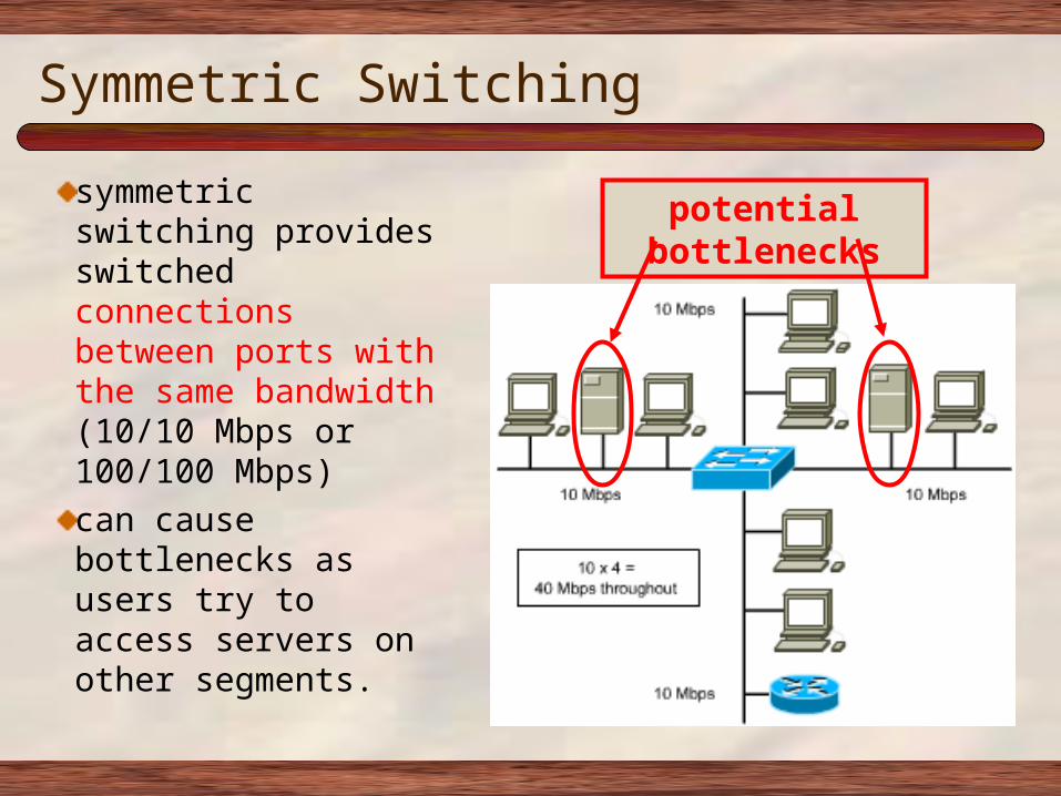
symmetric switching provides switched connections between ports with the same bandwidth (10/10 Mbps or 100/100 Mbps)can cause bottlenecks as users try to access servers on other segments.
potential bottlenecks
Asymmetric Switching
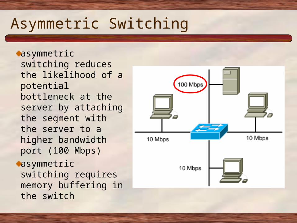
asymmetric switching reduces the likelihood of a potential bottleneck at the server by attaching the segment with the server to a higher bandwidth port (100 Mbps)asymmetric switching requires memory buffering in the switch
Memory Buffering
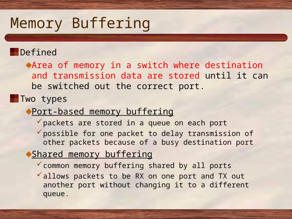
DefinedArea of memory in a switch where destination and transmission data are stored until it can be switched out the correct port.
Two typesPort-based memory bufferingpackets are stored in a queue on each portpossible for one packet to delay transmission of other packets because of a
busy destination port
Shared memory bufferingcommon memory buffering shared by all portsallows packets to be RX on one port and TX out another port without changing
it to a different queue.
Two Switching Methods
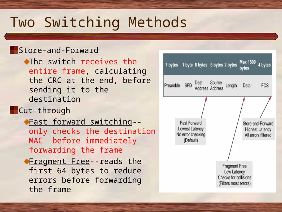
Store-and-ForwardThe switch receives the entire frame, calculating the CRC at the end, before sending it to the destination
Cut-throughFast forward switching--only checks the destination MAC before immediately forwarding the frameFragment Free--reads the first 64 bytes to reduce errors before forwarding the frame
VLANs (IEEE 802.1q)
CharacteristicsA logical grouping of network devices or users that are not restricted to a physical switch segment. The devices or users in a VLAN can be grouped by function, department, application, and so on, regardless of their physical segment location. A VLAN creates a single broadcast domain that is not restricted to a physical segment and is treated like a subnet. VLAN setup is done in the switch by the network administrator using the vendor’s software.

The Spanning-Tree Protocol
Table of Contents
Overview of STP
Elements of the Spanning Tree ProtocolMain function of STP is to allow redundant paths in a switched/bridged network without incurring latency from the effects of loops.STP prevents loops by calculating a stable spanning-tree network topology (similar to OSPF operation)Spanning-tree frames (called bridge protocol data units--BPDUs) are sent and received by all switches in the network and are used to determine the spanning-tree topologySTP operation is covered in detail later in the curriculum.
Five STP States
States are established by configuring each port according to policyThen the STP modifies the states based on traffic patterns and potential loopsThe default order of STP states are:Blocking--no frames forwarded, BPDUs heardListening--no frames forwarded, listening for data framesLearning--no frames forwarded, learning addressesForwarding--frames forwarded, learning addressesDisabled--no frames forwarded, no BPDUs heard
Required Labs for this Chapter
Spend your lab time completing the following labs E-Labs:
From Chapter 1 1.5.13.1From Chapter 1 1.5.13.2 From Chapter 2 2.3.7
For next time: Read Chapter 3Subnet 200.100.100.0 allow for the borrowing of 4 bits and determine the following. # of networks , # of hosts.
Table of Contents
End Slide Show