Embed Size (px)
Citation preview
LAN-50/LAN-500 Ethernet CommunicationLA
N-50/LA
N-500
Application N
ote
1.0 Purpose of this DocumentThis document discusses how to setup, configure, and use the LAN-50 or LAN-500 Universal Device Server to provide LAN/WAN Ethernet connectivity between Doors™ and one or more PXL networks1. The following topics are covered:• Overview• System Requirements• LAN-50/LAN-500 Setup• Doors/Workstation Setup• Using the LAN-50/LAN-500 with Multiple PXL Networks• Basic Ethernet Troubleshooting
2.0 OverviewAt Keri Systems, we are always looking for ways to improve our product and provide solutions to the various implementation requests we receive. One of the most asked for requests is “Can you provide low-cost network capabilities to Doors and a PXL Network?” Although Doors was developed as a stand-alone application, there are a few ways to use Doors in a network2.
The main limitation when using Doors in a network has been that the communication to the PXL network could only come from the host workstation physically connected to the master controller of the PXL network1. This prevents other workstations from using Doors to update or control the PXL network unless either some sort of third party, remote control software application is used or by sharing the Doors folders over a network which places limits on what can be done.
Keri Systems now has a low-cost solution to this problem. The LAN-50 Universal Device Server and LAN-500 Universal Device Server each allow the PXL network to be attached to a Local Area Network (LAN) instead of directly to a host workstation. This gives any workstation on a LAN (with the proper authority) the ability to communicate with the PXL network. To do this, two things must happen.
1. On the host workstation, the Doors folder must be shared.2. A shortcut to the Doors.EXE program in this folder must be created on each client
workstation that needs to be able to run the Doors program. Every client workstation with a shortcut to Doors.EXE can double-click on the shortcut and start the Doors program.
NOTE: Do NOT install the Doors software on each client workstation; this will create unique databases on each system. By creating a shortcut on each client workstation to the shared kerisys folder on the host workstation, each client workstation is able to use the Doors installation on the host workstation, sharing the original database set.
1. The LAN-50 may be used with either a PXL-250 or PXL-500/PXL-510. The LAN-500, however, may be used with a PXL-500/PXL-510 only.
2. See the Doors in a Network Environment Application Note for more information – P/N 01867-001.
Unit 17 Park Farm Industrial Estate 01881-003 Rev. DBuntingford, Herts SG9 9AZ UKTEL: 0870 444 7234 FAX: 0870 444 7240Web: http://www.kerisys.com E-mail: [email protected] Page 1 of 36
LAN-50/LAN-500 Ethernet CommunicationA
pplic
atio
n N
ote
LAN
-50/
LAN
-500
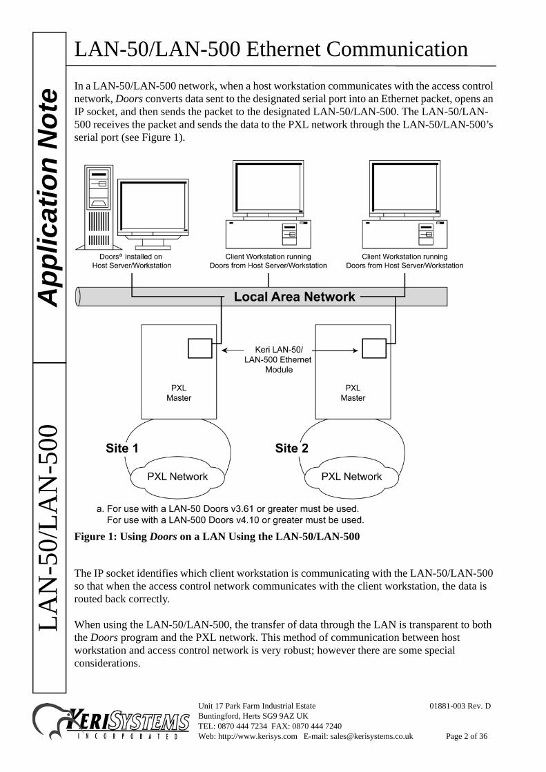
In a LAN-50/LAN-500 network, when a host workstation communicates with the access control network, Doors converts data sent to the designated serial port into an Ethernet packet, opens an IP socket, and then sends the packet to the designated LAN-50/LAN-500. The LAN-50/LAN-500 receives the packet and sends the data to the PXL network through the LAN-50/LAN-500’s serial port (see Figure 1).
Figure 1: Using Doors on a LAN Using the LAN-50/LAN-500
The IP socket identifies which client workstation is communicating with the LAN-50/LAN-500 so that when the access control network communicates with the client workstation, the data is routed back correctly.
When using the LAN-50/LAN-500, the transfer of data through the LAN is transparent to both the Doors program and the PXL network. This method of communication between host workstation and access control network is very robust; however there are some special considerations.
Unit 17 Park Farm Industrial Estate 01881-003 Rev. DBuntingford, Herts SG9 9AZ UKTEL: 0870 444 7234 FAX: 0870 444 7240Web: http://www.kerisys.com E-mail: [email protected] Page 2 of 36
LAN-50/LAN-500 Ethernet CommunicationLA
N-50/LA
N-500
Application N
ote
• Doors software beginning with version 3.61 supports direct communication to the LAN-50.Refer to the Doors Users Guide (P/N 01914-100) for Doors software configuration information.
• Doors software beginning with version 4.10 supports direct communication to the LAN-500. Refer to the Doors Users Guide (P/N 01914-100) for Doors software configuration information
• Whenever a Doors database is opened (i.e. setup users, time zone, access group, controller, door), a copy of that database is saved on the user's client workstation. All changes made by the user are made to that local copy. The original database used by the Doors program on the file server or shared folder does not receive these changes until the user clicks on the SAVE button, physically overwriting the original database in the file server or shared folder with the newly edited information from the user's client workstation. This is done to protect the original database from being affected if a user decides to cancel any changes being made.
• Although multiple users can simultaneously work in the Doors program, only one workstation can communicate with the PXL access control network at a time (whether directly or via remote access software). There is no way to simultaneously control an access control network from more than one workstation. This means that only one user at a time may be downloading information to the network, receiving information from a network, monitoring a network, or manually operating a network. When that user has completed work, that user must use the Net Disconnect command (the Operate > Net Disconnect pull-down menu option) to manually disconnect from the access control network and that user must close the Doors program to allow another user to gain access to the access control network. If more than one workstation is connected to the network at the same time, the first workstation to have changes saved will be the only one connected to the network. All other workstations will not have changes saved until the Net Disconnect has been used at the first workstation.
• There is no encryption available to hide the data going across the LAN. Ethernet, by its nature, is not secure.
• Only one site (or network) may be monitored at any one time.
• PXL initiated communication through the LAN-50/LAN-500 is now supported with the beta version of LAN-50/LAN-500 firmware. For more information on use of the beta firmware allowing PXL initiated communication, refer to the LAN-50/LAN-500 Beta Firmware Application Note (P/N 01922-003).
Unit 17 Park Farm Industrial Estate 01881-003 Rev. DBuntingford, Herts SG9 9AZ UKTEL: 0870 444 7234 FAX: 0870 444 7240Web: http://www.kerisys.com E-mail: [email protected] Page 3 of 36
LAN-50/LAN-500 Ethernet CommunicationA
pplic
atio
n N
ote
LAN
-50/
LAN
-500
3.0 System RequirementsBoth the server and the client workstations, and the LAN must meet the following system requirements for proper operation of Doors and the LAN-50/LAN-500.
• PC compatible computer using a Pentium™-90 or faster microprocessor• minimum of 16 MB of system RAM• SVGA color monitor with SVGA graphics card (800 x 600 minimum resolution for use with
small fonts and 1024 x 768 minimum resolution for use with large fonts)• CD-ROM, keyboard, and mouse or other pointing device• 3.5 inch floppy disk drive or CD-ROM burner (optional for system backup)• 100 MB of available hard disk space• 10BaseT (or greater) network card• twisted-pair network cabling (NOT coax)• TCP/IP network protocol running in a Windows network• one of the following operating systems
- Windows 95™- Windows 98™- Windows 2000™- Windows ME™- Windows XP™ (for Doors v3.74 or greater)- Windows NT™ v4.0 (or greater)
4.0 LAN-50/LAN-500 SetupLAN-50/LAN-500 setup is done in three steps.
1. Connect the LAN-50/LAN-500 to the LAN.2. Set the LAN-50/LAN-500’s IP address.3. Configure the LAN-50/LAN-500.
Once the LAN-50/LAN-500 is setup, the Doors program must be configured to communicate with this unit. Please refer to the Doors Users Guide (P/N 01914-100) for Doors configuration information.
NOTE: To set up the LAN-50/LAN-500 you must have a technical knowledge of networks and networking in a PC environment. Please consult your System or Network Administrator to resolve any networking issues that might occur.
Unit 17 Park Farm Industrial Estate 01881-003 Rev. DBuntingford, Herts SG9 9AZ UKTEL: 0870 444 7234 FAX: 0870 444 7240Web: http://www.kerisys.com E-mail: [email protected] Page 4 of 36
LAN-50/LAN-500 Ethernet CommunicationLA
N-50/LA
N-500
Application N
ote
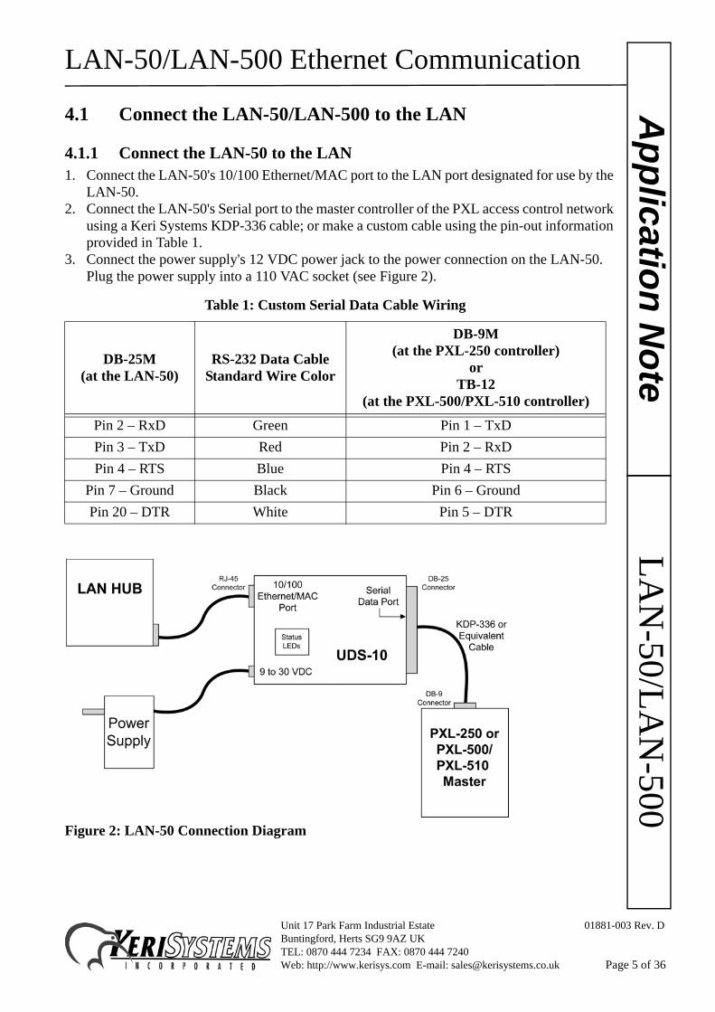
4.1 Connect the LAN-50/LAN-500 to the LAN4.1.1 Connect the LAN-50 to the LAN1. Connect the LAN-50's 10/100 Ethernet/MAC port to the LAN port designated for use by the
LAN-50.2. Connect the LAN-50's Serial port to the master controller of the PXL access control network
using a Keri Systems KDP-336 cable; or make a custom cable using the pin-out information provided in Table 1.
3. Connect the power supply's 12 VDC power jack to the power connection on the LAN-50. Plug the power supply into a 110 VAC socket (see Figure 2).
Figure 2: LAN-50 Connection Diagram
Table 1: Custom Serial Data Cable Wiring
DB-25M(at the LAN-50)
RS-232 Data CableStandard Wire Color
DB-9M(at the PXL-250 controller)
orTB-12
(at the PXL-500/PXL-510 controller)
Pin 2 – RxD Green Pin 1 – TxDPin 3 – TxD Red Pin 2 – RxDPin 4 – RTS Blue Pin 4 – RTS
Pin 7 – Ground Black Pin 6 – GroundPin 20 – DTR White Pin 5 – DTR
Unit 17 Park Farm Industrial Estate 01881-003 Rev. DBuntingford, Herts SG9 9AZ UKTEL: 0870 444 7234 FAX: 0870 444 7240Web: http://www.kerisys.com E-mail: [email protected] Page 5 of 36
LAN-50/LAN-500 Ethernet CommunicationA
pplic
atio
n N
ote
LAN
-50/
LAN
-500
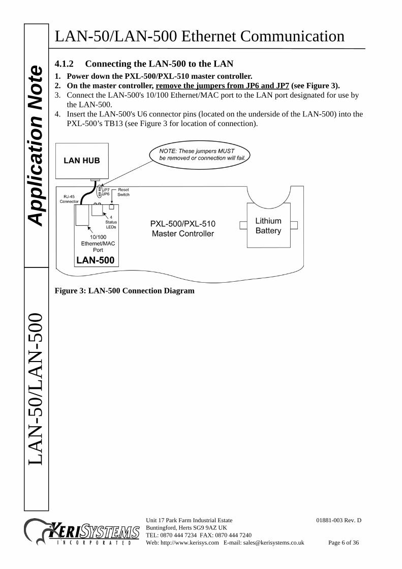
4.1.2 Connecting the LAN-500 to the LAN1. Power down the PXL-500/PXL-510 master controller.2. On the master controller, remove the jumpers from JP6 and JP7 (see Figure 3).3. Connect the LAN-500's 10/100 Ethernet/MAC port to the LAN port designated for use by
the LAN-500.4. Insert the LAN-500's U6 connector pins (located on the underside of the LAN-500) into the
PXL-500’s TB13 (see Figure 3 for location of connection).
Figure 3: LAN-500 Connection Diagram
Unit 17 Park Farm Industrial Estate 01881-003 Rev. DBuntingford, Herts SG9 9AZ UKTEL: 0870 444 7234 FAX: 0870 444 7240Web: http://www.kerisys.com E-mail: [email protected] Page 6 of 36
LAN-50/LAN-500 Ethernet CommunicationLA
N-50/LA
N-500
Application N
ote
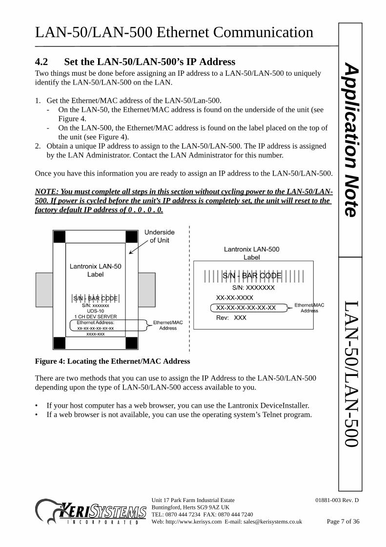
4.2 Set the LAN-50/LAN-500’s IP AddressTwo things must be done before assigning an IP address to a LAN-50/LAN-500 to uniquely identify the LAN-50/LAN-500 on the LAN.1. Get the Ethernet/MAC address of the LAN-50/Lan-500.- On the LAN-50, the Ethernet/MAC address is found on the underside of the unit (see
Figure 4. - On the LAN-500, the Ethernet/MAC address is found on the label placed on the top of
the unit (see Figure 4).2. Obtain a unique IP address to assign to the LAN-50/LAN-500. The IP address is assigned
by the LAN Administrator. Contact the LAN Administrator for this number.
Once you have this information you are ready to assign an IP address to the LAN-50/LAN-500.
NOTE: You must complete all steps in this section without cycling power to the LAN-50/LAN-500. If power is cycled before the unit’s IP address is completely set, the unit will reset to the factory default IP address of 0 . 0 . 0 . 0.
Figure 4: Locating the Ethernet/MAC Address
There are two methods that you can use to assign the IP Address to the LAN-50/LAN-500 depending upon the type of LAN-50/LAN-500 access available to you.
• If your host computer has a web browser, you can use the Lantronix DeviceInstaller.• If a web browser is not available, you can use the operating system’s Telnet program.
Unit 17 Park Farm Industrial Estate 01881-003 Rev. DBuntingford, Herts SG9 9AZ UKTEL: 0870 444 7234 FAX: 0870 444 7240Web: http://www.kerisys.com E-mail: [email protected] Page 7 of 36
LAN-50/LAN-500 Ethernet CommunicationA
pplic
atio
n N
ote
LAN
-50/
LAN
-500
4.2.1 IP Address Assignment Using the Lantronix DeviceInstallerSetting the IP Address via the Lantronix DeviceInstaller is simple, however to use this method you must first download the Lantronix DeviceInstaller. The Lantronix DeviceInstaller is located on the Doors CD-ROM, or may be downloaded from the Lantronix web site at:
ftp://ftp.lantronix.com/priv/DSTConfig/
NOTE: Using the Lantronix DeviceInstaller to assign the IP address is only possible when the installation takes place on the same LAN segment. If the LAN device is located outside the Local LAN segment, the IP address must be assigned manually (see“IP Address Assignment Using Telnet” on page 18).
4.2.1.1 Installation of the Lantronix DeviceInstaller
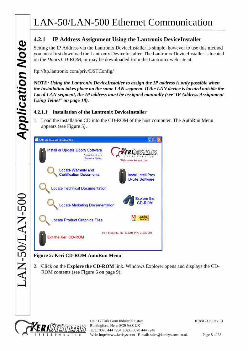
1. Load the installation CD into the CD-ROM of the host computer. The AutoRun Menu appears (see Figure 5).
Figure 5: Keri CD-ROM AutoRun Menu
2. Click on the Explore the CD-ROM link. Windows Explorer opens and displays the CD-ROM contents (see Figure 6 on page 9).
Unit 17 Park Farm Industrial Estate 01881-003 Rev. DBuntingford, Herts SG9 9AZ UKTEL: 0870 444 7234 FAX: 0870 444 7240Web: http://www.kerisys.com E-mail: [email protected] Page 8 of 36
LAN-50/LAN-500 Ethernet CommunicationLA
N-50/LA
N-500
Application N
ote
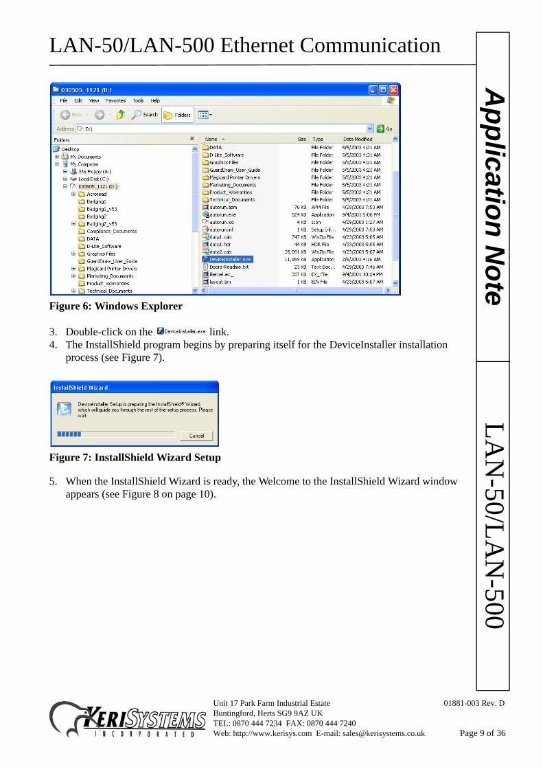
Figure 6: Windows Explorer
3. Double-click on the link.4. The InstallShield program begins by preparing itself for the DeviceInstaller installation
process (see Figure 7).
Figure 7: InstallShield Wizard Setup
5. When the InstallShield Wizard is ready, the Welcome to the InstallShield Wizard window appears (see Figure 8 on page 10).
Unit 17 Park Farm Industrial Estate 01881-003 Rev. DBuntingford, Herts SG9 9AZ UKTEL: 0870 444 7234 FAX: 0870 444 7240Web: http://www.kerisys.com E-mail: [email protected] Page 9 of 36
LAN-50/LAN-500 Ethernet CommunicationA
pplic
atio
n N
ote
LAN
-50/
LAN
-500
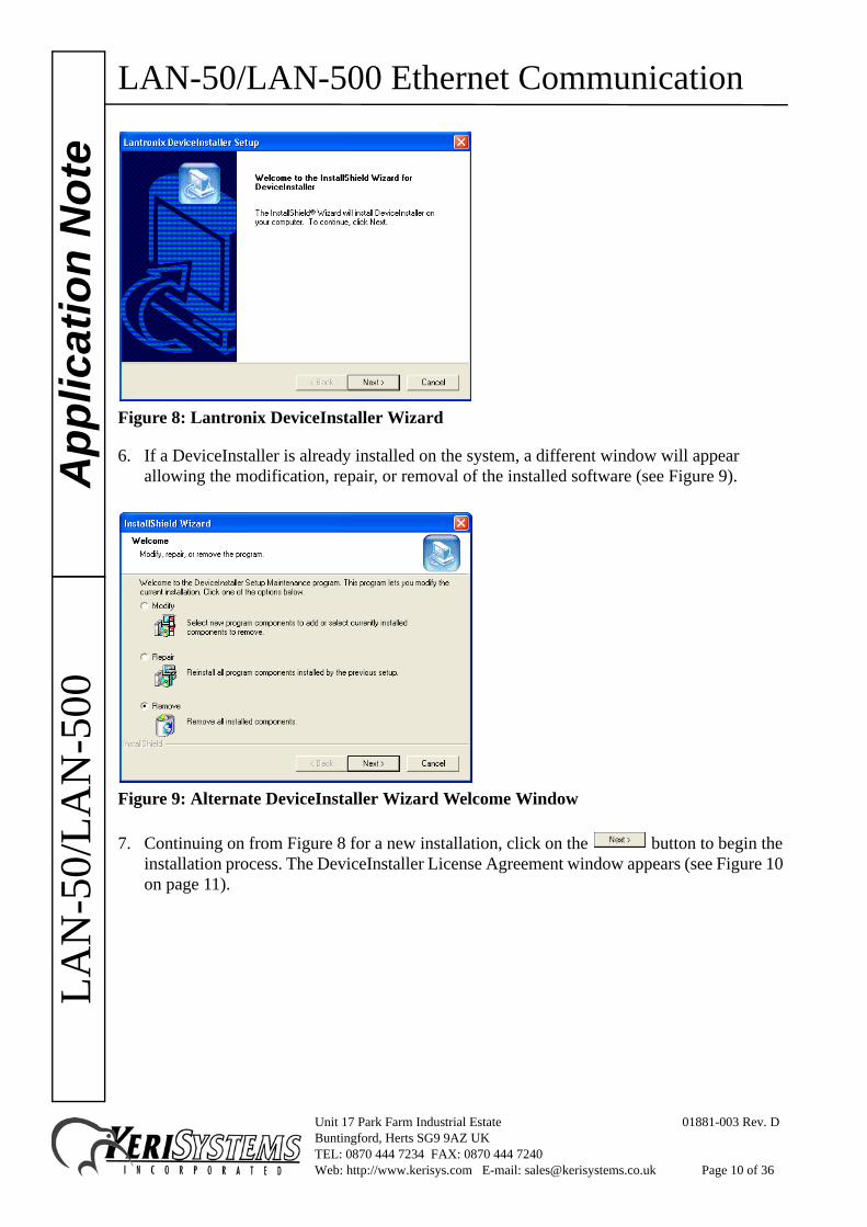
Figure 8: Lantronix DeviceInstaller Wizard
6. If a DeviceInstaller is already installed on the system, a different window will appear allowing the modification, repair, or removal of the installed software (see Figure 9).
Figure 9: Alternate DeviceInstaller Wizard Welcome Window
7. Continuing on from Figure 8 for a new installation, click on the button to begin the installation process. The DeviceInstaller License Agreement window appears (see Figure 10 on page 11).
Unit 17 Park Farm Industrial Estate 01881-003 Rev. DBuntingford, Herts SG9 9AZ UKTEL: 0870 444 7234 FAX: 0870 444 7240Web: http://www.kerisys.com E-mail: [email protected] Page 10 of 36
LAN-50/LAN-500 Ethernet CommunicationLA
N-50/LA
N-500
Application N
ote
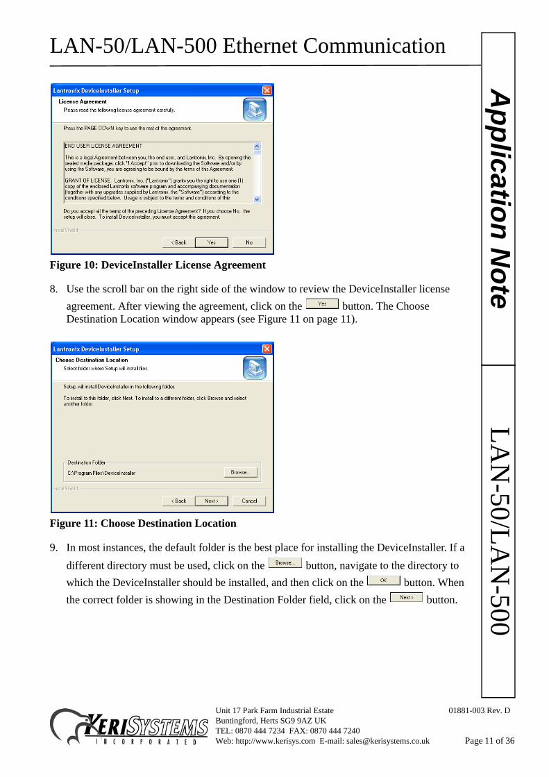
Figure 10: DeviceInstaller License Agreement
8. Use the scroll bar on the right side of the window to review the DeviceInstaller license agreement. After viewing the agreement, click on the button. The Choose Destination Location window appears (see Figure 11 on page 11).
Figure 11: Choose Destination Location
9. In most instances, the default folder is the best place for installing the DeviceInstaller. If a different directory must be used, click on the button, navigate to the directory to which the DeviceInstaller should be installed, and then click on the button. When the correct folder is showing in the Destination Folder field, click on the button.
Unit 17 Park Farm Industrial Estate 01881-003 Rev. DBuntingford, Herts SG9 9AZ UKTEL: 0870 444 7234 FAX: 0870 444 7240Web: http://www.kerisys.com E-mail: [email protected] Page 11 of 36
LAN-50/LAN-500 Ethernet CommunicationA
pplic
atio
n N
ote
LAN
-50/
LAN
-500
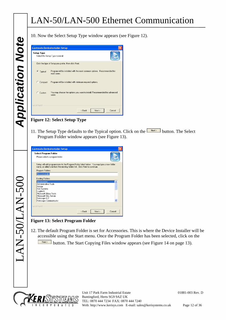
10. Now the Select Setup Type window appears (see Figure 12).
Figure 12: Select Setup Type
11. The Setup Type defaults to the Typical option. Click on the button. The Select Program Folder window appears (see Figure 13).
Figure 13: Select Program Folder
12. The default Program Folder is set for Accessories. This is where the Device Installer will be accessible using the Start menu. Once the Program Folder has been selected, click on the
button. The Start Copying Files window appears (see Figure 14 on page 13).
Unit 17 Park Farm Industrial Estate 01881-003 Rev. DBuntingford, Herts SG9 9AZ UKTEL: 0870 444 7234 FAX: 0870 444 7240Web: http://www.kerisys.com E-mail: [email protected] Page 12 of 36
LAN-50/LAN-500 Ethernet CommunicationLA
N-50/LA
N-500
Application N
ote
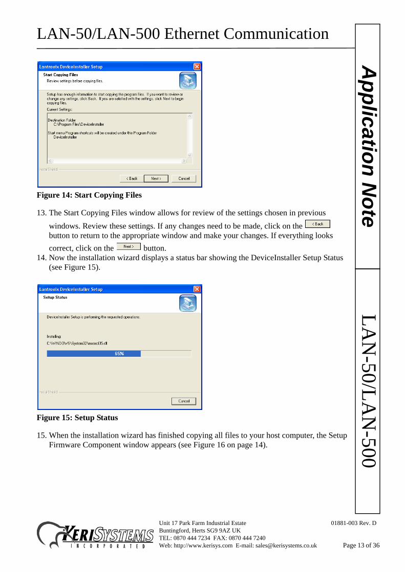
Figure 14: Start Copying Files
13. The Start Copying Files window allows for review of the settings chosen in previous windows. Review these settings. If any changes need to be made, click on the button to return to the appropriate window and make your changes. If everything looks correct, click on the button.
14. Now the installation wizard displays a status bar showing the DeviceInstaller Setup Status (see Figure 15).
Figure 15: Setup Status
15. When the installation wizard has finished copying all files to your host computer, the Setup Firmware Component window appears (see Figure 16 on page 14).
Unit 17 Park Farm Industrial Estate 01881-003 Rev. DBuntingford, Herts SG9 9AZ UKTEL: 0870 444 7234 FAX: 0870 444 7240Web: http://www.kerisys.com E-mail: [email protected] Page 13 of 36
LAN-50/LAN-500 Ethernet CommunicationA
pplic
atio
n N
ote
LAN
-50/
LAN
-500
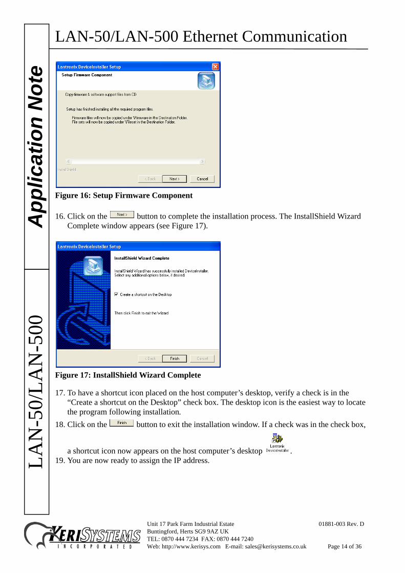
Figure 16: Setup Firmware Component
16. Click on the button to complete the installation process. The InstallShield Wizard Complete window appears (see Figure 17).
Figure 17: InstallShield Wizard Complete
17. To have a shortcut icon placed on the host computer’s desktop, verify a check is in the “Create a shortcut on the Desktop” check box. The desktop icon is the easiest way to locate the program following installation.
18. Click on the button to exit the installation window. If a check was in the check box,
a shortcut icon now appears on the host computer’s desktop .19. You are now ready to assign the IP address.
Unit 17 Park Farm Industrial Estate 01881-003 Rev. DBuntingford, Herts SG9 9AZ UKTEL: 0870 444 7234 FAX: 0870 444 7240Web: http://www.kerisys.com E-mail: [email protected] Page 14 of 36
LAN-50/LAN-500 Ethernet CommunicationLA
N-50/LA
N-500
Application N
ote
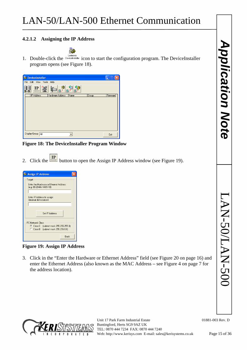
4.2.1.2 Assigning the IP Address1. Double-click the icon to start the configuration program. The DeviceInstaller program opens (see Figure 18).
Figure 18: The DeviceInstaller Program Window
2. Click the button to open the Assign IP Address window (see Figure 19).
Figure 19: Assign IP Address
3. Click in the “Enter the Hardware or Ethernet Address” field (see Figure 20 on page 16) and enter the Ethernet Address (also known as the MAC Address – see Figure 4 on page 7 for the address location).
Unit 17 Park Farm Industrial Estate 01881-003 Rev. DBuntingford, Herts SG9 9AZ UKTEL: 0870 444 7234 FAX: 0870 444 7240Web: http://www.kerisys.com E-mail: [email protected] Page 15 of 36
LAN-50/LAN-500 Ethernet CommunicationA
pplic
atio
n N
ote
LAN
-50/
LAN
-500
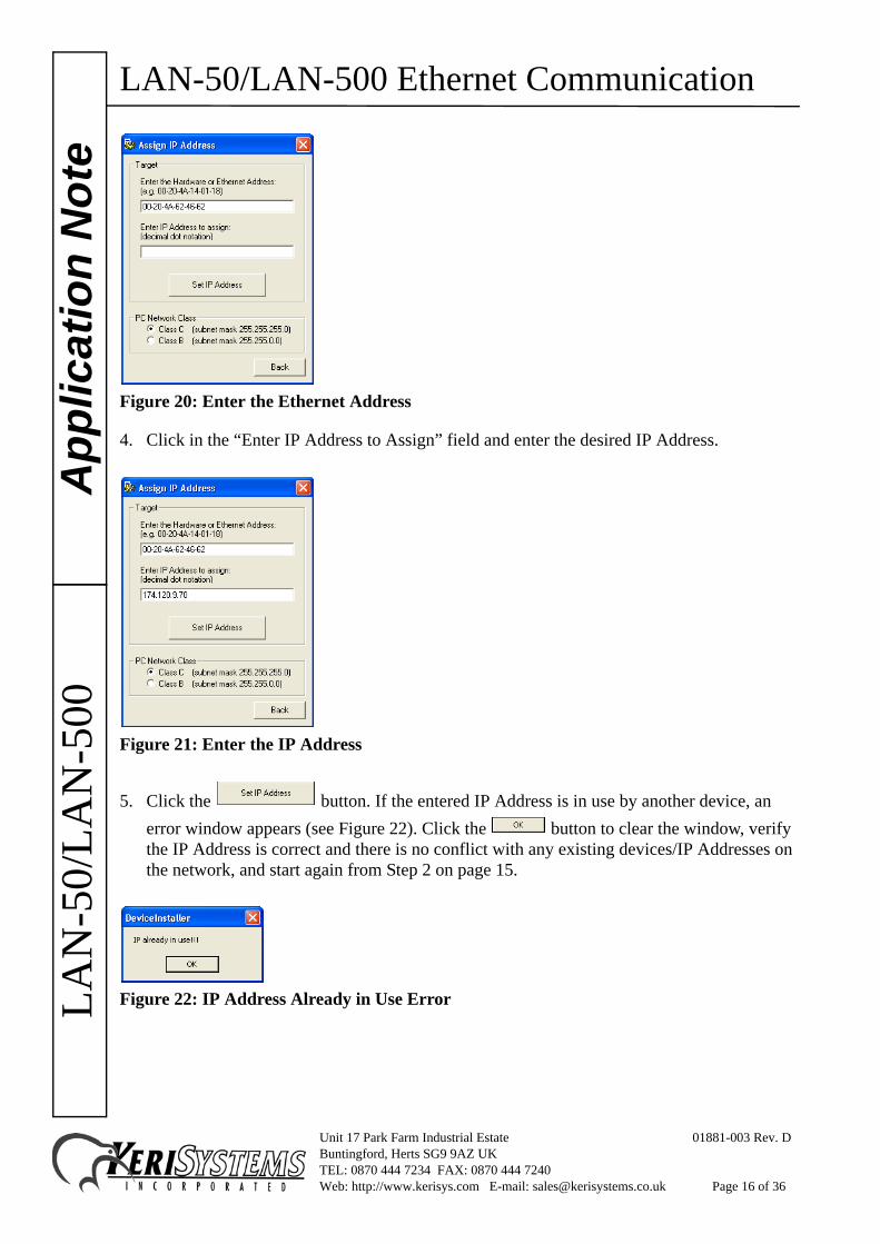
Figure 20: Enter the Ethernet Address
4. Click in the “Enter IP Address to Assign” field and enter the desired IP Address.
Figure 21: Enter the IP Address
5. Click the button. If the entered IP Address is in use by another device, an error window appears (see Figure 22). Click the button to clear the window, verify the IP Address is correct and there is no conflict with any existing devices/IP Addresses on the network, and start again from Step 2 on page 15.
Figure 22: IP Address Already in Use Error
Unit 17 Park Farm Industrial Estate 01881-003 Rev. DBuntingford, Herts SG9 9AZ UKTEL: 0870 444 7234 FAX: 0870 444 7240Web: http://www.kerisys.com E-mail: [email protected] Page 16 of 36
LAN-50/LAN-500 Ethernet CommunicationLA
N-50/LA
N-500
Application N
ote
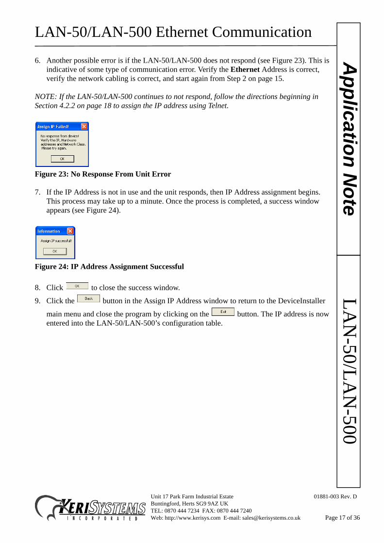
6. Another possible error is if the LAN-50/LAN-500 does not respond (see Figure 23). This isindicative of some type of communication error. Verify the Ethernet Address is correct, verify the network cabling is correct, and start again from Step 2 on page 15.
NOTE: If the LAN-50/LAN-500 continues to not respond, follow the directions beginning in Section 4.2.2 on page 18 to assign the IP address using Telnet.
Figure 23: No Response From Unit Error
7. If the IP Address is not in use and the unit responds, then IP Address assignment begins. This process may take up to a minute. Once the process is completed, a success window appears (see Figure 24).
Figure 24: IP Address Assignment Successful
8. Click to close the success window.
9. Click the button in the Assign IP Address window to return to the DeviceInstaller
main menu and close the program by clicking on the button. The IP address is now entered into the LAN-50/LAN-500’s configuration table.
Unit 17 Park Farm Industrial Estate 01881-003 Rev. DBuntingford, Herts SG9 9AZ UKTEL: 0870 444 7234 FAX: 0870 444 7240Web: http://www.kerisys.com E-mail: [email protected] Page 17 of 36
LAN-50/LAN-500 Ethernet CommunicationA
pplic
atio
n N
ote
LAN
-50/
LAN
-500
4.2.2 IP Address Assignment Using TelnetThe LAN-50/LAN-500 takes its IP address from the first TCP/IP packet directed to that unit via the unit’s Ethernet/MAC address. Once the first packet with the IP address has been sent, Telnet is used to permanently set this IP address in the unit.
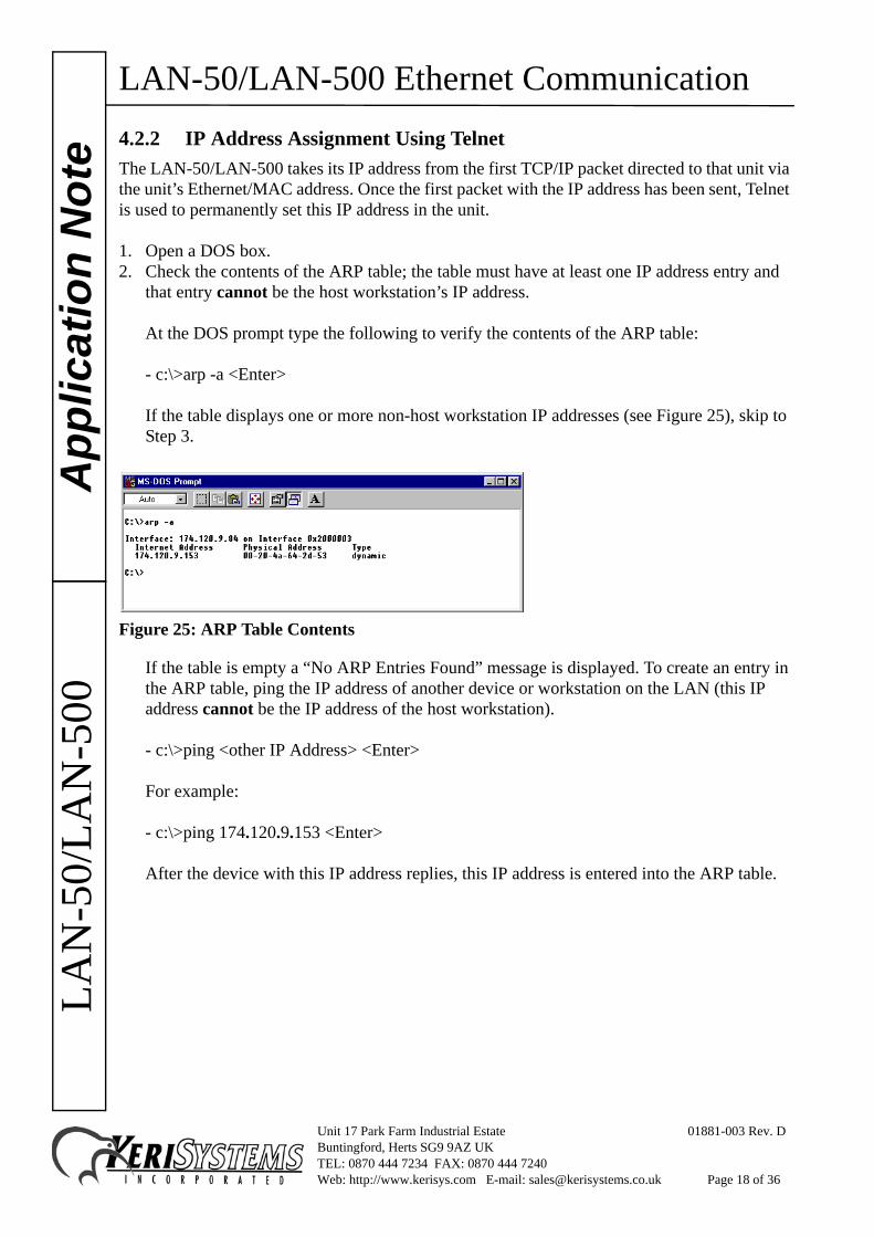
1. Open a DOS box.2. Check the contents of the ARP table; the table must have at least one IP address entry and
that entry cannot be the host workstation’s IP address.
At the DOS prompt type the following to verify the contents of the ARP table:
- c:\>arp -a <Enter>
If the table displays one or more non-host workstation IP addresses (see Figure 25), skip to Step 3.
Figure 25: ARP Table Contents
If the table is empty a “No ARP Entries Found” message is displayed. To create an entry in the ARP table, ping the IP address of another device or workstation on the LAN (this IP address cannot be the IP address of the host workstation).
- c:\>ping <other IP Address> <Enter>
For example:
- c:\>ping 174.120.9.153 <Enter>
After the device with this IP address replies, this IP address is entered into the ARP table.
Unit 17 Park Farm Industrial Estate 01881-003 Rev. DBuntingford, Herts SG9 9AZ UKTEL: 0870 444 7234 FAX: 0870 444 7240Web: http://www.kerisys.com E-mail: [email protected] Page 18 of 36
LAN-50/LAN-500 Ethernet CommunicationLA
N-50/LA
N-500
Application N
ote
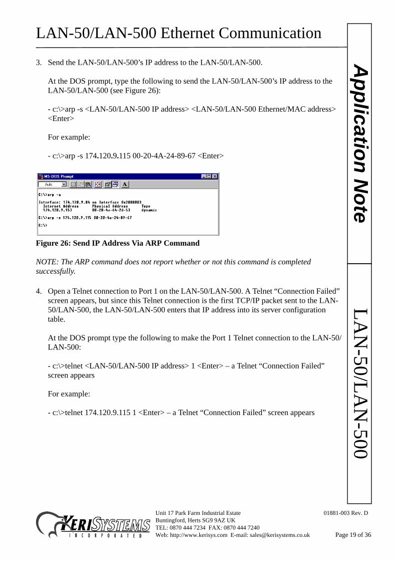
3. Send the LAN-50/LAN-500’s IP address to the LAN-50/LAN-500.At the DOS prompt, type the following to send the LAN-50/LAN-500’s IP address to the LAN-50/LAN-500 (see Figure 26):
- c:\>arp -s <LAN-50/LAN-500 IP address> <LAN-50/LAN-500 Ethernet/MAC address> <Enter>
For example:
- c:\>arp -s 174.120.9.115 00-20-4A-24-89-67 <Enter>
Figure 26: Send IP Address Via ARP Command
NOTE: The ARP command does not report whether or not this command is completed successfully.
4. Open a Telnet connection to Port 1 on the LAN-50/LAN-500. A Telnet “Connection Failed” screen appears, but since this Telnet connection is the first TCP/IP packet sent to the LAN-50/LAN-500, the LAN-50/LAN-500 enters that IP address into its server configuration table.
At the DOS prompt type the following to make the Port 1 Telnet connection to the LAN-50/LAN-500:
- c:\>telnet <LAN-50/LAN-500 IP address> 1 <Enter> – a Telnet “Connection Failed” screen appears
For example:
- c:\>telnet 174.120.9.115 1 <Enter> – a Telnet “Connection Failed” screen appears
Unit 17 Park Farm Industrial Estate 01881-003 Rev. DBuntingford, Herts SG9 9AZ UKTEL: 0870 444 7234 FAX: 0870 444 7240Web: http://www.kerisys.com E-mail: [email protected] Page 19 of 36
LAN-50/LAN-500 Ethernet CommunicationA
pplic
atio
n N
ote
LAN
-50/
LAN
-500
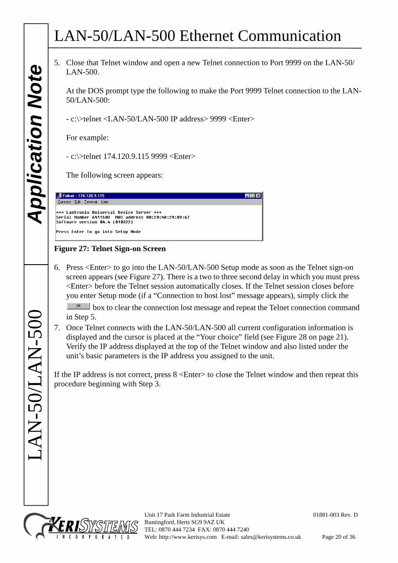
5. Close that Telnet window and open a new Telnet connection to Port 9999 on the LAN-50/LAN-500.
At the DOS prompt type the following to make the Port 9999 Telnet connection to the LAN-50/LAN-500:
- c:\>telnet <LAN-50/LAN-500 IP address> 9999 <Enter>
For example:
- c:\>telnet 174.120.9.115 9999 <Enter>
The following screen appears:
Figure 27: Telnet Sign-on Screen
6. Press <Enter> to go into the LAN-50/LAN-500 Setup mode as soon as the Telnet sign-on screen appears (see Figure 27). There is a two to three second delay in which you must press <Enter> before the Telnet session automatically closes. If the Telnet session closes before you enter Setup mode (if a “Connection to host lost” message appears), simply click the
box to clear the connection lost message and repeat the Telnet connection command in Step 5.
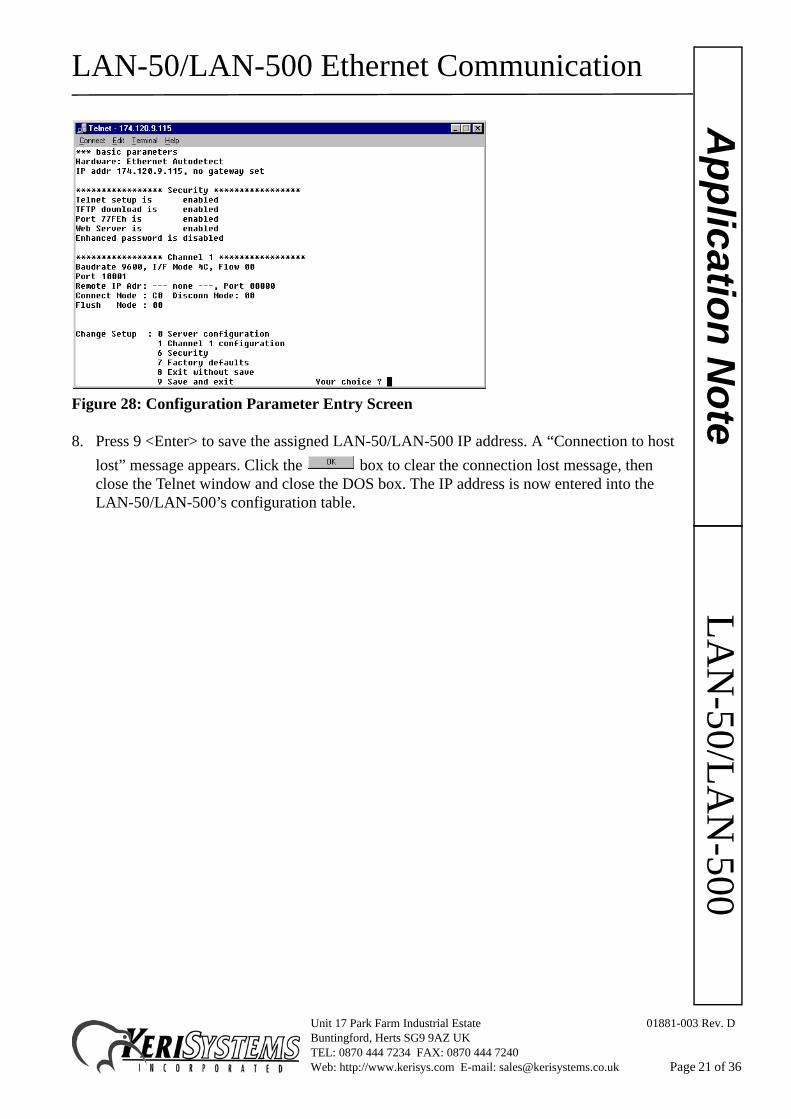
7. Once Telnet connects with the LAN-50/LAN-500 all current configuration information is displayed and the cursor is placed at the “Your choice” field (see Figure 28 on page 21). Verify the IP address displayed at the top of the Telnet window and also listed under the unit’s basic parameters is the IP address you assigned to the unit.
If the IP address is not correct, press 8 <Enter> to close the Telnet window and then repeat this procedure beginning with Step 3.
Unit 17 Park Farm Industrial Estate 01881-003 Rev. DBuntingford, Herts SG9 9AZ UKTEL: 0870 444 7234 FAX: 0870 444 7240Web: http://www.kerisys.com E-mail: [email protected] Page 20 of 36
LAN-50/LAN-500 Ethernet CommunicationLA
N-50/LA
N-500
Application N
ote
Figure 28: Configuration Parameter Entry Screen8. Press 9 <Enter> to save the assigned LAN-50/LAN-500 IP address. A “Connection to host lost” message appears. Click the box to clear the connection lost message, then close the Telnet window and close the DOS box. The IP address is now entered into the LAN-50/LAN-500’s configuration table.
Unit 17 Park Farm Industrial Estate 01881-003 Rev. DBuntingford, Herts SG9 9AZ UKTEL: 0870 444 7234 FAX: 0870 444 7240Web: http://www.kerisys.com E-mail: [email protected] Page 21 of 36
LAN-50/LAN-500 Ethernet CommunicationA
pplic
atio
n N
ote
LAN
-50/
LAN
-500
4.3 Resetting or Rebooting a LAN-50/LAN-500Resetting a LAN-50/LAN-500 restores all serial port parameters to the factory default values. Rebooting a LAN-50/LAN-500 restarts the unit should the unit be hung up.
NOTE: If you need to change an IP address on a LAN-50/LAN-500, this can only be done through the DeviceInstaller program. Simply follow the steps for assigning an IP address (see Section 4.2.1 on page 8). However, Telnet must be used if the IP address is outside of the subnet scheme for the LAN (see Section 4.2.2 on page 18).
4.3.1 Resetting the UnitResetting a LAN-50/LAN-500 must be done via Telnet.
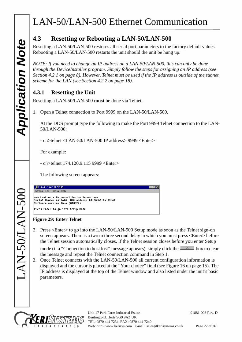
1. Open a Telnet connection to Port 9999 on the LAN-50/LAN-500.
At the DOS prompt type the following to make the Port 9999 Telnet connection to the LAN-50/LAN-500:
- c:\>telnet <LAN-50/LAN-500 IP address> 9999 <Enter>
For example:
- c:\>telnet 174.120.9.115 9999 <Enter>
The following screen appears:
Figure 29: Enter Telnet
2. Press <Enter> to go into the LAN-50/LAN-500 Setup mode as soon as the Telnet sign-on screen appears. There is a two to three second delay in which you must press <Enter> before the Telnet session automatically closes. If the Telnet session closes before you enter Setup mode (if a “Connection to host lost” message appears), simply click the box to clear the message and repeat the Telnet connection command in Step 1.
3. Once Telnet connects with the LAN-50/LAN-500 all current configuration information is displayed and the cursor is placed at the “Your choice” field (see Figure 16 on page 15). The IP address is displayed at the top of the Telnet window and also listed under the unit’s basic parameters.
Unit 17 Park Farm Industrial Estate 01881-003 Rev. DBuntingford, Herts SG9 9AZ UKTEL: 0870 444 7234 FAX: 0870 444 7240Web: http://www.kerisys.com E-mail: [email protected] Page 22 of 36
LAN-50/LAN-500 Ethernet CommunicationLA
N-50/LA
N-500
Application N
ote
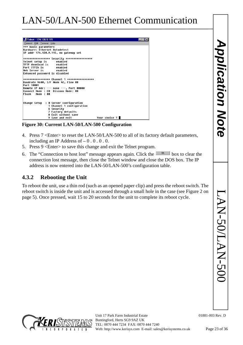
Figure 30: Current LAN-50/LAN-500 Configuration4. Press 7 <Enter> to reset the LAN-50/LAN-500 to all of its factory default parameters, including an IP Address of – 0 . 0 . 0 . 0.
5. Press 9 <Enter> to save this change and exit the Telnet program.6. The “Connection to host lost” message appears again. Click the box to clear the
connection lost message, then close the Telnet window and close the DOS box. The IP address is now entered into the LAN-50/LAN-500’s configuration table.
4.3.2 Rebooting the UnitTo reboot the unit, use a thin rod (such as an opened paper clip) and press the reboot switch. The reboot switch is inside the unit and is accessed through a small hole in the case (see Figure 2 on page 5). Once pressed, wait 15 to 20 seconds for the unit to complete its reboot cycle.
Unit 17 Park Farm Industrial Estate 01881-003 Rev. DBuntingford, Herts SG9 9AZ UKTEL: 0870 444 7234 FAX: 0870 444 7240Web: http://www.kerisys.com E-mail: [email protected] Page 23 of 36
LAN-50/LAN-500 Ethernet CommunicationA
pplic
atio
n N
ote
LAN
-50/
LAN
-500
4.4 Configure the LAN-50/LAN-500LAN-50/LAN-500 configuration can be done either via a Telnet connection or a web browser connection (provided the LAN-50/LAN-500 has the appropriate firmware revision). The same configuration parameter values apply regardless of configuration method used. This section identifies the configuration parameter values that must be set for proper operation of the LAN-50/LAN-500 with Doors and then describes the two configuration processes. Use the configuration process that is easiest for you.
4.4.1 Required LAN-50/LAN-500 Configuration ParametersThe primary difference in how configuration parameters are handled between Telnet and web browsing is that several groups of related of parameter values that are entered individually by web browsing are bundled together in a hex code and then entered when using Telnet. When entering configuration parameters, if an individual parameter is not called out in the instructions below, the factory default value should be left in place.
4.4.2 Configuration via Web BrowserThere are a number of critical parameters to set via web browser. These parameters are identified in this section. All other parameters should be left at their default values.
NOTE: To configure the LAN-50/LAN-500 via web browser the browser must be Java enabled.
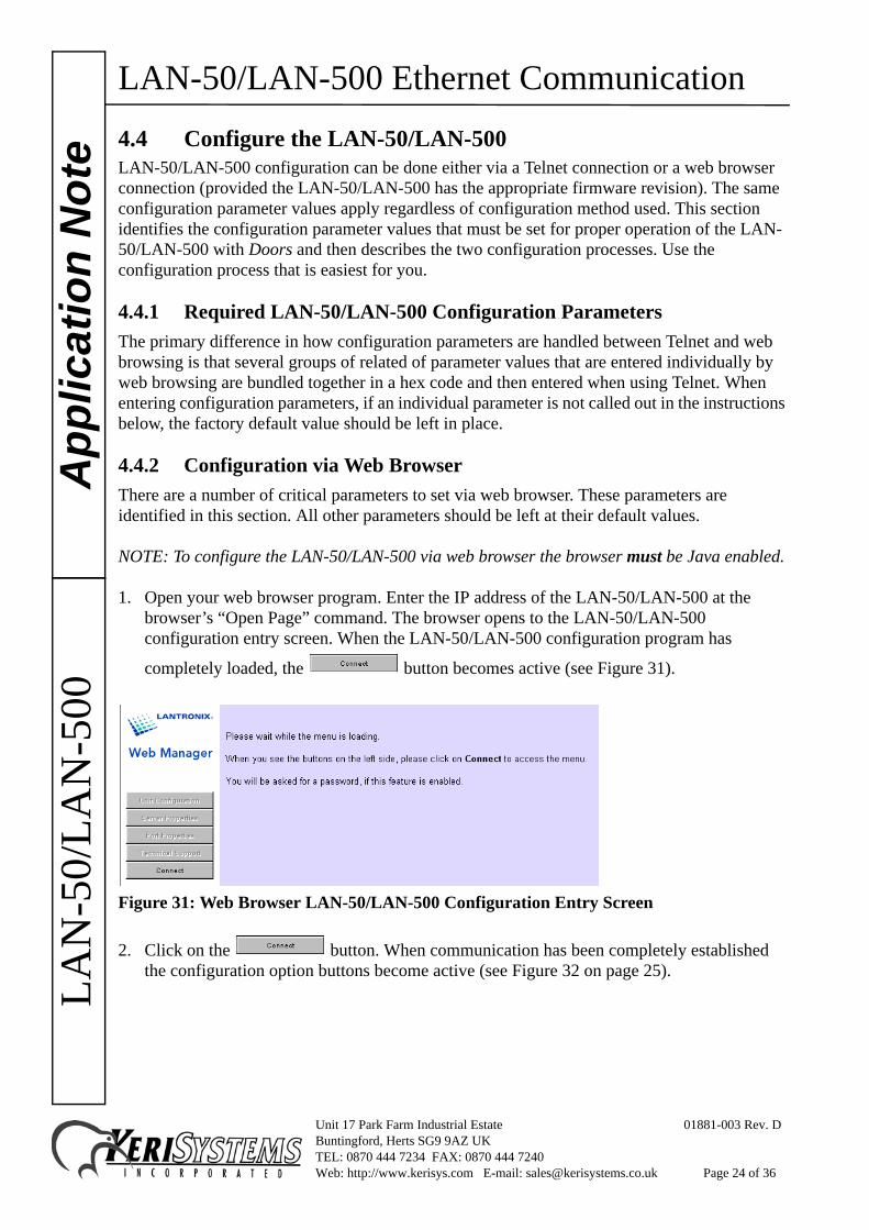
1. Open your web browser program. Enter the IP address of the LAN-50/LAN-500 at the browser’s “Open Page” command. The browser opens to the LAN-50/LAN-500 configuration entry screen. When the LAN-50/LAN-500 configuration program has
completely loaded, the button becomes active (see Figure 31).
Figure 31: Web Browser LAN-50/LAN-500 Configuration Entry Screen
2. Click on the button. When communication has been completely established the configuration option buttons become active (see Figure 32 on page 25).
Unit 17 Park Farm Industrial Estate 01881-003 Rev. DBuntingford, Herts SG9 9AZ UKTEL: 0870 444 7234 FAX: 0870 444 7240Web: http://www.kerisys.com E-mail: [email protected] Page 24 of 36
LAN-50/LAN-500 Ethernet CommunicationLA
N-50/LA
N-500
Application N
ote
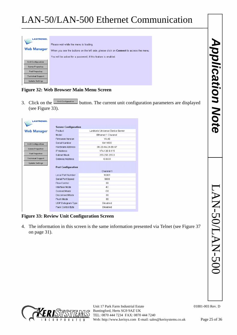
Figure 32: Web Browser Main Menu Screen
3. Click on the button. The current unit configuration parameters are displayed (see Figure 33).
Figure 33: Review Unit Configuration Screen
4. The information in this screen is the same information presented via Telnet (see Figure 37 on page 31).
Unit 17 Park Farm Industrial Estate 01881-003 Rev. DBuntingford, Herts SG9 9AZ UKTEL: 0870 444 7234 FAX: 0870 444 7240Web: http://www.kerisys.com E-mail: [email protected] Page 25 of 36
LAN-50/LAN-500 Ethernet CommunicationA
pplic
atio
n N
ote
LAN
-50/
LAN
-500
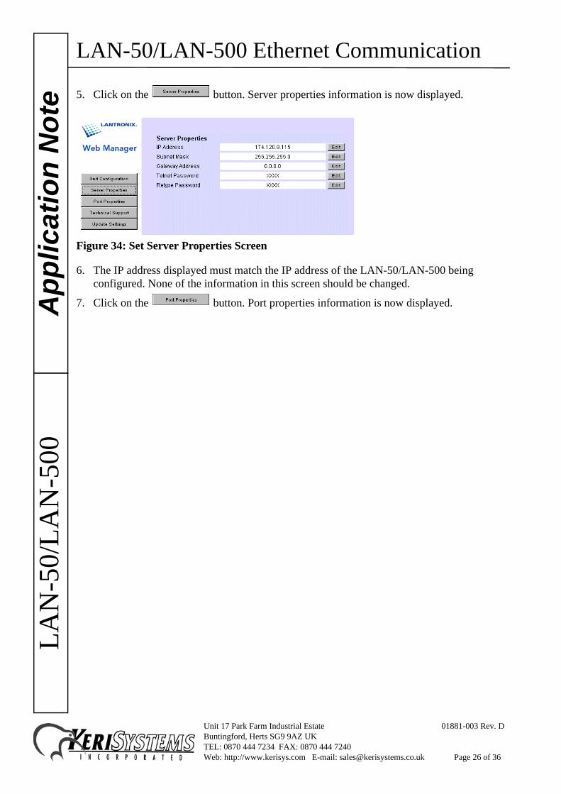
5. Click on the button. Server properties information is now displayed.
Figure 34: Set Server Properties Screen
6. The IP address displayed must match the IP address of the LAN-50/LAN-500 being configured. None of the information in this screen should be changed.
7. Click on the button. Port properties information is now displayed.
Unit 17 Park Farm Industrial Estate 01881-003 Rev. DBuntingford, Herts SG9 9AZ UKTEL: 0870 444 7234 FAX: 0870 444 7240Web: http://www.kerisys.com E-mail: [email protected] Page 26 of 36
LAN-50/LAN-500 Ethernet CommunicationLA
N-50/LA
N-500
Application N
ote
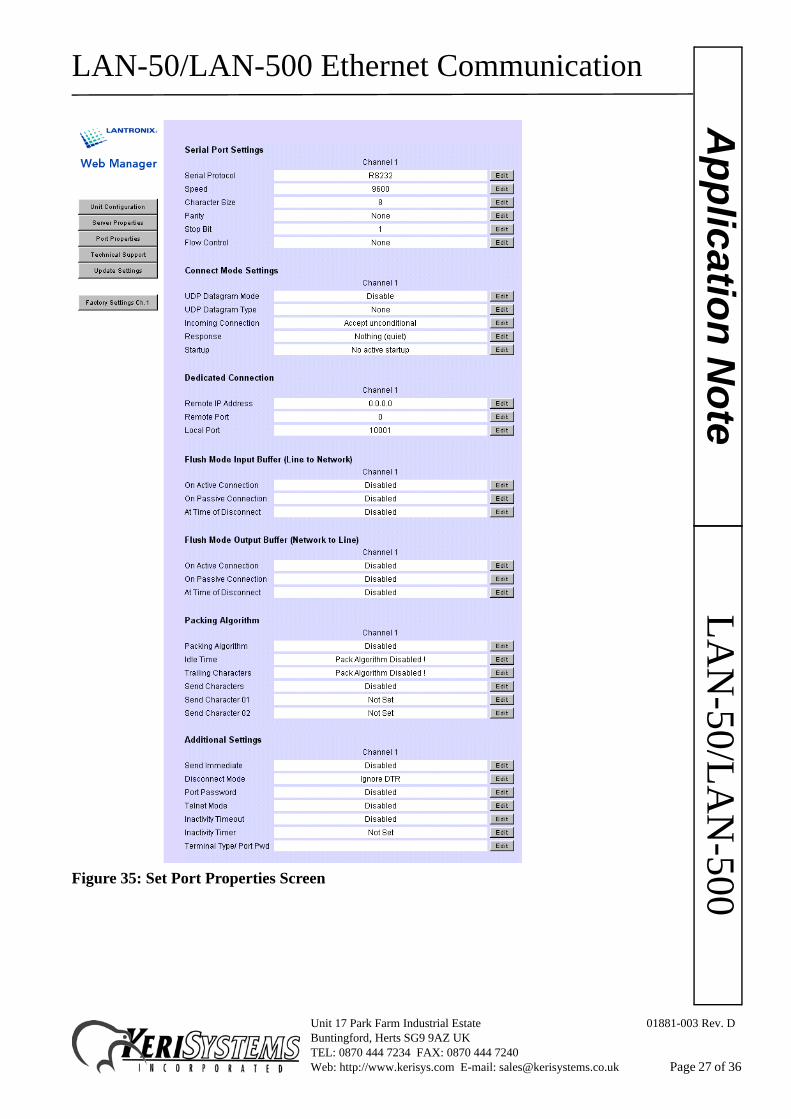
Figure 35: Set Port Properties Screen
Unit 17 Park Farm Industrial Estate 01881-003 Rev. DBuntingford, Herts SG9 9AZ UKTEL: 0870 444 7234 FAX: 0870 444 7240Web: http://www.kerisys.com E-mail: [email protected] Page 27 of 36
LAN-50/LAN-500 Ethernet CommunicationA
pplic
atio
n N
ote
LAN
-50/
LAN
-500
8. Verify the following parameters are set to the specified values. If any of these parameters are incorrect, click on the button. Depending upon the field, you have two options for entering the appropriate configuration value.
• select the correct value from a list of entries• type in the correct value
Verify the following values. Parameters not called out in the following list should be left at their default values.
Serial Port Settings to Verify- Serial Protocol = RS232- Speed = 9600- Character Size = 8- Parity = None- Stop Bit = 1- Flow Control = None
Connect Mode Settings to Verify- Incoming Connection = Accept Unconditional- Response = Nothing (Quiet)- Startup = No Active Startup
Dedicated Connection Settings to Verify- Local Port = 10001
Additional Settings- Disconnect Mode = Ignore DTR
9. Once all these parameters have been verified/entered, click the button. The parameter information is sent to the LAN-50/LAN-500 and the LAN-50/LAN-500 is rebooted to have these new values take effect. Once the LAN-50/LAN-500 has rebooted the unit configuration screen reappears (see Figure 33 on page 25). The LAN-50/LAN-500 is now ready for use.
Unit 17 Park Farm Industrial Estate 01881-003 Rev. DBuntingford, Herts SG9 9AZ UKTEL: 0870 444 7234 FAX: 0870 444 7240Web: http://www.kerisys.com E-mail: [email protected] Page 28 of 36
LAN-50/LAN-500 Ethernet CommunicationLA
N-50/LA
N-500
Application N
ote
4.4.3 Configuration via TelnetThere are only two critical parameters to set via Telnet (I/F Mode and Connect Mode); all other parameters should be left at their default values.NOTE: For information on how to configure the LAN-50/LAN-500 to allow for PXL initiated connections using the beta firmware, refer to the LAN-50/LAN-500 Beta Firmware Application Note (P/N 01922-003).
1. Open a DOS box and open a Telnet connection to Port 9999 on the LAN-50/LAN-500.
At the DOS prompt type the following to make the Port 9999 Telnet connection to the LAN-50/LAN-500:
- c:\>telnet <LAN-50/LAN-500 IP address> 9999 <Enter>
For example:
- c:\>telnet 174.120.9.115 9999 <Enter>
2. Press <Enter> to go into the LAN-50/LAN-500 Setup mode as soon as the Telnet sign-on screen appears. There is a two to three second delay in which you must press <Enter> before the Telnet session automatically closes. If the Telnet session closes before you enter Setup mode (if a “Connection to host lost” message appears), simply click the box to clear the connection lost message and repeat the Telnet connection command in Step 1.
3. Once Telnet connects with the LAN-50/LAN-500 all current configuration information is displayed and the cursor is placed at the “Your choice” field (see Figure 30 on page 23).
4. Press 1 <Enter> to enter the Channel 1 Configuration values. The first configuration parameter is displayed (see Figure 36 on page 30).
Unit 17 Park Farm Industrial Estate 01881-003 Rev. DBuntingford, Herts SG9 9AZ UKTEL: 0870 444 7234 FAX: 0870 444 7240Web: http://www.kerisys.com E-mail: [email protected] Page 29 of 36
LAN-50/LAN-500 Ethernet CommunicationA
pplic
atio
n N
ote
LAN
-50/
LAN
-500
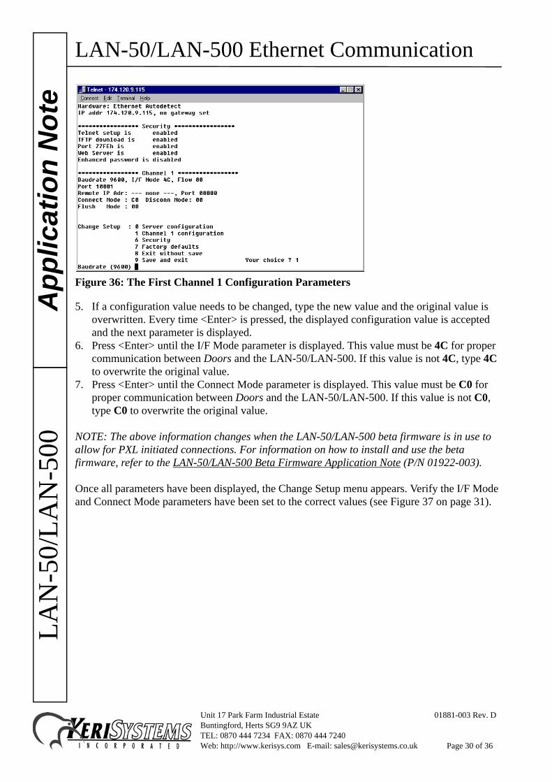
Figure 36: The First Channel 1 Configuration Parameters
5. If a configuration value needs to be changed, type the new value and the original value is overwritten. Every time <Enter> is pressed, the displayed configuration value is accepted and the next parameter is displayed.
6. Press <Enter> until the I/F Mode parameter is displayed. This value must be 4C for proper communication between Doors and the LAN-50/LAN-500. If this value is not 4C, type 4C to overwrite the original value.
7. Press <Enter> until the Connect Mode parameter is displayed. This value must be C0 for proper communication between Doors and the LAN-50/LAN-500. If this value is not C0, type C0 to overwrite the original value.
NOTE: The above information changes when the LAN-50/LAN-500 beta firmware is in use to allow for PXL initiated connections. For information on how to install and use the beta firmware, refer to the LAN-50/LAN-500 Beta Firmware Application Note (P/N 01922-003).
Once all parameters have been displayed, the Change Setup menu appears. Verify the I/F Mode and Connect Mode parameters have been set to the correct values (see Figure 37 on page 31).
Unit 17 Park Farm Industrial Estate 01881-003 Rev. DBuntingford, Herts SG9 9AZ UKTEL: 0870 444 7234 FAX: 0870 444 7240Web: http://www.kerisys.com E-mail: [email protected] Page 30 of 36
LAN-50/LAN-500 Ethernet CommunicationLA
N-50/LA
N-500
Application N
ote
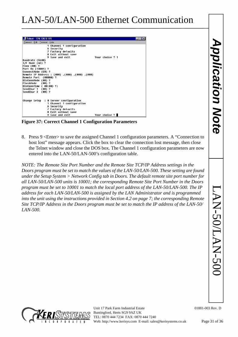
Figure 37: Correct Channel 1 Configuration Parameters8. Press 9 <Enter> to save the assigned Channel 1 configuration parameters. A “Connection to
host lost” message appears. Click the box to clear the connection lost message, then close the Telnet window and close the DOS box. The Channel 1 configuration parameters are now entered into the LAN-50/LAN-500’s configuration table.
NOTE: The Remote Site Port Number and the Remote Site TCP/IP Address settings in the Doors program must be set to match the values of the LAN-50/LAN-500. These setting are found under the Setup System > Network Config tab in Doors. The default remote site port number for all LAN-50/LAN-500 units is 10001; the corresponding Remote Site Port Number in the Doors program must be set to 10001 to match the local port address of the LAN-50/LAN-500. The IP address for each LAN-50/LAN-500 is assigned by the LAN Administrator and is programmed into the unit using the instructions provided in Section 4.2 on page 7; the corresponding Remote Site TCP/IP Address in the Doors program must be set to match the IP address of the LAN-50/LAN-500.
Unit 17 Park Farm Industrial Estate 01881-003 Rev. DBuntingford, Herts SG9 9AZ UKTEL: 0870 444 7234 FAX: 0870 444 7240Web: http://www.kerisys.com E-mail: [email protected] Page 31 of 36
LAN-50/LAN-500 Ethernet CommunicationA
pplic
atio
n N
ote
LAN
-50/
LAN
-500
5.0 Using Doors Databases over a NetworkWhenever a Doors database is opened (i.e. cardholder, time zone, access group, controller, door), a copy of that database is saved on the user's workstation. All changes made by the user are made to that local copy. The original database used by the Doors program on the file server
or shared folder does not receive these changes until the user clicks on the button, physically overwriting the original database in the file server or shared folder with the newly edited information from the user's workstation. This is done to protect the original database from being affected if a user decides to cancel any changes being made.
What this means is that there can be database change conflicts if multiple users edit the same database simultaneously. There are two situations in which this can occur.
1. There are no notifications to indicate a database has been changed since the last time a user opened that database. If User-A and User-B both have the same database open and User-B saves changes to that database, User-A must close the database and then reopen it to see the changes made by User-B.
2. Suppose User-A and User-B have the same database open and both are making changes to that database. If User-A saves one set of changes and then User-B saves a different set of changes, the changes made by User-B (the last set of changes saved) will overwrite the changes made by User-A.
For these reasons, Keri Systems strongly recommends that only one user/workstation be allowed to view or modify a database at a time. Although multiple users can simultaneously work in the Doors program, only one workstation can communicate with the access control network at a time (using a direct connection or via remote control software). There is no way to simultaneously control an access control network from more than one workstation. This means that only one user at a time may be downloading information to the network, receiving information from a network, monitoring a network, or manually operating a network. When that user has completed work, that user must use the Net Disconnect command (the Operate > Net Disconnect pull-down menu option) to manually disconnect from the access control network and that user must close the Doors program to allow another user to gain access to the access control network.
Unit 17 Park Farm Industrial Estate 01881-003 Rev. DBuntingford, Herts SG9 9AZ UKTEL: 0870 444 7234 FAX: 0870 444 7240Web: http://www.kerisys.com E-mail: [email protected] Page 32 of 36
LAN-50/LAN-500 Ethernet CommunicationLA
N-50/LA
N-500
Application N
ote
6.0 Using the LAN-50/LAN-500 with Multiple PXLNetworksDoors can be used in “Sites” mode. Sites mode allows the user to manage multiple PXL-250 networks from one installation of Doors. The connection to a site is usually made via modem and each site has its own phone number. However, Sites mode can be done using LAN-50/LAN-500s in place of the modems. In this case, each site has its own IP address.
NOTE: If you decide to use LAN-50/LAN-500s to communicate with multiple sites, all sites must be converted to LAN-50/LAN-500 communication and all communication must be made through the LAN. You cannot have some sites communicate via LAN and other sites communicate via modem, and you cannot configure the system for switching between the two communication methods.
The complete process for configuring Doors for operation in TCP/IP Sites mode is described in the Doors Users Guide – Multiple Site Control Section (P/N 01821-002). Please refer to this document for multiple site TCP/IP configuration information.
Unit 17 Park Farm Industrial Estate 01881-003 Rev. DBuntingford, Herts SG9 9AZ UKTEL: 0870 444 7234 FAX: 0870 444 7240Web: http://www.kerisys.com E-mail: [email protected] Page 33 of 36
LAN-50/LAN-500 Ethernet CommunicationA
pplic
atio
n N
ote
LAN
-50/
LAN
-500
7.0 Ethernet Troubleshooting GuideThis section provides some basic troubleshooting information should you have trouble connecting to a LAN-50/LAN-500.
NOTE: This section assumes you have a working knowledge of computer networks. For the troubleshooting process, you should consult with the system or network administrator.
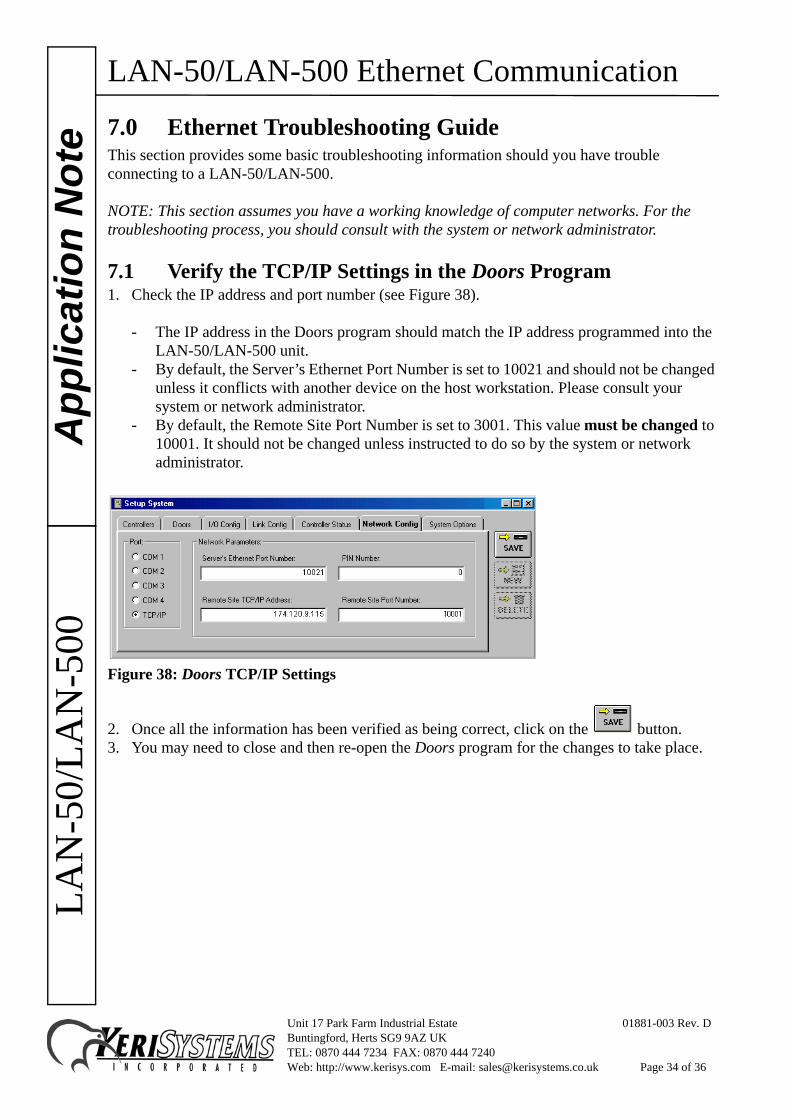
7.1 Verify the TCP/IP Settings in the Doors Program1. Check the IP address and port number (see Figure 38).
- The IP address in the Doors program should match the IP address programmed into the LAN-50/LAN-500 unit.
- By default, the Server’s Ethernet Port Number is set to 10021 and should not be changed unless it conflicts with another device on the host workstation. Please consult your system or network administrator.
- By default, the Remote Site Port Number is set to 3001. This value must be changed to 10001. It should not be changed unless instructed to do so by the system or network administrator.
Figure 38: Doors TCP/IP Settings
2. Once all the information has been verified as being correct, click on the button.3. You may need to close and then re-open the Doors program for the changes to take place.
Unit 17 Park Farm Industrial Estate 01881-003 Rev. DBuntingford, Herts SG9 9AZ UKTEL: 0870 444 7234 FAX: 0870 444 7240Web: http://www.kerisys.com E-mail: [email protected] Page 34 of 36
LAN-50/LAN-500 Ethernet CommunicationLA
N-50/LA
N-500
Application N
ote
7.2 Verify the LAN-50/LAN-500 Settings1. There are three ways to verify the LAN-50/LAN-500 settings. Refer to the LantronixReference Manual for detailed instructions on using each method.
- Telnet - channel 1 configuration commands- HTTP web browser utility - server properties, port properties
Review the displayed configuration for the LAN-50/LAN-500. Verify the LAN-50/LAN-500 settings per the instructions in Section 4.4 on page 24.
7.3 Verify the LAN-50/LAN-500 is Online1. Ping the IP address of the LAN-50/LAN-500. If the ping fails, that means a communication
connection cannot be made. Possible reasons are:
- There is no power to the LAN-50/LAN-500 unit.- The IP address was not programmed properly.- Another device on the network has that same IP address.- The workstation has not been granted access to that segment of the network.
Contact the system or network administrator to resolve these issues.
7.4 Contact Lantronix Technical Support1. If you continue to have problems connecting, detailed information is provided by Lantronix.
Please refer to the Lantronix Support web site at the following URL.
http://www.lantronix.com/support/
Table 2: Lantronix Part Description
Keri Systems, Inc. Lantronix Equivalent
LAN-50 UDS-10
LAN-500 Cobox Micro
Unit 17 Park Farm Industrial Estate 01881-003 Rev. DBuntingford, Herts SG9 9AZ UKTEL: 0870 444 7234 FAX: 0870 444 7240Web: http://www.kerisys.com E-mail: [email protected] Page 35 of 36
LAN-50/LAN-500 Ethernet CommunicationA
pplic
atio
n N
ote
LAN
-50/
LAN
-500
This page is intentionally left blank.
Unit 17 Park Farm Industrial Estate 01881-003 Rev. DBuntingford, Herts SG9 9AZ UKTEL: 0870 444 7234 FAX: 0870 444 7240Web: http://www.kerisys.com E-mail: [email protected] Page 36 of 36