Embed Size (px)
Citation preview
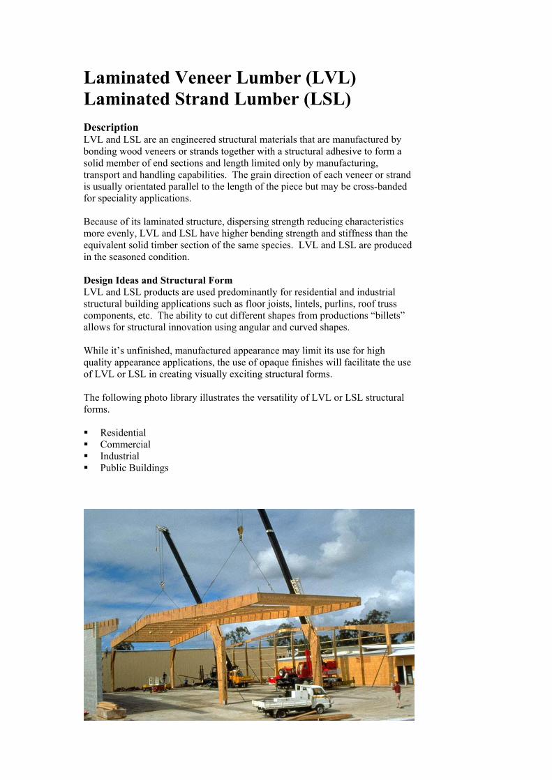
Laminated Veneer Lumber (LVL) Laminated Strand Lumber (LSL) Description LVL and LSL are an engineered structural materials that are manufactured by bonding wood veneers or strands together with a structural adhesive to form a solid member of end sections and length limited only by manufacturing, transport and handling capabilities. The grain direction of each veneer or strand is usually orientated parallel to the length of the piece but may be cross-banded for speciality applications. Because of its laminated structure, dispersing strength reducing characteristics more evenly, LVL and LSL have higher bending strength and stiffness than the equivalent solid timber section of the same species. LVL and LSL are produced in the seasoned condition. Design Ideas and Structural Form LVL and LSL products are used predominantly for residential and industrial structural building applications such as floor joists, lintels, purlins, roof truss components, etc. The ability to cut different shapes from productions “billets” allows for structural innovation using angular and curved shapes. While it’s unfinished, manufactured appearance may limit its use for high quality appearance applications, the use of opaque finishes will facilitate the use of LVL or LSL in creating visually exciting structural forms. The following photo library illustrates the versatility of LVL or LSL structural forms. Residential Commercial Industrial Public Buildings
(Project images still to come – Carter Holt Harvey)
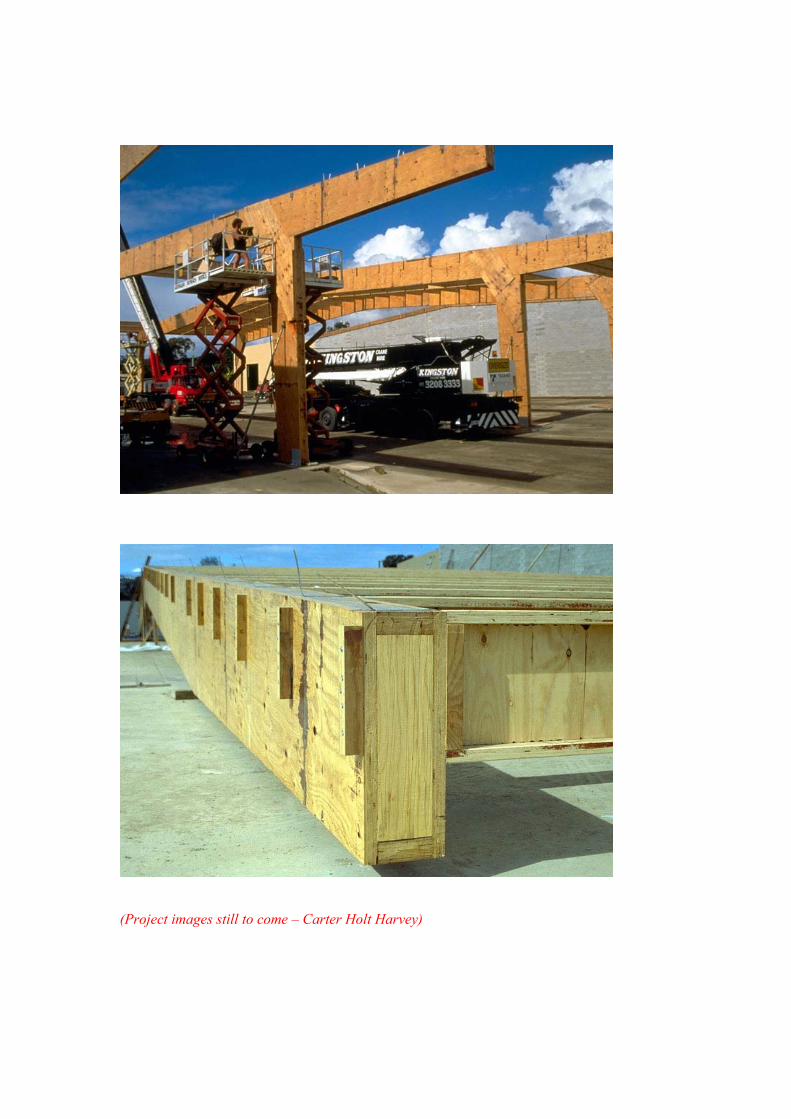
Shapes and Sizes LVL and LSL are usually manufactured as ‘billets’, 1.2 m wide for LVL and 2.4m wide for LSL, in a number of thicknesses (depending on the manufacturer) and in lengths up to 12 m or more from some manufacturers. Structural member sizes are re-sawn from the production billets in a range of standard widths, depending on the individual manufacturer. Other sizes are available to order. Curved shapes can be manufactured, provided the curved profile can be cut from the production “billets”. Commonly available stock widths and depths are as follows but advice should be sought from individual manufacturers prior to specification.
Depths 95, 130, 150, 170, 200, 240, 241, 300, 302, 356, 360, 400, 406, 457. Widths 36, 44, 45, 63, 68, 75, 89, 90 (Other widths can be created by laminating pieces together). Grades Each LVL or LSL manufacturer has designed and tested their products in accordance with AS/NZS 4063 Timber – Stress-graded – In-grade strength and stiffness evaluation to determine their design properties. This engineering data is available from the relevant manufacturer, together with span tables for common applications. Appearance LVL and LSL are generally not considered an appearance product, as glue lines are often quite visible. However, they may be coated with an opaque finish, after a light sanding if the unfinished appearance is not acceptable in visually exposed applications.
Performance Quality Control Each manufacturer maintains a quality control program to ensure manufacturing standards are maintained and design properties continue to meet the certified properties of the product. Some manufacturers participate in the Plywood Association of Australia process based Quality Control Program with products identified by the PAA “Product Certified” logos. Weather Exposure Short-term weather exposure during construction is not detrimental however LVL and LSL should not remain wet for long periods. LVL and LSL should not be used in weather exposed applications unless it is preservative treated and the top edge is weather protected and the member is painted or stained and the coating is maintained through the life of the project. Particular attention should be paid to sealing of end grain and in joints. Termite Resistance LVL and LSL are generally manufactured from Durability Class 4 (non-durable) softwood and therefore unless it is preservative treated, it is not termite resistant. LVL and LSL can be made termite resistant by preservative treatment to H2 level, usually with Light Organic Solvent Preservative. Fire Resistance Fire resistance of LVL and LSL depends on the section size of the member. LVL and LSL acts similarly to solid timber during exposure to fire, and has a slow and predictable charring rate, dependant on the timber species. When members are required to have a fire resistance rating, that can be calculated by subtracting a charred thickness from the original member size. Higher stresses can be used in combination with the reduced cross section. The fire resistance requirements can be calculated using the procedure given in AS 1720.4. Depending on the fire performance requirement, metal connectors may need special fire protection. Chemical Resistance Timber is often used where chemical deterioration eliminates use of other structural materials. Since wood substance is relatively inert chemically, under normal conditions it is not subject to chemical change or deterioration. It is resistant to most acids, rust and other corrosive agents. Typical uses in corrosive situations include hide curing complexes, fellmongerys, fertiliser storage and swimming pools. However, when exposed to strong oxidising agents, sulphides and alkalis, ‘pulping’ action (timber becomes very fibrous) may occur and therefore under these conditions specialist advice should be sought regarding the choice of timber species and adhesive.
Construction Practice LVL and LSL members are used similarly to seasoned softwood solid members except that LVL may be ripsawn through its depth without affecting its basic strength properties. The following construction practices apply. Handling, Storage and Protection Cutting Holes and Notches Joints and Connectors Weather Exposure
Handling, Storage and Protection Generally LVL and LSL should be handled as you would solid softwood timber. While some light handling damage may be acceptable for “hidden” or non-appearance structural applications, care should be taken to prevent damage to exposed edges where the member is to be visually exposed. For on-site storage of LVL and LSL, it should be supported on level bearers to keep it flat, well clear of the ground for good ventilation and stored undercover to keep it dry prior to installation, and protected from the sun to prevent cupping. LVL and LSL are not suitable for long term weather exposure unless preservative treated and finished with a protective coating. However, short-term exposure during the construction process does not affect LVL’s performance. Should construction be delayed, causing long term weather exposure, suitable protection shall be provided against sun and rain. Cutting Holes and Notches Generally, LVL and LSL can be worked similarly to solid softwood however cutting of holes and notches should comply with the appropriate manufacturers recommendations. These may require reinforcing around the hole or notch. Joints and Connectors Joining LVL and LSL are the same as joining solid timber. Traditional fasteners such as nails, screws and bolts can be used as well as proprietary metal connectors such as framing anchors, joist hangers etc. Concealed or exposed plates can also be used to secure butt connections such as in portal knee joints and joins in curved members. At supports it is essential that minimum bearing requirements be achieved. This may vary between different manufacturers. Important Note! Not all LVL and LSL are the same. Where a design is based on a particular size and brand of LVL and LSL, substitution with another brand should not be made without engineering advice.
Engineering Design The engineering design of LVL and LSL timber is quite similar to the design of sawn timber products:
• Straight (off-the-shelf) LVL and LSL products can be designed using many of the same philosophies used in designing sawn timber.
• LVL products in particular can be quite slender ( high depth to breadth ratio). This may require special attention to the design of beams to resist buckling.
• Where curved sections are to be cut from LVL, tension perpendicular to the grain can be induced under normal loadings. In these cases, “cross-banded” LVL offers better resistance to splitting perpendicular to grain.
Design of straight LVL members AS1720.1 section 8 is the primary reference for the structural design of LVL elements. A similar approach can be used for LSL although there is currently no Australian product standard for LSL or design rules for it. LVL which has been produced and stamped as complying with AS/NZS4357 can be designed using the provisions of section 8 of AS1720.1. LVL bending members The most common LVL element is the bending member. The normal strength limit state capacity equation is given in Clause 3.2.1.1 of AS1720.1, ( ) [ ]ZfkkkkkkM b'12119641φφ =
• Capacity factor (φ) can be found in Table 2.5, and has high values relative to sawn timber, because of the high levels of quality control required in the manufacture of structural LVL to AS/NZS4357.
• Duration of load (k1), and temperature factors (k6) are defined in Section 2 of AS1720.1 and are found in exactly the same way for LVL as for sawn timber.
• Moisture condition factor for LVL is different to that used for sawn timber. LVL is a seasoned product, and the k4 factor could be less than 1.0 if the equilibrium moisture content of the element in service is expected to be greater than 15%. AS1720.1 Clause 8.4.3 gives a linear relationship between k4 and the equilibrium moisture content (emc) if the emc is between 15% and 25%.
• Like glulam timber, the strength sharing factor (k9) for LVL is 1.0. This is appropriate as there is already a high level of strength sharing between the laminates in the LVL beam.
• For LVL beams, which can commonly be ripped to the design depth, there will be a size effect for bending. The size factor for bending (k11) of LVL is given in AS1720.1 in Clause 8.4.7, and is the same as the value used for F-grade sawn timber.
• The stability factor (k12) is found using the normal slenderness calculations given in AS1720.1 Clause 3.2. The material constant (ρ b) for LVL needs to be calculated separately for each product, as the strength and stiffness is defined only be the manufacturer. (There are no generic LVL or LSL grades.) The expression for calculating ρ b is given in AS1720.1 Clause 8.4.8.
• The bending strength of LVL or LSL materials that comply with AS/NZS4357 is published by the manufacturer. This is the only source for that information.
• With LVL, there is –0 tolerance on sizes, so the design dimensions are the nominal dimensions. The nominal dimensions can be used to find the section modulus (Z).
LVL sections can be quite slender (a high d/b ratio), so care should be made to provide torsional stability to the member at its supports. This can be achieved with blocking pieces between members or a strap over the top of the beam. Slenderness leading to the k12 factor should be carefully found with due attention to the detailing required to provide the restraint assumed. The strength limit state shear capacity equation is given in Clause 3.2.5 of AS1720.1, ( ) [ ]ss AfkkkkV '11641φφ =
• Capacity factor (φ), duration of load factor (k1), and temperature factors (k6) are all found in the normal way using Section 2 of AS1720.1
• Moisture condition factor for LVL is different to that used for sawn timber. The moisture condition factor, k4 is given in AS1720.1 Clause 8.4.3. Note that the factor used for shear is different to the factor used for bending.
• For LVL beams, the size factor for shear (k11) is 1.0 from AS1720.1 Clause 8.4.7. This is common with the size factor for shear in most other timber materials.
• The shear strength of LVL material is only available as published by the manufacturer. There are no generic LVL grades.
• Nominal design dimensions should be used to find the shear area (As). For timber, the shear area is 2/3 the cross sectional area (Clause 3.2.5 of AS1720.1).
As with other timber beams, the strength limit state bearing capacity of timber is only a function of the species of the timber, the grade or manufacture of the material is not important. The strength limit state bearing capacity equation is given in Clause 3.2.6 of AS1720.1, ( ) [ ]
sppp AfkkkkN '7641φφ = - applicable for bearing of beams.
• Capacity factor (φ), duration of load factor (k1), partial seasoning factor (k4) and temperature factors (k6) are all found in the normal way using Section 2 of AS1720.1 (The capacity factor for all timber materials is the same – it is independent of grade or method of production.)
• Moisture condition factor for LVL is different to that used for sawn timber. The moisture condition factor, k4 is given in AS1720.1 Clause 8.4.3, but bearing is not included. As bearing is a compression phenomenon, it is prudent to use the value tabulated for bending and compression.
• (k7) is a factor for the length and position of bearing. It is defined in Clause 2.4.4 of AS1720.1 and is used in the same way for all timber materials.
• The bearing strength of the LVL material (and all other timber elements) is only a function of the species of the bearing layers. Table 2.1 or Table 2.2 in AS1720.1 is used to define a strength group to the species, and the bearing strength of the timber is given in Table 2.3(A) in AS1720.1.
• Minimum design dimensions (after allowing for tolerances) should be used to find the bearing area (Ap).
Deflections of LVL members can be calculated using the similar techniques to those used for other timber structural beams. The main exception for LVL is the inclusion of a term that corrects deflections for moisture content:
• As wood increases in moisture, it becomes more flexible. The LVL section of the standard is the only part that makes allowance for this.
• The Modulus of Elasticity (E) used to find the deflections should be corrected for non-elastic behaviour by multiplication by j6.
• The j6 factor is given in AS1720.1 Clause 8.4.3. It is 1.0 for design environments in which the emc remains at or below 15%, and for higher moisture contents, the j6 factor is less than 1. This gives a lower Modulus of Elasticity and hence a greater deflection. This is still an elastic deflection, and the j2 factor should be used to correct it for non-elastic behaviour due to creep.
• The duration of load factor j2 is the same factor used for other timber elements.
• The E value for LVL is published by the manufacturer. There are no generic LVL grades.
• Vibrations under repetitive loads may change due to the moisture condition factor, so j6 should be used on all loads regardless of their duration or whether it is an absolute or relative deflection that is required.
LVL compression members LVL compression members can be used in trusses, in composite cross section columns, in portal frames or in reticulated arches or domes. The normal strength limit state capacity equation is given in Clause 3.3.1.1 of AS1720.1, ( ) [ ]ccc AfkkkkkN '1211641φφ =
• Capacity factor (φ) can be found in Table 2.5, and has high values relative to sawn timber, because of the high levels of quality control required in the manufacture of structural LVL to AS/NZS4357.
• Duration of load (k1), and temperature factors (k6) are defined in Section 2 of AS1720.1 and are found in exactly the same way for LVL as for sawn timber.
• Moisture condition factor for LVL is different to that used for sawn timber. The moisture condition factor, k4 is given in AS1720.1 Clause 8.4.3. Note that the factor used for compression is the same as the factor used for bending.
• For LVL compression members, the size factor for bending (k11) is 1.0 (in this case, this is the same as the value for F-graded products).
• The stability factor (k12) is found using the normal slenderness calculations given in AS1720.1 Clause 3.3.3. The material constant (ρ c) for LVL is calculated using the expression given in AS1720.1 Clause 8.4.8 and the properties of the material as published by the manufacturer.
• The compression strength of the LVL material is only available as published by the manufacturer. There are no generic LVL grades.
• Nominal dimensions should be used to find the compression area (Ac). The minimum design dimensions are the same as the nominal dimensions as there is 0 negative tolerance for LVL.
Relative to many timber products, LVL has quite a high strength to stiffness ratio. This means that it is often slenderness and buckling that is limiting the performance of compression members. The relatively low thickness of standard LVL sections (compared with available depths) means that often it is minor axis
buckling that will limit its performance. Restraint of minor axis buckling should be considered as an option to enhance performance. LVL elements can be used as top and bottom flanges of I beams or box beams. In this role, their function is essentially a compression and tension element, with buckling about the minor axis constrained. Buckling about the major axis must still be considered. Restraint against major axis buckling will be provided by crossing members such as flooring, joists, battens or purlins. LVL tension members LVL tension members are really only found in trusses, I beams or box beams. Designers may have to calculate tension capacity to check compression members that may experience load reversal, or for combined actions (such as portal frames). The normal strength limit state capacity equation is given in Clause 3.4.1 of AS1720.1, ( ) [ ]ttt AfkkkkN '11641φφ =
• Capacity factor (φ) can be found in Table 2.5, and has high values relative to sawn timber, because of the high levels of quality control required in the manufacture of structural LVL to AS/NZS4357.
• Duration of load (k1) and temperature factors (k6) are defined in Section 2 of AS1720.1 and are found in exactly the same way for LVL as for sawn timber.
• Moisture condition factor for LVL is different to that used for sawn timber. The moisture condition factor, k4 is given in AS1720.1 Clause 8.4.3. Note that the factor used for tension is the same as the factor used for shear, but different from the factor used for compression and bending.
• For LVL beams, which can be ripped to size out of sheets, the size factor for tension (k11) is given in Clause 8.4.7 of AS1720.1. The value found is the same one for F-graded timber products. This is likely to be quite conservative, but because tensile failures are brittle, that is wise.
• The tension strength of the LVL material is only published by the manufacturer. There are no generic LVL grades in AS1720.1.
• Nominal dimensions should be used to find the tension area (At). The tension area is the minimum net cross sectional area. For large or complex connections, this may involve calculation of area of cross section removed for large connectors (such as split rings or shear plates), bolts or dowels, and any embedded steel plates.
Design of complex, curved or tapered LVL members LVL and LSL sections are large prismatic pieces that are very straight. If curved structural elements are required, then they must be made by cutting a curved shape from larger pieces. Likewise tapered or double-tapered members can be cut from larger pieces. Curved and tapered structural elements must also satisfy other provisions in AS1720.1 Appendix E12 and Appendix E13. Cutting tapered or curved shapes exposes at least one edge to having flexural stresses at an angle to the grain. This can lead to a lowering of strength and stiffness at that edge. The calculations to model this behaviour are given in Clause E12 in AS1720.1. They can be applied without modification to LVL.
In addition, the curvature of the centre-line causes tension perpendicular to the grain at the centre-line where bending moments cause the curve to open. Calculations to model these behaviours are given in Clause E13 in AS1720.1 In the case of cutting to produce curves rather than bending laminates, kr should be taken as 1.0. The serviceability calculations of curved or tapered members follow a similar methodology to those for straight members, though some adjustment should be made for the slope of grain at the edge of tapered members. This can be approximated by using Hankinson’s formula and by assuming that the MoE of wood perpendicular to grain is about 1/50 the value of MoE parallel to grain. Hankinson’s formula is:
θθθ 22 cossin p
p
EEEE
E+
=l
l
with El MoE parallel to grain (as given by the manufacturer) Ep MoE perpendicular to grain (estimated as 1/50 to 1/30 El) θ angle of slope of grain (taper angle at the edge) Cross-banded LVL Cross banded LVL is manufactured by including one or two laminations in the cross section with the grain running perpendicular to the longitudinal axis of the sheet. This product has advantages when used in specific applications:
• Short span deep beams produce very high shear stresses compared with the flexural stresses. The cross-banding removes some of the wood fibre that contributes to bending strength and stiffness and substitutes it with fibre that contributes to shear strength.
• Elements that are curve or taper cut from sheets have slope of grain that is at an angle to the flexural stresses. This would normally tend to cause splitting along the grain lines, but the cross-bands provide fibre with strength in the direction that will minimise those splits.
• Elements that are used in an environment that may have changeable moisture content may tend to split on wetting and drying. The cross-banding will reduce the tendency of these elements to split.
Cross-banded LVL has a different set of properties to LVL with all plies parallel to the longitudinal axis. The shear strength is higher and the tensile strength perpendicular to the grain is also considerably higher. The flexural strength is marginally lower and the MoE parallel to grain is also a little lower. Manufacturers Information Product specific information including member span tables is available from individual LVL manufacturers.