Embed Size (px)
Citation preview
LAMINATE FLOORING
SPECIFICATIONS AND TEST METHODS
NALFA Standards Publication LF 01-2008
LAMINATE FLOORING Published by North American Laminate Flooring Association © 2008 by North American Laminate Flooring Association
North American Laminate Flooring Association

© 2008, The North American Laminate Flooring Association, all rights reserved. The [attached/aforementioned] document is the property of "NALFA"; it represents the consensus efforts of that Organization and its membership; which is comprised of manufacturers, distributors, materials providers, and ancillary entities. NALFA bears no responsibility and disclaims all liability for information/material contained in the Document which may subsequently be changed.
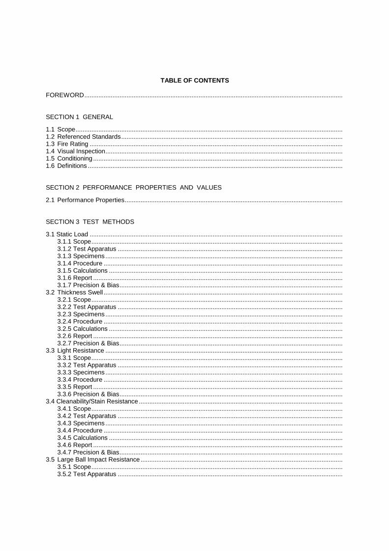
TABLE OF CONTENTS
FOREWORD................................................................................................................................................... SECTION 1 GENERAL
1.1 Scope........................................................................................................................................................ 1.2 Referenced Standards.............................................................................................................................. 1.3 Fire Rating ................................................................................................................................................ 1.4 Visual Inspection....................................................................................................................................... 1.5 Conditioning .............................................................................................................................................. 1.6 Definitions ................................................................................................................................................. SECTION 2 PERFORMANCE PROPERTIES AND VALUES
2.1 Performance Properties............................................................................................................................ SECTION 3 TEST METHODS
3.1 Static Load ................................................................................................................................................ 3.1.1 Scope............................................................................................................................................... 3.1.2 Test Apparatus ................................................................................................................................ 3.1.3 Specimens ....................................................................................................................................... 3.1.4 Procedure ........................................................................................................................................ 3.1.5 Calculations ..................................................................................................................................... 3.1.6 Report .............................................................................................................................................. 3.1.7 Precision & Bias............................................................................................................................... 3.2 Thickness Swell ........................................................................................................................................ 3.2.1 Scope............................................................................................................................................... 3.2.2 Test Apparatus ................................................................................................................................ 3.2.3 Specimens ....................................................................................................................................... 3.2.4 Procedure ........................................................................................................................................ 3.2.5 Calculations ..................................................................................................................................... 3.2.6 Report .............................................................................................................................................. 3.2.7 Precision & Bias............................................................................................................................... 3.3 Light Resistance ....................................................................................................................................... 3.3.1 Scope............................................................................................................................................... 3.3.2 Test Apparatus ................................................................................................................................ 3.3.3 Specimens ....................................................................................................................................... 3.3.4 Procedure ........................................................................................................................................ 3.3.5 Report .............................................................................................................................................. 3.3.6 Precision & Bias............................................................................................................................... 3.4 Cleanability/Stain Resistance .................................................................................................................... 3.4.1 Scope............................................................................................................................................... 3.4.2 Test Apparatus ................................................................................................................................ 3.4.3 Specimens ....................................................................................................................................... 3.4.4 Procedure ........................................................................................................................................ 3.4.5 Calculations ..................................................................................................................................... 3.4.6 Report .............................................................................................................................................. 3.4.7 Precision & Bias............................................................................................................................... 3.5 Large Ball Impact Resistance ................................................................................................................... 3.5.1 Scope............................................................................................................................................... 3.5.2 Test Apparatus ................................................................................................................................

3.5.3 Specimens ....................................................................................................................................... 3.5.4 Procedure ........................................................................................................................................ 3.5.5 Report .............................................................................................................................................. 3.5.6 Precision & Bias............................................................................................................................... 3.6 Small Ball Impact Resistance ................................................................................................................... 3.6.1 Scope............................................................................................................................................... 3.6.2 Test Apparatus ................................................................................................................................ 3.6.3 Specimens ....................................................................................................................................... 3.6.4 Procedure ........................................................................................................................................ 3.6.5 Report .............................................................................................................................................. 3.6.6 Precision & Bias............................................................................................................................... 3.7 Wear Resistance ...................................................................................................................................... 3.7.1 Scope............................................................................................................................................... 3.7.2 Test Apparatus ................................................................................................................................ 3.7.3 Specimens ....................................................................................................................................... 3.7.4 Calibration........................................................................................................................................ 3.7.5 Procedure ........................................................................................................................................ 3.7.6 Calculations ..................................................................................................................................... 3.7.7 Report .............................................................................................................................................. 3.7.8 Precision & Bias............................................................................................................................... 3.8 Dimensional Tolerance............................................................................................................................. 3.8.1 Scope............................................................................................................................................... 3.8.2 Definitions ........................................................................................................................................ 3.8.3 Test Apparatus ................................................................................................................................ 3.8.4 Specimens ....................................................................................................................................... 3.8.5 Procedure ........................................................................................................................................ 3.8.6 Report .............................................................................................................................................. 3.8.7 Precision & Bias............................................................................................................................... 3.9 Castor Chair Resistance ........................................................................................................................... 3.9.1 Scope............................................................................................................................................... 3.9.2 Test Apparatus ................................................................................................................................ 3.9.3 Specimens ....................................................................................................................................... 3.9.4 Procedure ........................................................................................................................................ 3.9.5 Report .............................................................................................................................................. 3.9.6 Precision & Bias............................................................................................................................... 3.10 Surface Bond…………………………………………………………………………………………………….. 3.10.1 Scope………………………………………………………………………………………………….…… 3.10.2 Test Apparatus……………………………………………………………………………………….…… 3.10.3 Specimens………………………………………………………………………………………….……... 3.10.4 Procedure…………………………………………………………………………………………………. 3.10.5 Calculations……………………………………………………………………………………………….. 3.10.6 Report……………………………………………………………………………………………………… 3.10.7 Precision & Bias………………………………………………………………………………………….. SECTION 4 THIRD PARTY CERTIFICATION
4.1 Compliance............................................................................................................................................... 4.2 Certification............................................................................................................................................... 4.3 Effective Date ........................................................................................................................................... APPENDIX A................................................................................................................................................... APPENDIX B................................................................................................................................................... APPENDIX C................................................................................................................................................... APPENDIX D................................................................................................................................................... APPENDIX E……………………………………………………………………………………………………………

Foreword The North American Laminate Flooring Association has prepared this Standards Publication for use by manufacturers, suppliers, distributors, dealers, and consumers of laminate flooring. The performance values and test methods presented have been related as closely as possible to end-use applications, and consumer needs have been considered throughout. The purpose of this Standards Publication is to provide tiered, minimum performance set of requirements for laminate flooring using standard test methods. Such performance requirements include but are not limited to: static load, thickness swell, impact resistance, light resistance, cleanability/stain resistance, wear resistance, dimensional tolerances, surface bond and castor chair resistance. The requirement of this standard applies to laminate flooring upon manufacturer’s completion and proper storage until first placed into service. For all products which utilize an attached underlayment, they shall be tested with the attached back for any test which specifies use of an underlayment. For tests where no underlayment is required, i.e. thickness swell, static load, etc. the laminate shall be tested by itself. Either the attached backer must be removed or the product supplied separately in both attached and unattached format for testing purposes. If no underlayment is supplied when the product is submitted for testing, where underlayment is required, a closed-cell foam with a thickness of 2.0mm +/- 0.5mm (0.080in +/- 0.02in) and a density of 35kg/cu-m +/- 5 kg/cu-m (2.2 lb/cu-ft +/- 0.3lb/cu-ft) or equivalent will be used. The procedures and criteria within this specification provide evaluation guidance regarding laminate products to meet various performance requirements. As testing capability improves, it is recognized that equivalent test methods may be considered, i.e. for properties such as measuring geometrical dimensions, squareness, etc. provided they can demonstrate improvement in accuracy of measurement and or reduced variation, without significant bias. The Technical Committee works closely with trade organizations, consumers, manufacturers, and appropriate government agencies in the periodic review and revision of these standards. In this 2008 publication for Laminate Flooring, effort has been made to relate this Standard closely to the expected performance in application. During laminate flooring installation, the fabrication method and technique employed will have a definite bearing on product performance and service. Consult individual laminate flooring manufacturers for specific installation criteria. Metric values for the test procedures and performance standards are regarded as the standard. This standard is periodically reviewed by the Technical Committee for any revisions necessary to keep them up to date with advancing technology. Proposed or recommended revisions should be submitted to:
Technical Director North American Laminate Flooring Association
Webster, Chamberlain, & Bean 1747 Pennsylvania Avenue, NW Suite 1000
Washington, DC 20006 (202) 785-9500
Section 1 GENERAL
1.1 SCOPE
This product standard shall apply to the performance of laminate flooring. The standard will be useful in guiding manufacturers and educating consumers regarding minimum expectations or requirements of laminate flooring, by category segment: Residential, Light Commercial, Commercial or Heavy Commercial.
The precision of all the specified tests methods is not known. For those methods where interlaboratory testing has been completed, an appropriate precision statement has been made. When the interlaboratory data becomes available for the remaining test methods, the precision statements for those methods will be added in subsequent revisions.
1.2 REFERENCED STANDARDS
In this publication, reference is made to the standards listed below. Copies are available from the indicated sources:
Swedish Standards Institution
Box 490 44 SE-100 28 Stockholm, Sweden
SIS 21824 I. P. Poster
Technical Association of the Pulp & Paper Industry
Technology Park P. O. Box 105113
Atlanta, GA 30348 (770) 446-1400
TAPPI T-564 Size Estimation Chart
1.3 FIRE RATING
Appendix A lists specific test methods which are typically used in determining the fire ratings which have been established by code–developing and specifying agencies such as National Fire Protection Association, International Code Council, and other local, state, and federal agencies. When fire ratings are required by specific code, the manufacturer of the product being specified should be consulted.
1.4 VISUAL INSPECTION
The inspector shall have normal sight and color vision, corrected if necessary. No magnification shall be used when viewing the specimens.
1.5 CONDITIONING
For the purpose of test method standardization, it is recommended that a laminate flooring sample or specimen prior to evaluation shall be conditioned to constant weight (less than 0.1% deviation per 24 hours) in a conditioning chamber unless denoted otherwise in the method. The chamber shall be maintained at temperature of 23oC + 3oC (73oF + 5oF) and 50% + 5% relative humidity. If there is any departure from this recommended conditioning, it shall be stated in the test report.

1.6 DEFINITIONS 1.6.1 Backer: A material bonded to the back of the substrate. 1.6.2 Décor Layer: The layer of laminate flooring providing visual aesthetic properties. 1.6.3 Laminate Flooring: A rigid floor covering with a surface layer consisting of one or more thin
sheets of a fibrous material (usually paper), impregnated with aminoplastic thermosetting resins (usually melamine), pressed or bonded on a substrate, normally finished with a backer.
1.6.4 Substrate: The core material of the laminate flooring.


NALFA/ANSI LF-01-2008 PERFORMANCE PROPERTIES AND VALUES
2.1 PERFORMANCE PROPERTIES
Table 2-1 Performance Properties and Values
MINIMUM PERFORMANCE VALUES
Usage Level
Residential
Light Commercial
Commercial Heavy Commercial
Certification Level
1 2
3 4
TEST METHOD
PROPERTY
3.1 Static Load > 6 MPa (870 psi) > 6 MPa (870 psi) > 8 MPa (1160 psi) > 8 MPa (1160 psi)
3.2
Thickness
Swell
< 18 %
< 16%
< 16%
< 12%
3.3
Light Resistance
No More than Slight Effect
No More than Slight Effect
No More than Slight Effect
No More than slight Effect
3.4
Cleanability/
Stain Resistance
Score < 20
No More Than Slight Effect
Score < 20
No More Than Slight Effect
Score < 20
No More Than Slight Effect
Score < 20
No More Than Slight Effect
3.5
Large Ball
Impact Resistance
> 800 mm (31.5 in)
> 1000 mm (39.4 in)
> 1200 mm (47.3 in.)
> 1400 mm (55.1 in)
3.6
Small Ball
Impact Resistance
> 200 mm (7.9 in)
> 200 mm (7.9 in)
> 350 mm (13.8 in.)
> 500 mm (19.7 in)
3.7
Wear
Resistance
IP ≥ 1500 cycles
IP ≥ 2000 cycles
IP ≥ 4000 cycles
IP ≥ 6000 cycles
Length: 0.50 mm (0.020 in) Length: 0.50 mm (0.020 in) Length: 0.50 mm (0.020 in) Length: 0.50 mm (0.020 in)
Width: 0.20 mm (0.008 in) Width: 0.20 mm (0.008 in) Width: 0.20 mm (0.008 in) Width: 0.20 mm (0.008 in)
Thickness: 0.50 mm (0.020 in)
Thickness: 0.50 mm (0.020 in)
Thickness: 0.50 mm (0.020 in)
Thickness: 0.50 mm (0.020 in)
Squareness: 0.20 mm (0.008 in)
Squareness: 0.20 mm (0.008 in)
Squareness: 0.20 mm (0.008 in)
Squareness: 0.20 mm (0.008 in)
3.8
Dimensional Tolerances
Straightness: 0.30 mm
(0.012 in) Straightness: 0.30 mm
(0.012 in) Straightness: 0.30 mm
(0.012 in) Straightness: 0.30 mm
(0.012 in)
3.9
Castor Chair Resistance
25000 cycles No Effect
25000 cycles No Effect
25000 cycles No Effect
35000 cycles
No Effect
3.10
Surface Bonding
1 N/mm² 1.25 N/mm² 1.25 N/mm² 1.5 N/mm²
Section 3 TEST METHODS
3.1 STATIC LOAD 3.1.1 Scope
This test measures the ability of laminate flooring to resist residual indentation resulting from a static load.
3.1.2 Test Apparatus
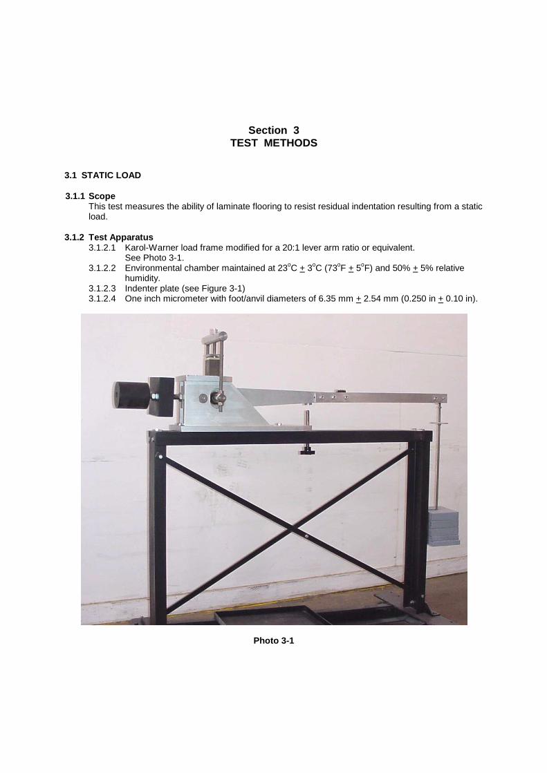
3.1.2.1 Karol-Warner load frame modified for a 20:1 lever arm ratio or equivalent. See Photo 3-1.
3.1.2.2 Environmental chamber maintained at 23oC + 3oC (73oF + 5oF) and 50% + 5% relative humidity.
3.1.2.3 Indenter plate (see Figure 3-1) 3.1.2.4 One inch micrometer with foot/anvil diameters of 6.35 mm + 2.54 mm (0.250 in + 0.10 in).
Photo 3-1
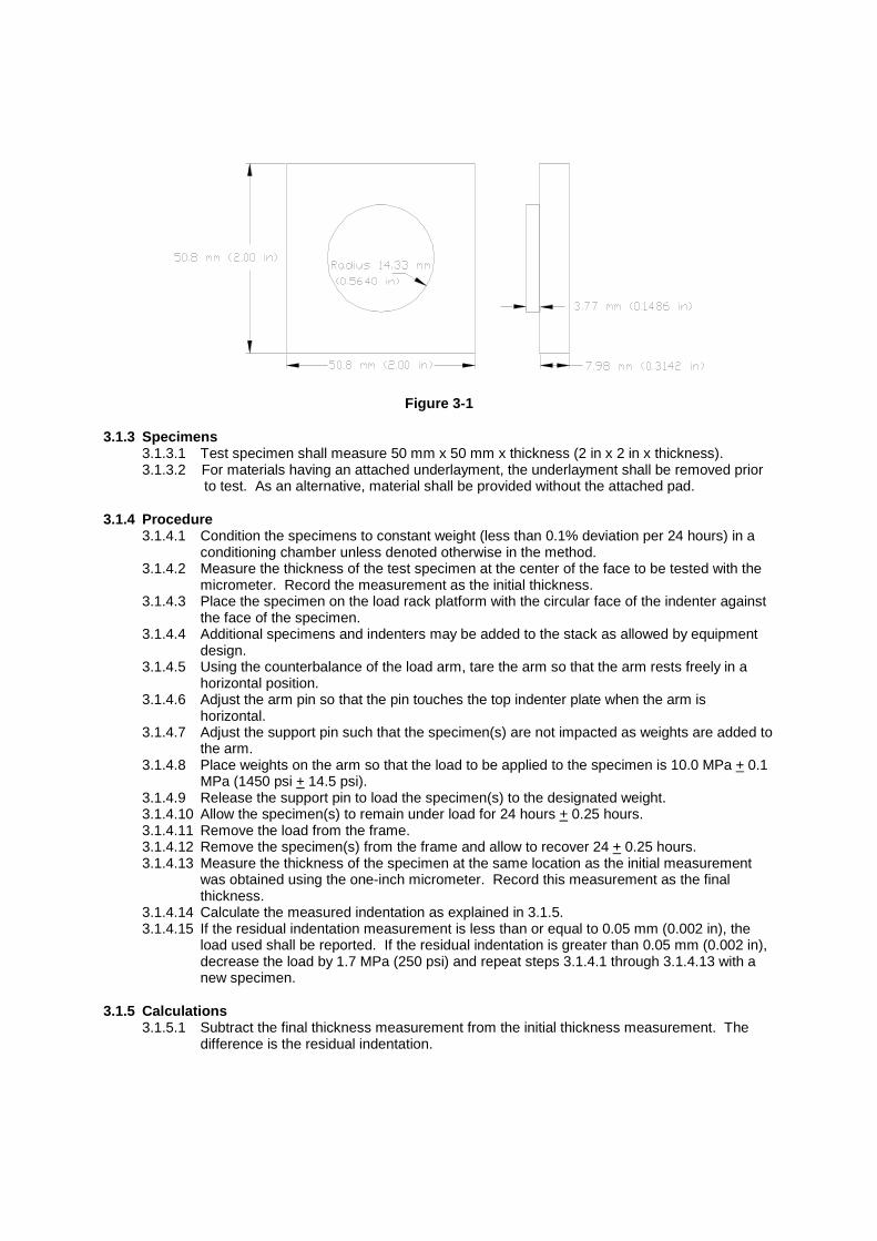
Figure 3-1 3.1.3 Specimens
3.1.3.1 Test specimen shall measure 50 mm x 50 mm x thickness (2 in x 2 in x thickness). 3.1.3.2 For materials having an attached underlayment, the underlayment shall be removed prior to test. As an alternative, material shall be provided without the attached pad.
3.1.4 Procedure
3.1.4.1 Condition the specimens to constant weight (less than 0.1% deviation per 24 hours) in a conditioning chamber unless denoted otherwise in the method.
3.1.4.2 Measure the thickness of the test specimen at the center of the face to be tested with the micrometer. Record the measurement as the initial thickness.
3.1.4.3 Place the specimen on the load rack platform with the circular face of the indenter against the face of the specimen.
3.1.4.4 Additional specimens and indenters may be added to the stack as allowed by equipment design.
3.1.4.5 Using the counterbalance of the load arm, tare the arm so that the arm rests freely in a horizontal position.
3.1.4.6 Adjust the arm pin so that the pin touches the top indenter plate when the arm is horizontal.
3.1.4.7 Adjust the support pin such that the specimen(s) are not impacted as weights are added to the arm.
3.1.4.8 Place weights on the arm so that the load to be applied to the specimen is 10.0 MPa + 0.1 MPa (1450 psi + 14.5 psi).
3.1.4.9 Release the support pin to load the specimen(s) to the designated weight. 3.1.4.10 Allow the specimen(s) to remain under load for 24 hours + 0.25 hours. 3.1.4.11 Remove the load from the frame. 3.1.4.12 Remove the specimen(s) from the frame and allow to recover 24 + 0.25 hours. 3.1.4.13 Measure the thickness of the specimen at the same location as the initial measurement
was obtained using the one-inch micrometer. Record this measurement as the final thickness.
3.1.4.14 Calculate the measured indentation as explained in 3.1.5. 3.1.4.15 If the residual indentation measurement is less than or equal to 0.05 mm (0.002 in), the
load used shall be reported. If the residual indentation is greater than 0.05 mm (0.002 in), decrease the load by 1.7 MPa (250 psi) and repeat steps 3.1.4.1 through 3.1.4.13 with a new specimen.
3.1.5 Calculations
3.1.5.1 Subtract the final thickness measurement from the initial thickness measurement. The difference is the residual indentation.

3.1.6 Report The test report shall include the following: 3.1.6.1 Reference to this standard. 3.1.6.2 Description of the material under test. 3.1.6.3 The value of the maximum load applied which produces residual indentation of less 0.05
mm (0.002 in). 3.1.6.4 Any deviation from the specified test method. 3.1.6.5 Date of the test.
3.1.7 Precision & Bias
3.1.7.1 Test method precision and bias have not been established at this time. Repeatability measurements for product thickness under no load gave a repeatability sigma of 0.009 mm (0.00035 in). Additional work is under consideration by the NALFA Technical Committee.
3.2 THICKNESS SWELL 3.2.1 Scope
This test measures the ability of laminate flooring to resist increase in thickness after being exposed to water.
3.2.2 Test Apparatus
3.2.2.1 Pan or other suitable apparatus for submerging specimens. 3.2.2.2 One inch micrometer with foot/anvil diameters of 6.35 mm + 2.54 mm (0.250 in + 0.10 in). 3.2.2.3 Distilled or deionized water maintained at 20oC + 1oC (68oF + 2oF). 3.2.2.4 Ruler.
3.2.3 Specimens
3.2.3.1 A test specimen shall measure 150 mm x 150 mm x thickness (6 in x 6 in x thickness). Where material is less than 150 mm (6 inches) in one dimension of the face, select the specimen at the nominal width and trim all four sides to obtain smooth edges. Two specimens shall be collected for each test. Each specimen shall be taken from opposite ends of a tile. Specimen edges shall be smooth and squarely trimmed. They shall not be preconditioned.
3.2.3.2 For materials having an attached underlayment, the underlayment shall be removed prior to test. As an alternative, material shall be provided without the attached pad.
3.2.4 Procedure
3.2.4.1 Measure the thickness of each test specimen at the edge of the middle point of the four sides (see Figure 3-2). Record the measurements as the initial thickness.
3.2.4.2 Submerge each specimen under the water so that the top face of each specimen is 25.4 mm + 2.54 mm (1 in + 0.1 in) from the surface of the water. Specimen faces shall not rest against a flat surface as this impedes water circulation and absorption.
3.2.4.3 Specimens shall remain submerged for a total of 24 hours + 0.25 hours. 3.2.4.4 At the end of the 24 hours, remove the specimens from the water. 3.2.4.5 Repeat the measurements outlined in step 3.2.4.1 within 15 minutes of removal from the
water. Record the measurements as the final thickness.
a
b
c
d
measurement locations
sample
micrometer anvil
sample edge
Relationship of micrometer anvil to sample edge

Figure 3-2 3.2.5 Calculations
3.2.5.1 Express the thickness swell as the average percentage increase in thickness. It is calculated for each edge as:
((final thickness – initial thickness) / initial thickness) x 100
3.2.5.2 The eight percentage results are then averaged to obtain the thickness swell result.
3.2.6 Report
3.2.6.1 Reference to this standard. 3.2.6.2 Description of the material under test. 3.2.6.3 The average of the thickness measurements. 3.2.6.4 The thickness swell value. 3.2.6.5 Any deviation from the specified test method. 3.2.6.6 Date of the test.
3.2.7 Precision & Bias
3.2.7.1 Table 3-1 is based on interlaboratory studies conducted in 1999 involving three replicate tests of nine materials tested by nine laboratories.
Material Mean Sr SR Ir IR
A 5.32% 0.30% 0.91% 0.84% 2.57% B 6.87% 0.33% 1.08% 0.94% 3.05% C 8.05% 0.32% 1.18% 0.89% 3.34% D 8.08% 0.30% 1.87% 0.83% 5.26% E 10.79% 0.54% 2.76% 1.53% 7.79% F 11.77% 0.41% 1.38% 1.15% 3.90% G 13.53% 0.57% 3.01% 1.61% 8.49% H 14.55% 0.49% 2.23% 1.38% 6.28% I 14.68% 0.47% 2.87% 1.31% 8.10%
Table 3-1
3.2.7.2 In Table 3-1, for the materials indicated:
3.2.7.2.1 Mean is the average of test results for all replicates from all labs. 3.2.7.2.2 Sr is the within-laboratory standard deviation of the mean and Ir = 2.83Sr (see
3.2.7.2.4 for application of Ir). 3.2.7.2.3 SR is the between-laboratory standard deviation of the mean and IR = 2.83SR (see
3.2.7.2.5 for application of IR). 3.2.7.2.4 Repeatability – In comparing two mean values for the same material obtained by
the same operator using the same equipment on the same day, the means should be judged not equivalent if they differ by more than the Ir value for that material and condition.
3.2.7.2.5 Reproducibility – In comparing two mean values for the same material obtained by different operators using different equipment on different days, the means should be judged not equivalent if they differ by more than the IR value for that material and condition. (This applies between different laboratories or between different equipment within the same laboratory.)
3.2.7.3 The judgments per 3.2.7.2.4 and 3.2.7.2.5 will have an approximate 95% (0.95) probability of being correct.
3.2.7.4 Other materials may give somewhat different results.

3.3 LIGHT RESISTANCE 3.3.1 Scope
This test measures the ability of laminate flooring to retain its color when exposed to a light source having a frequency range approximating sunlight through window glass. It is not intended to show the resistance to continuous exposure to outdoor weathering conditions.
3.3.2 Test Apparatus
3.3.2.1 Xenon-arc light source capable of providing electromagnetic energy approximating sunlight with a spectral bandpass of approximately 280 nm to 800 nm with filtering appropriate to simulate sunlight through a window.
3.3.2.2 Environmental Chamber maintained at 23oC + 3oC (73oF + 5oF) and relative humidity of 50% + 5%.
3.3.2.3 Overhead lighting consisting of cool white fluorescent light with the bulbs positioned parallel to the line of sight and providing an intensity of 800 lux to 1100 lux (75 foot-candles to 100 foot-candles) at the specimen surface when examined.
3.3.3 Specimens
3.3.3.1 The test specimen shall be of the size required by the sample holder of the Xenon-arc test apparatus.
3.3.4 Procedure
3.3.4.1 Condition the specimen for at least 48 hours prior to the test at a temperature of 23oC + 3oC (73oF + 5oF) and relative humidity of 50% + 5%.
3.3.4.2 Mount the specimen in a masked holder such that approximately ½ of the sample face to be tested is covered and the other half is exposed to the light source.
3.3.4.3 Operating set points for the exposure shall be as follows: 3.3.4.3.1 Black Panel Temperature 70oC + 3oC (158oF + 5oF) 3.3.4.3.2 Dry Bulb Temperature* 50oC + 3oC (122oF + 5oF) 3.3.4.3.3Wet Bulb Temperature 39oC + 1oC (102oF + 2oF) to maintain 50% (+
5%) Relative Humidity 3.3.4.3.4 Conditioning Water 20oC + 3oC (68oF + 5oF) 3.3.4.3.5 Duration of Exposure 100 hours + 0.5 hour 3.3.4.3.6 Calibration wavelength 420 nm 3.3.4.3.7 Rate of Irradiance 1.10 W/m2 + 0.03 W/m2 3.3.4.3.8 Total Irradiance 396 kJ/m2 + 2.00 kJ/m2 3.3.4.3.9 Automatic control of power to the light source to maintain a constant irradiance
level and accommodate for aging effect of light sources and solarization of filters. *Note: The Black Panel Temperature is the primary controlled temperature and the Dry
Bulb Temperature is secondary control. 3.3.4.4 Expose the specimen to the light source as outlined in 3.3.4.3. 3.3.4.5 At the conclusion of the exposure period, remove the specimen from the holder and allow
to recover for 24 hours + 1 hour without exposure to light at a temperature of 23oC + 3oC (73oF + 5oF) and relative humidity of 50% + 5%.
3.3.4.6 At the conclusion of the recovery period, examine the specimen by placing it, without pre-inspection, on a horizontal surface having the illumination as outlined in 3.3.2.3 and then viewing the specimen at an eye-to-specimen distance of approximately 750 mm to 900 mm (30 in to 36 in) and at an angle of approximately 45o to 75o from the horizontal plane. The specimen shall be rotated in the horizontal plane and viewed from all directions. Light sources other than that outlined in 3.3.2.3, which can accentuate or minimize effects, shall be avoided.
3.3.4.7 Grade the specimen as follows: No effect - no noticeable change in color or surface finish.
Slight effect - a change in color or surface finish visible only at certain angles and directions. Moderate effect - a change in color or surface finish visible at all angles and directions but does not notably alter the original condition of the specimen. Severe effect - a change in color or surface finish which markedly alters the original condition of the specimen.
3.3.5 Report
3.3.5.1 Reference to this standard. 3.3.5.2 Description of the material under test. 3.3.5.3 The light resistance. 3.3.5.4 Any deviation from the specified test method. 3.3.5.5 Date of the test.
3.3.6 Precision & Bias
3.3.6.1 Because the measurement outcome for this test is a discrete result and subjective in nature, precision and bias cannot be determined.
3.4 CLEANABILITY AND STAIN RESISTANCE 3.4.1 Scope
This test measures both the ease of cleanability and stain resistance of laminate flooring to common household substances.
3.4.2 Test Apparatus
3.4.2.1 Concave glass covers, 25 mm (1 in) in diameter with fire-polished rims. 3.4.2.2 Overhead lighting consisting of cool white fluorescent light with the bulbs positioned
parallel to the line of sight and providing an intensity of 800 lux to 1100 lux (75 foot-candles to 100 foot-candles) at the specimen surface when examined.
3.4.2.3 Nylon bristle brush. 3.4.2.4 One kilogram mass. 3.4.2.5 Cellulose sponge measuring 75 mm x 100 mm x 50 mm (3 in x 4 in x 2 in). 3.4.2.6 Clean, soft cloth. 3.4.2.7 Cotton balls. 3.4.2.8 Commercially available cleaner that is non-abrasive and contains approximately 4% butyl
cellosolve. 3.4.2.9 A 5.0% + 0.5% solution of sodium hypochlorite. 3.4.2.10 Baking soda (as a mild abrasive household cleaner). 3.4.2.11 Water. 3.4.2.12 Acetone. 3.4.2.13 Test Reagents as specified in Table 3-2:

Reagent Number
Reagent Preparation Application
1 Distilled water
As received Apply 2 drops (6 mm spot) and cover with
watch glass 2 Ethanol solution
A solution of 50% ethanol and 50% distilled water
As above
3 Acetone
As received As above
4 Household ammonia
As received (non-sudsing type) As above
5
10% Citric acid
A solution of 10% citric acid in distilled water
As above
6 Vegetable oil
As received As above
7 Coffee
1 teaspoon instant coffee per 180 ml distilled water
As above
8 Tea
Brew 1 tea bag per 120 ml distilled boiling water for 2 minutes
As above
9 Catsup
As received As above
10 Mustard
As received As above
11 10% Povidone iodine
As received As above
12 Black permanent marker
As received Mark 6 mm spot Do not cover
13 #2 pencil
As received As above
14 Wax crayon
As received As above
15 Black paste shoe polish
As received As above
Table 3-2
3.4.3 Specimens
3.4.3.1 The test specimen shall have an area sufficient to permit placement of all test reagents on the surface in two lines. Individual reagents shall be placed about 50 mm (2 in) apart but in no circumstances less than 25 mm (1 in) apart. A specimen that measures 100 mm x 400 mm x thickness (4 in x 16 in x thickness) is adequate.
3.4.4 Procedure
3.4.4.1 Using the commercial cleaner in 3.4.2.8, clean the surface of the specimen with a soft cloth. Rinse the specimen with water and dry with a clean, soft, cloth. Allow the specimen to dry thoroughly at a temperature of 23oC + 3oC (73oF + 5oF).
3.4.4.2 Position the specimen horizontally to minimize movement of stain reagents after application.
3.4.4.3 Mark the specimen so that the location of each reagent can be identified.

3.4.4.4 Place a 6 mm (1/4 in) spot of each reagent upon the surface of the specimen. 3.4.4.5 Place a watch glass, concave side down, over each reagent as indicated in 3.4.2.13.
Move each watch glass such that the covered reagent comes in contact with the glass rim and the reagent is both covered and uncovered where the watch glass sits. The entire rim of the watch glass shall be wetted with the stain reagent in question. Stain reagents shall not be allowed to contact each other or any surface identification marking.
3.4.4.6 Allow the specimen to stand undisturbed for a period of 16 hours to 24 hours at room temperature.
3.4.4.7 At the end of the test period, remove the watch glass covers and clean the specimen as follows.
3.4.4.8 After each of the following steps in the cleaning procedure observe the specimen by placing it, without pre-inspection, on a horizontal surface having the illumination as outlined in 3.4.2.2 and then viewing the specimen at an eye-to-specimen distance of approximately 750 mm to 900 mm (30 in to 36 in) and at an angle of approximately 45o to 75o from the horizontal plane. The specimen shall be rotated in the horizontal plane and viewed from all directions. Light sources other than that outlined in 3.3.2.3, which can accentuate or minimize effects, shall be avoided.
3.4.4.9 Cleaning Procedures: 3.4.4.9.1 Flush the surface with tap water and wipe gently with a sponge moistened with
water. Blot the surface with a clean, soft cloth. If the test reagent is removed by this step it shall be graded a “0”. If a stain remains for a reagent, proceed to the next step.
3.4.4.9.2 Wet the test specimen surface with the commercial cleaner. Moisten the cellulose sponge with commercial cleaner and place a 1 kg (2.20 lb) weight on its top. Push the weighted sponge back and forth without downward pressure for 25 cycles. Rinse the test specimen with water and wipe dry using a clean, soft cloth. If the test reagent is removed by this step, it shall be graded “1”. If any stains remain, proceed to the next step.
3.4.4.9.3 Wet the test specimen surface with the commercial cleaner and add baking soda to achieve a paste consistency. Using a stiff nylon bristle brush, scrub the remaining areas where staining reagents can still be observed for 25 cycles. The specimen shall not be rubbed so as to permanently mar the surface finish. Rinse the test specimen with water and wipe dry using a clean, soft cloth. If the test reagent is removed by this procedure, it shall be graded “2”. If any stains remain, proceed to the next step.
3.4.4.9.4 Using a cotton ball saturated with the acetone, rub the stain gently for up to two minutes. Rinse the specimen with water and wipe dry using a clean, soft cloth. If the test reagent is removed by this procedure, it shall be graded “3”. If any stains remain, proceed to the next step.
3.4.4.9.5 Place a cotton ball saturated with hypochlorite bleach on the stain, and allow it to remain in contact for a period of two minutes. Rinse the specimen with water and wipe dry using a clean, soft cloth. If the test reagent is removed by this procedure, it shall be graded “4”.
3.4.4.9.6 If any test reagent remains visible after 3.4.4.9.5, the test reagent shall receive a grade of “5”.
3.4.5 Calculations
3.4.5.1 Total the grades received for each of the stain reagents. The possible range is 0 to 75. This becomes the Cleanability score.
3.4.5.2 For each reagent, evaluate the remaining stain as follows: No effect – No noticeable change in color or surface finish. Slight effect - Change in color or surface finish that is visible only at certain angles and directions. Typically difficult to see.
Moderate effect – Change in color or surface finish visible at all angles and directions but does not notably alter the original condition of the specimen. Visible, but typically light in color or change from original.
Severe effect - Change in color or surface finish which markedly alters the original condition of the specimen. Typically easy to see.
3.4.6 Report
3.4.6.1 Reference to this standard. 3.4.6.2 Description of the material under test. 3.4.6.3 The Cleanability score. 3.4.6.4 All reagents which caused a Slight, Moderate, or Severe Effect. 3.4.6.5 Any deviation from the specified test method. 3.4.6.6 Date of the test.
3.4.7 Precision & Bias
3.4.7.1 Because the measurement outcome for this test is a discrete result and subjective in nature, precision and bias cannot be determined.
3.5 LARGE BALL IMPACT RESISTANCE 3.5.1 Scope
This test measures the ability of laminate flooring to resist fracture due to impact by a large diameter ball.
3.5.2 Test Apparatus
3.5.2.1 Impact apparatus as shown in Figure 3-3 or equivalent. Overhead lighting consisting of cool white fluorescent light with the bulbs positioned parallel to the line of sight and providing an intensity of 800 lux to 1100 lux (75 foot-candles to 100 foot-candles) at the specimen surface when examined.
3.5.2.2 Polished steel ball weighing 224 g ± 3 g (7.90 oz + 0.11 oz), measuring 38.1 mm (1-1/2 inches) in diameter. The spherical surface shall have no damaged or flattened surface.
3.5.2.3 Clamping jig capable of holding the test specimen flat. See Figure 3-4, or the equivalent. 3.5.2.4 Manufacturer’s underlayment or underlayment foam as a closed-cell foam with a thickness
of 2.0 mm ± 0.5 mm (0.08 in + 0.02 in) and a density of 35 kg/m3 + 5 kg/m3 (2.2 lb/ft3 + 0.3 lb/ft3).
3.5.2.5 Environmental Chamber maintained at 23oC + 3oC (73oF + 5oF) and relative humidity of 50% + 5%.
3.5.2.6 Black, water washable marking pen (suitable for overhead transparencies). 3.5.2.7 A clean, damp, soft cloth.
3.5.3 Specimens 3.5.2.1 Specimens shall be 300 mm x 300 mm x thickness (12 in x12 in x thickness). Where
material is less than 300 mm (12 in) in one dimension of the face, the specimen shall measure 300 mm x nominal width x nominal thickness (12 in x nominal width x nominal thickness). For narrow width specimens, the option exists to test a joined or built-up sample or to test a wider construction plank or tile that may exist for that particular product line.
3.5.4 Procedure
3.5.4.1 Condition the samples for at least 48 hours prior to the test at a temperature of 23oC + 3oC (73oF ± 5oF) and a relative humidity of 50% ± 5%.
3.5.4.2 Place the specimen on underlayment foam of similar size as the specimen and place the assembly on the clamping base of the apparatus.
3.5.4.3 Loosely clamp the specimen/foam assembly to the base to immobilize the specimen but not compress the foam underlayment.
3.5.4.4 Adjust the measurement scale so that it touches the surface of the specimen. 3.5.4.5 Position the electromagnet at any arbitrary height above the test specimen.

3.5.4.6 Place the ball on the electromagnet and drop the ball. Catch the ball on the first rebound so that multiple impacts do not occur. Impact positions shall be at least 50 mm (2 in) apart and 50 mm (2 in) from any edge of the specimen.
3.5.4.7 Use the marking pen to ink over impact points caused by the ball. Use the clean, damp, soft cloth to wipe each impact point. Fractures may appear as hairline cracks, concentric circles, or chips.

Figure 3-3
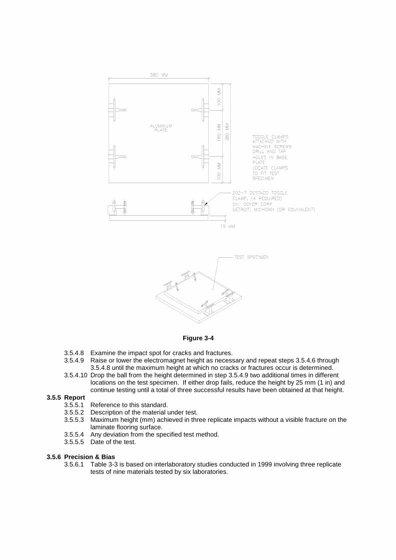
Figure 3-4
3.5.4.8 Examine the impact spot for cracks and fractures. 3.5.4.9 Raise or lower the electromagnet height as necessary and repeat steps 3.5.4.6 through
3.5.4.8 until the maximum height at which no cracks or fractures occur is determined. 3.5.4.10 Drop the ball from the height determined in step 3.5.4.9 two additional times in different
locations on the test specimen. If either drop fails, reduce the height by 25 mm (1 in) and continue testing until a total of three successful results have been obtained at that height.
3.5.5 Report 3.5.5.1 Reference to this standard. 3.5.5.2 Description of the material under test. 3.5.5.3 Maximum height (mm) achieved in three replicate impacts without a visible fracture on the
laminate flooring surface. 3.5.5.4 Any deviation from the specified test method. 3.5.5.5 Date of the test.
3.5.6 Precision & Bias
3.5.6.1 Table 3-3 is based on interlaboratory studies conducted in 1999 involving three replicate tests of nine materials tested by six laboratories.

Material Mean Sr SR Ir IR A 1172 58 260 164 732 B 1268 52 355 147 1001 C 1437 130 404 366 1138 D 1573 79 422 223 1191 E 1575 156 309 440 873 F 1784 74 451 209 1271 G 1977 136 377 382 1064 H 2020 75 348 211 982 I 2087 145 469 409 1324
Table 3-3
3.5.6.2 In Table 3-3, for the materials indicated:
3.5.6.2.1 Mean is the average of test results for all replicates from all labs. 3.5.6.2.2 Sr is the within-laboratory standard deviation of the mean and Ir = 2.83Sr (see
3.5.7.2.4 for application of Ir). 3.5.6.2.3 SR is the between-laboratory standard deviation of the mean and IR = 2.83SR (see
3.5.7.2.5 for application of IR). 3.5.6.2.4 Repeatability – In comparing two mean values for the same material obtained by
the same operator using the same equipment on the same day, the means should be judged not equivalent if they differ by more than the Ir value for that material and condition.
3.5.6.2.5 Reproducibility – In comparing two mean values for the same material obtained by different operators using different equipment on different days, the means should be judged not equivalent if they differ by more than the IR value for that material and condition. (This applies between different laboratories or between different equipment within the same laboratory.)
3.5.6.3 The judgments per 3.5.6.2.4 and 3.5.6.2.5 will have an approximate 95% (0.95) probability of being correct.
3.5.6.4 Other materials may give somewhat different results. 3.6 SMALL BALL IMPACT RESISTANCE 3.6.1 Scope
This test measures the ability of laminate flooring to resist fracture due to impact by a small diameter ball.
3.6.2 Test Apparatus
3.6.2.1 Impact apparatus as shown in Figure 3-5. 3.6.2.2 Impact dart weighing 25.0 g + 0.5 g (0.88 oz + 0.02 oz). It shall consist of a steel or brass
dart tipped with a 5 mm (0.197 in) diameter steel ball. The spherical surface of the ball shall have no damaged or flattened surface. See Figure 3-5.
3.6.2.3 Dry graphite lubricant. 3.6.2.4 Overhead lighting consisting of cool white fluorescent light with the bulbs positioned
parallel to the line of sight and providing an intensity of 800 lux to 1100 lux (75 foot-candles to 100 foot-candles) at the specimen surface when examined.
3.6.2.5 Black, water washable marking pen (suitable for overhead transparencies). 3.6.2.6 Manufacturer’s underlayment or underlayment foam as a closed-cell foam with a thickness
of 2.0 mm ± 0.5 mm (0.08 in + 0.02 in) and a density of 35 kg/m3 + 5 kg/m3 (2.2 lb/ft3 + 0.3 lb/ft3).
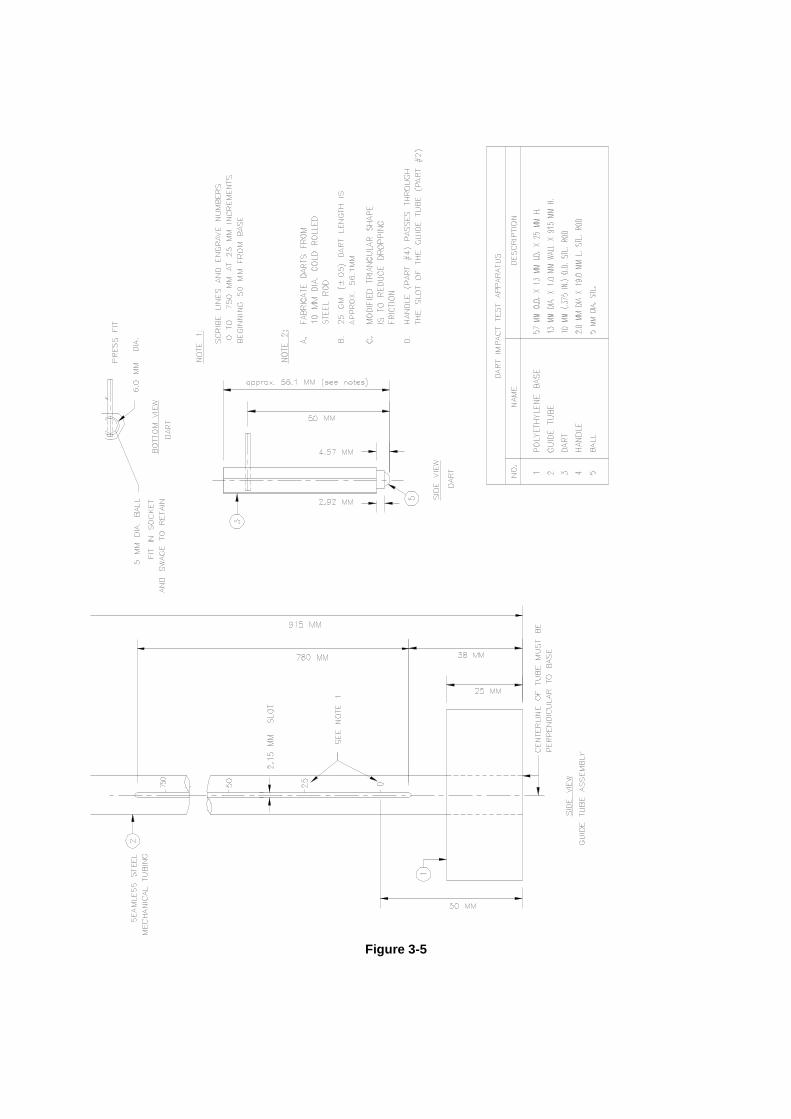
Figure 3-5
3.6.2.7 Environmental Chamber maintained at 23oC + 3oC (73oF + 5oF) and relative humidity of 50% + 5%.
3.6.2.8 Clean, soft cloth.
3.6.3 Specimens 3.6.3.1 Specimens shall be 200 mm x 200 mm x thickness (8 in x 8 in x thickness). In cases
where material is less than 200 mm (8 in) in one dimension of the face, the specimen shall measure 200 mm x nominal width x nominal thickness (8 in x nominal width x nominal thickness).
3.6.4 Procedure
3.6.4.1 Condition the samples for at least 48 hours prior to the test at a temperature of 23oC + 3oC (73oF + 5oF) and a relative humidity of 50% ± 5%.
3.6.4.2 Lubricate the inside diameter of the tube assembly with the dry graphite lubricant to minimize friction with the dart.
3.6.4.3 Place the specimen face up, on underlayment foam of similar size as the specimen. 3.6.4.4 Place the specimen/underlayment assembly face up on a rigid horizontal surface. 3.6.4.5 Place the impact apparatus on the decorative surface of the specimen so that the edge of
the round base is tangent to two edges of the specimen at one corner. The bottom of the circular base shall be flush against the face of the specimen.
3.6.4.6 Position the dart at a height of 125 mm (5 in). 3.6.4.7 Release the dart and impact the face of the specimen. Catch the dart when it rebounds so
that multiple impacts do not occur. 3.6.4.8 Move the dart to the right 15 mm (5/8 in) while keeping the edge of the circular base
tangent to one edge of the specimen. See Figure 3-6. 3.6.4.9 Position the dart at a height of 150 mm (6 in). 3.6.4.10 Release the dart and impact the face of the specimen. Catch the dart when it rebounds so
that multiple impacts do not occur. 3.6.4.11 Repeat steps 3.6.4.9 and 3.6.4.10 while increasing the dart release height by 25 mm (1in)
with each impact along the first edge of the specimen. 3.6.4.12 Use the marking pen to ink the impact points. 3.6.4.13 Wipe the impact points with a clean, soft cloth to remove excess ink. 3.6.4.14 Failures are cracks and fractures that appear as hairline cracks, concentric circles, or
chips. Dents without breaking the surface do not indicate failure. 3.6.4.15 Beginning with the impact point of lowest height, follow the impact point path of increasing
impacts heights until 3 consecutive failures occur. If three consecutive failures are not observed, continue with steps 3.6.4.11 through 3.6.4.14 along edge two of the specimen.
3.6.4.16 Edge three and edge four may be used as needed until failure is noted or the highest impact release point is achieved without failure.
3.6.4.17 The impact resistance is the height value immediately preceding the series of three consecutive failures.
3.6.5 Report
3.6.5.1 Reference to this standard. 3.6.5.2 Description of the material under test. 3.6.5.3 Impact resistance as determined in 3.6.4.17. 3.6.5.4 Any deviation from the specified test method. 3.6.5.5 Date of the test.
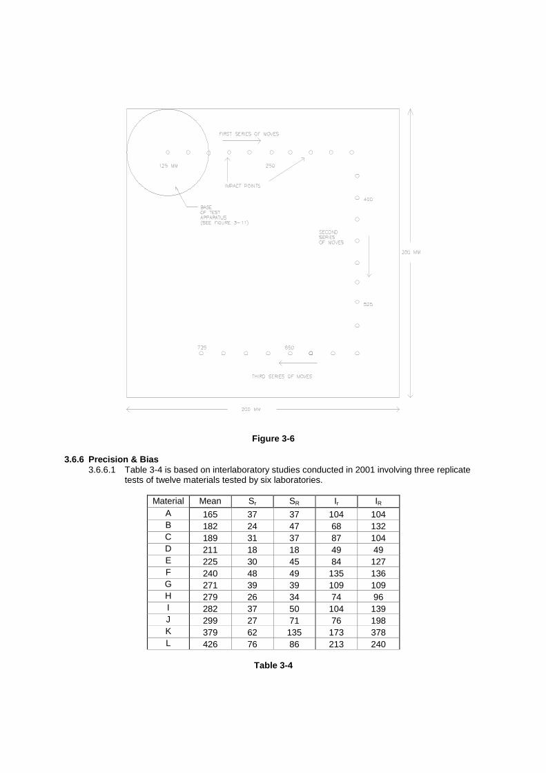
Figure 3-6 3.6.6 Precision & Bias
3.6.6.1 Table 3-4 is based on interlaboratory studies conducted in 2001 involving three replicate tests of twelve materials tested by six laboratories.
Material Mean Sr SR Ir IR
A 165 37 37 104 104 B 182 24 47 68 132 C 189 31 37 87 104 D 211 18 18 49 49 E 225 30 45 84 127 F 240 48 49 135 136 G 271 39 39 109 109 H 279 26 34 74 96 I 282 37 50 104 139 J 299 27 71 76 198 K 379 62 135 173 378 L 426 76 86 213 240
Table 3-4

3.6.6.2 In Table 3-4, for the materials indicated: 3.6.6.2.1 Mean is the average of test results for all replicates from all labs. 3.6.6.2.2 Sr is the within-laboratory standard deviation of the mean and Ir = 2.83Sr (see
3.6.6.2.4 for application of Ir). 3.6.6.2.3 SR is the between-laboratory standard deviation of the mean and IR = 2.83SR (see
3.6.6.2.5 for application of IR). 3.6.6.2.4 Repeatability – In comparing two mean values for the same material obtained by
the same operator using the same equipment on the same day, the means should be judged not equivalent if they differ by more than the Ir value for that material and condition.
3.6.6.2.5 Reproducibility – In comparing two mean values for the same material obtained by different operators using different equipment on different days, the means should be judged not equivalent if they differ by more than the IR value for that material and condition. (This applies between different laboratories or between different equipment within the same laboratory.)
3.6.6.3 The judgments per 3.6.6.2.4 and 3.6.6.2.5 will have an approximate 95% (0.95) probability of being correct.
3.6.6.4 Other materials may give somewhat different results. 3.7 WEAR RESISTANCE 3.7.1 Scope
This test measures the ability of the surface of laminate flooring to resist abrasive wear through the décor layer.
3.7.2 Test Apparatus
3.7.2.1 Abrasion apparatus. Taber model 5130 or equivalent. Abraser must be calibrated. See Appendix E
3.7.2.2 Abrasion wheels. Taber model S-32 or equivalent. 3.7.2.3 Zinc plate. Taber model S-34 or equivalent. 3.7.2.4 Sandpaper shall be 180 grit aluminum oxide in an open coat with a glue bond on “A”
weight finishing paper. It shall measure 12.7 mm x 158.7 mm (0.50 in x 6.25 in). Taber model S-42 or equivalent.
3.7.2.5 Double-faced adhesive tape 12.7 mm (0.50 in) wide. 3.7.2.6 Analytical balance with resolution and accuracy to 0.001g. 3.7.2.7 Environmental Chamber maintained at 23oC + 3oC (73oF + 5oF) and relative humidity of
50% + 5%. 3.7.2.8 Isopropyl alcohol. 3.7.2.9 Powdered talc. 3.7.2.10 Clean, soft cloth. 3.7.2.11 TAPPI Size Estimation Chart. 3.7.2.12 Swedish Standards Institution Article No. 21824
3.7.3 Specimens
3.7.3.1 For each test two specimens shall be randomly selected from the manufactured lot. No two specimens shall be selected from the same tile. Each specimen shall measure approximately 100 mm x 100 mm x nominal thickness (4 in x 4 in x nominal thickness) and have a 6.5 mm (1/4 in) hole drilled in the center.
3.7.4 Calibration
3.7.4.1 The sandpaper strips shall be conditioned and stored at 23oC± 3oC (73oF± 5oF) and a relative humidity of 50% ± 5%. They shall be maintained in this environment for at least 48 hours prior to use.
3.7.4.2 Attach the S-32 wheels, and a load of 500 gram weight on each wheel.

3.7.4.3 The vacuum shall be set to 90% capacity. The vacuum pickup nozzle shall be approximately 6 mm (1/4 in) from the surface that is being abraded.
3.7.4.4 Dust the S-32 wheels with powdered talc. 3.7.4.5 Apply a sandpaper strip to the periphery of each of the two S-32 wheels. Join the ends to
avoid overlap of the ends and/or contamination of the grit. 3.7.4.6 Attach a zinc plate to the apparatus and lower the two wheels to the surface of the plate. 3.7.4.7 Set the abrader for 500 cycles and commence the test. The vacuum will start and stop
automatically. 3.7.4.8 At the end of 500 cycles, raise the wheels and remove the zinc plate. 3.7.4.9 Clean the plate with isopropyl alcohol and a clean soft cloth. Allow the plate to dry. 3.7.4.10 Weigh the plate to the nearest 0.001 g and record as W1. 3.7.4.11 Return the plate to the abrader. 3.7.4.12 Remove the old sandpaper and apply fresh sandpaper. 3.7.4.13 Lower the abrader wheels and set the abrader to run an additional 500 cycles. 3.7.4.14 Repeat steps 3.7.4.7 through 3.7.4.10. Record the second weight as W2. 3.7.4.15 Repeat 3.7.4.14 to obtain W3. 3.7.4.16 (W1 – W2) and (W2 – W3) must be 110 mg + 30 mg. If either difference is out of the range,
disregard those values and repeat the calibration as outlined above. If the second set of weight differences is also out of range, reject the lot of sandpaper and replace with another lot.
3.7.4.17 Calculate a correction factor for a lot of sandpaper as follows:
Correction Factor = (W1 – W2) + (W2 – W3) 2 x 110
3.7.5 Procedure
3.7.5.1 Clean the surface of the specimen with isopropyl alcohol and a clean soft cloth. Allow the specimen to dry.
3.7.5.2 Attach the specimen to the abrader. 3.7.5.3 Dust the abrader wheels with powdered talc and apply fresh sandpaper to the wheels.
Reset the counter to 0. 3.7.5.4 Start the abrader and inspect the specimen every 200 cycles. Replace the sandpaper
every 200 cycles. 3.7.5.5 Continue until the initial wear point begins to show for the specimen. Continue the test and
inspect every 50 cycles. Compare the wear areas with a TAPPI Size Estimation Chart. Initial wear point is defined as a visible spot greater than or equal to 0.60 mm2 (0.0009 in2) where the décor design has been removed from the surface wear layer and the base paper is exposed. At the point of initial wear in one quadrant, inspect the sample every 25 cycles until the initial wear point in three quadrants is achieved. Refer to the Swedish Standards Institution Article No. 21824 for a more complete visual explanation of the initial wear point. Once an initial wear point in three quadrants has been reached the test is terminated and the total cycles for the specimen are recorded as the specimen’s initial wear point.
3.7.6 Calculations
3.7.6.1 Multiply the number of cycles required to reach an initial point for each sample by the correction factor.
3.7.6.2 Average the two corrected results. 3.7.6.3 Round the average to the nearest 50 cycles. 3.7.6.4 Wear Resistance is the average of the two corrected initial points rounded to the nearest
50 cycles. 3.7.7 Report
3.7.7.1 Reference to this standard. 3.7.7.2 Description of the material under test. 3.7.7.3 Wear resistance.
3.7.7.4 Any deviation from the specified test method. 3.7.7.5 Date of the test.
3.7.8 Precision & Bias
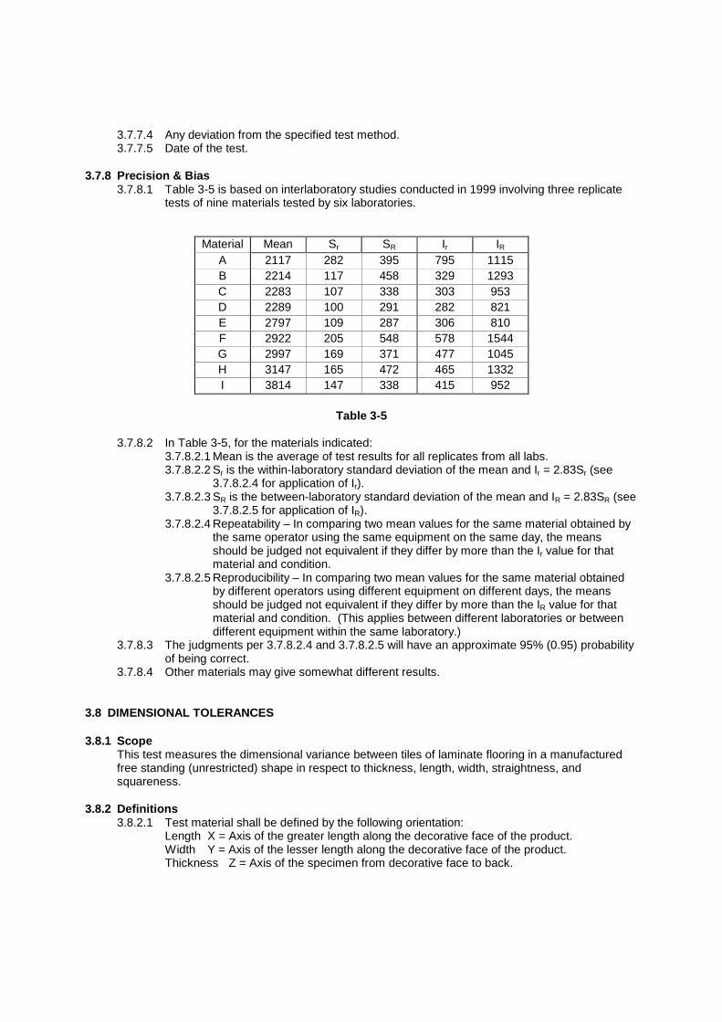
3.7.8.1 Table 3-5 is based on interlaboratory studies conducted in 1999 involving three replicate tests of nine materials tested by six laboratories.
Material Mean Sr SR Ir IR A 2117 282 395 795 1115 B 2214 117 458 329 1293 C 2283 107 338 303 953 D 2289 100 291 282 821 E 2797 109 287 306 810 F 2922 205 548 578 1544 G 2997 169 371 477 1045 H 3147 165 472 465 1332 I 3814 147 338 415 952
Table 3-5
3.7.8.2 In Table 3-5, for the materials indicated:
3.7.8.2.1 Mean is the average of test results for all replicates from all labs. 3.7.8.2.2 Sr is the within-laboratory standard deviation of the mean and Ir = 2.83Sr (see
3.7.8.2.4 for application of Ir). 3.7.8.2.3 SR is the between-laboratory standard deviation of the mean and IR = 2.83SR (see
3.7.8.2.5 for application of IR). 3.7.8.2.4 Repeatability – In comparing two mean values for the same material obtained by
the same operator using the same equipment on the same day, the means should be judged not equivalent if they differ by more than the Ir value for that material and condition.
3.7.8.2.5 Reproducibility – In comparing two mean values for the same material obtained by different operators using different equipment on different days, the means should be judged not equivalent if they differ by more than the IR value for that material and condition. (This applies between different laboratories or between different equipment within the same laboratory.)
3.7.8.3 The judgments per 3.7.8.2.4 and 3.7.8.2.5 will have an approximate 95% (0.95) probability of being correct.
3.7.8.4 Other materials may give somewhat different results. 3.8 DIMENSIONAL TOLERANCES 3.8.1 Scope
This test measures the dimensional variance between tiles of laminate flooring in a manufactured free standing (unrestricted) shape in respect to thickness, length, width, straightness, and squareness.
3.8.2 Definitions
3.8.2.1 Test material shall be defined by the following orientation: Length X = Axis of the greater length along the decorative face of the product. Width Y = Axis of the lesser length along the decorative face of the product. Thickness Z = Axis of the specimen from decorative face to back.

(Note: For products with the decorative face in a square format (all edges of equal nominal length), the X and Y axes are arbitrarily chosen from the orthogonal axis parallel to the edges of the product.)
3.8.2.2 Straightness: The freedom of an edge from curves, bends, angles, or irregularities. 3.8.2.3 Squareness: Conformance of a corner and the two adjacent edges in question to a right
(90o) angle. 3.8.3 Test Apparatus
3.8.3.1 Straight edge of length greater than the long axis (X-axis dimension) of the specimen and having maximum straightness deviation of 0.05 mm/m (0.0006 in/ft).
3.8.3.2 A flat horizontal surface of dimensions greater than the specimen. 3.8.3.3 A caliper of jaw capacity suitable for measuring the length (X-axis dimension) and width (Y-
axis dimension) giving an accuracy of 0.05 mm (0.002 in). 3.8.3.4 A micrometer suitable for measuring thickness (Z-axis dimension) having flat and parallel
circular measuring surfaces of 6.34 mm (0.25 in) diameter and an accuracy of 0.01 mm (0.0004 in).
3.9.3.5 Feeler gauge with thickness leaves in increments of 0.05 mm (0.002 in) and total range of 0.05 mm to 1.0 mm (0.002 in to 0.040 in).
3.8.3.6 The instruments utilized in this method shall have current NIST traceable certificates available to assure current calibration of the equipment. Note: Feeler gauges cannot be certified.
3.8.4 Specimens
3.8.4.1 Test specimens shall be of the nominal size as produced by the manufacturer. The specimens shall not be restricted from movement during the tests (i.e. bonded to other materials).
3.8.4.2 Five (5) specimens shall constitute a set for purposes of dimensional testing.
3.8.5 Procedure 3.8.5.1 Condition the samples for at least 48 hours prior to the test at a temperature of 23oC ± 3oC
(73oF + 5oF) and a relative humidity of 50% ± 5%. 3.8.5.2 The specimen under test must be a single sample of nominal manufactured size. 3.8.5.3 The surfaces of the specimen must be free from foreign bodies and any protrusions from
the face and edges of the specimen. These materials must be removed prior to the start of the test.
3.8.5.4 Proceed to the subsequent section of the method titled in the dimensional area for which tests are to be conducted. In the case of multiple parameters to be checked, the order of the tests is modeled after the order of this specification.
3.8.5.5 Length (X axis dimension) 3.8.5.5.1 Using a suitable caliper, close the jaws gently onto the edge of the decorative
surface between which the length is to be determined. Do not force the instrument. (See Figure 3-7 for location of measurements).
3.8.5.5.2 Record the length indicated by the caliper to the nearest 0.05 mm (0.002 in). 3.8.5.5.3 Two length measurements (L), 20 mm (0.80 in) from each long edge parallel to
the X-axis, are to be made on each of the five specimens for a total of ten length measurements.
3.8.5.5.4 Determine the maximum (Lmax) and minimum (Lmin) of the ten length values. Calculate the range of lengths (Lrange) as Lrange = Lmax - Lmin.
3.8.5.5.5 Report Lrange.
Figure 3-7
3.8.5.6 Width (Y axis dimension)
3.8.5.6.1 Using a suitable caliper, close the jaws gently onto the edge of the decorative surface between which the width is to be determined. Do not force the instrument. See Figure 3-8 for location of measurements.
3.8.5.6.2 Record the width indicated by the caliper to the nearest 0.05 mm (0.002 in). 3.8.5.6.3 Two width measurements (W), 150 mm (6 in) from each short edge parallel to the
Y-axis, are to be made on each of the five specimens for a total of ten width measurements. (Note: On square tiles, the width measurements are made 20 mm (0.80 in) from the two edges not used for length measurements).
3.8.5.6.4 Determine the maximum (Wmax) and minimum (Wmin) of the ten width values. Calculate the range of widths (Wrange) as Wrange = Wmax – Wmin.
3.8.5.6.5 Report Wrange.
Figure 3-8
3.8.5.7 Thickness (Z axis dimension)
3.8.5.7.1 Using a suitable micrometer, close the jaws gently onto the surfaces between which the thickness is to be determined. Do not force the instrument. See Figure 3-9 for location of measurements.
3.8.5.7.2 Record the thickness indicated by the micrometer to the nearest 0.025 mm (0.001 in).
3.8.5.7.3 Four thickness measurements (T), 100 mm (4 in) from each short edge and 25 mm (1 in) from each long edge, are to be made on each of the five specimens for a total of 20 thickness measurements. See Figure 3-9.
3.8.5.7.4 Determine the maximum (Tmax) and minimum (Tmin) of the 20 thickness values. Calculate the range of thickness (Trange) as Trange = Tmax – Tmin.
3.8.5.7.5 Report Trange.

Figure 3-9
3.8.5.8 Straightness 3.8.5.8.1 Place the specimen, decorative layer up, on a flat horizontal surface. 3.8.5.8.2 Place the straight edge against the edge of the specimen parallel to the X-axis so
that the straight edge is touching the specimen at the decorative edge. 3.8.5.8.3 If a gap is visible, insert vertically a feeler gauge of successive thickness leaves
into the gap at the maximum deviation until the largest thickness leaf (L) that will fit without force into the gap is found.
Note1: If the surface layer demonstrates a concave appearance, measure the gap at the point of maximum deviation and record the measured gap. See Figure 3-10. In this instance S = L.6
Note2: If the surface layer demonstrates a convex appearance, place the decorative edge against the straight edge as illustrated in Figure 3-11. Measure the gap at the point of maximum deviation, calculate and record the value of measured gap/2 expressed as S = L/2.
3.8.5.8.4 Repeat 3.8.5.8.2 to 3.8.5.8.3 for the opposite and adjacent edges for a total of four values per test specimen.
3.8.5.8.5 Repeat 3.8.5.8.1 to 3.8.5.8.4 for all 5 samples for a total of 20 values. 3.8.5.8.6 Calculate the maximum deviation from straightness (Smax) as the maximum of the
20 values determined in 3.8.5.8.5. 3.8.5.8.7 Report Smax to the nearest 0.05 mm (0.002 in).
Concave Edge
Figure 3-10
Convex Edge
Figure 3-11
straight edge
L
Insert feeler gauge vertically at point of maximum deviation. Recorded value S = L.
straight edge
Insert feeler gauge at point of maximum deviation. Recorded value S = L / 2
L

3.8.5.9 Squareness Note: Specimen must conform to length, width, and straightness tolerances prior
to proceeding. 3.8.5.9.1 Place the specimen, decorative layer up, on the flat horizontal surface. 3.8.5.9.2 Measure the decorative surface of the tile from one corner to the opposing corner
and again for the remaining corners to obtain two diagonal measurements (Q1 and Q2) as shown in Figure 3-12.
3.8.5.9.3 Obtain the maximum absolute value (Qdif) of the difference of the two diagonal measurements as demonstrated by Qdif = | Q1 – Q2 | for each of the tested specimens.
3.8.5.9.4 Report Qmax as the maximum Qdif value to the nearest 0.05 mm (0.002 in).
Figure 3-12 3.8.6 Report
3.8.6.1 Reference to this standard. 3.8.6.2 Description of the material under test. 3.8.6.3 Dimensional characteristics as determined by the appropriate section. 3.8.6.4 Any deviation from the specified test method. 3.8.6.5 Date of the test.
3.8.7 Precision & Bias 3.8.7.1 Test method precision and bias have not been established at this time. It is currently
under consideration of the NALFA Technical Committee. 3.9 CASTOR CHAIR RESISTANCE 3.9.1 Scope
The test specifies a method for determining the change of appearance and stability of a laminate floor, including joints, under the movement of a castor chair.
3.9.2 Test Apparatus
3.9.2.1 Castor chair apparatus – Feingerate Baumberg Model Rollstuhltestgerat Type 28167 or equivalent with weights installed to provide 90kg (198 lbs) load.
3.9.2.2 The 3 castors shall be either 1) Single-wheel polyamide with a Shore A hardness of 95 + 5 or, 2) Type W polyurethane. The castor wheel shall be 50 mm (2 in) diameter and 20 mm (3/4 in) wide.
3.9.2.3 Manufacturer’s underlayment or underlayment foam as a closed-cell foam with a thickness of 2.0 mm + 0.5mm (0.08 in + 0.02 in) and a density of 35 kg/m³ + 5 kg/m³ (2.2lb/ft³ + 0.3lb/ft³) or manufacturer’s recommended underlayment.
3.9.2.4 Overhead lighting consisting of cool white fluorescent light with the bulbs positioned parallel to the line of sight and providing an intensity of 800 lux to 1100 lux (75 foot-candles to 100 foot-candles) at the specimen surface when examined.
Q1
Q2

3.9.2.5 Denatured alcohol. 3.9.2.6 Clean, soft cloth.
3.9.3 Specimens
3.9.3.1 Specimens shall be circular with a diameter of 750 mm (29.5 in) x the nominal thickness of the material and shall include at least one longitudinal and one horizontal joint located in the test area of the castors. Joints in the specimen shall be treated according to the manufacturer’s instructions.
3.9.2.4 3.9.3.2 Specimen shall be tested over manufacturer’s recommended underlayment, or underlayment foam as a closed-cell foam with a thickness of 2.0 mm + 0.5mm (0.08 in + 0.02 in) and a density of 35 kg/m³ + 5 kg/m³ (2.2lb/ft³ + 0.3lb/ft³).
3.9.4 Procedure
3.9.4.1 Condition the samples for at least 48 hours prior to the test at a temperature of 23oC + 3oC (73oF + 5oF) and a relative humidity of 50% ± 5%.
3.9.4.2 Clean the castors with a soft cloth and alcohol. Inspect and replace if necessary. 3.9.4.3 Mount the specimen on the platform over the underlayment. Tape or bind edges of
samples to make sure board slide does not occur during test. 3.9.4.4 Lower the castor base to the surface of the specimen and load weights. Adjust the
vacuum head to remove debris. 3.9.4.5 Preset the counter for 25,000 or 35,000 revolutions, as required and turn on the apparatus. 3.9.4.6 At the end of the test remove the castor base and examine the specimen with standard
lighting and viewing distances/angles. Record any damage such as delamination, opening of seams, or crazing. Changes in gloss or sheen are not considered damage and should be ignored.
3.9.5 Report
3.9.5.1 Reference to this standard. 3.9.5.2 Description of the material under test. 3.9.5.3 List the nature of observable damage and the number of revolutions conducted on the
specimen. 3.9.5.4 Any deviation from the specified test method. 3.9.5.5 Date of the test.
3.9.6 Precision & Bias
3.9.6.1 Test method precision and bias have not been established at this time. It is currently under consideration of the NALFA Technical Committee.
3.10 SURFACE BOND 3.10.1 Scope
This test measures the force required to delaminate or split away the surface of laminate flooring plank or tile.
3.10.2 Test Apparatus 3.10.2.1 A device to produce a groove in the laminate plank or tile. 3.10.2.2 A barbell or mushroom shaped test pad having a base diameter of 35.6+/- 0.1mm(1.4 in
+/- 0.005 in). See Figure 4 – 1 for example. Pad must be sufficiently strong as to not distort under test load parameters.
3.10.2.3 Test Frame with 38.0 +/- 0.1mm(1.5 in +/- 0.005 in) hole. See Figure 4 – 3 Test frame must be sufficiently strong as to not distort under test load parameters.
3.10.2.4 Tensile Testing Apparatus, capable of holding the Surface Bond Test Frame and having adequate movement and load capability to pull samples apart.
3.10.2.5 Grip fixture sized to fit test pad (See Figure 4 – 1 and Figure 4 – 4), and fitted with gimbal or universal joint.

Figure 4 – 1 Figure 4-1 shows metric values. To convert mm values to inches multiply the value shown by 0.03937.

Figure 4 - 2
Figure 4 – 3

Figure 4 - 4 3.10.3 Specimens
3.10.3.1 For each test, take four specimens from the product to be tested. No two specimens shall be selected from the same plank or tile.
3.10.4 Procedure
3.10.4.1 Cut specimen to size: 50mm x 50 mm X nominal thickness (2 in X 2 in X Nominal Thickness).
3.10.4.2 Using the grooving device prepare specimen in accordance to Figure 4 – 2. Circular groove cut into specimen face shall be through the decorative face and 0.0 – 0.3mm (0.012 in) into the core and should give a raised circular test area having a 35.7+/- 2 mm (1.4 in +/- 0.1 in) diameter. This will give nominal 1000 sq mm (1.55 sq-in) test area.
3.10.4.3 Using a hot melt adhesive, with melting point below 150 Deg C, (300 Deg F) spread a thin layer of adhesive across the face of the heated steel pad.
3.10.4.4 Carefully place the pad with hot adhesive onto the face of the specimen making sure pad is centered on the test area.
3.10.4.5 Lightly weight or hold pad in place until adhesive has cooled (Apply nominal 0.1 – 0.2 N/sq-mm force loading)(15 psi).
3.10.4.6 After the adhesive has cooled and hardened place mounted sample into test frame. See Figure 4 – 4.
3.10.4.7 Using Tensile Tester, apply a constant speed so that failure or delamination occurs within 30 – 90 seconds.

3.10.4.8 Record force at failure and where the location of failure occurred i.e. within the coating, within the glue line, between the coating and the core, within the core, etc. If partial split, describe rough percentage attributable to each failure mode.
3.10.4.9 If glue line failure occurs, reject the value unless above the prescribed specification criteria.
3.10.4.10 If an individual surface bond value varies more than 0.4N/ sq-mm (60 psi) from the average repeat the test using another set of specimens.
3.10.5 Calculations
3.10.5.1 Individual Surface Bond Value (SBn) = Maximum Force (Newtons)/Area (mm) in order to
cause a delamination or splitting away of the top surface of the laminate product. 3.10.5.2 The reported Surface Bond value is the average. It is determined by taking the four
individual Surface Bond values and calculating the average. 3.10.5.3 Average Surface Bond Value = (SB1 + SB2 + SB3 + SB4)/4.
3.10.6 Report
3.10.6.1 Reference to this standard. 3.10.6.2 Description of the material under test. 3.10.6.3 Surface bond measurement. 3.10.6.4 Report failure location. 3.10.6.5 Any deviation from the specified test method. 3.10.6.6 Date of the test. 3.10.6.7 Who performed the testing.
3.10.7 Precision & Bias
3.10.7.1 Test method precision and bias have not been established at this time. Repeatability measurements gave a repeatability sigma of 0.6 N/sq mm (88.6 psi) for a 99.73 % confidence level. Additional work is under consideration by the NALFA Technical Committee.

Section 4 THIRD PARTY CERTIFICATION
4.1 COMPLIANCE
When reference is made to this standard in statements of compliance, the laminate product shall meet all of the requirements in their entirety. Any laminate marked or labeled as being compliant with this standard shall meet all of the requirements of this standard and shall be certified.
4.2 CERTIFICATION
All Certification and testing shall be performed by an independent testing lab. Compliant flooring shall be labeled with the NALFA/ANSI mark and shall be listed. A party seeking certification shall submit its results, as well as identifying information for the test lab, to NALFA for review and verification. Laminate flooring must undergo third party testing at least every five years or whenever a product is substantially changed.
4.3 EFFECTIVE DATE
The certification requirements shall become effective six months after the publication date of this standard.
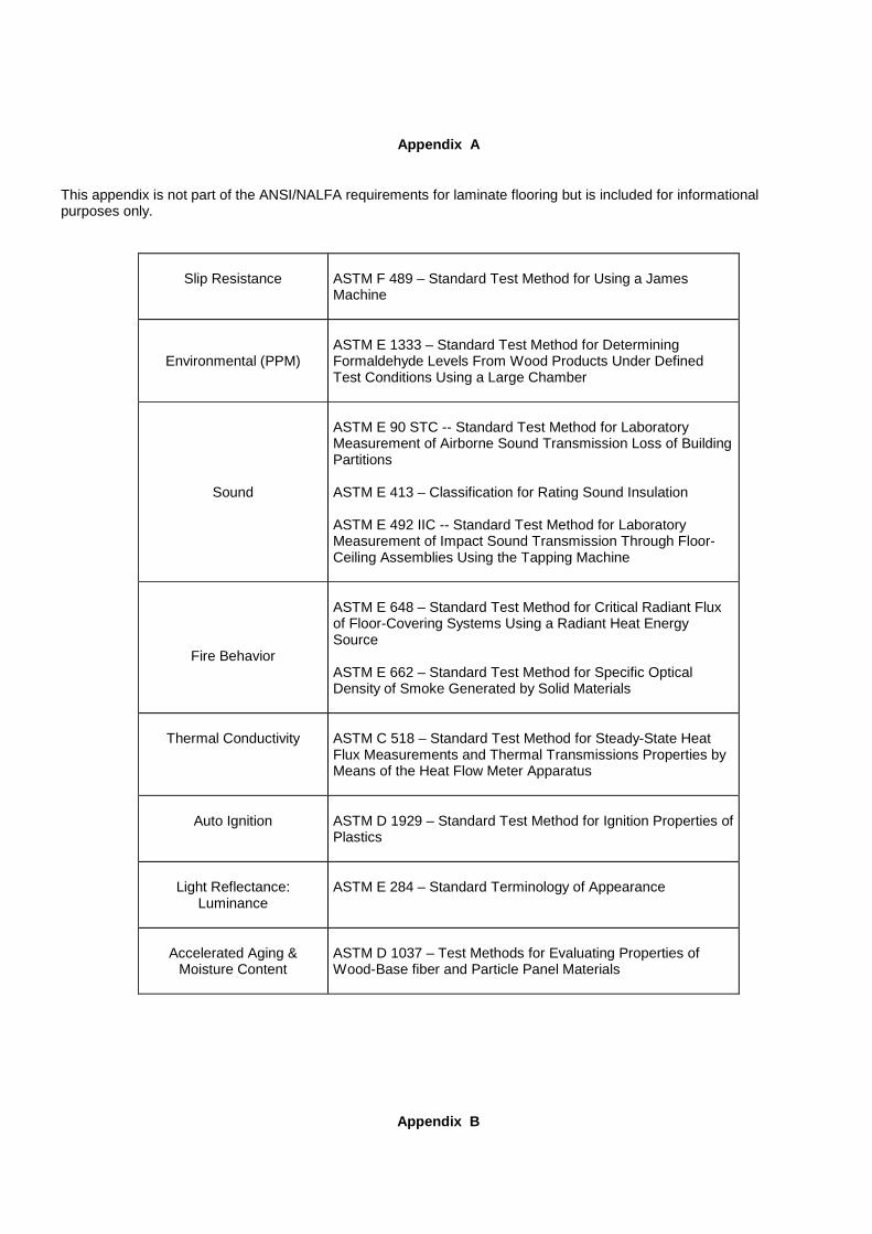
Appendix A This appendix is not part of the ANSI/NALFA requirements for laminate flooring but is included for informational purposes only.
Slip Resistance
ASTM F 489 – Standard Test Method for Using a James Machine
Environmental (PPM)
ASTM E 1333 – Standard Test Method for Determining Formaldehyde Levels From Wood Products Under Defined Test Conditions Using a Large Chamber
Sound
ASTM E 90 STC -- Standard Test Method for Laboratory Measurement of Airborne Sound Transmission Loss of Building Partitions ASTM E 413 – Classification for Rating Sound Insulation ASTM E 492 IIC -- Standard Test Method for Laboratory Measurement of Impact Sound Transmission Through Floor-Ceiling Assemblies Using the Tapping Machine
Fire Behavior
ASTM E 648 – Standard Test Method for Critical Radiant Flux of Floor-Covering Systems Using a Radiant Heat Energy Source ASTM E 662 – Standard Test Method for Specific Optical Density of Smoke Generated by Solid Materials
Thermal Conductivity
ASTM C 518 – Standard Test Method for Steady-State Heat Flux Measurements and Thermal Transmissions Properties by Means of the Heat Flow Meter Apparatus
Auto Ignition
ASTM D 1929 – Standard Test Method for Ignition Properties of Plastics
Light Reflectance:
Luminance
ASTM E 284 – Standard Terminology of Appearance
Accelerated Aging &
Moisture Content
ASTM D 1037 – Test Methods for Evaluating Properties of Wood-Base fiber and Particle Panel Materials
Appendix B
This appendix is not part of the ANSI/NALFA requirements for laminate flooring, but is included for informational purposes only. Moisture Content 1.0 Scope
The test measures the moisture content of laminate flooring. 1.1 Method Addendum 1.1.1 The test method shall conform to ASTM D 1037 in Sections 119 through 120 with additional criteria: 1.1.2 Sample size shall consist of two specimens with a size of 75 mm x 75 mm (3 in x 3 in) with smoothly and squarely
trimmed edges collected from opposite ends of a sample. 1.1.3 Specimens shall not be preconditioned. 1.1.4 Weigh specimen and place in oven 103oC ± 2°C (217oF + 4oF) for 48 hours. 1.1.5 Reweigh specimen directly after removal from oven. 1.1.6 Calculate moisture content per Section 120.1. 1.2 Test Report 1.2.1 Average moisture content of the two specimens. Light Reflectance (Luminance) 2.0 Scope
This test measures light reflectance based on the definition of Luminance Factor of laminate flooring. 2.1 Method Addendum 2.1.1 The definition shall conform to ASTM E 284 using the following methodology. 2.1.2 Luminance Factor is defined as the tristimulus value Y. 2.1.3 Values are to be determined by Hunter Lab ColorQuest II Spectrophotometer or equivalent using C.I.E. system
guidelines with cool white fluorescent illuminate, 10-degree observer, spectral reflection included. 2.2 Test Report 2.2.1 Calculated Tristimulus value Y shall be reported.
Appendix C
Glossary This appendix is not part of the ANSI/NALFA requirements for laminate flooring but is included for informational purposes only. 1. Acclimation: Adaptation of the laminate floor to its installation environment. 2. Acoustical Properties: Absorbance, reflection or transmission of sound waves. 3. Adhesion: A chemical process by which two materials can be joined together. 4. Antistatic: Ability to limit the accumulation of static electricity on a surface. 5. Backer: A material bonded to the back of the substrate. 6. Balanced Construction: A panel construction that has materials of similar properties bonded to both sides of the
panel. 7. Bond: Adhesion. 8. Chemical Resistance: The degree to which a material resists visual or physical degradation from exposure to
various household and/or industrial chemicals. 9. Colorfastness: The ability of a material to retain its original color upon exposure to light or other source of
degradation (i.e., light resistance). 10. Compact Laminate: High Pressure Laminate greater than or equal to 2 mm (0.08 in) in thickness. 11. Continuous Press Laminate (CPL): A manufacturing process where the laminate is formed on a continuous double-
belted press. 12. Continuous Laminate Flooring: A product created by permanently bonding a continuous press laminate to a core. 13. Core: The center of a panel (e.g., surface layer, core, and backer). 14. Crook: A specific type of warp when a panel has a curvature from end to end, edgewise, from a straight line (i.e.,
banana). 15. Crowning: A specific type of warp when a panel assumes the shape of an inverted “U” along the length or width
dimensions of the face (i.e., convex). 16. Cupping: A specific type of warp where a panel assumes the shapes of a “U” along the length or width dimensions
of the face (i.e. concave). 17. Décor Layer: The layer of laminate flooring providing visual aesthetic properties. 18. Deflection: The bending of a material between supports when a load is applied. 19. Delaminating: Separation of the panel’s layer(s). 20. Density: Unit weight per volume of a panel expressed in lb/ft3 or kg/m3. 21. Depression: A dent in the surface of a panel. 22. Dimensional Stability: The ability of a material to resist changes in measured dimensions caused by environmental
factors (e.g., moisture or temperature). 23. Direct Laminate Flooring: A product where resin impregnated material layer(s) is permanently bonded to the core. 24. Direct Press Laminate (DPL): A laminating process by where the wear layer and décor surface are bonded directly
to the substrate in a single step. 25. Embossing: A process by which the surface of the panel is given a texture. 26. Equilibrium Moisture Content: The moisture content at which the material neither gains nor loses moisture at a
given relative humidity. 27. Expansion Gap: A space necessary between fixed objects (i.e. walls of a room, pipes, and cabinets) and between
the material itself to allow for the movement of the material. 28. Fiberboard: A core material primarily composed of cellulose fibers combined with synthetic resins or other suitable
bonding systems under heat and pressure. The materials are usually designated as low, medium, or high density (e.g., MDF or HDF).
29. Flame Spread: Measurement of the flame propagation along the surface of a material. 30. Floating Floor: Installation method by which the flooring panels are connected together and not attached to the
subfloor. 31. High Density Fiberboard (HDF): A fiberboard with density greater than 800 kg/m3 (50 lb/ft3). 32. High Pressure Laminate (HPL): A laminating process where materials are consolidated under heat and pressure
exceeding 5.17 MPa (750 psi). 33. High-Pressure Laminate Flooring: A product created by permanently bonding high-pressure decorative laminate to
a core. 34. Impact Resistance: Ability to resist fracture or damage from a falling object. 35. Inlay: A decorative effect used in flooring by combining elements of the same material but with different colors or
patterns (e.g., borders or feature strips). 36. Laminate: A product made by bonding together two or more layers of material. 37. Laminate Flooring: A rigid floor covering with a surface layer consisting of one or more thin sheets of a fibrous
material (usually paper), impregnated with aminoplastic thermosetting resins (usually melamine). These sheets are
either pressed as such (HPL, CPL, Compact), and in the case of HPL or CPL bonded on a substrate, or in the case of DPL directly pressed on a substrate. The product is normally finished with a backing primarily used as a balancing material. Its performance values are set by the NALFA/ANSI Standard.
38. Medium Density Fiberboard (MDF): A type of core material primarily composed of lignocellulosic fibers combined with a synthetic resin or other suitable bonding system and bonded together under heat and pressure.
39. Melamine Resin: A thermosetting resin used in the impregnation process of materials used to make laminate flooring.
40. Moisture Content: The amount of water in the material, usually expressed as a percentage of the dry weight. 41. Moisture Meter: A tool used to measure moisture content. 42. Overlay: A product of paper, plastic, film, metal foil, or other material incorporated into the laminate flooring surface
that provides the wear resistance and protection. 43. Panels: Finished sections of the laminate flooring (e.g. planks, tiles, and squares). 44. Particleboard: A core material primarily composed of cellulosic materials (usually wood), generally in the form of
discrete pieces or particles, as distinguished from fibers. The cellulosic material is combined with a synthetic resin or other suitable bonding system by a process in which the interparticle bond is created by the bonding system under heat and pressure.
45. Pattern End Matched: When the ends of the flooring panels, typically similar patterns, are matched end to end to yield a continuous linear effect.
46. Peaking: Areas of the laminate flooring at adjoining panel seams that have risen above the intended horizontal plane of the flooring surface.
47. Plank: A tile approximately five or six times longer than wide. 48. Pressing: A manufacturing process by which material layers are consolidated using pressure. 49. Residual Indentation: The difference between the initial thickness and the final thickness after performing the static
load test. 50. Resins: A polymeric material used for impregnating and bonding layers of laminate flooring. 51. Seams: A line or junction where panels are connected together. 52. Stain Resistance: The degree which a material resists permanent discoloration from exposure to household items
and/or industrial chemicals. 53. Substrate: The core material of the laminate flooring. 54. Sub-floor: A pre-existing supporting surface in a structure. 55. Surface Layer: The outermost layer of laminate flooring designed to be the visible side when installed (i.e., wear
layer). 56. Tile: A panel of geometric shapes (e.g., squares, rectangles, etc). 57. Thermofusing: A process where resins are consolidated under heat and pressure to create a permanent bond. 58. Thermosetting Resins: Resins that cure by chemical reaction to form bonds and do not melt when exposed to heat. 59. Underlayment: A material used between the laminate flooring and the subfloor (e.g., foam padding). 60. Warp: Crowning, cupping, or crook. 61. Wear Resistance: Ability of the laminate flooring surface to resist wear through its décor layer. 62. Wear Layer: Surface layer.

Appendix D
Test Laboratories This appendix is not part of the ANSI/NALFA requirements for laminate flooring but is included for informational purposes only. Certain entities have indicated an ability to perform at least portions of the tests outlined within this standard. NALFA assumes no responsibility for these groups and reference to them here is simply as a service to the user. Each should be contacted to verify their ability to perform required testing as well as the cost involved. For a list of applicable laboratories, contact NALFA at (202) 785-9500 or visit the website at www.nalfa.com for an updated listing.
Appendix E
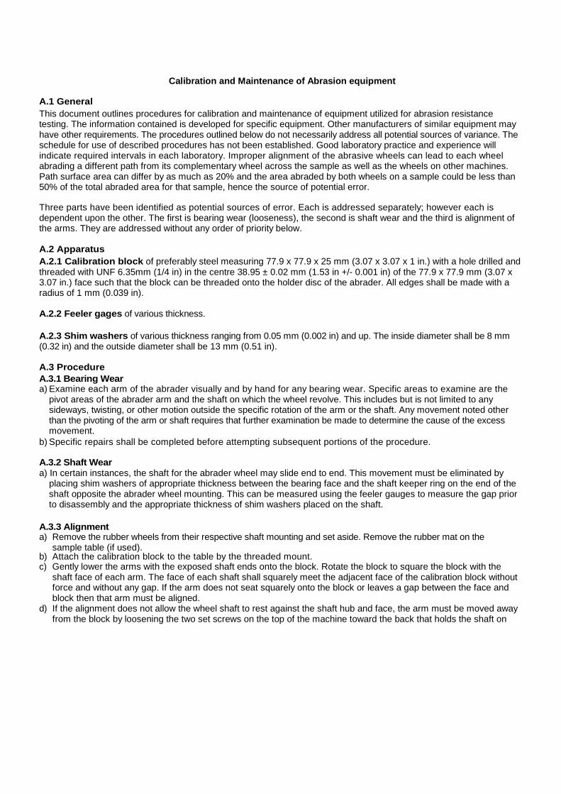
Calibration and Maintenance of Abrasion equipment
A.1 General This document outlines procedures for calibration and maintenance of equipment utilized for abrasion resistance testing. The information contained is developed for specific equipment. Other manufacturers of similar equipment may have other requirements. The procedures outlined below do not necessarily address all potential sources of variance. The schedule for use of described procedures has not been established. Good laboratory practice and experience will indicate required intervals in each laboratory. Improper alignment of the abrasive wheels can lead to each wheel abrading a different path from its complementary wheel across the sample as well as the wheels on other machines. Path surface area can differ by as much as 20% and the area abraded by both wheels on a sample could be less than 50% of the total abraded area for that sample, hence the source of potential error.
Three parts have been identified as potential sources of error. Each is addressed separately; however each is dependent upon the other. The first is bearing wear (looseness), the second is shaft wear and the third is alignment of the arms. They are addressed without any order of priority below.
A.2 Apparatus A.2.1 Calibration block of preferably steel measuring 77.9 x 77.9 x 25 mm (3.07 x 3.07 x 1 in.) with a hole drilled and threaded with UNF 6.35mm (1/4 in) in the centre 38.95 ± 0.02 mm (1.53 in +/- 0.001 in) of the 77.9 x 77.9 mm (3.07 x 3.07 in.) face such that the block can be threaded onto the holder disc of the abrader. All edges shall be made with a radius of 1 mm (0.039 in).
A.2.2 Feeler gages of various thickness.
A.2.3 Shim washers of various thickness ranging from 0.05 mm (0.002 in) and up. The inside diameter shall be 8 mm (0.32 in) and the outside diameter shall be 13 mm (0.51 in).
A.3 Procedure A.3.1 Bearing Wear a) Examine each arm of the abrader visually and by hand for any bearing wear. Specific areas to examine are the
pivot areas of the abrader arm and the shaft on which the wheel revolve. This includes but is not limited to any sideways, twisting, or other motion outside the specific rotation of the arm or the shaft. Any movement noted other than the pivoting of the arm or shaft requires that further examination be made to determine the cause of the excess movement.
b) Specific repairs shall be completed before attempting subsequent portions of the procedure.
A.3.2 Shaft Wear a) In certain instances, the shaft for the abrader wheel may slide end to end. This movement must be eliminated by
placing shim washers of appropriate thickness between the bearing face and the shaft keeper ring on the end of the shaft opposite the abrader wheel mounting. This can be measured using the feeler gauges to measure the gap prior to disassembly and the appropriate thickness of shim washers placed on the shaft.
A.3.3 Alignment a) Remove the rubber wheels from their respective shaft mounting and set aside. Remove the rubber mat on the
sample table (if used). b) Attach the calibration block to the table by the threaded mount. c) Gently lower the arms with the exposed shaft ends onto the block. Rotate the block to square the block with the
shaft face of each arm. The face of each shaft shall squarely meet the adjacent face of the calibration block without force and without any gap. If the arm does not seat squarely onto the block or leaves a gap between the face and block then that arm must be aligned.
d) If the alignment does not allow the wheel shaft to rest against the shaft hub and face, the arm must be moved away from the block by loosening the two set screws on the top of the machine toward the back that holds the shaft on
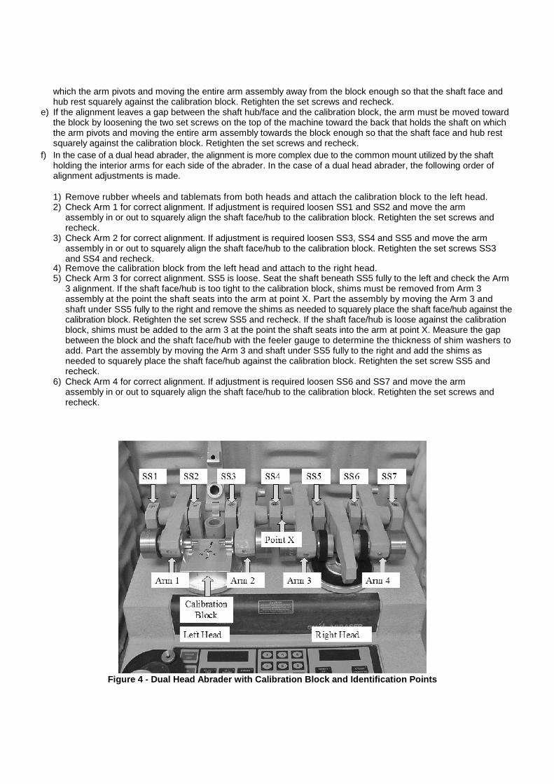
which the arm pivots and moving the entire arm assembly away from the block enough so that the shaft face and hub rest squarely against the calibration block. Retighten the set screws and recheck.
e) If the alignment leaves a gap between the shaft hub/face and the calibration block, the arm must be moved toward the block by loosening the two set screws on the top of the machine toward the back that holds the shaft on which the arm pivots and moving the entire arm assembly towards the block enough so that the shaft face and hub rest squarely against the calibration block. Retighten the set screws and recheck.
f) In the case of a dual head abrader, the alignment is more complex due to the common mount utilized by the shaft holding the interior arms for each side of the abrader. In the case of a dual head abrader, the following order of alignment adjustments is made.
1) Remove rubber wheels and tablemats from both heads and attach the calibration block to the left head. 2) Check Arm 1 for correct alignment. If adjustment is required loosen SS1 and SS2 and move the arm
assembly in or out to squarely align the shaft face/hub to the calibration block. Retighten the set screws and recheck.
3) Check Arm 2 for correct alignment. If adjustment is required loosen SS3, SS4 and SS5 and move the arm assembly in or out to squarely align the shaft face/hub to the calibration block. Retighten the set screws SS3 and SS4 and recheck.
4) Remove the calibration block from the left head and attach to the right head. 5) Check Arm 3 for correct alignment. SS5 is loose. Seat the shaft beneath SS5 fully to the left and check the Arm
3 alignment. If the shaft face/hub is too tight to the calibration block, shims must be removed from Arm 3 assembly at the point the shaft seats into the arm at point X. Part the assembly by moving the Arm 3 and shaft under SS5 fully to the right and remove the shims as needed to squarely place the shaft face/hub against the calibration block. Retighten the set screw SS5 and recheck. If the shaft face/hub is loose against the calibration block, shims must be added to the arm 3 at the point the shaft seats into the arm at point X. Measure the gap between the block and the shaft face/hub with the feeler gauge to determine the thickness of shim washers to add. Part the assembly by moving the Arm 3 and shaft under SS5 fully to the right and add the shims as needed to squarely place the shaft face/hub against the calibration block. Retighten the set screw SS5 and recheck.
6) Check Arm 4 for correct alignment. If adjustment is required loosen SS6 and SS7 and move the arm assembly in or out to squarely align the shaft face/hub to the calibration block. Retighten the set screws and recheck.
Figure 4 - Dual Head Abrader with Calibration Block and Identification Points


Figure 5 - Calibration Block with Arms Correctly Aligned

![CRWP flooring scoping study for CRA.ppt [Read-Only] · PDF fileLaminate Vinyl Ceramics Resin Wood Linoleum Rubber Carpet Laminate Vinyl Ceramics Resin Wood Linoleum Rubber. The construction](https://img.pdfslide.us/doc/110x75/5ab711d47f8b9ac10d8b53df/crwp-flooring-scoping-study-for-crappt-read-only-vinyl-ceramics-resin-wood-linoleum.jpg)