Embed Size (px)
Citation preview
Meriam Process Technologies www.meriam.com ph: 800.817.7849 fax: 216.281.0228Meriam Process Technologies www.meriam.com ph: 800.817.7849 fax: 216.281.0228106
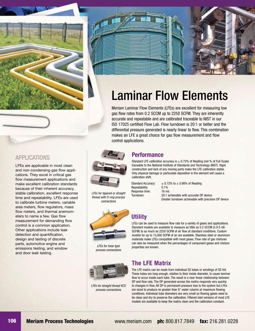
ApplicAtionsLFEs are applicable in most clean and non-condensing gas flow appli-cations. They excel in critical gas flow measurement applications and make excellent calibration standards because of their inherent accuracy, stable calibration, excellent response time and repeatability. LFEs are used to calibrate turbine meters, variable area meters, flow regulators, mass flow meters, and thermal anemom-eters to name a few. Gas flow measurement for demanding flow control is a common application. Other applications include leak detection and quantification, design and testing of discrete parts, automotive engine and emissions testing, and window and door leak testing.
laminar Flow ElementsMeriam Laminar Flow Elements (LFEs) are excellent for measuring low gas flow rates from 0.2 SCCM up to 2250 SCFM. They are inherently accurate and repeatable and are calibrated traceable to NIST in our ISO 17025 certified Flow Lab. Flow turndown is 20:1 or better and the differential pressure generated is nearly linear to flow. This combination makes an LFE a great choice for gas flow measurement and flow control applications.
Standard LFE calibration accuracy is ± 0.72% of Reading (not % of Full Scale) traceable to the National Institute of Standards and Technology (NIST). Rigid construction and lack of any moving parts make the LFE calibration stable. Only physical damage or particulate deposition in the element will cause a calibration shift.
Performance
LFEs can be used to measure flow rate for a variety of gases and applications. Standard models are available to measure as little as 0.2 SCCM (5.9 E-06 SCFM) to as much as 2250 SCFM of air flow at standard conditions. Custom models for up to 15,000 SCFM of air are available. Stainless steel or aluminum materials make LFEs compatible with most gases. Flow rate of gas mixtures can also be measured when the percentages of component gases and mixture properties are known.
Utility
The LFE matrix can be made from individual SS tubes or windings of SS foil. These tubes are long enough, relative to their inside diameter, to cause laminar flow to occur inside each tube. The result is a near linear relationship between DP and flow rate. The DP generated across the matrix responds very quickly to changes in flow. All DP is permanent pressure loss to the system but LFEs are sized to produce no greater than 8” water column at maximum flowing conditions. Individual tube diameters are very small so flowing gases need to be clean and dry to preserve the calibration. Filtered inlet versions of most LFE models are available to keep the matrix clean and the calibration constant.
The LFE Matrix
Standard Accuracy: ± 0.72% to ± 0.86% of ReadingRepeatability: 0.1%Response time: 16 msTurndown: 20:1 achievable with accurate DP device Greater turndown achievable with precision DP device
LFEs for tapered or straight thread with O-ring process
connections
LFEs for hose type process connections
LFEs for straight thread VCO process connections
Laminar Flow ElementsLaminar Flow Elements 107
Calibration and Accuracy
*Accuracy Levels Available: Commercial Calibration ± 0.72% of Actual Reading†
Master Calibration ± 0.64% of Actual Reading††
Independent Lab Calibration ± 0.50% of Actual Reading or better, consult factory
† ± 0.86% Reading for full scale flow of 1000 SCFM or higher †† ± 0.70% Reading for full scale flow of 1000 SCFM or higher
LFEs for flanged process connections
Filtered inlet LFE’s available for intake
measurment applications
• LFEforflowsof400SCFMto2250SCFM• Nostraightrunrequirementsupstreamofinlinefilterassembly• Mechanismallowsendusertochangefilterwithvirtuallynoeffectonthe calibration curve (no more than ±0.3%)
50MC2-T SeriesLFS-1 Flow Measurement SystemThe LFS-1 Flow Measurement System for Meriam LFEs provides a superior gas flow measurement solution. The integral flow computer makes real time corrections for changes in differential pressure, static pressure, temperature and relative humidity to provide the most accurate results possible. All LFS packages include complete instrumentation, system calibration and NIST traceable documentation.
Meriam LFEs are calibrated with air at atmospheric conditions referenced to 29.92” mercury absolute (760mm Hg. Abs.) and 70ºF (21.1ºC). Each completed element is calibrated and traceable to the National Institute of Standards and Technology. Our Special Calibration Procedure #A-33544 is designed to meet the basic requirements of MIL-STD-45662A, ANSI Z540, 10CFR50 and MIL-Q-9858A.
Meriam LFEs are supplied with a reproducible flow curve in terms of SCFM versus inches of water differential pressure. Correction factors are included to cover an inlet pressure range from 26 to 36” Hg Abs. and an inlet temperature from 50ºF to 150ºF. For special flow applications, contact Meriam with complete flow information. The rated accuracy* of all Meriam LFEs is percentage of actual reading; not the much wider percentage of full scale flow rate tolerance of other devices.
Meriam Process Technologies www.meriam.com ph: 800.817.7849 fax: 216.281.0228108
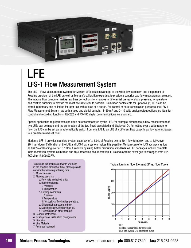
lFs-1 Flow Measurement systemThe LFS-1 Flow Measurement System for Meriam LFEs takes advantage of the wide flow turndown and the percent of Reading precision of the LFE, as well as Meriam’s calibration expertise, to provide a superior gas flow measurement solution. The integral flow computer makes real time corrections for changes in differential pressure, static pressure, temperature and relative humidity to provide the most accurate results possible. Calibration coefficients for up to five (5) LFEs can be stored in memory and called up for later use with a push of a button. For control or data transmission purposes, the LFS-1 Flow Measurement System has both analog and digital outputs. 4–20 mA and 0–10 volts analog output options are ideal for control and recording functions. RS-232 and RS-485 digital communications are standard.
Special application requirements can often be accommodated by the LFS. For example, simultaneous flow measurement of two LFEs can be made and the summation of the two flows calculated and displayed. Or, for testing over a wide range for flow, the LFS can be set up to automatically switch from one LFE to an LFE of a different flow capacity as flow rate increases to a predetermined set point.
Meriam’s LFS-1 provides standard system accuracy of ± 1.0% of Reading over a 10:1 flow turndown and ± 1.1% over 20:1 turndown. Calibration of the LFE and LFS-1 as a system makes this possible. Meriam can offer LFS accuracy as low as 0.60% of Reading over a 10:1 flow turndown by using better calibration standards. All LFS packages include complete instrumentation, system calibration and NIST traceable documentation. LFEs and systems cover gas flow ranges from 0.2 SCCM to 15,000 SCFM.
lFE
Typical Laminar Flow Element DP vs. Flow Curve
KEYRed line: Straight line for referenceBlue line: Typical LFE calibration curve
To provide the accurate answers you need in the shortest amount of time, please provide us with the following ordering data:1. Model number.2. Flowing gas data;
a. Flow rate in desired units. b. Base conditions.
i. Pressureii. Temperature
c. Flowing conditionsi. Pressureii. Temperatureiii. Viscosity at flowing temperature.
d. Differential at maximum flow. e. Specific gravity, if other than air. f. Flowing gas, if other than air.
3. Readout instrument.4. Description of installation configuration.5. Line size.6. Line Material.7. Accuracy required

Laminar Flow Elements
LFE
109
Model Number & Description Tube Size
UNF x VCO process conn., ¼” SAE J1926
port, O-ring boss DP conn.
Nominal Air Flow Range(29.92” Hg. Abs. & 70ºF)
Max. DP In. H2O
Nominal Air Flow Range(760 MM Hg. Abs. & 21.1ºC)
Max DPMM H2O
SCFM* PPM CC/MIN* LPM* Kg/M
50MT10Utilizes stainless steel capillary tubes cemented into a stainless steel body. Inlet and outlet connections are VCO type. Differential pressure connections are ¼” SAE J1926 port, O-ring boss.
¼” 50MT10-8 0.00019 1.42x10⁻⁵ 4” 5.38 0.00538 6.44x10⁻⁶ 101.6
¼” 50MT10-7 0.00062 4.64x10⁻⁵ 4” 17.5 0.0175 2.10x10⁻⁵ 101.6
¼” 50MT10-6 0.000124 9.28x10⁻⁵ 4” 35.1 0.0351 4.21x10⁻⁵ 101.6
¼” 50MT10-5 0.0025 1.87x10⁻⁴ 4” 70.8 0.0708 8.48x10⁻⁵ 101.6
¼” 50MT10-4 0.0046 3.45x10⁻⁴ 4” 130 0.130 1.56x10⁻⁴ 101.6
¼” 50MT10-3 0.0081 6.07x10⁻⁴ 4” 229 0.229 2.75x10⁻⁴ 101.6
¼” 50MT10-2 0.0149 0.00112 4” 422 0.422 5.06x10⁻⁴ 101.6
¼” 50MT10-1 0.046 0.00344 4” 1300 1.30 0.00156 101.6
50MT10All stainless steel unit with fused matrix. Inlet and outlet connections are VCO type. Differential pressure connections are ¼” SAE J1926 port, O-ring boss.
½” 50MT10-14 0.10 0.00749 8” 2830 2.83 0.00339 203.2
½” 50MT10-13 0.18 0.0135 8” 5100 5.10 0.0061 203.2
½” 50MT10-12 0.38 0.0285 8” 10700 10.8 0.0129 203.2
½” 50MT10-11 0.70 0.0524 8” 19800 19.8 0.0237 203.2
½” 50MT10-10 1.60 0.120 8” 45300 45.3 0.0543 203.2
¾” 50MT10-9 3.00 0.225 8” 85000 85.0 0.102 203.2
50MT20All stainless steel unit with fused matrix. Inlet and outlet connections are VCO type. Differential pressure connec-tions are ¼” SAE J1926 port, O-ring boss.
1” 50MT20-1 7.5 0.562 8” 2.12x10⁵ 212 0.254 203.2
1½” 50MT20-1½ 22 1.65 8” 6.23x10⁵ 6.23 0.746 203.2
2” 50MT20-2 40 3.00 8” 1.13x10⁶ 1130 1.357 203.2
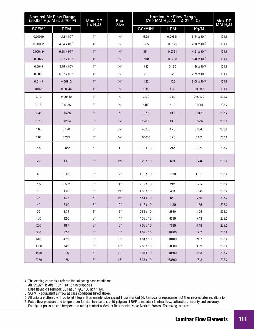
NOTES:1. The flows and differential pressure rating of production units are subject to a variation of plus or minus 10% from the nominal values listed above.2. Each LFE unit is calibrated with air to Meriam flow standards which are traceable to the National Bureau of Standards. Meriam calibration flow curves are furnished with each unit.3. A special service is available for those Meriam LFE units which are governed by quality programs requiring periodic recalibration. The Special Calibration Procedure A-33544 is designed to meet the basic requirements of 10CFR50, ANSI-Z540-I & ML-Q-9858A. Contact Meriam direct for information.4. The catalog capacities refer to the following base conditions: Air, 29.92” Hg Abs., 70º F, 181.87 micropoises. Base Reynold’s Number: 300 at 8” H2O, 150 at 4” H2O.5. SCFM* - Equivalent air flow at base conditions listed above.6. All units are offered with optional integral filter on inlet side except those marked (x). Removal or replacement of filter necessitates recalibration.7. Rated flow pressure and temperature for standard units are 30 psig and 150ºF to maintain laminar flow, calibration, linearity and accuracy. For higher pressure and temperature rating contact a Meriam Representative, or Meriam Process Technologies direct.
For sizing information, please consult Meriam’s Technical / Sizing Bulletin F/N 501:215TECH or contact Meriam directly.
Threaded Connections Available on LFEs
FISO 7/1 Pipe ConnectionNPT Pipe Connection UNF x VCO
Tubing x VCO face seal
SAE J1926Tubing x straight thread / O-ring
DIN 3852 Part 2Tubing x straight thread / O-ring

Meriam Process Technologies www.meriam.com ph: 800.817.7849 fax: 216.281.0228
Model Number & Description Pipe Size
NPT tapered thread
FISO 7/1 tapered thread
SAE J1926 straight
thread w/ O-ring
DIN3852 Part 2
straight thread w/
O-ring
50MK10Utilizes stainless steel capillary tubes cemented into a stainless steel body. Inlet, outlet and differential pressure connections are ¼”.
¼” 50MK10-8 50MK10-8MT 50MK10-8S 50MK10-8MS
¼” 50MK10-7 50MK10-7MT 50MK10-7S 50MK10-7MS
¼” 50MK10-6 50MK10-6MT 50MK10-6S 50MK10-6MS
¼” 50MK10-5 50MK10-5MT 50MK10-5S 50MK10-5MS
¼” 50MK10-4 50MK10-4MT 50MK10-4S 50MK10-4MS
¼” 50MK10-3 50MK10-3MT 50MK10-3S 50MK10-3MS
¼” 50MK10-2 50MK10-2MT 50MK10-2S 50MK10-2MS
¼” 50MK10-1 50MK10-1MT 50MK10-1S 50MK10-1MS
Model 50MJ10All stainless steel unit with fused matrix. Differential pressure connections are ¼”. Line connections ½” NPT, except Type 9 which has ¾” NPT.
½” 50MJ10-14 50MJ10-14MT 50MJ10-14S 50MJ10-14MS
½” 50MJ10-13 50MJ10-13MT 50MJ10-13S 50MJ10-13MS
½” 50MJ10-12 50MJ10-12MT 50MJ10-12S 50MJ10-12MS
½” 50MJ10-11 50MJ10-11MT 50MJ10-11S 50MJ10-11MS
½” 50MJ10-10 50MJ10-10MT 50MJ10-10S 50MJ10-10MS
¾” 50MJ10-9 50MJ10-9MT 50MJ10-9S 50MJ10-9MS
50MW20All stainless steel welded unit with fused matrix. Line connections are threaded. Differential pressure connections are ¼”.
1” 50MW20-1 50MW20-1MT 50MW20-1S 50MW20-1MS
1½” 50MW20-1 1/2 50MW20-1 1/2MT 50MW20-1 1/2S 50MW20-1 1/2MS
2” 50MW20-2 50MW20-2MT 50MW20-2S 50MW20-2MS
50MH10All stainless steel welded unit with fused matrix. Line connections are tapered ends (no threads) for hose connection. Differential pressure connections are ¼” NPT.
1” 50MH10-1 ----- ----- -----
1¼” 50MH10-1 1/4 ----- ----- -----
1½” 50MH10-1 1/2 ----- ----- -----
2” 50MH10-2 ----- ----- -----
3” 50MH10-3 ----- ----- -----
4” 50MH10-4 ----- ----- -----
5” 50MH10-5 ----- ----- -----
6” 50MH10-6 ----- ----- -----
8” 50MH10-8 (x) ----- ----- -----
10” 50MH10-10 (x) ----- ----- -----
12” 50MH10-12 (x) ----- ----- -----
16” 50MH10-16 (x) ----- ----- -----
NOTES:1. The flows and differential pressure rating of production units are subject to a variation of plus or minus 10% from the nominal values listed above.2. Each LFE unit is calibrated with air to Meriam flow standards which are traceable to the National Bureau of Standards. Meriam calibration flow curves are furnished with each unit.3. A special service is available for those Meriam LFE units which are governed by quality programs requiring periodic recalibration. The Special Calibration Procedure A-33544 is designed to meet the basic requirements of 10CFR50, ANSI-Z540-I & ML-Q-9858A. Contact Meriam direct for information.
110
Laminar Flow Elements
Nominal Air Flow Range(29.92” Hg. Abs. & 70º F) Max. DP
In. H2OPipe Size
Nominal Air Flow Range(760 MM Hg. Abs. & 21.1º C) Max DP
MM H2OSCFM* PPM CC/MIN* LPM* Kg/M
0.00019 1.42 x 10⁻⁵ 4” ¼” 5.38 0.00538 6.44 x 10⁻⁶ 101.6
0.00062 4.64 x 10⁻⁵ 4” ¼” 17.5 0.0175 2.10 x 10⁻⁵ 101.6
0.000124 9.28 x 10⁻⁵ 4” ¼” 35.1 0.0351 4.21 x 10⁻⁵ 101.6
0.0025 1.87 x 10⁻⁴ 4” ¼” 70.8 0.0708 8.48 x 10⁻⁵ 101.6
0.0046 3.45 x 10⁻⁴ 4” ¼” 130 0.130 1.56 x 10⁻⁴ 101.6
0.0081 6.07 x 10⁻⁴ 4” ¼” 229 .229 2.75 x 10⁻⁴ 101.6
0.0149 0.00112 4” ¼” 422 .422 5.06 x 10⁻⁴ 101.6
0.046 0.00344 4” ¼” 1300 1.30 0.00156 101.6
0.10 0.00749 8” ½” 2830 2.83 0.00339 203.2
0.18 0.0135 8” ½” 5100 5.10 0.0061 203.2
0.38 0.0285 8” ½” 10700 10.8 0.0129 203.2
0.70 0.0524 8” ½” 19800 19.8 0.0237 203.2
1.60 0.120 8” ½” 45300 45.3 0.0543 203.2
3.00 0.225 8” ¾” 85000 85.0 0.102 203.2
7.5 0.562 8” 1” 2.12 x 10⁵ 212 0.254 203.2
22 1.65 8” 1½” 6.23 x 10⁵ 623 0.746 203.2
40 3.00 8” 2” 1.13 x 10⁶ 1130 1.357 203.2
7.5 0.562 8” 1” 2.12 x 10⁵ 212 0.254 203.2
16 1.20 8” 1¼” 4.53 x 10⁵ 453 0.543 203.2
23 1.72 8” 1½” 6.51 x 10⁵ 651 .780 203.2
40 3.00 8” 2” 1.13 x 10⁶ 1130 1.35 203.2
90 6.74 8” 3” 2.55 x 10⁶ 2550 3.05 203.2
160 12.0 8” 4” 4.53 x 10⁶ 4530 5.43 203.2
250 18.7 8” 5” 7.08 x 10⁶ 7080 8.48 203.2
360 27.0 8” 6” 1.02 x 10⁷ 10200 12.2 203.2
640 47.9 8” 8” 1.81 x 10⁷ 18100 21.7 203.2
1000 74.9 8” 10” 2.83 x 10⁷ 28300 33.9 203.2
1440 108 8” 12” 4.07 x 10⁷ 40800 48.8 203.2
2250 168 8” 16” 6.37 x 10⁷ 63700 76.3 203.2
4. The catalog capacities refer to the following base conditions: Air, 29.92” Hg Abs., 70º F, 181.87 micropoises. Base Reynold’s Number: 300 at 8” H2O, 150 at 4” H2O.5. SCFM* - Equivalent air flow at base conditions listed above.6. All units are offered with optional integral filter on inlet side except those marked (x). Removal or replacement of filter necessitates recalibration.7. Rated flow pressure and temperature for standard units are 30 psig and 150ºF to maintain laminar flow, calibration, linearity and accuracy. For higher pressure and temperature rating contact a Meriam Representative, or Meriam Process Technologies direct.
111

112
Model Number & Description Pipe Size
NPT tapered thread
FISO 7/1 tapered thread
SAE J1926 straight
thread w/ O-ring
DIN3852 Part 2
straight thread w/
O-ring
50MY15All stainless steel welded unit with fused matrix. Line connections are 150 lb ANSI flanges. Differential pressure connections are ¼” NPT.
2½” 50MY15-2 1/2 ----- ----- -----
3” 50MY15-3 ----- ----- -----
4” 50MY15-4 ----- ----- -----
5” 50MY15-5 ----- ----- -----
6” 50MY15-6 ----- ----- -----
8” 50MY15-8 (x) ----- ----- -----
10” 50MY15-10 (x) ----- ----- -----
12” 50MY15-12 (x) ----- ----- -----
16” 50MY15-16 (x) ----- ----- -----
50MR2Aluminum housing for low pressure applications. Line connections are 150 lb ANSI flanges. Differential pressure connections ¼” hose barb.
2” 50MR2-2 ----- ----- -----
4” 50MR2-4 ----- ----- -----
6” 50MR2-6 ----- ----- -----
8” 50MR2-8 ----- ----- -----
50MC2 Aluminum housing for low pressure applications. Inlet and outlet are for hose type connections. Differential pressure connections ¼” hose barb.
2”I.D. 50MC2-2 ----- ----- -----
4”I.D. 50MC2-4 ----- ----- -----
6”I.D. 50MC2-6 ----- ----- -----
8”I.D. 50MC2-8 ----- ----- -----
50MC2-4T / 50MC2-6T / 50MC2-8TAluminum housing featuring inline filter for low pressure applications. No straight runs required on the inlet side. Outlet designed for a pipe or hose connection. Differential pressure connections 1/4” hose barb.
4”I.D. 50MC2-4T ----- ----- -----
6”I.D. 50MC2-6T ----- ----- -----
8”I.D. 50MC2-8T ----- ----- -----
NOTES:1. The flows and differential pressure rating of production units are subject to a variation of plus or minus 10% from the nominal values listed above.2. Each LFE unit is calibrated with air to Meriam flow standards which are traceable to the National Bureau of Standards. Meriam calibration flow curves are furnished with each unit.3. A special service is available for those Meriam LFE units which are governed by quality programs requiring periodic recalibration. The Special Calibration Procedure A-33544 is designed to meet the basic requirements of 10CFR50, ANSI-Z540-I & ML-Q-9858A. Contact Meriam direct for information.
Meriam Process Technologies www.meriam.com ph: 800.817.7849 fax: 216.281.0228112

Laminar Flow Elements 113
Nominal Air Flow Range(29.92” Hg. Abs. & 70º F) Max. DP
In. H2OPipe Size
Nominal Air Flow Range(760 MM Hg. Abs. & 21.1º C) Max DP
MM H2OSCFM* PPM CC/MIN* LPM* Kg/M
60 4.50 8” 2½” 1.69 x 10⁶ 1700 2.03 203.2
90 6.74 8” 3” 2.55 x 10⁶ 2550 3.05 203.2
160 12.0 8” 4” 4.53 x 10⁶ 4530 5.43 203.2
250 18.7 8” 5” 7.08 x 10⁶ 7080 8.48 203.2
360 27.0 8” 6” 1.02 x 10⁷ 10200 12.2 203.2
640 47.9 8” 8” 1.81 x 10⁷ 18100 21.7 203.2
1000 74.9 8” 10” 2.83 x 10⁷ 28300 33.9 203.2
1440 108 8” 12” 4.07 x 10⁷ 40800 48.8 203.2
2250 169 8” 16” 6.37 x 10⁷ 63700 76.6 203.2
100 7.49 8” 2” 2.83 x 10⁶ 2830 3.39 203.2
400 30.0 8” 4” 1.13 x 10⁷ 11300 13.6 203.2
1000 74.9 8” 6” 2.83 x 10⁷ 28300 33.9 203.2
2250 168 8” 8” 6.37 x 10⁷ 63700 76.3 203.2
100 7.49 8” 2”I.D. 2.83 x 10⁶ 2830 3.39 203.2
400 30.0 8” 4”I.D. 1.13 x 10⁷ 11300 13.6 203.2
1000 74.9 8” 6”I.D. 2.83 x 10⁷ 28300 33.9 203.2
2250 168 8” 8”I.D. 6.37 x 10⁷ 63700 76.3 203.2
400 30.0 8” 4”I.D. 1.13 x 10⁷ 11300 13.6 203.2
1000 74.9 8” 6”I.D. 2.83 x 10⁷ 28300 33.9 203.2
2250 168 8” 8”I.D. 6.37 x 10⁷ 63700 76.3 203.2
4. The catalog capacities refer to the following base conditions: Air, 29.92” Hg Abs., 70º F, 181.87 micropoises. Base Reynold’s Number: 300 at 8” H2O, 150 at 4” H2O.5. SCFM* - Equivalent air flow at base conditions listed above.6. All units are offered with optional integral filter on inlet side except those marked (x). Removal or replacement of filter necessitates recalibration.7. Rated flow pressure and temperature for standard units are 30 psig and 150ºF to maintain laminar flow, calibration, linearity and accuracy. For higher pressure and temperature rating contact a Meriam Representative, or Meriam Process Technologies direct.


![Instruments [Meriam]](https://img.pdfslide.us/doc/110x75/577d20701a28ab4e1e92e288/instruments-meriam.jpg)