Embed Size (px)
Citation preview
LOH-CD REV A 1
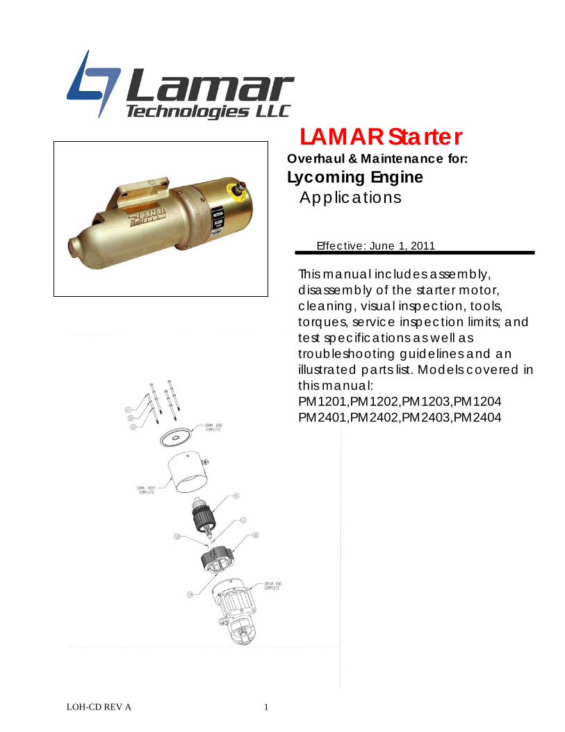
LAMAR Starter Overhaul & Maintenance for:
Lycoming Engine Applications
Effective: June 1, 2011
This manual includes assembly, disassembly of the starter motor, cleaning, visual inspection, tools, torques, service inspection limits; and test specifications as well as troubleshooting guidelines and an illustrated parts list. Models covered in this manual: PM1201,PM1202,PM1203,PM1204 PM2401,PM2402,PM2403,PM2404
LOH-CD REV A 2
Table of Contents
FIG 1: STARTER EXPLODED VIEW ................................................................................. 3
FIG 2: STARTER DRIVE END EXPLODED VIEW .............................................................. 4 DISASSEMBLY PROCEDURE ............................................................................................ 5
CLEANING AND VISUAL INSPECTION ........................................................................... 6
ASSEMBLY PROCEDURE ................................................................................................ 7
TOOLS, TORQUES, SERVICE INSPECTION LIMITS AND TEST SPECIFICATIONS ............ 20
NO LOAD & TORQUE TEST ............................................................................................ 21
TROUBLESHOOTING AND MAINTAINING STARTER DRIVE .......................................... 22 SERVICE INSTRUCTION LSI-001……………………………………………………………...23 PM1201-OHK OVERHAUL KIT, PM1201/PM1202 ....................................................... 24
PM2401-OHK OVERHAUL KIT, PM2401/PM2402 ....................................................... 26
PM1203-OHK OVERHAUL KIT, PM1203 ..................................................................... 28
PM2403-OHK OVERHAUL KIT, PM2403 ..................................................................... 30
PM1204-OHK OVERHAUL KIT, PM1204 ..................................................................... 32
PM2404-OHK OVERHAUL KIT, PM2404 ..................................................................... 34
CONTACT INFORMATION…………………………………………...………………...…….36
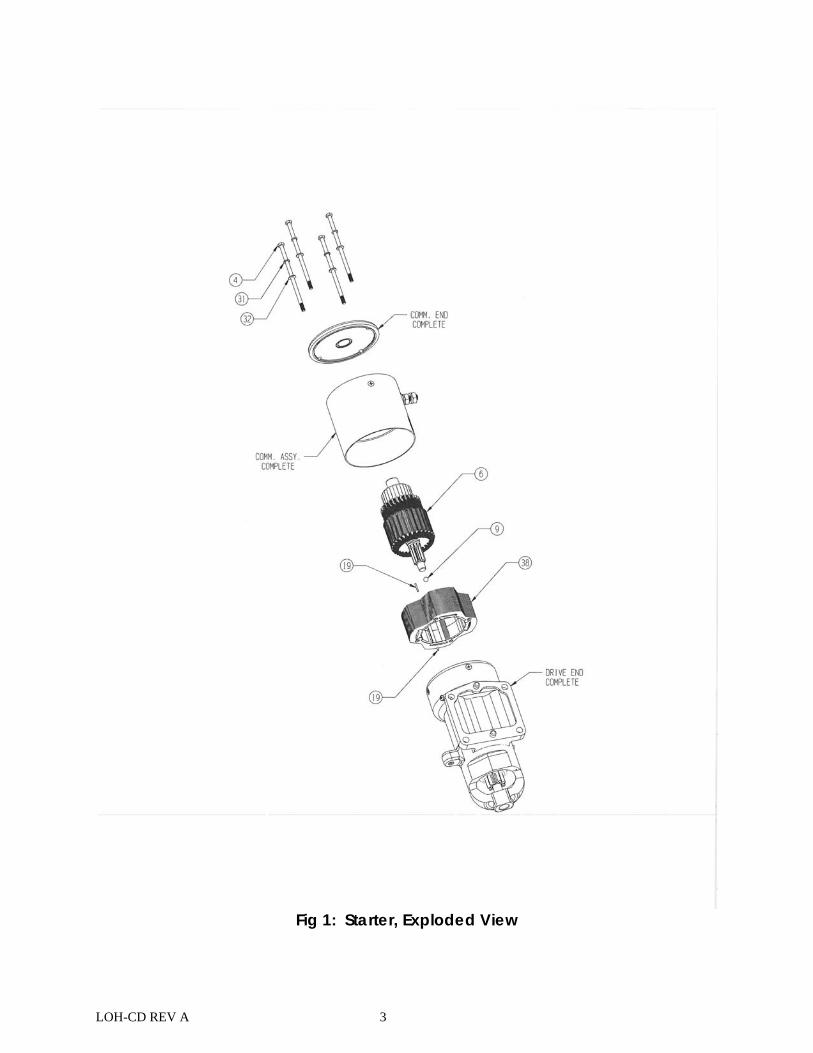
LOH-CD REV A 3
Fig 1: Starter, Exploded View
LOH-CD REV A 4
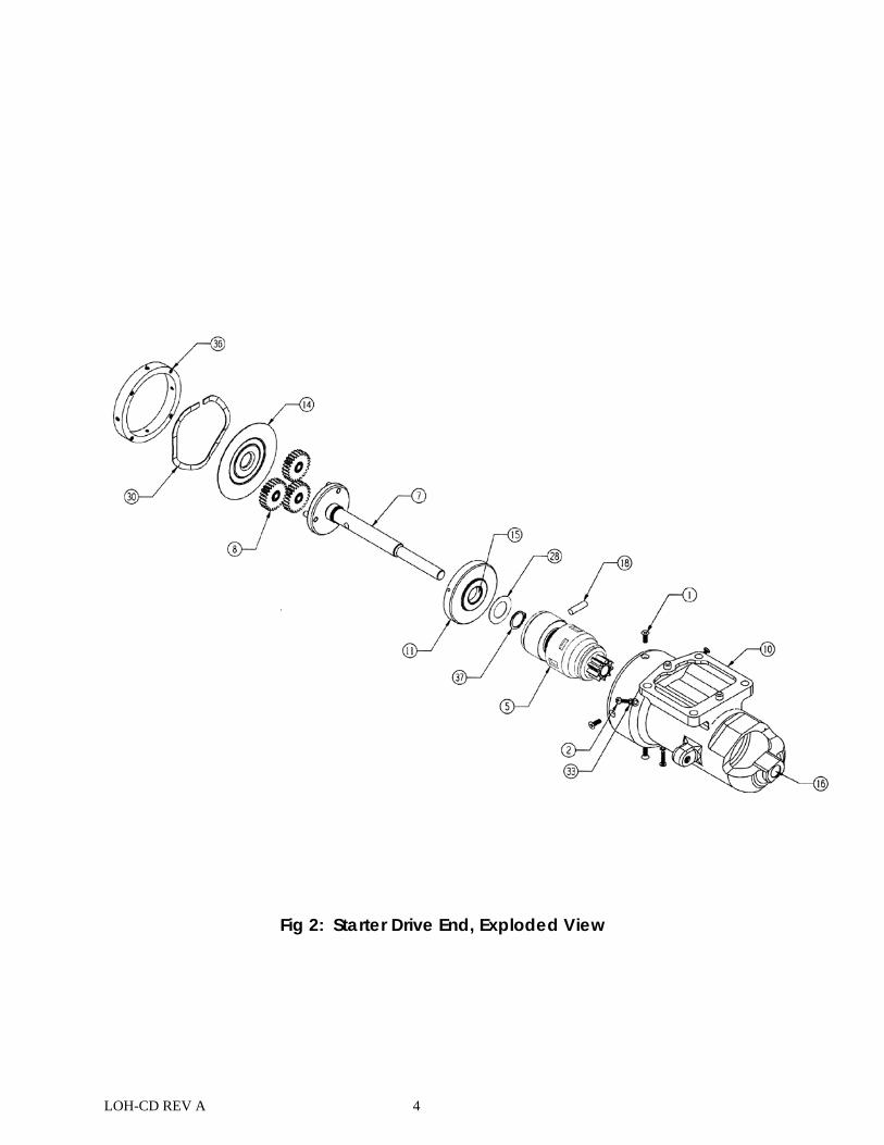
Fig 2: Starter Drive End, Exploded View
LOH-CD REV A 5
DISASSEMBLY PROCEDURE
1) Separate the comm. assy. by removing four Thru-bolts. (#4). (see figure 1) 2) Remove comm. end assembly (comm. end complete) (see figure 1) 3) Remove Bearing (#17) from comm. end (#13) and discard bearing. (see figure 6) 4) Remove item comm. assy. Complete. In most cases the comm. assy. will
separate from the nose case with the Flux Ring assembly (#38) and armature assembly (#6). Remove armature (#6) from comm. Assy. by pushing Commutator end of the shaft with thumbs until it is free. (see figure 1)
5) Remove flux ring assembly (#38) from comm. assy. complete by pushing from the comm. end of the starter. It may be necessary to
gently tap the flux ring from the brush end of the comm. assy. With a non metallic punch or a soft faced hammer to get it started. Pay attention not to damage or break the flux ring pins (#19). These pins are included in kit, if replacement is necessary. (see figure1)
6) From the comm. assy. complete remove brushes (#24&25), brush bracket (#21), brush spring (#22) and related hardware items (#2, 29&35) and discard. (see fig 12&13)
7) Remove and discard four screws (#1) from the Anchor Ring (#36). Remove the Anchor Ring (#36), Wave Washer (#30), Grease Shield (#14) Planetary Gears (#8). Discard planetary gears. (see figure 2)
8) Remove and discard the three screws (#2) and washers (#33) from Drive End. (see figure 2)
9) To dislodge the shaft assembly from housing tap open end of casting
on a solid wood surface with enough force to dislodge shaft assembly. 10) Remove and discard Drive End Housing Bushing (#16). (see figure 2) 11) Remove Starter Drive Pin and discard (#18). To remove, compress
Starter Drive to gain access to pin for removal. Remove and discard Starter Drive (#5). (see figure 2)
12) Remove and discard Snap Ring (#37) and Thrust Washer (#28) from
shaft. (see figure 2) 13) Remove Intermediate Shaft Support (#11) then remove and discard
Bushing (#15). (see figure 2)
LOH-CD REV A 6
CLEANING AND VISUAL INSPECTION
NOTES: Clean all parts to ensure all grease, oil and foreign materials are removed. Use of
Stoddard Solvent Federal Specification CS3-40 or equivalent is recommended. Do not soak armature or Flux Ring, blow dry with compressed air.
Do not use Carbon Tetrachloride when cleaning the Motor section. Use standard aircraft inspection techniques to determine
serviceability of Starter components. Abnormal wear, cracks, warping or damage are cause for
rejection. Wear beyond the limits shown in service inspection limits is also
cause for rejection. If starter has #8 Thru Bolts (fig1#4, 31, 32), OHK-0003 can be ordered
to upgrade to current standard (#10 thru bolts). This will include hardware and Anchor Ring.
1) Inspect Flux Ring Magnets for chipping and, or separation. Replace the Flux
Ring Assembly if this occurs. 2) Armature Assembly: Make certain to remove carbon or copper particles
imbedded in the insulation material between the commutator bars. Inspect the Armature shaft for signs of scoring, galling, signs of over heating or other damage. Inspect gear end of shaft for excessive wear. Replace armature as necessary. Commutator: Replace Armature assembly if any high or delaminated commutator bars are found. Inspect the contact surface of the Commutator. Satisfactory condition is indicated by an even, highly burnished copper color. If the contact surface is rough, pitted, scored, or darkened by a hardened film of carbon or oil which cleaning failed to remove, the Commutator must be resurfaced. (Refer to Service Inspection Limits). Use Scotch-Brite to clean armature and commutator.
3) Output Shaft: Inspect output Shaft pins), which support planetary gears (#8)
for excessive wear. (Refer to Service Inspection limits, pg.21). Inspect output Shaft bushing for uneven or excessive wear. (Refer to Service Inspection Limits). If either pins or bushing are out of tolerance, the output shaft must be replaced. (see figures 9&10)
4) Starter Nose Assembly: Inspect Ring Gear for play or excessive tooth wear.
Inspect Engine Pad pins for signs of being loose or missing. Replace Starter Nose Assembly if either of these happens. Inspect nose casting (#10) for cracks, unapproved modifications, or corrosion, replace if any of these conditions are found. (see figures 3,9, &10)
LOH-CD REV A 7
5) Intermediate Shaft Support: Clean and inspect Intermediate Shaft Support for stripped threads and general condition. Replace as necessary. (see figure 7)
6) Threaded Anchor Ring: Clean and inspect Threaded Anchor Ring (#36) for stripped threads, warping, and general condition. Replace as necessary. Refer to “Notes” for upgraded bolt size. (see figure 11)
LOH-CD REV A 8
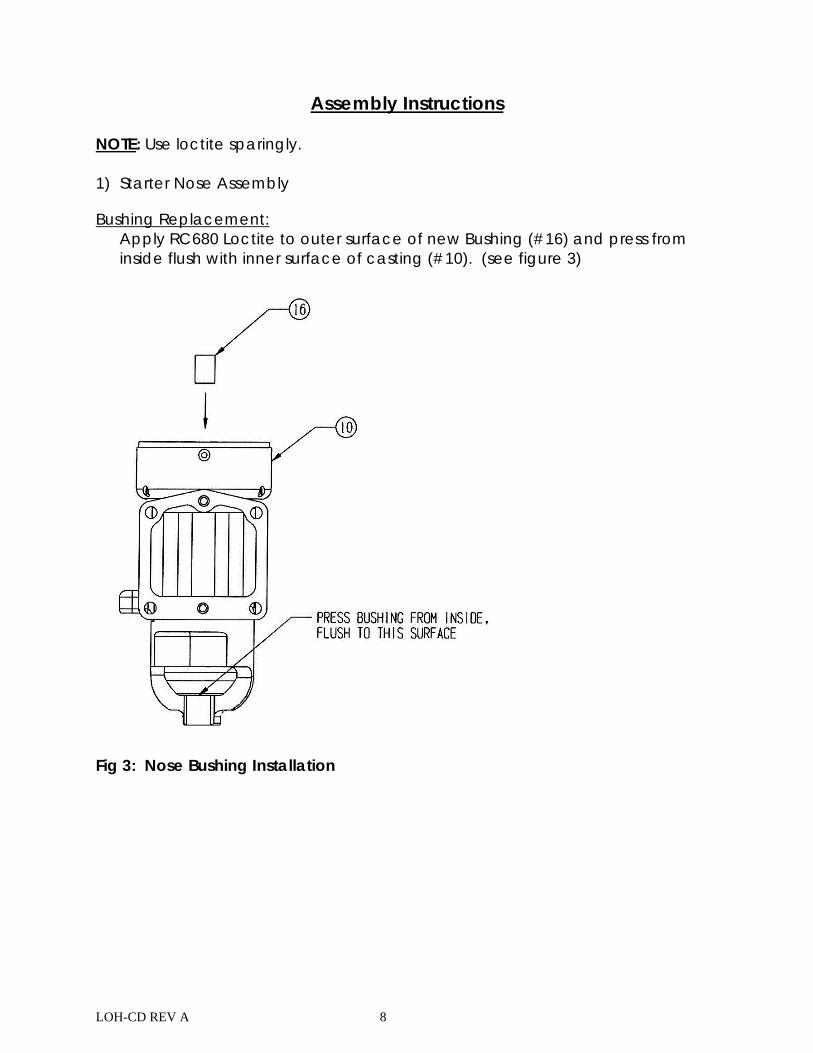
Assembly Instructions
NOTE: Use loctite sparingly. 1) Starter Nose Assembly Bushing Replacement:
Apply RC680 Loctite to outer surface of new Bushing (#16) and press from inside flush with inner surface of casting (#10). (see figure 3)
Fig 3: Nose Bushing Installation
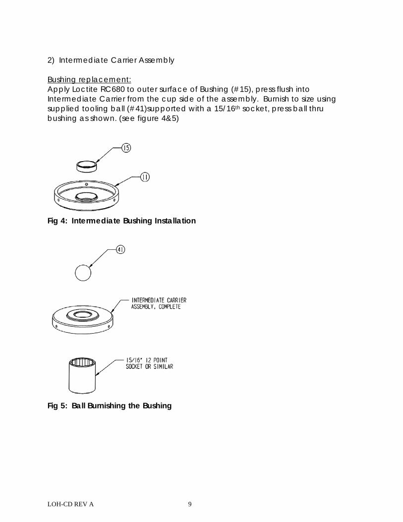
LOH-CD REV A 9
2) Intermediate Carrier Assembly Bushing replacement: Apply Loctite RC680 to outer surface of Bushing (#15), press flush into Intermediate Carrier from the cup side of the assembly. Burnish to size using supplied tooling ball (#41)supported with a 15/16th socket, press ball thru bushing as shown. (see figure 4&5)
Fig 4: Intermediate Bushing Installation
Fig 5: Ball Burnishing the Bushing
LOH-CD REV A 10
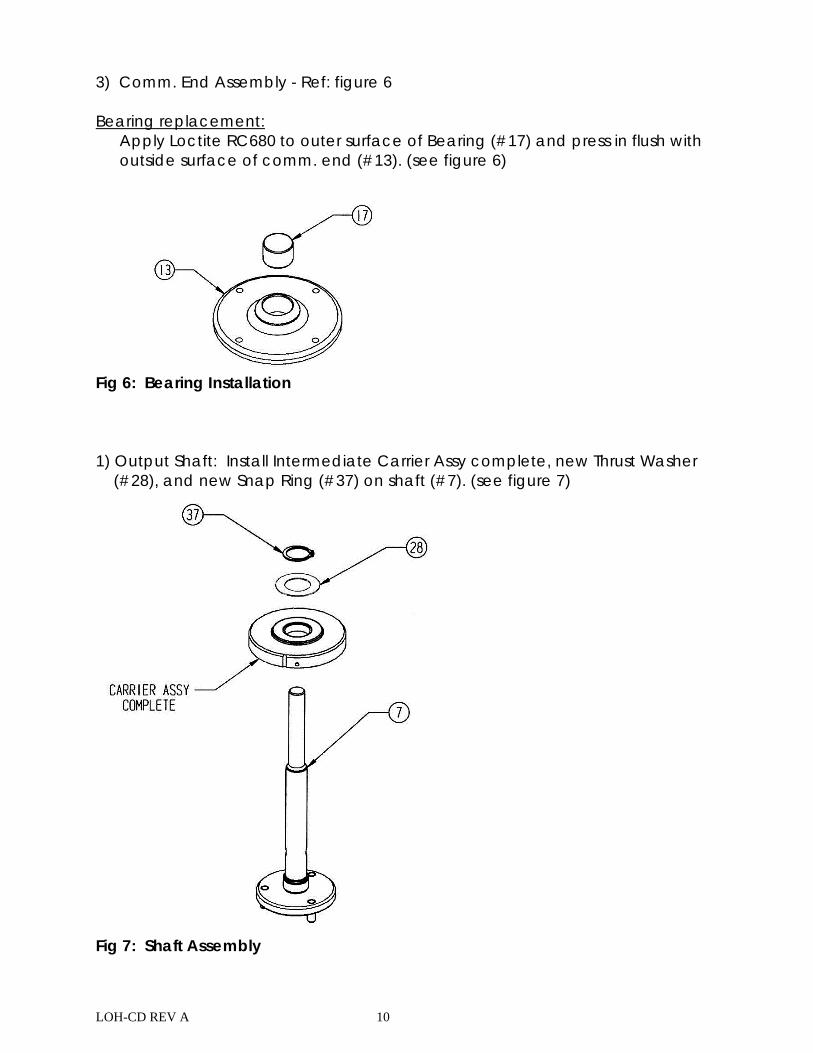
3) Comm. End Assembly - Ref: figure 6 Bearing replacement:
Apply Loctite RC680 to outer surface of Bearing (#17) and press in flush with outside surface of comm. end (#13). (see figure 6)
Fig 6: Bearing Installation 1) Output Shaft: Install Intermediate Carrier Assy complete, new Thrust Washer
(#28), and new Snap Ring (#37) on shaft (#7). (see figure 7)
Fig 7: Shaft Assembly
LOH-CD REV A 11
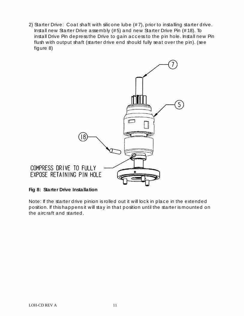
2) Starter Drive: Coat shaft with silicone lube (#7), prior to installing starter drive. Install new Starter Drive assembly (#5) and new Starter Drive Pin (#18). To install Drive Pin depress the Drive to gain access to the pin hole. Install new Pin flush with output shaft (starter drive end should fully seat over the pin). (see figure 8)
Fig 8: Starter Drive Installation Note: If the starter drive pinion is rolled out it will lock in place in the extended position. If this happens it will stay in that position until the starter is mounted on the aircraft and started.
LOH-CD REV A 12
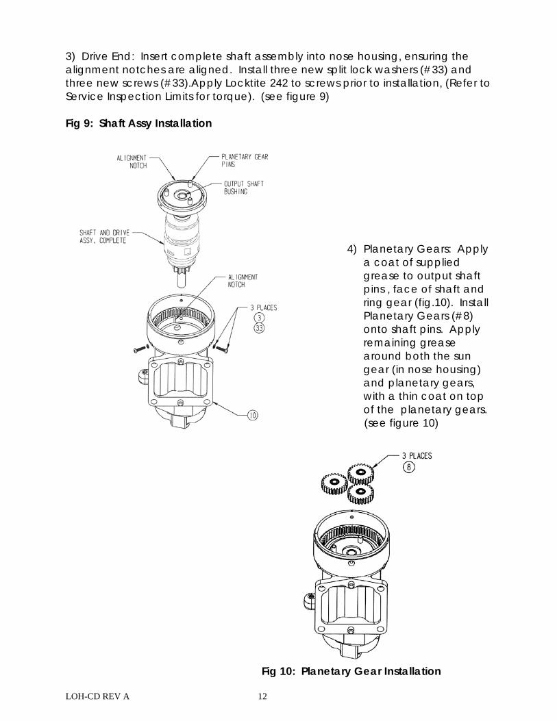
3) Drive End: Insert complete shaft assembly into nose housing, ensuring the alignment notches are aligned. Install three new split lock washers (#33) and three new screws (#33).Apply Locktite 242 to screws prior to installation, (Refer to Service Inspection Limits for torque). (see figure 9) Fig 9: Shaft Assy Installation
4) Planetary Gears: Apply
a coat of supplied grease to output shaft pins , face of shaft and ring gear (fig.10). Install Planetary Gears (#8) onto shaft pins. Apply remaining grease around both the sun gear (in nose housing) and planetary gears, with a thin coat on top of the planetary gears.
(see figure 10)
Fig 10: Planetary Gear Installation

LOH-CD REV A 13
5) Anchor Ring: Install Grease Shield (#14) with raised center ridge facing away from planetary gears, Wave Washer (#30) and Threaded Anchor Ring (#14). Attach Anchor Ring to Nose Housing with four new screws (#14) using Loctite 242, (Refer to Service Inspection Limits for torque). (see figure 11)
6) Positive Brush replacement: Install
new Brushes (#23). Ensure that the oval steel washer goes on the stud first then nylon shoulder washer next. Insert the brush assembly (#23) from the inside of the motor case with the nylon shoulder washer inserted into
Fig 11: Anchor ring Installation the stud hole with the long brush lead to the right looking down on the assembly. Next install the black insulating washer followed by the flat washer (#26) then lock washer (#25) then nut (#34) torque to spec and then temporarily install second lock washer (#25) and nut (#34) on the outside of the motor case. (Refer to Service Inspection Limits for torque). (see figure 12)
Fig 12: Positive Brush Installation
Fig 12: Positive Brush Installation
LOH-CD REV A 14
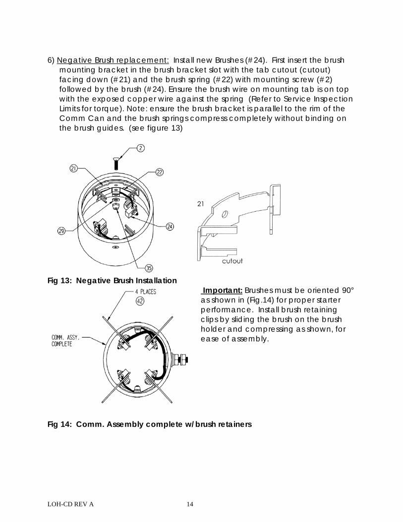
6) Negative Brush replacement: Install new Brushes (#24). First insert the brush
mounting bracket in the brush bracket slot with the tab cutout (cutout) facing down (#21) and the brush spring (#22) with mounting screw (#2) followed by the brush (#24). Ensure the brush wire on mounting tab is on top with the exposed copper wire against the spring (Refer to Service Inspection Limits for torque). Note: ensure the brush bracket is parallel to the rim of the Comm Can and the brush springs compress completely without binding on the brush guides. (see figure 13)
Fig 13: Negative Brush Installation
Important: Brushes must be oriented 90° as shown in (Fig.14) for proper starter performance. Install brush retaining clips by sliding the brush on the brush holder and compressing as shown, for ease of assembly.
Fig 14: Comm. Assembly complete w/brush retainers
LOH-CD REV A 15
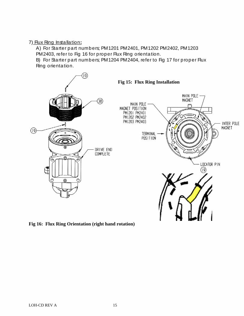
7) Flux Ring Installation:
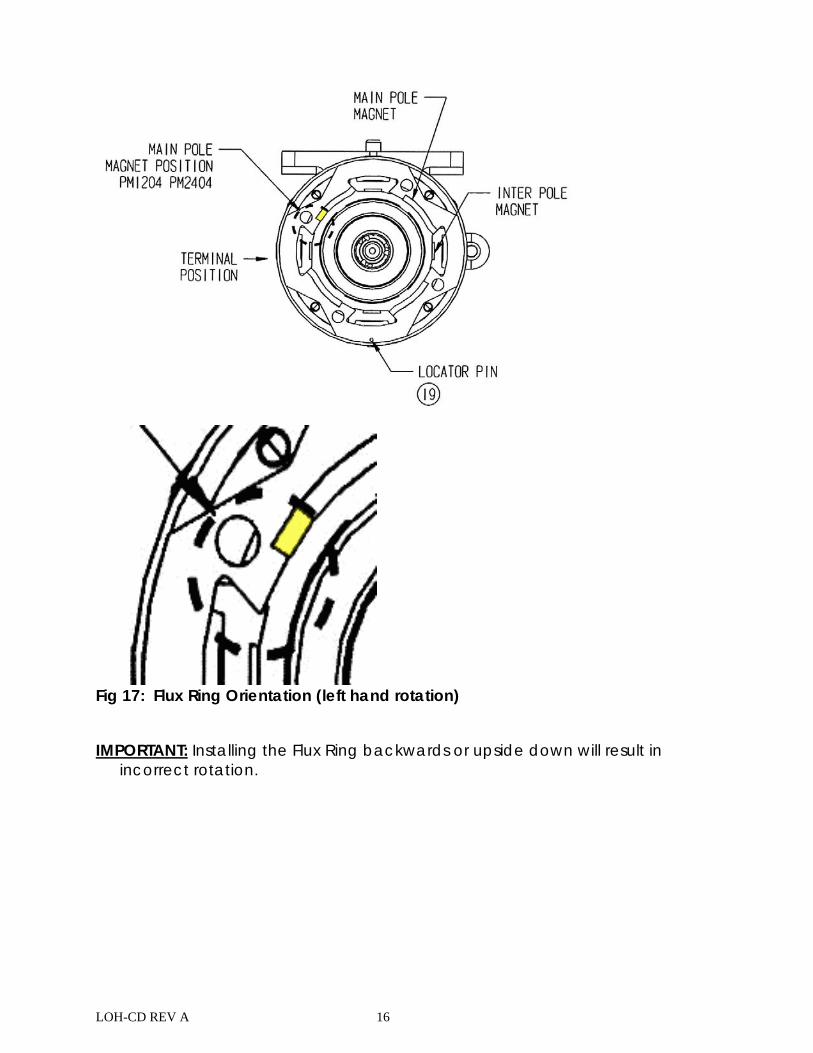
A) For Starter part numbers; PM1201 PM2401, PM1202 PM2402, PM1203 PM2403, refer to Fig 16 for proper Flux Ring orientation. B) For Starter part numbers; PM1204 PM2404, refer to Fig 17 for proper Flux Ring orientation.
Fig 15: Flux Ring Installation
Fig 16: Flux Ring Orientation (right hand rotation)
LOH-CD REV A 16
Fig 17: Flux Ring Orientation (left hand rotation)
IMPORTANT: Installing the Flux Ring backwards or upside down will result in
incorrect rotation.
LOH-CD REV A 17
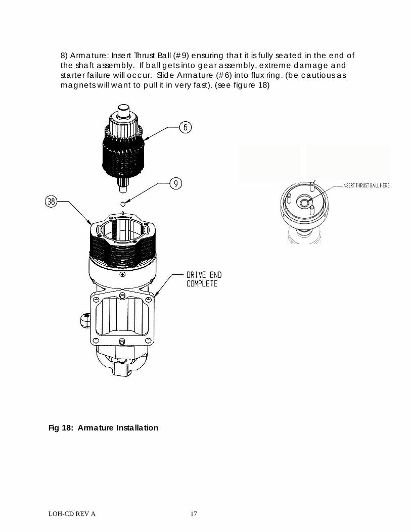
8) Armature: Insert Thrust Ball (#9) ensuring that it is fully seated in the end of the shaft assembly. If ball gets into gear assembly, extreme damage and starter failure will occur. Slide Armature (#6) into flux ring. (be cautious as magnets will want to pull it in very fast). (see figure 18)
Fig 18: Armature Installation
LOH-CD REV A 18
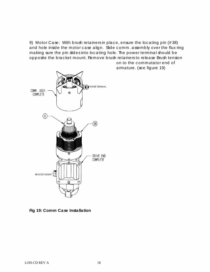
9) Motor Case: With brush retainers in place, ensure the locating pin (#38) and hole inside the motor case align. Slide comm. assembly over the flux ring making sure the pin slides into locating hole. The power terminal should be opposite the bracket mount. Remove brush retainers to release Brush tension
on to the commutator end of armature. (see figure 19)
Fig 19: Comm Case Installation
LOH-CD REV A 19
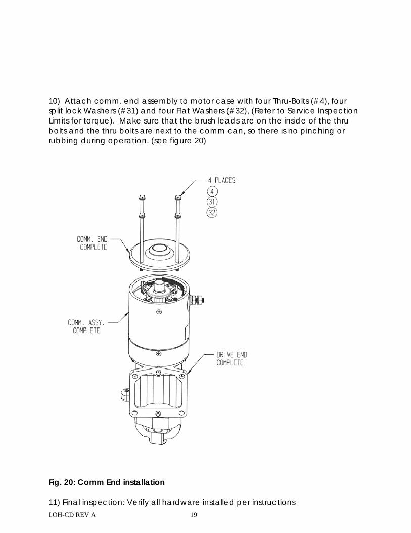
10) Attach comm. end assembly to motor case with four Thru-Bolts (#4), four split lock Washers (#31) and four Flat Washers (#32), (Refer to Service Inspection Limits for torque). Make sure that the brush leads are on the inside of the thru bolts and the thru bolts are next to the comm can, so there is no pinching or rubbing during operation. (see figure 20)
Fig. 20: Comm End installation 11) Final inspection: Verify all hardware installed per instructions
LOH-CD REV A 20
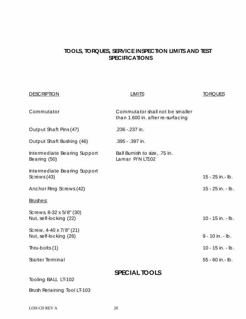
TOOLS, TORQUES, SERVICE INSPECTION LIMITS AND TEST
SPECIFICATIONS DESCRIPTION LIMITS TORQUES
Commutator Commutator shall not be smaller than 1.600 in. after re-surfacing
Output Shaft Pins (47) .236 -.237 in. Output Shaft Bushing (46) .395 - .397 in. Intermediate Bearing Support Ball Burnish to size, .75 in. Bearing (50) Lamar P/N LT102 Intermediate Bearing Support Screws (43) 15 - 25 in.- lb. Anchor Ring Screws (42) 15 - 25 in. - lb.
Brushes: Screws, 8-32 x 5/8" (30) Nut, self-locking (22) 10 - 15 in. - lb. Screw, 4-40 x 7/8" (21) Nut, self-locking (26) 9 - 10 in. - lb. Thru-bolts (1) 10 - 15 in. - lb. Starter Terminal 55 - 60 in.- lb.
SPECIAL TOOLS Tooling BALL LT-102
Brush Retaining Tool LT-103
LOH-CD REV A 21
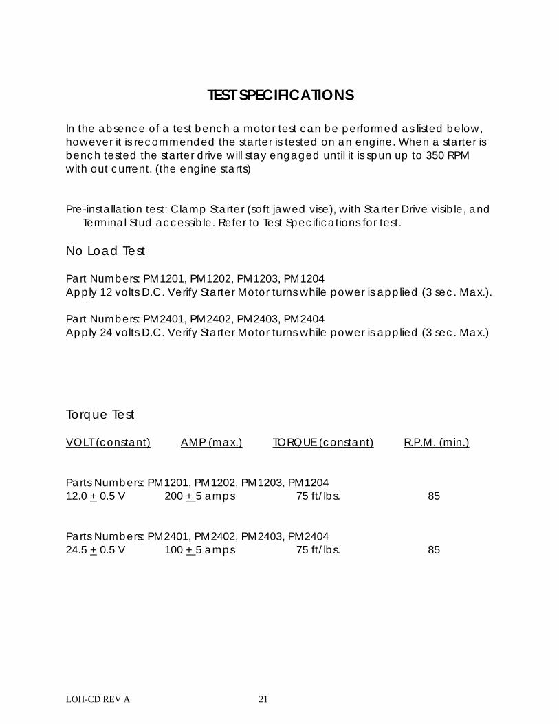
TEST SPECIFICATIONS
In the absence of a test bench a motor test can be performed as listed below, however it is recommended the starter is tested on an engine. When a starter is bench tested the starter drive will stay engaged until it is spun up to 350 RPM with out current. (the engine starts) Pre-installation test: Clamp Starter (soft jawed vise), with Starter Drive visible, and
Terminal Stud accessible. Refer to Test Specifications for test. No Load Test Part Numbers: PM1201, PM1202, PM1203, PM1204 Apply 12 volts D.C. Verify Starter Motor turns while power is applied (3 sec. Max.). Part Numbers: PM2401, PM2402, PM2403, PM2404 Apply 24 volts D.C. Verify Starter Motor turns while power is applied (3 sec. Max.) Torque Test VOLT (constant) AMP (max.) TORQUE (constant) R.P.M. (min.) Parts Numbers: PM1201, PM1202, PM1203, PM1204 12.0 + 0.5 V 200 + 5 amps 75 ft/lbs. 85 Parts Numbers: PM2401, PM2402, PM2403, PM2404 24.5 + 0.5 V 100 + 5 amps 75 ft/lbs. 85
LOH-CD REV A 22
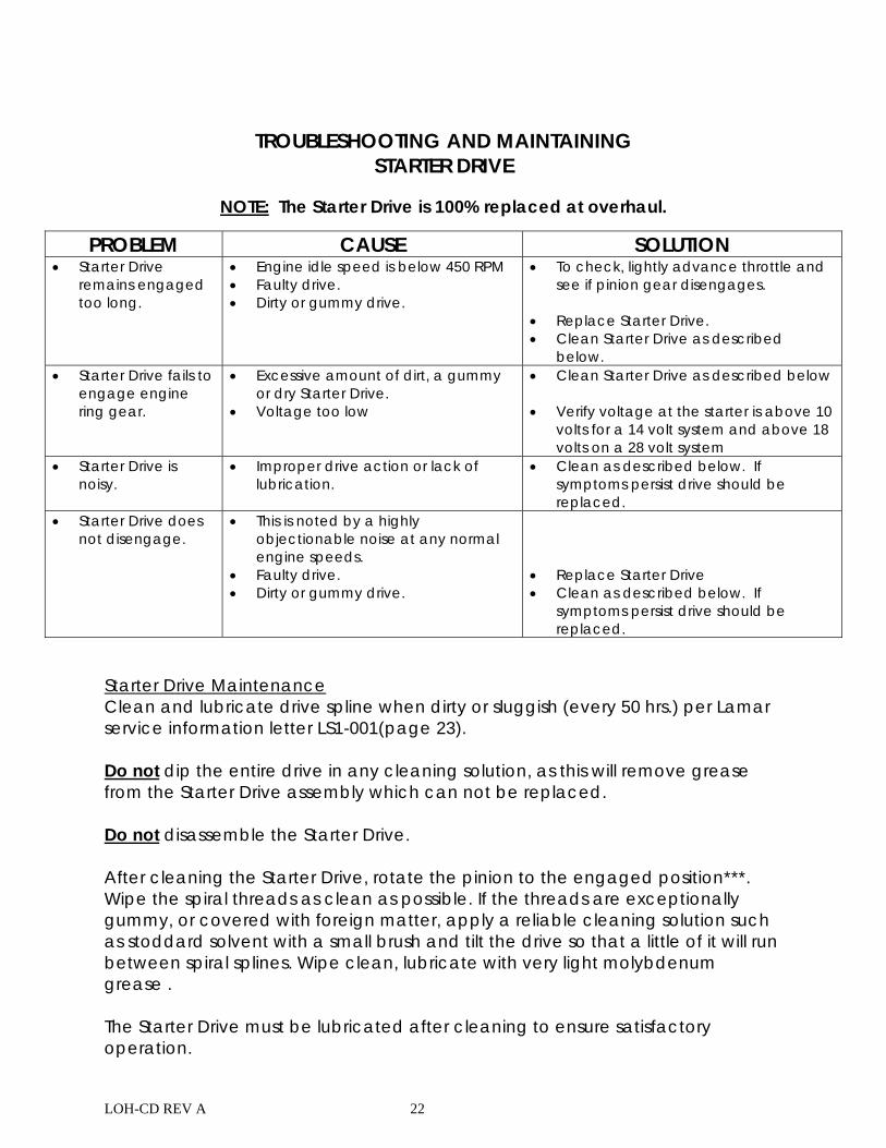
TROUBLESHOOTING AND MAINTAINING STARTER DRIVE
NOTE: The Starter Drive is 100% replaced at overhaul.
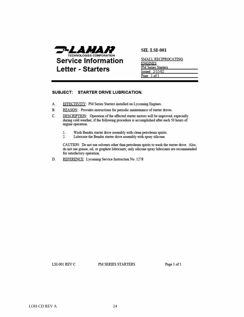
Starter Drive Maintenance Clean and lubricate drive spline when dirty or sluggish (every 50 hrs.) per Lamar service information letter LS1-001(page 23). Do not dip the entire drive in any cleaning solution, as this will remove grease from the Starter Drive assembly which can not be replaced. Do not disassemble the Starter Drive. After cleaning the Starter Drive, rotate the pinion to the engaged position***. Wipe the spiral threads as clean as possible. If the threads are exceptionally gummy, or covered with foreign matter, apply a reliable cleaning solution such as stoddard solvent with a small brush and tilt the drive so that a little of it will run between spiral splines. Wipe clean, lubricate with very light molybdenum grease . The Starter Drive must be lubricated after cleaning to ensure satisfactory operation.
PROBLEM CAUSE SOLUTION Starter Drive
remains engaged too long.
Engine idle speed is below 450 RPM Faulty drive. Dirty or gummy drive.
To check, lightly advance throttle and see if pinion gear disengages.
Replace Starter Drive. Clean Starter Drive as described
below. Starter Drive fails to
engage engine ring gear.
Excessive amount of dirt, a gummy or dry Starter Drive.
Voltage too low
Clean Starter Drive as described below Verify voltage at the starter is above 10
volts for a 14 volt system and above 18 volts on a 28 volt system
Starter Drive is noisy.
Improper drive action or lack of lubrication.
Clean as described below. If symptoms persist drive should be replaced.
Starter Drive does not disengage.
This is noted by a highly objectionable noise at any normal engine speeds.
Faulty drive. Dirty or gummy drive.
Replace Starter Drive Clean as described below. If
symptoms persist drive should be replaced.
LOH-CD REV A 23
*** note starter drive will not retract until it is placed on the engine and the engine is started.
LOH-CD REV A 24
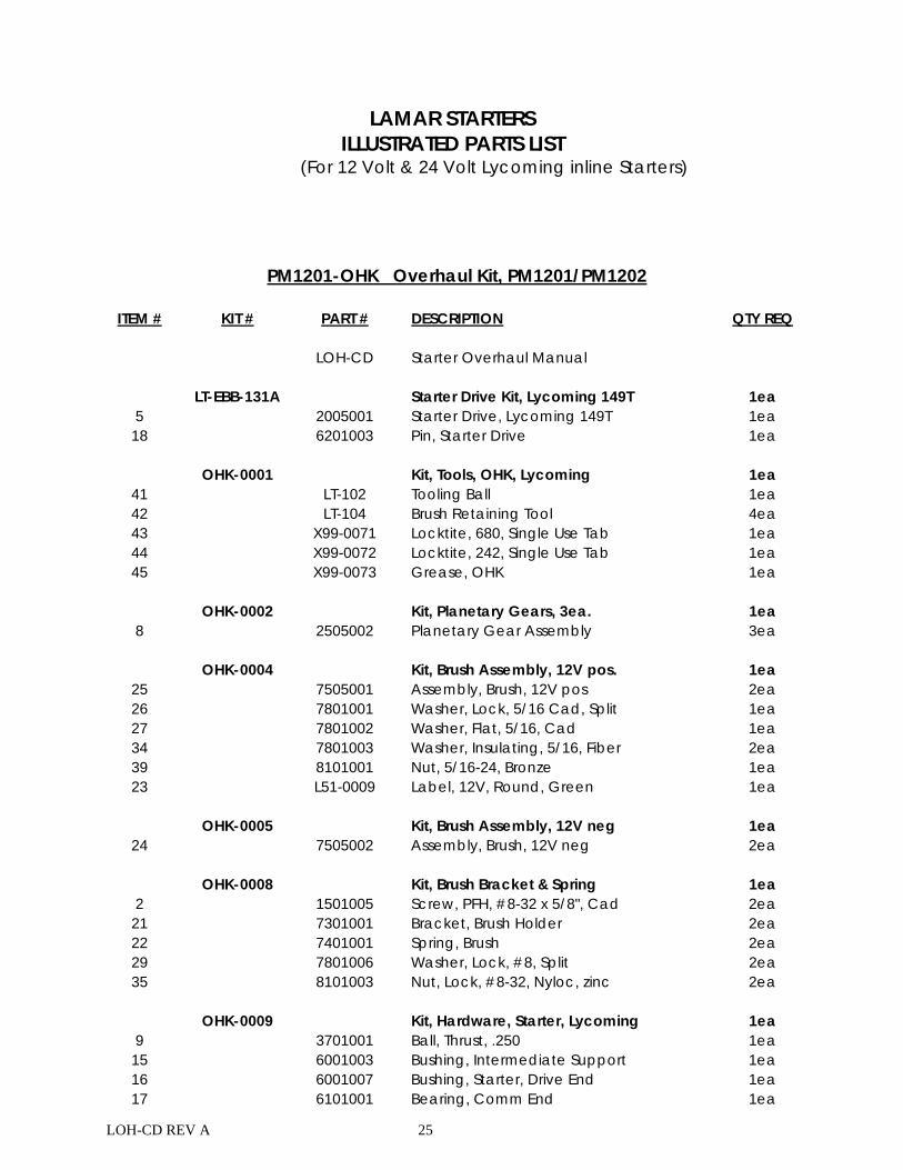
LOH-CD REV A 25
LAMAR STARTERS
ILLUSTRATED PARTS LIST (For 12 Volt & 24 Volt Lycoming inline Starters)
PM1201-OHK Overhaul Kit, PM1201/PM1202
ITEM # KIT # PART # DESCRIPTION QTY REQ LOH-CD Starter Overhaul Manual LT-EBB-131A Starter Drive Kit, Lycoming 149T 1ea
5 2005001 Starter Drive, Lycoming 149T 1ea 18 6201003 Pin, Starter Drive 1ea
OHK-0001 Kit, Tools, OHK, Lycoming 1ea
41 LT-102 Tooling Ball 1ea 42 LT-104 Brush Retaining Tool 4ea 43 X99-0071 Locktite, 680, Single Use Tab 1ea 44 X99-0072 Locktite, 242, Single Use Tab 1ea 45 X99-0073 Grease, OHK 1ea
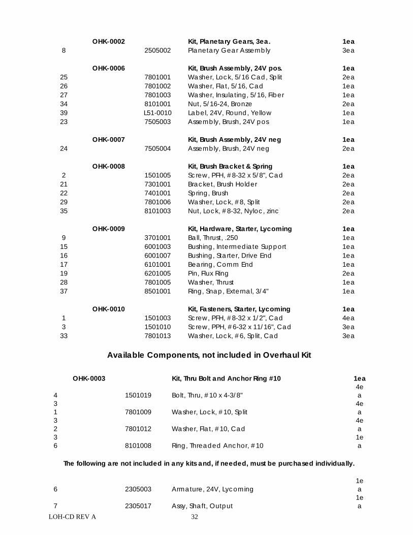
OHK-0002 Kit, Planetary Gears, 3ea. 1ea
8 2505002 Planetary Gear Assembly 3ea OHK-0004 Kit, Brush Assembly, 12V pos. 1ea
25 7505001 Assembly, Brush, 12V pos 2ea 26 7801001 Washer, Lock, 5/16 Cad, Split 1ea 27 7801002 Washer, Flat, 5/16, Cad 1ea 34 7801003 Washer, Insulating, 5/16, Fiber 2ea 39 8101001 Nut, 5/16-24, Bronze 1ea 23 L51-0009 Label, 12V, Round, Green 1ea
OHK-0005 Kit, Brush Assembly, 12V neg 1ea
24 7505002 Assembly, Brush, 12V neg 2ea OHK-0008 Kit, Brush Bracket & Spring 1ea
2 1501005 Screw, PFH, #8-32 x 5/8", Cad 2ea 21 7301001 Bracket, Brush Holder 2ea 22 7401001 Spring, Brush 2ea 29 7801006 Washer, Lock, #8, Split 2ea 35 8101003 Nut, Lock, #8-32, Nyloc, zinc 2ea
OHK-0009 Kit, Hardware, Starter, Lycoming 1ea
9 3701001 Ball, Thrust, .250 1ea 15 6001003 Bushing, Intermediate Support 1ea 16 6001007 Bushing, Starter, Drive End 1ea 17 6101001 Bearing, Comm End 1ea

LOH-CD REV A 26
19 6201005 Pin, Flux Ring 2ea 28 7801005 Washer, Thrust 1ea 37 8501001 Ring, Snap, External, 3/4" 1ea
OHK-0010 Kit, Fasteners, Starter, Lycoming 1ea
1 1501003 Screw, PFH, #8-32 x 1/2", Cad 4ea 3 1501010 Screw, PPH, #6-32 x 11/16", Cad 3ea 33 7801013 Washer, Lock, #6, Split, Cad 3ea
Available Components, not included in Overhaul Kit OHK-0003 Kit, Thru Bolt and Anchor Ring #10 1ea
4 1501019 Bolt, Thru, #10 x 4-3/8" 4ea
31 7801009 Washer, Lock, #10, Split
4ea
32 7801012 Washer, Flat, #10, Cad
4ea
36 8101008 Ring, Threaded Anchor, #10
1ea
The following are not included in any kits and, if needed, must be purchased individually.
6 2305002 Armature, 12V, Lycoming 1ea
7 2305017 Assy, Shaft, Output 1ea
10 5005001 Assy, Starter Nose
1ea
11 5101002 Support, Intermediate, Shaft
1ea
12 5201001 Case, Motor, Lycoming
1ea
13 5301001 Comm end
1ea
14 5401001 Shield, Grease
1ea
20 6301003 Label, Starter Drive Maintenance
1ea
30 7801008 Washer, Wave
1ea
38 9005001 Assy, Flux Ring, Lyc, Complete
1ea
40 L52-0044 Label, Product I.D., 2" x 1"
1ea
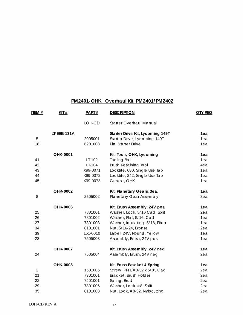
LOH-CD REV A 27
PM2401-OHK Overhaul Kit, PM2401/PM2402
ITEM # KIT # PART # DESCRIPTION QTY REQ
LOH-CD Starter Overhaul Manual LT-EBB-131A Starter Drive Kit, Lycoming 149T 1ea 5 2005001 Starter Drive, Lycoming 149T 1ea
18 6201003 Pin, Starter Drive 1ea OHK-0001 Kit, Tools, OHK, Lycoming 1ea
41 LT-102 Tooling Ball 1ea 42 LT-104 Brush Retaining Tool 4ea 43 X99-0071 Locktite, 680, Single Use Tab 1ea 44 X99-0072 Locktite, 242, Single Use Tab 1ea 45 X99-0073 Grease, OHK 1ea
OHK-0002 Kit, Planetary Gears, 3ea. 1ea 8 2505002 Planetary Gear Assembly 3ea OHK-0006 Kit, Brush Assembly, 24V pos. 1ea
25 7801001 Washer, Lock, 5/16 Cad, Split 2ea 26 7801002 Washer, Flat, 5/16, Cad 1ea 27 7801003 Washer, Insulating, 5/16, Fiber 1ea 34 8101001 Nut, 5/16-24, Bronze 2ea 39 L51-0010 Label, 24V, Round, Yellow 1ea 23 7505003 Assembly, Brush, 24V pos 1ea
OHK-0007 Kit, Brush Assembly, 24V neg 1ea
24 7505004 Assembly, Brush, 24V neg 2ea OHK-0008 Kit, Brush Bracket & Spring 1ea 2 1501005 Screw, PFH, #8-32 x 5/8", Cad 2ea
21 7301001 Bracket, Brush Holder 2ea 22 7401001 Spring, Brush 2ea 29 7801006 Washer, Lock, #8, Split 2ea 35 8101003 Nut, Lock, #8-32, Nyloc, zinc 2ea
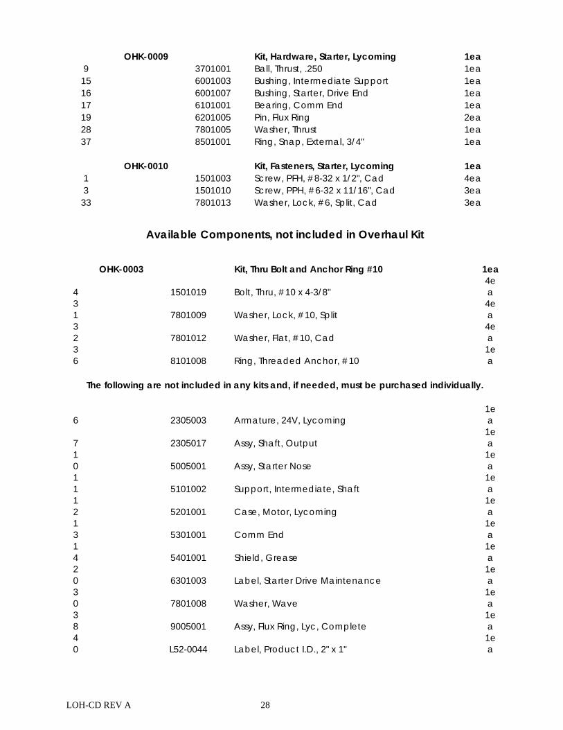
LOH-CD REV A 28
OHK-0009 Kit, Hardware, Starter, Lycoming 1ea 9 3701001 Ball, Thrust, .250 1ea
15 6001003 Bushing, Intermediate Support 1ea 16 6001007 Bushing, Starter, Drive End 1ea 17 6101001 Bearing, Comm End 1ea 19 6201005 Pin, Flux Ring 2ea 28 7801005 Washer, Thrust 1ea 37 8501001 Ring, Snap, External, 3/4" 1ea
OHK-0010 Kit, Fasteners, Starter, Lycoming 1ea 1 1501003 Screw, PFH, #8-32 x 1/2", Cad 4ea 3 1501010 Screw, PPH, #6-32 x 11/16", Cad 3ea
33 7801013 Washer, Lock, #6, Split, Cad 3ea
Available Components, not included in Overhaul Kit OHK-0003 Kit, Thru Bolt and Anchor Ring #10 1ea
4 1501019 Bolt, Thru, #10 x 4-3/8" 4ea
31 7801009 Washer, Lock, #10, Split
4ea
32 7801012 Washer, Flat, #10, Cad
4ea
36 8101008 Ring, Threaded Anchor, #10
1ea
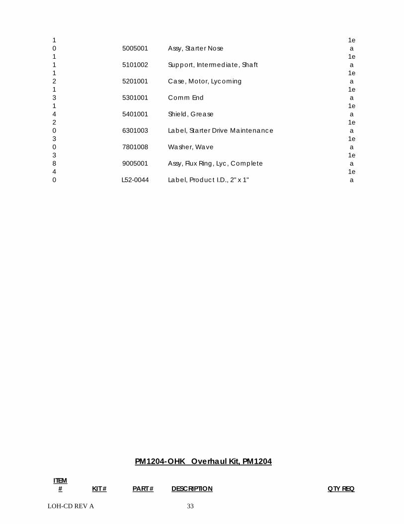
The following are not included in any kits and, if needed, must be purchased individually.
6 2305003 Armature, 24V, Lycoming 1ea
7 2305017 Assy, Shaft, Output 1ea
10 5005001 Assy, Starter Nose
1ea
11 5101002 Support, Intermediate, Shaft
1ea
12 5201001 Case, Motor, Lycoming
1ea
13 5301001 Comm End
1ea
14 5401001 Shield, Grease
1ea
20 6301003 Label, Starter Drive Maintenance
1ea
30 7801008 Washer, Wave
1ea
38 9005001 Assy, Flux Ring, Lyc, Complete
1ea
40 L52-0044 Label, Product I.D., 2" x 1"
1ea
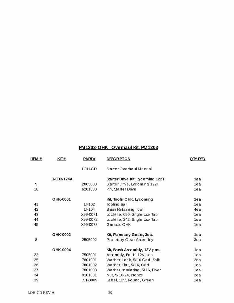
LOH-CD REV A 29
PM1203-OHK Overhaul Kit, PM1203
ITEM # KIT # PART # DESCRIPTION QTY REQ LOH-CD Starter Overhaul Manual LT-EBB-124A Starter Drive Kit, Lycoming 122T 1ea
5 2005003 Starter Drive, Lycoming 122T 1ea 18 6201003 Pin, Starter Drive 1ea
OHK-0001 Kit, Tools, OHK, Lycoming 1ea
41 LT-102 Tooling Ball 1ea 42 LT-104 Brush Retaining Tool 4ea 43 X99-0071 Locktite, 680, Single Use Tab 1ea 44 X99-0072 Locktite, 242, Single Use Tab 1ea 45 X99-0073 Grease, OHK 1ea
OHK-0002 Kit, Planetary Gears, 3ea. 1ea
8 2505002 Planetary Gear Assembly 3ea OHK-0004 Kit, Brush Assembly, 12V pos. 1ea
23 7505001 Assembly, Brush, 12V pos 1ea 25 7801001 Washer, Lock, 5/16 Cad, Split 2ea 26 7801002 Washer, Flat, 5/16, Cad 1ea 27 7801003 Washer, Insulating, 5/16, Fiber 1ea 34 8101001 Nut, 5/16-24, Bronze 2ea 39 L51-0009 Label, 12V, Round, Green 1ea
LOH-CD REV A 30
OHK-0005 Kit, Brush Assembly, 12V neg 1ea 24 7505002 Assembly, Brush, 12V neg 2ea
OHK-0008 Kit, Brush Bracket & Spring 1ea
2 1501005 Screw, PFH, #8-32 x 5/8", Cad 2ea 21 7301001 Bracket, Brush Holder 2ea 22 7401001 Spring, Brush 2ea 29 7801006 Washer, Lock, #8, Split 2ea 35 8101003 Nut, Lock, #8-32, Nyloc, zinc 2ea
OHK-0009 Kit, Hardware, Starter, Lycoming 1ea
9 3701001 Ball, Thrust, .250 1ea 15 6001003 Bushing, Intermediate Support 1ea 16 6001007 Bushing, Starter, Drive End 1ea 17 6101001 Bearing, Comm End 1ea 19 6201005 Pin, Flux Ring 2ea 28 7801005 Washer, Thrust 1ea 37 8501001 Ring, Snap, External, 3/4" 1ea
OHK-0010 Kit, Fasteners, Starter, Lycoming 1ea
1 1501003 Screw, PFH, #8-32 x 1/2", Cad 4ea 3 1501010 Screw, PPH, #6-32 x 11/16", Cad 3ea 33 7801013 Washer, Lock, #6, Split, Cad 3ea
Available Components, not included in Overhaul Kit
OHK-0003 Kit, Thru Bolt and Anchor Ring #10 1ea
4 1501019 Bolt, Thru, #10 x 4-3/8" 4ea
31 7801009 Washer, Lock, #10, Split
4ea
32 7801012 Washer, Flat, #10, Cad
4ea
36 8101008 Ring, Threaded Anchor, #10
1ea
The following are not included in any kits and, if needed, must be purchased individually.
6 2305002 Armature, 12V, Lycoming 1ea
7 2305017 Assy, Shaft, Output 1ea
10 5005001 Assy, Starter Nose
1ea
11 5101002 Support, Intermediate, Shaft
1ea
12 5201001 Case, Motor, Lycoming
1ea
13 5301001 Comm End
1ea
14 5401001 Shield, Grease
1ea
20 6301003 Label, Starter Drive Maintenance
1ea
LOH-CD REV A 31
30 7801008 Washer, Wave
1ea
38 9005001 Assy, Flux Ring, Lyc, Complete
1ea
40 L52-0044 Label, Product I.D., 2" x 1"
1ea
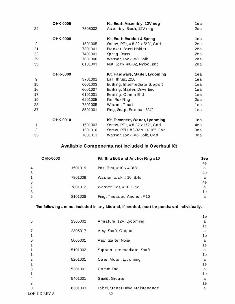
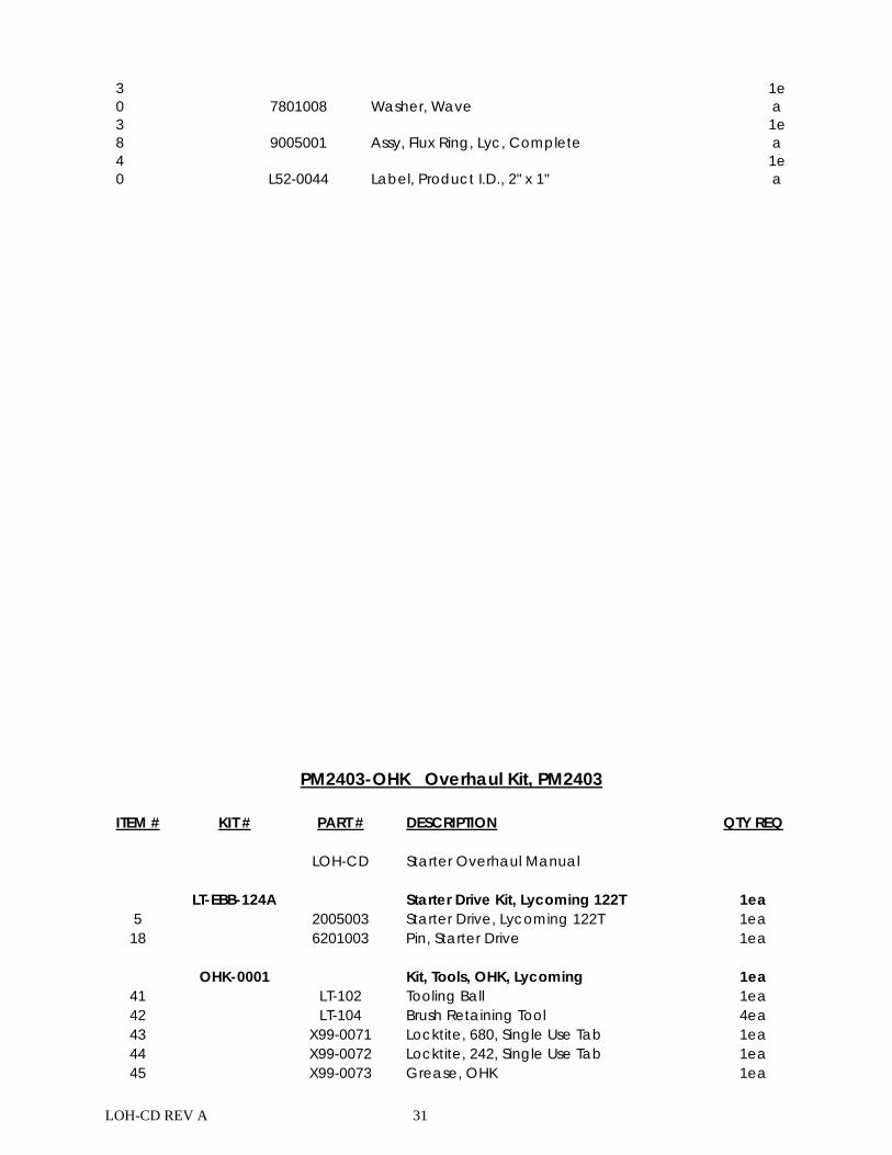
PM2403-OHK Overhaul Kit, PM2403
ITEM # KIT # PART # DESCRIPTION QTY REQ LOH-CD Starter Overhaul Manual LT-EBB-124A Starter Drive Kit, Lycoming 122T 1ea
5 2005003 Starter Drive, Lycoming 122T 1ea 18 6201003 Pin, Starter Drive 1ea
OHK-0001 Kit, Tools, OHK, Lycoming 1ea
41 LT-102 Tooling Ball 1ea 42 LT-104 Brush Retaining Tool 4ea 43 X99-0071 Locktite, 680, Single Use Tab 1ea 44 X99-0072 Locktite, 242, Single Use Tab 1ea 45 X99-0073 Grease, OHK 1ea
LOH-CD REV A 32
OHK-0002 Kit, Planetary Gears, 3ea. 1ea 8 2505002 Planetary Gear Assembly 3ea OHK-0006 Kit, Brush Assembly, 24V pos. 1ea
25 7801001 Washer, Lock, 5/16 Cad, Split 2ea 26 7801002 Washer, Flat, 5/16, Cad 1ea 27 7801003 Washer, Insulating, 5/16, Fiber 1ea 34 8101001 Nut, 5/16-24, Bronze 2ea 39 L51-0010 Label, 24V, Round, Yellow 1ea 23 7505003 Assembly, Brush, 24V pos 1ea
OHK-0007 Kit, Brush Assembly, 24V neg 1ea
24 7505004 Assembly, Brush, 24V neg 2ea OHK-0008 Kit, Brush Bracket & Spring 1ea
2 1501005 Screw, PFH, #8-32 x 5/8", Cad 2ea 21 7301001 Bracket, Brush Holder 2ea 22 7401001 Spring, Brush 2ea 29 7801006 Washer, Lock, #8, Split 2ea 35 8101003 Nut, Lock, #8-32, Nyloc, zinc 2ea
OHK-0009 Kit, Hardware, Starter, Lycoming 1ea
9 3701001 Ball, Thrust, .250 1ea 15 6001003 Bushing, Intermediate Support 1ea 16 6001007 Bushing, Starter, Drive End 1ea 17 6101001 Bearing, Comm End 1ea 19 6201005 Pin, Flux Ring 2ea 28 7801005 Washer, Thrust 1ea 37 8501001 Ring, Snap, External, 3/4" 1ea
OHK-0010 Kit, Fasteners, Starter, Lycoming 1ea
1 1501003 Screw, PFH, #8-32 x 1/2", Cad 4ea 3 1501010 Screw, PPH, #6-32 x 11/16", Cad 3ea 33 7801013 Washer, Lock, #6, Split, Cad 3ea
Available Components, not included in Overhaul Kit
OHK-0003 Kit, Thru Bolt and Anchor Ring #10 1ea
4 1501019 Bolt, Thru, #10 x 4-3/8" 4ea
31 7801009 Washer, Lock, #10, Split
4ea
32 7801012 Washer, Flat, #10, Cad
4ea
36 8101008 Ring, Threaded Anchor, #10
1ea
The following are not included in any kits and, if needed, must be purchased individually.
6 2305003 Armature, 24V, Lycoming 1ea
7 2305017 Assy, Shaft, Output 1ea
LOH-CD REV A 33
10 5005001 Assy, Starter Nose
1ea
11 5101002 Support, Intermediate, Shaft
1ea
12 5201001 Case, Motor, Lycoming
1ea
13 5301001 Comm End
1ea
14 5401001 Shield, Grease
1ea
20 6301003 Label, Starter Drive Maintenance
1ea
30 7801008 Washer, Wave
1ea
38 9005001 Assy, Flux Ring, Lyc, Complete
1ea
40 L52-0044 Label, Product I.D., 2" x 1"
1ea
PM1204-OHK Overhaul Kit, PM1204
ITEM # KIT # PART # DESCRIPTION QTY REQ
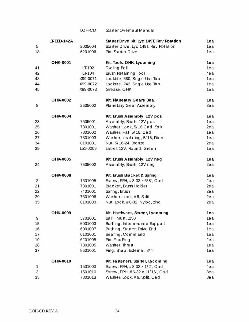
LOH-CD REV A 34
LOH-CD Starter Overhaul Manual LT-EBB-142A Starter Drive Kit, Lyc 149T, Rev Rotation 1ea 5 2005004 Starter Drive, Lyc 149T, Rev Rotation 1ea
18 6201006 Pin, Starter Drive 1ea OHK-0001 Kit, Tools, OHK, Lycoming 1ea
41 LT-102 Tooling Ball 1ea 42 LT-104 Brush Retaining Tool 4ea 43 X99-0071 Locktite, 680, Single Use Tab 1ea 44 X99-0072 Locktite, 242, Single Use Tab 1ea 45 X99-0073 Grease, OHK 1ea
OHK-0002 Kit, Planetary Gears, 3ea. 1ea 8 2505002 Planetary Gear Assembly 3ea OHK-0004 Kit, Brush Assembly, 12V pos. 1ea
23 7505001 Assembly, Brush, 12V pos 1ea 25 7801001 Washer, Lock, 5/16 Cad, Split 2ea 26 7801002 Washer, Flat, 5/16, Cad 1ea 27 7801003 Washer, Insulating, 5/16, Fiber 1ea 34 8101001 Nut, 5/16-24, Bronze 2ea 39 L51-0009 Label, 12V, Round, Green 1ea
OHK-0005 Kit, Brush Assembly, 12V neg 1ea
24 7505002 Assembly, Brush, 12V neg 2ea OHK-0008 Kit, Brush Bracket & Spring 1ea 2 1501005 Screw, PFH, #8-32 x 5/8", Cad 2ea
21 7301001 Bracket, Brush Holder 2ea 22 7401001 Spring, Brush 2ea 29 7801006 Washer, Lock, #8, Split 2ea 35 8101003 Nut, Lock, #8-32, Nyloc, zinc 2ea
OHK-0009 Kit, Hardware, Starter, Lycoming 1ea 9 3701001 Ball, Thrust, .250 1ea
15 6001003 Bushing, Intermediate Support 1ea 16 6001007 Bushing, Starter, Drive End 1ea 17 6101001 Bearing, Comm End 1ea 19 6201005 Pin, Flux Ring 2ea 28 7801005 Washer, Thrust 1ea 37 8501001 Ring, Snap, External, 3/4" 1ea
OHK-0010 Kit, Fasteners, Starter, Lycoming 1ea 1 1501003 Screw, PFH, #8-32 x 1/2", Cad 4ea 3 1501010 Screw, PPH, #6-32 x 11/16", Cad 3ea
33 7801013 Washer, Lock, #6, Split, Cad 3ea
LOH-CD REV A 35
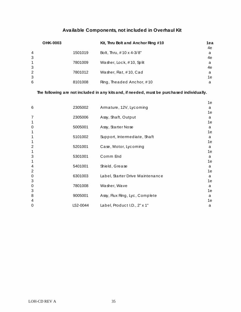
Available Components, not included in Overhaul Kit
OHK-0003 Kit, Thru Bolt and Anchor Ring #10 1ea
4 1501019 Bolt, Thru, #10 x 4-3/8" 4ea
31 7801009 Washer, Lock, #10, Split
4ea
32 7801012 Washer, Flat, #10, Cad
4ea
36 8101008 Ring, Theaded Anchor, #10
1ea
The following are not included in any kits and, if needed, must be purchased individually.
6 2305002 Armature, 12V, Lycoming 1ea
7 2305006 Assy, Shaft, Output 1ea
10 5005001 Assy, Starter Nose
1ea
11 5101002 Support, Intermediate, Shaft
1ea
12 5201001 Case, Motor, Lycoming
1ea
13 5301001 Comm End
1ea
14 5401001 Shield, Grease
1ea
20 6301003 Label, Starter Drive Maintenance
1ea
30 7801008 Washer, Wave
1ea
38 9005001 Assy, Flux Ring, Lyc, Complete
1ea
40 L52-0044 Label, Product I.D., 2" x 1"
1ea
LOH-CD REV A 36
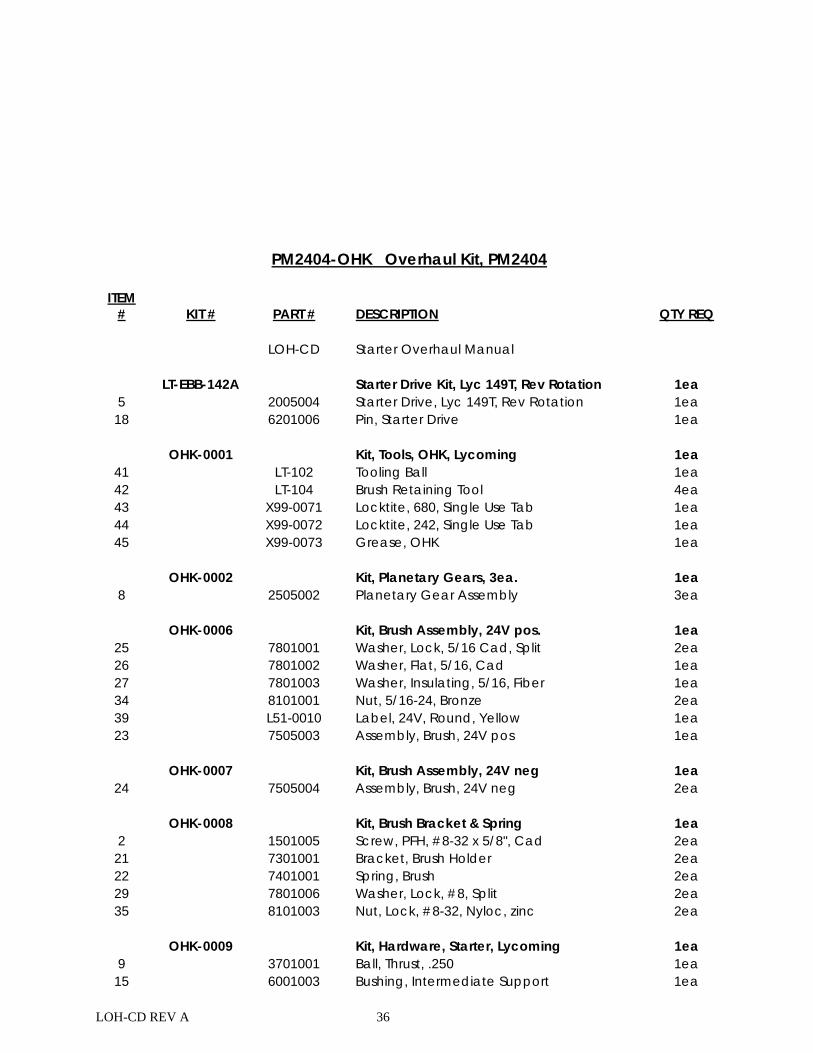
PM2404-OHK Overhaul Kit, PM2404
ITEM # KIT # PART # DESCRIPTION QTY REQ LOH-CD Starter Overhaul Manual LT-EBB-142A Starter Drive Kit, Lyc 149T, Rev Rotation 1ea 5 2005004 Starter Drive, Lyc 149T, Rev Rotation 1ea
18 6201006 Pin, Starter Drive 1ea OHK-0001 Kit, Tools, OHK, Lycoming 1ea
41 LT-102 Tooling Ball 1ea 42 LT-104 Brush Retaining Tool 4ea 43 X99-0071 Locktite, 680, Single Use Tab 1ea 44 X99-0072 Locktite, 242, Single Use Tab 1ea 45 X99-0073 Grease, OHK 1ea
OHK-0002 Kit, Planetary Gears, 3ea. 1ea 8 2505002 Planetary Gear Assembly 3ea OHK-0006 Kit, Brush Assembly, 24V pos. 1ea
25 7801001 Washer, Lock, 5/16 Cad, Split 2ea 26 7801002 Washer, Flat, 5/16, Cad 1ea 27 7801003 Washer, Insulating, 5/16, Fiber 1ea 34 8101001 Nut, 5/16-24, Bronze 2ea 39 L51-0010 Label, 24V, Round, Yellow 1ea 23 7505003 Assembly, Brush, 24V pos 1ea
OHK-0007 Kit, Brush Assembly, 24V neg 1ea
24 7505004 Assembly, Brush, 24V neg 2ea OHK-0008 Kit, Brush Bracket & Spring 1ea 2 1501005 Screw, PFH, #8-32 x 5/8", Cad 2ea
21 7301001 Bracket, Brush Holder 2ea 22 7401001 Spring, Brush 2ea 29 7801006 Washer, Lock, #8, Split 2ea 35 8101003 Nut, Lock, #8-32, Nyloc, zinc 2ea
OHK-0009 Kit, Hardware, Starter, Lycoming 1ea 9 3701001 Ball, Thrust, .250 1ea
15 6001003 Bushing, Intermediate Support 1ea
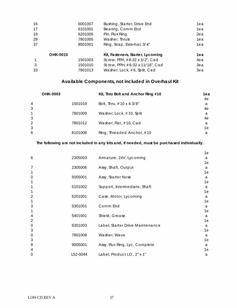
LOH-CD REV A 37
16 6001007 Bushing, Starter, Drive End 1ea 17 6101001 Bearing, Comm End 1ea 19 6201005 Pin, Flux Ring 2ea 28 7801005 Washer, Thrust 1ea 37 8501001 Ring, Snap, External, 3/4" 1ea
OHK-0010 Kit, Fasteners, Starter, Lycoming 1ea 1 1501003 Screw, PFH, #8-32 x 1/2", Cad 4ea 3 1501010 Screw, PPH, #6-32 x 11/16", Cad 3ea
33 7801013 Washer, Lock, #6, Split, Cad 3ea
Available Components, not included in Overhaul Kit OHK-0003 Kit, Thru Bolt and Anchor Ring #10 1ea
4 1501019 Bolt, Thru, #10 x 4-3/8" 4ea
31 7801009 Washer, Lock, #10, Split
4ea
32 7801012 Washer, Flat, #10, Cad
4ea
36 8101008 Ring, Threaded Anchor, #10
1ea
The following are not included in any kits and, if needed, must be purchased individually.
6 2305003 Armature, 24V, Lycoming 1ea
7 2305006 Assy, Shaft, Output 1ea
10 5005001 Assy, Starter Nose
1ea
11 5101002 Support, Intermediate, Shaft
1ea
12 5201001 Case, Motor, Lycoming
1ea
13 5301001 Comm End
1ea
14 5401001 Shield, Grease
1ea
20 6301003 Label, Starter Drive Maintenance
1ea
30 7801008 Washer, Wave
1ea
38 9005001 Assy, Flux Ring, Lyc, Complete
1ea
40 L52-0044 Label, Product I.D., 2" x 1"
1ea
LOH-CD REV A 38
Support
For technical support contact Lamar Technologies LLC at: [email protected] 360-651-6666 Lamar Technologies LLC 14900 40th Ave. NE Marysville, Washington 98271