Embed Size (px)
Citation preview
Lake Way Project Demonstration PlantSalt Lake Potash Pty Ltd
EPA Referral
Supporting Information
Revision No 1
March 2019
Salt Lake Potash Pty Ltd
Lake Way SOP Demonstration Plant
EPA Referral
Supporting Information
Revision No 1
March 2019
Salt Lake Potash - Lake Way Project Demonstration Plant
Supporting Document to EPA Referral
Revision No: 1 Date: March 2019
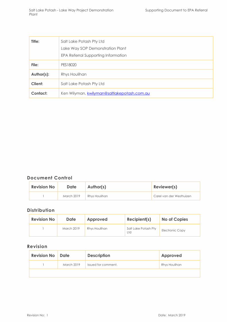
Title: Salt Lake Potash Pty Ltd
Lake Way SOP Demonstration Plant
EPA Referral Supporting Information
File: PES18020
Author(s): Rhys Houlihan
Client: Salt Lake Potash Pty Ltd
Contact: Ken Wilyman, [email protected]
Document Control
Revision No Date Author(s) Reviewer(s)
1 March 2019 Rhys Houlihan Carel van der Westhuizen
Distribution
Revision No Date Approved Recipient(s) No of Copies
1 March 2019 Rhys Houlihan Salt Lake Potash Pty Ltd Electronic Copy
Revision
Revision No Date Description Approved
1 March 2019 Issued for comment. Rhys Houlihan
Salt Lake Potash - Lake Way Project Demonstration Plant
Supporting Document to EPA Referral
Revision No: 1 Date: March 2019
Executive Summary
The Lake Way SOP Demonstration Plant (the Project) is a semi-brownfield project to abstract and treat brine resources from the Lake Way playa to produce a Sulphate of Potash (SOP) product for use as a fertiliser. Brine harvesting and processing activities will be co-located with Blackham Resources existing Matilda Gold mining operation, to minimise the Project disturbance footprint and to take advantage of synergies in the use of support infrastructure. The manager and proponent of the Project is Salt Lake Potash Limited (SO4). SO4 is incorporated in Australia and has shares listed on the ASX (SO4).
The Project occupies salt lake terrain in the northeast part of the Yilgarn Craton of Western Australia. Exploration into potential potash resources at Lake Way commenced in 2016 and has continued through to present. Pit sampling, auger and air-core drilling has demonstrated the presence of consistent high-grade potash brine concentrations to significant depths on the salt lake. A Scoping Study was completed in July 2018 and further feasibility study investigations are ongoing.
SO4 aims to confirm confidence in the commercial viability and sustainable quality of its Lake Way potash resource by implementing a field scale demonstration project. The project would establish brine harvesting and treatment facilities sufficient to feed a small commercial scale plant capable of a nominal production rate of 50,000 tonnes of SOP per year. Infrastructure associated with the proposal includes:
On-playa infrastructure: being brine extraction trenches, pond infrastructure and associated pipework.
Off-playa infrastructure: being processing plant, process water pipework and associated infrastructure.
Previous studies completed by others in the Lake Way area and baselineenvironmental studies completed by the proponent have given SO4 a well-developed understanding of the Lake Way area, the surrounding environmental values and potential impacts. These potential impacts and ways to manage and/or mitigate against them are presented in this referral document.
Project implementation is unlikely to result in any adverse environmental impact.
The potential environmental impacts of the project can be managed effectively underregulatory frameworks available under Part V of the Environmental Protection Act 1986, the Mining Act 1978 and the Rights in Water and Irrigation Act 1914.
Salt Lake Potash - Lake Way Project Demonstration Plant
Supporting Document to EPA Referral
Revision No: 1 Page 1 of 94 Date: March 2019
TABLE OF CONTENTS
Abbreviations & Acronyms ............................................................................................................. 5
1 Introduction........................................................................................................................................ 7
1.1 Background ............................................................................................................................. 7
1.2 Purpose of this document ..................................................................................................... 7
1.3 Proponent Details ................................................................................................................... 8
2 Proposal Overview..........................................................................................................................10
2.1 Key Project Objectives.........................................................................................................11
2.2 Proposal Location and Tenure ...........................................................................................11
2.3 Key Proposal Characteristics ..............................................................................................13
2.4 Hydrogeology and Resource Estimate.............................................................................16
2.5 Brine Extraction......................................................................................................................17
2.6 Evaporation Ponds ...............................................................................................................18
2.7 Processing...............................................................................................................................24
2.8 Process water supply............................................................................................................29
2.9 Major Infrastructure ..............................................................................................................29
3 Project justification and Alternatives...........................................................................................31
4 Stakeholder engagement.............................................................................................................32
4.1 Key Stakeholders...................................................................................................................32
4.2 Stakeholder Engagement Process ....................................................................................33
5 Environmental Impact Assessment and Permitting..................................................................35
5.1 Impact Assessment...............................................................................................................35
5.2 EPA Principles.........................................................................................................................36
5.3 Regulatory framework .........................................................................................................38
6 Existing Environment .......................................................................................................................39
6.1 Local and Regional Context ..............................................................................................39
6.2 Social Surroundings...............................................................................................................39
6.3 Climate ...................................................................................................................................40
6.4 Hydrology ...............................................................................................................................41
Salt Lake Potash - Lake Way Project Demonstration Plant
Supporting Document to EPA Referral
Revision No: 1 Page 2 of 94 Date: March 2019
6.5 Lakebed Geology ................................................................................................................43
6.6 Regional Environment..........................................................................................................44
6.7 Remnant Vegetation ...........................................................................................................47
6.8 Groundwater .........................................................................................................................49
6.8.1 Lakebed Sediments........................................................................................................49
6.8.2 On-playa pondage........................................................................................................49
6.8.3 Conceptual Hydrological Model.................................................................................49
6.8.4 Brine Chemistry................................................................................................................52
6.9 Soil and Landscape Systems ..............................................................................................53
7 Identification and Assessment of Environmental Factors .......................................................56
7.1 Identification of factors .......................................................................................................56
7.2 Preliminary Assessment of Environmental Factors ..........................................................62
7.2.1 Flora and Vegetation.....................................................................................................62
7.2.2 Landforms.........................................................................................................................68
7.2.3 Terrestrial Environmental Quality..................................................................................69
7.2.4 Terrestrial Fauna ..............................................................................................................70
7.2.5 Hydrological Processes ..................................................................................................73
7.2.6 Inland Waters Environmental Quality..........................................................................77
7.2.7 Air Quality .........................................................................................................................80
7.2.8 Social Surroundings.........................................................................................................81
7.2.9 Human Health..................................................................................................................84
8 Matters of National Environmental Significance ......................................................................85
8.1 Assessment of MNES Factors...............................................................................................88
8.2 Nuclear Actions.....................................................................................................................88
8.2.1 Activity level.....................................................................................................................89
8.2.2 Assessment .......................................................................................................................89
9 Cumulative Impact Assessment...................................................................................................90
10 Conclusion........................................................................................................................................91
11 References .......................................................................................................................................92
Salt Lake Potash - Lake Way Project Demonstration Plant
Supporting Document to EPA Referral
Revision No: 1 Page 3 of 94 Date: March 2019
List of Tables
Table 2-1: Project Tenure..........................................................................................................................12
Table 2-2: Key proposal characteristics.................................................................................................14
Table 2-3: Land disturbance...................................................................................................................16
Table 2-4 : Mineral Resource Calculation (Sediment Hosted Brine Indicated Resource)...........17
Table 2-5: Harvest Cycle Methodology................................................................................................20
Table 2-6 : Design Basis .............................................................................................................................26
Table 4-1: Key Stakeholders for the Lake Wells Project ......................................................................32
Table 5-1: Principles of environmental management (Lake Way SOP Demonstration Plant)....36
Table 5-2 List of Regulatory Approvals Required for the Project .....................................................38
Table 6-1: Pre-European Vegetation Associations within the Project Development Envelope.47
Table 6-2 : Brine QA/QC Results Summary............................................................................................52
Table 6-3: Soil Landscape Systems within the Lake Way SOP Demonstration Plant Project.......54
Table 7-1: Environmental Factors for the Lake Way SOP Demonstration Plant Project ...............56
Table 7-2 : Summary of Assessment of Environmental Factors for the Lake Way Demonstration Plant Project................................................................................................................................................58
Table 8-1: MNES – applicability to Lake Way SOP Demonstration Plant Project ...........................85
Table 8-2: Significant impact criteria .....................................................................................................86
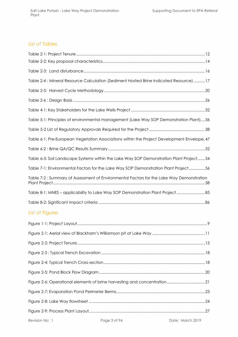
List of Figures
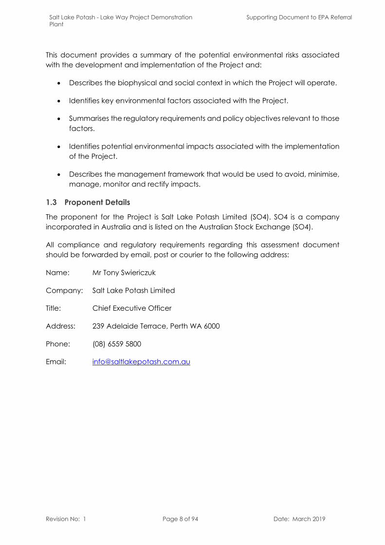
Figure 1-1: Project Layout...........................................................................................................................9
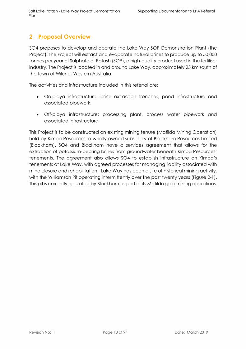
Figure 2-1: Aerial view of Blackham’s Williamson pit at Lake Way ..................................................11
Figure 2-2: Project Tenure.........................................................................................................................15
Figure 2-3 : Typical Trench Excavation ..................................................................................................18
Figure 2-4: Typical Trench Cross-section................................................................................................18
Figure 2-5: Pond Block Flow Diagram ....................................................................................................20
Figure 2-6: Operational elements of brine harvesting and concentration ....................................21
Figure 2-7: Evaporation Pond Perimeter Berms....................................................................................23
Figure 2-8: Lake Way flowsheet ..............................................................................................................24
Figure 2-9: Process Plant Layout..............................................................................................................27
Salt Lake Potash - Lake Way Project Demonstration Plant
Supporting Document to EPA Referral
Revision No: 1 Page 4 of 94 Date: March 2019
Figure 2-10: Process Water Supply Location.........................................................................................30
Figure 5-1: Framework for Environmental Assessments in Western Australia.................................35
Figure 6-1 : Monthly Average Evaporation and Rainfall Comparison, Laverton ..........................40
Figure 6-2 : Monthly Rainfall and Relative Humidity, Wiluna Township............................................41
Figure 6-3 : Monthly Mean Temperature, Wiluna Township...............................................................41
Figure 6-4 : Lake Way Surface Catchment Area (Knight Piezold, 2019).........................................42
Figure 6-5 : Lake Morphology, From Geoscience Australia, (2013), Originally Developed by Bowler (1986) ..............................................................................................................................................43
Figure 6-6 : Map of IBRA bioregions in relation to the Project...........................................................46
Figure 6-7 : Pre-European Vegetation ...................................................................................................48
Figure 6-8 : Depth to Base of Lakebed Sediments, Lake Way..........................................................51
Figure 6-9 : Conceptual Hydrogeological Model ...............................................................................52
Figure 6-10 : Distribution of Potassium in 2018 Test Pit Samples.........................................................53
Figure 6-11 : Distribution of Magnesium in 2018 Test Pit Samples......................................................53
Figure 6-12 : Soil Landscape Systems.....................................................................................................55
Figure 7-1 : Vegetation Condition associated with the Proposal ....................................................65
Figure 7-2 : Groundwater Drawdown with respect to vegetation ..................................................66
Figure 7-3 : Hydrological processes 1% AEP..........................................................................................67
Figure 7-4 : Fauna Habitats ......................................................................................................................72
Figure 7-5 : Water Observations From Space Mapping.....................................................................76
Figure 7-6 : Heritage Sites .........................................................................................................................83
Salt Lake Potash - Lake Way Project Demonstration Plant
Supporting Document to EPA Referral
Revision No: 1 Page 5 of 94 Date: March 2019
Abbreviations & Acronyms
AEP Annual Exceedance Probability
Blackham Blackham Resources Ltd
BoM Bureau of Meteorology
DEM Digital Elevation Model
DMIRS Department of Mines, Industry Regulation and Safety
DPLH Department of Planning, Lands and Heritage
DSITI Department of Science, Information Technology and Innovation
DWER Department of Water and Environment Regulation
EP Act Environmental Protection Act 1986
EPA Environmental Protection Authority
EPBC Environment Protection and Biodiversity Conservation Act 1999
EPASU Environmental Protection Authority Services Unit
FIFO Fly-in Fly-out
g/L Grams per litre
GLpa Gigalitre per annum
GCM Goldfields Consolidated Mines
GSLP Goldfields Salt Lake Project
ha hectare
HDPE High Density Poly-Ethylene
km Kilometre
kV Kilovolt
L/s Litres per second
m Metre
m3/h Cubic metres per hour
MBO monosulfidic black ooze
mm Millimetre
mm/a Millimetres per annum
Salt Lake Potash - Lake Way Project Demonstration Plant
Supporting Document to EPA Referral
Revision No: 1 Page 6 of 94 Date: March 2019
MW Megawatt
NaCl Sodium Chloride, salt
NTA Native Title Agreement
Project Lake Way Demonstration Plant Project
RH Relative humidity
RIWI Rights in Water and Irrigation Act 1914
SO4 Salt Lake Potash Limited
SOP Sulphate of Potash
TMPAC Tarlku Matuwa Piarku Aboriginal Corporation
tpa Tonnes per annum
Salt Lake Potash - Lake Way Project Demonstration Plant
Supporting Documentation to EPA Referral
Revision No: 1 Page 7 of 94 Date: March 2019
1 Introduction
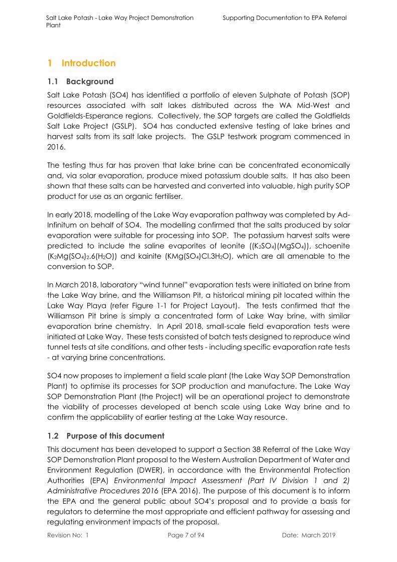
1.1 BackgroundSalt Lake Potash (SO4) has identified a portfolio of eleven Sulphate of Potash (SOP) resources associated with salt lakes distributed across the WA Mid-West and Goldfields-Esperance regions. Collectively, the SOP targets are called the Goldfields Salt Lake Project (GSLP). SO4 has conducted extensive testing of lake brines and harvest salts from its salt lake projects. The GSLP testwork program commenced in 2016.
The testing thus far has proven that lake brine can be concentrated economically and, via solar evaporation, produce mixed potassium double salts. It has also been shown that these salts can be harvested and converted into valuable, high purity SOP product for use as an organic fertiliser.
In early 2018, modelling of the Lake Way evaporation pathway was completed by Ad-Infinitum on behalf of SO4. The modelling confirmed that the salts produced by solar evaporation were suitable for processing into SOP. The potassium harvest salts were predicted to include the saline evaporites of leonite ((K2SO4)(MgSO4)), schoenite (K2Mg(SO4)2.6(H2O)) and kainite (KMg(SO4)Cl.3H2O), which are all amenable to the conversion to SOP.
In March 2018, laboratory “wind tunnel” evaporation tests were initiated on brine from the Lake Way brine, and the Williamson Pit, a historical mining pit located within the Lake Way Playa (refer Figure 1-1 for Project Layout). The tests confirmed that the Williamson Pit brine is simply a concentrated form of Lake Way brine, with similar evaporation brine chemistry. In April 2018, small-scale field evaporation tests were initiated at Lake Way. These tests consisted of batch tests designed to reproduce wind tunnel tests at site conditions, and other tests - including specific evaporation rate tests - at varying brine concentrations.
SO4 now proposes to implement a field scale plant (the Lake Way SOP Demonstration Plant) to optimise its processes for SOP production and manufacture. The Lake Way SOP Demonstration Plant (the Project) will be an operational project to demonstratethe viability of processes developed at bench scale using Lake Way brine and to confirm the applicability of earlier testing at the Lake Way resource.
1.2 Purpose of this documentThis document has been developed to support a Section 38 Referral of the Lake Way SOP Demonstration Plant proposal to the Western Australian Department of Water and Environment Regulation (DWER), in accordance with the Environmental Protection Authorities (EPA) Environmental Impact Assessment (Part IV Division 1 and 2) Administrative Procedures 2016 (EPA 2016). The purpose of this document is to informthe EPA and the general public about SO4’s proposal and to provide a basis for regulators to determine the most appropriate and efficient pathway for assessing and regulating environment impacts of the proposal.
Salt Lake Potash - Lake Way Project Demonstration Plant
Supporting Document to EPA Referral
Revision No: 1 Page 8 of 94 Date: March 2019
This document provides a summary of the potential environmental risks associated with the development and implementation of the Project and:
Describes the biophysical and social context in which the Project will operate.
Identifies key environmental factors associated with the Project.
Summarises the regulatory requirements and policy objectives relevant to those factors.
Identifies potential environmental impacts associated with the implementation of the Project.
Describes the management framework that would be used to avoid, minimise, manage, monitor and rectify impacts.
1.3 Proponent Details
The proponent for the Project is Salt Lake Potash Limited (SO4). SO4 is a company incorporated in Australia and is listed on the Australian Stock Exchange (SO4).
All compliance and regulatory requirements regarding this assessment document should be forwarded by email, post or courier to the following address:
Name: Mr Tony Swiericzuk
Company: Salt Lake Potash Limited
Title: Chief Executive Officer
Address: 239 Adelaide Terrace, Perth WA 6000
Phone: (08) 6559 5800
Email: [email protected]
CREATED BY DATE REVISIONJOB NUMBER
!
!
!
!
!
!
PERTH
LEONORA
KALBARRI
MEEKATHARRA
KALGOORLIE-BOULDER
LOCALITY MAP
180025 28/02/2019 0
COPYRIGHT: this document remains the property of Pendragon Environmental Solutions; it was prepared for the exclusive use of the authorised recipient(s) and may not be used, copied or re-produced in whole, or in part, for any purpose(s) other than that for which it was prepared for. No responsibility or liability to any other party is accepted by the use of this document without written consent.
ENVIRONMAPS
0 0.5 1 1.5 2
km
LegendLake Development EnvelopeTenement BoundaryOn Lake PondsIndicative Pond LayoutDemonstration Process PlantDevelopment EnvelopeIndicative Plant SiteWilliamson PitLake Way CausewayAccess RoadProcess Water PipelineBrine PipelineTrench
GOLDFIELDS HWY
GOLDFIELDS HWY
E 53/1905
E 53/2049
M 53/121
M 53/122
M 53/123
M 53/147
M 53/253
M 53/796
M 53/797
M 53/798
M 53/910
E 53/1878
E 53/2057
RECOVERYPONDS
KAINITE POND
HALITE POND
HALITESTOCKPILE
CARNALLITEPOND
BITTERNSPOND
120°20'0"E
120°20'0"E
C:\GIS\Jobs\Pendragon\180025 - Salt Lake Potash Lakeway Referral\Figures\180025_F1-1 Project Layout_190228.mxd
Client:
FIGURE 1-1PROJECT LAYOUT
±Scale: 1:50,000 @ A3GDA 1994 MGA Zone 51
- NOTE THAT POSITION ERRORS CAN BE >5M IN SOME AREAS- LOCALITY MAP SOURCED LANDGATE 2006- AERIAL PHOTOGRAPHY SOURCED ESRI WORLD IMAGERY
t: 040
6 590
006
www.e
nviro
nmap
s.com
.au
Salt Lake Potash - Lake Way Project Demonstration Plant
Supporting Documentation to EPA Referral
Revision No: 1 Page 10 of 94 Date: March 2019
2 Proposal Overview
SO4 proposes to develop and operate the Lake Way SOP Demonstration Plant (the Project). The Project will extract and evaporate natural brines to produce up to 50,000 tonnes per year of Sulphate of Potash (SOP), a high-quality product used in the fertiliser industry. The Project is located in and around Lake Way, approximately 25 km south of the town of Wiluna, Western Australia.
The activities and infrastructure included in this referral are:
On-playa infrastructure: brine extraction trenches, pond infrastructure and associated pipework.
Off-playa infrastructure: processing plant, process water pipework and associated infrastructure.
This Project is to be constructed on existing mining tenure (Matilda Mining Operation)held by Kimba Resources, a wholly owned subsidiary of Blackham Resources Limited (Blackham). SO4 and Blackham have a services agreement that allows for the extraction of potassium-bearing brines from groundwater beneath Kimba Resources’ tenements. The agreement also allows SO4 to establish infrastructure on Kimba’s tenements at Lake Way, with agreed processes for managing liability associated withmine closure and rehabilitation. Lake Way has been a site of historical mining activity, with the Williamson Pit operating intermittently over the past twenty years (Figure 2-1). This pit is currently operated by Blackham as part of its Matilda gold mining operations.
Salt Lake Potash - Lake Way Project Demonstration Plant
Supporting Document to EPA Referral
Revision No: 1 Page 11 of 94 Date: March 2019
Figure 2-1: Aerial view of Blackham’s Williamson pit at Lake Way
2.1 Key Project ObjectivesThe objectives of the Project are:
Demonstrate the feasibilities of commercial scale production of SOP in Western Australia.
Confirm construction methodology for on lake ponds and trenches.
Confirm optimum processing plant equipment required for full scale commercial operation.
Optimise operations to minimise costs.
Optimise power sources and power requirements for full scale commercial operation.
Optimise transport and logistics including export from port.
Optimise design for ponds, trenches, process plant and infrastructure.
Confirm resource definition and suitability of lake playa for resource extraction.
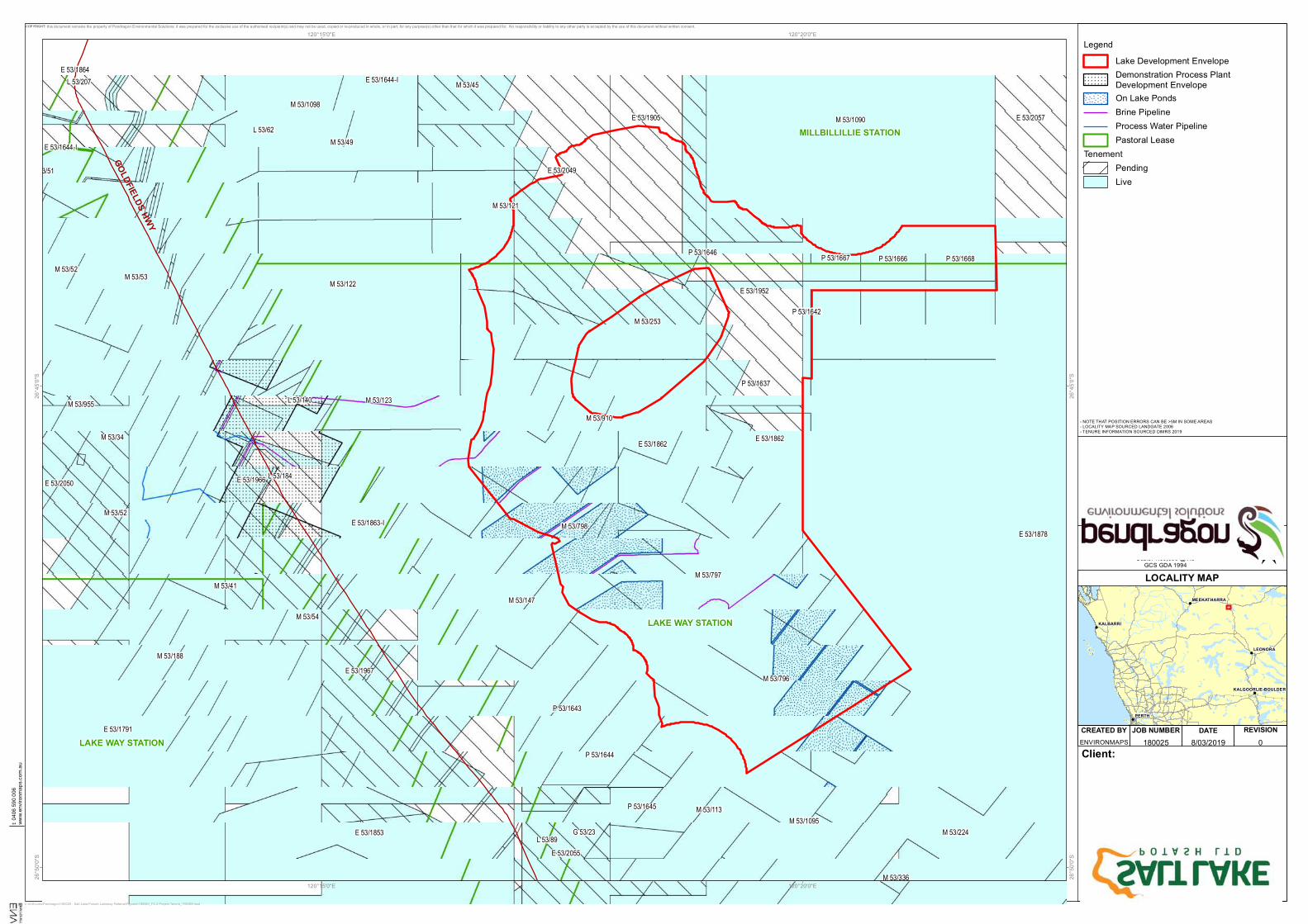
2.2 Proposal Location and TenureThe Project is located approximately 25 km south of the town of Wiluna, within the Shire of Wiluna (Figure 2-2). Access to the Project is via the Goldfields Highway, using the
Salt Lake Potash - Lake Way Project Demonstration Plant
Supporting Document to EPA Referral
Revision No: 1 Page 12 of 94 Date: March 2019
existing mine access road to the Williamson Pit.
The Project lies within the determined Native Title Claim area of the Wiluna People (WCD2013/004), managed under the Tarlku Matuwa Piarku Aboriginal Corporation (TMPAC). SO4 has entered into a Native Title Agreement (NTA) with the Native Title holders for exploration activities and those activities that support exploration. SO4 is currently engaging with TMPAC, with a view to progressing an NTA for operations of the project.
Two pastoral leases – the Lake Way and Millbillillie pastoral stations (owned by Toro Energy) underlie the Project area (Figure 2-2).
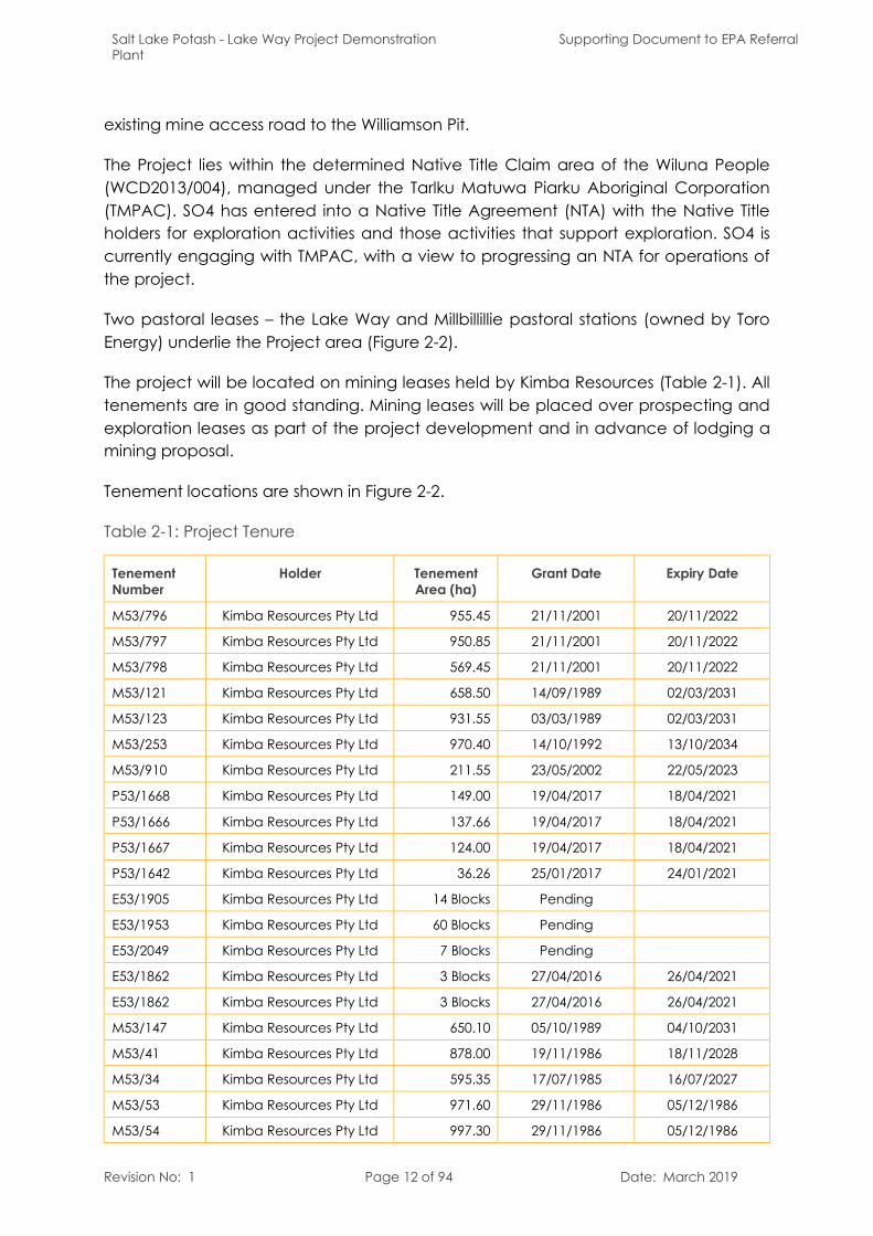
The project will be located on mining leases held by Kimba Resources (Table 2-1). All tenements are in good standing. Mining leases will be placed over prospecting and exploration leases as part of the project development and in advance of lodging a mining proposal.
Tenement locations are shown in Figure 2-2.
Table 2-1: Project Tenure
Tenement Number
Holder Tenement Area (ha)
Grant Date Expiry Date
M53/796 Kimba Resources Pty Ltd 955.45 21/11/2001 20/11/2022
M53/797 Kimba Resources Pty Ltd 950.85 21/11/2001 20/11/2022
M53/798 Kimba Resources Pty Ltd 569.45 21/11/2001 20/11/2022
M53/121 Kimba Resources Pty Ltd 658.50 14/09/1989 02/03/2031
M53/123 Kimba Resources Pty Ltd 931.55 03/03/1989 02/03/2031
M53/253 Kimba Resources Pty Ltd 970.40 14/10/1992 13/10/2034
M53/910 Kimba Resources Pty Ltd 211.55 23/05/2002 22/05/2023
P53/1668 Kimba Resources Pty Ltd 149.00 19/04/2017 18/04/2021
P53/1666 Kimba Resources Pty Ltd 137.66 19/04/2017 18/04/2021
P53/1667 Kimba Resources Pty Ltd 124.00 19/04/2017 18/04/2021
P53/1642 Kimba Resources Pty Ltd 36.26 25/01/2017 24/01/2021
E53/1905 Kimba Resources Pty Ltd 14 Blocks Pending
E53/1953 Kimba Resources Pty Ltd 60 Blocks Pending
E53/2049 Kimba Resources Pty Ltd 7 Blocks Pending
E53/1862 Kimba Resources Pty Ltd 3 Blocks 27/04/2016 26/04/2021
E53/1862 Kimba Resources Pty Ltd 3 Blocks 27/04/2016 26/04/2021
M53/147 Kimba Resources Pty Ltd 650.10 05/10/1989 04/10/2031
M53/41 Kimba Resources Pty Ltd 878.00 19/11/1986 18/11/2028
M53/34 Kimba Resources Pty Ltd 595.35 17/07/1985 16/07/2027
M53/53 Kimba Resources Pty Ltd 971.60 29/11/1986 05/12/1986
M53/54 Kimba Resources Pty Ltd 997.30 29/11/1986 05/12/1986
Salt Lake Potash - Lake Way Project Demonstration Plant
Supporting Document to EPA Referral
Revision No: 1 Page 13 of 94 Date: March 2019
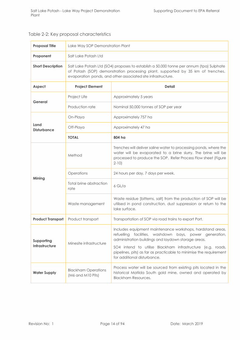
2.3 Key Proposal CharacteristicsKey proposal characteristics for the Project are summarised in Table 2-2. A conceptualsite layout is shown in Figure 1-1.
Two development envelope areas have been defined for the Project. The two development envelopes reflect the different environments between the on- andoff-playa areas associated with the project. The on-playa development envelope totals 5,290ha however is devoid of native vegetation; the off-playa development envelope totals 436 ha. Minimal vegetation clearing will be necessary to establish off-playa infrastructure.
The estimated disturbance footprint for the project is approximately 804 ha, of which757 ha (94%) is within the On-Playa Development Envelope and 47 ha (6%) is withinthe Off-Playa Development Envelope. Indicative land disturbance areas for keycomponents of the Lake Way Potash Project for each development envelope areshown in Table 2-3.
Salt Lake Potash - Lake Way Project Demonstration Plant
Supporting Document to EPA Referral
Revision No: 1 Page 14 of 94 Date: March 2019
Table 2-2: Key proposal characteristics
Proposal Title Lake Way SOP Demonstration Plant
Proponent Salt Lake Potash Ltd
Short Description Salt Lake Potash Ltd (SO4) proposes to establish a 50,000 tonne per annum (tpa) Sulphate of Potash (SOP) demonstration processing plant, supported by 35 km of trenches,evaporation ponds, and other associated site infrastructure.
Aspect Project Element Detail
GeneralProject Life Approximately 5 years
Production rate Nominal 50,000 tonnes of SOP per year
Land Disturbance
On-Playa Approximately 757 ha
Off-Playa Approximately 47 ha
TOTAL 804 ha
Mining
Method
Trenches will deliver saline water to processing ponds, where the water will be evaporated to a brine slurry. The brine will be processed to produce the SOP. Refer Process Flow sheet (Figure 2-10)
Operations 24 hours per day, 7 days per week.
Total brine abstraction rate
6 GL/a
Waste managementWaste residue [bitterns, salt] from the production of SOP will be utilised in pond construction, dust suppression or return to the lake surface.
Product Transport Product transport Transportation of SOP via road trains to export Port.
Supporting Infrastructure Minesite infrastructure
Includes equipment maintenance workshops, hardstand areas, refuelling facilities, washdown bays, power generation, administration buildings and laydown storage areas.
SO4 intend to utilise Blackham infrastructure (e.g. roads, pipelines, pits) as far as practicable to minimise the requirement for additional disturbance.
Water Supply Blackham Operations (M6 and M10 Pits)
Process water will be sourced from existing pits located in the historical Matilda South gold mine, owned and operated by Blackham Resources.
CREATED BY DATE REVISIONJOB NUMBER
!
!
!
!
!
!
PERTH
LEONORA
KALBARRI
MEEKATHARRA
KALGOORLIE-BOULDER
LOCALITY MAP
180025 8/03/2019 0
COPYRIGHT: this document remains the property of Pendragon Environmental Solutions; it was prepared for the exclusive use of the authorised recipient(s) and may not be used, copied or re-produced in whole, or in part, for any purpose(s) other than that for which it was prepared for. No responsibility or liability to any other party is accepted by the use of this document without written consent.
ENVIRONMAPS
0 0.5 1 1.5 2
km
LegendLake Development EnvelopeDemonstration Process PlantDevelopment EnvelopeOn Lake PondsBrine PipelineProcess Water PipelinePastoral Lease
TenementPendingLive
E 53/1878
M 53/1090
M 53/54
M 53/53
M 53/41
E 53/1791
M 53/796
M 53/123
M 53/122
E 53/1853
E 53/1967
E 53/1863-I
M 53/34
M 53/188
M 53/49
M 53/224
E 53/1966
E 53/1644-I
E 53/2050
G 53/23
E 53/1905
L 53/89
M 53/52
M 53/1095
E 53/2055
E 53/2057M 53/1098
E 53/1864M 53/45
L 53/140
M 53/113
M 53/52
E 53/1644-I
P 53/1643
P 53/1644
L 53/207
P 53/1645
MILLBILLILLIE STATION
LAKE WAY STATION
LAKE WAY STATION
GOLDFIELDS HWY
E 53/2049
M 53/253
M 53/797
M 53/121
M 53/147
M 53/798
E 53/1952
E 53/1862
M 53/910
E 53/1862
P 53/1668P 53/1666
L 53/184
P 53/1667
P 53/1642
L 53/62
P 53/1637
M 53/336
P 53/1646
L 53/30M 53/955
L 53/51
120°20'0"E
120°20'0"E
120°15'0"E
120°15'0"E26
°45'0
"S
26°4
5'0"S
26°5
0'0"S
26°5
0'0"S
C:\GIS\Jobs\Pendragon\180025 - Salt Lake Potash Lakeway Referral\Figures\180025_F2-2 Project Tenure_190308.mxd
Client:
FIGURE 2-2PROJECT TENURE
±Scale: 1:60,000 @ A3GCS GDA 1994
- NOTE THAT POSITION ERRORS CAN BE >5M IN SOME AREAS- LOCALITY MAP SOURCED LANDGATE 2006- TENURE INFORMATION SOURCED DIMRS 2019
t: 040
6 590
006
www.e
nviro
nmap
s.com
.au
Salt Lake Potash - Lake Way Project Demonstration Plant
Supporting Documentation to EPA Referral
Revision No: 1 Page 16 of 94 Date: March 2019
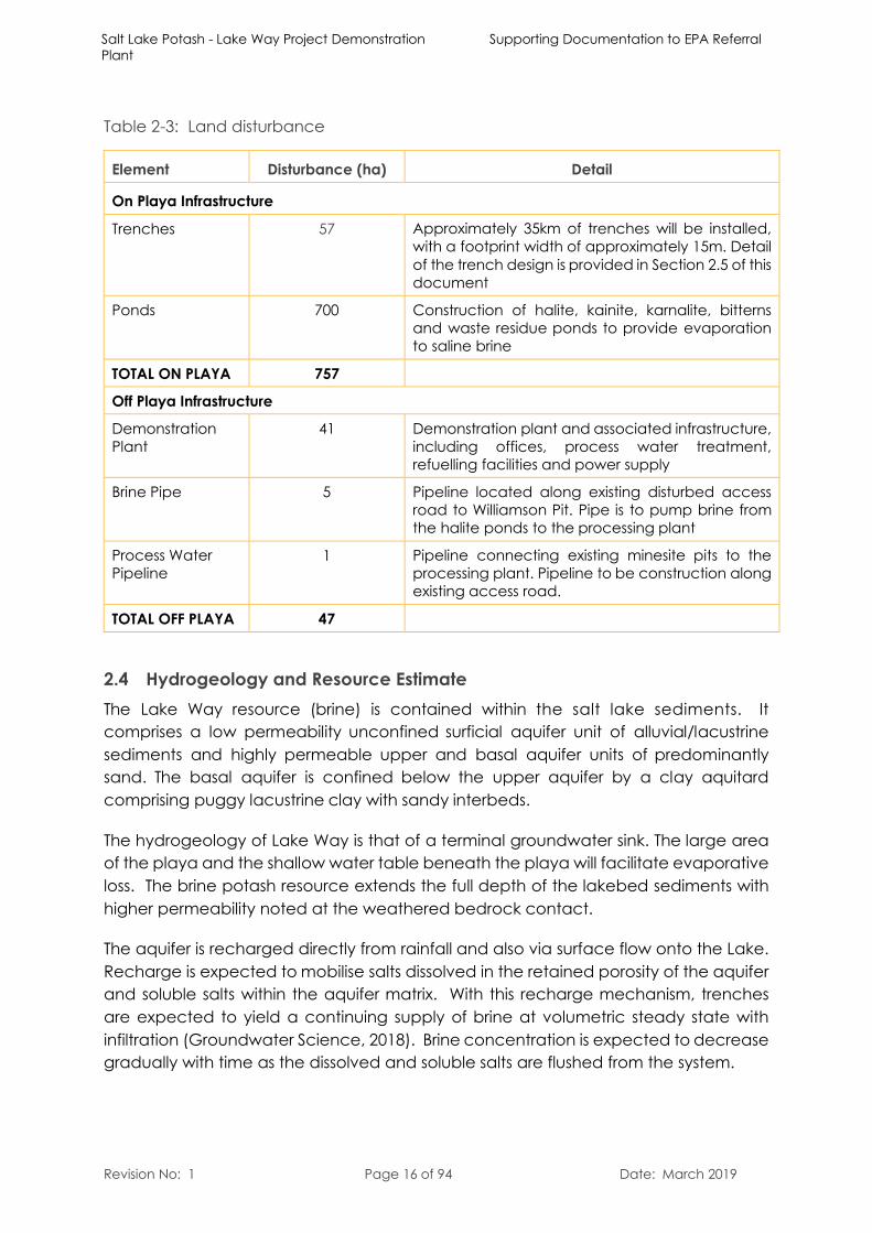
Table 2-3: Land disturbance
Element Disturbance (ha) Detail
On Playa Infrastructure
Trenches 57 Approximately 35km of trenches will be installed, with a footprint width of approximately 15m. Detail of the trench design is provided in Section 2.5 of this document
Ponds 700 Construction of halite, kainite, karnalite, bitterns and waste residue ponds to provide evaporation to saline brine
TOTAL ON PLAYA 757
Off Playa Infrastructure
Demonstration Plant
41 Demonstration plant and associated infrastructure, including offices, process water treatment, refuelling facilities and power supply
Brine Pipe 5 Pipeline located along existing disturbed access road to Williamson Pit. Pipe is to pump brine fromthe halite ponds to the processing plant
Process Water Pipeline
1 Pipeline connecting existing minesite pits to the processing plant. Pipeline to be construction along existing access road.
TOTAL OFF PLAYA 47
2.4 Hydrogeology and Resource EstimateThe Lake Way resource (brine) is contained within the salt lake sediments. It comprises a low permeability unconfined surficial aquifer unit of alluvial/lacustrine sediments and highly permeable upper and basal aquifer units of predominantly sand. The basal aquifer is confined below the upper aquifer by a clay aquitardcomprising puggy lacustrine clay with sandy interbeds.
The hydrogeology of Lake Way is that of a terminal groundwater sink. The large area of the playa and the shallow water table beneath the playa will facilitate evaporative loss. The brine potash resource extends the full depth of the lakebed sediments with higher permeability noted at the weathered bedrock contact.
The aquifer is recharged directly from rainfall and also via surface flow onto the Lake. Recharge is expected to mobilise salts dissolved in the retained porosity of the aquifer and soluble salts within the aquifer matrix. With this recharge mechanism, trenches are expected to yield a continuing supply of brine at volumetric steady state with infiltration (Groundwater Science, 2018). Brine concentration is expected to decrease gradually with time as the dissolved and soluble salts are flushed from the system.
Salt Lake Potash - Lake Way Project Demonstration Plant
Supporting Document to EPA Referral
Revision No: 1 Page 17 of 94 Date: March 2019
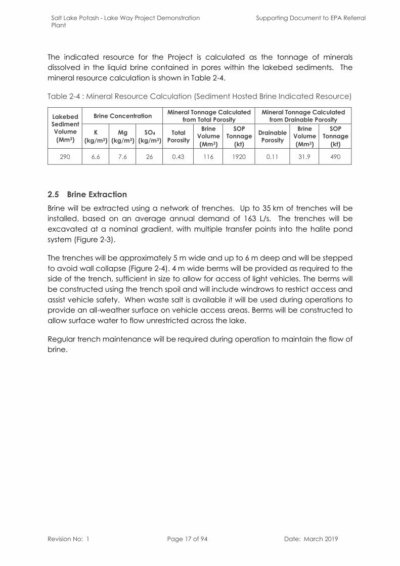
The indicated resource for the Project is calculated as the tonnage of minerals dissolved in the liquid brine contained in pores within the lakebed sediments. The mineral resource calculation is shown in Table 2-4.
Table 2-4 : Mineral Resource Calculation (Sediment Hosted Brine Indicated Resource)
Lakebed Sediment Volume(Mm3)
Brine Concentration Mineral Tonnage Calculated from Total Porosity
Mineral Tonnage Calculatedfrom Drainable Porosity
K(kg/m3)
Mg(kg/m3)
SO4
(kg/m3)Total
Porosity
Brine Volume(Mm3)
SOP Tonnage
(kt)
Drainable Porosity
Brine Volume(Mm3)
SOP Tonnage
(kt)
290 6.6 7.6 26 0.43 116 1920 0.11 31.9 490
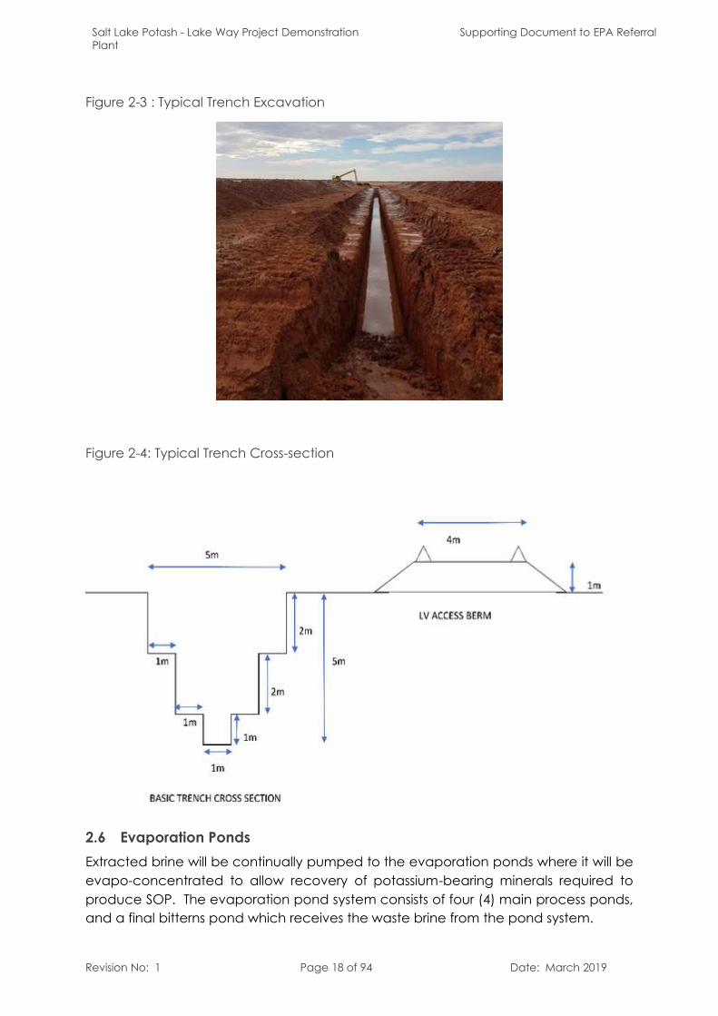
2.5 Brine ExtractionBrine will be extracted using a network of trenches. Up to 35 km of trenches will be installed, based on an average annual demand of 163 L/s. The trenches will be excavated at a nominal gradient, with multiple transfer points into the halite pond system (Figure 2-3).
The trenches will be approximately 5 m wide and up to 6 m deep and will be stepped to avoid wall collapse (Figure 2-4). 4 m wide berms will be provided as required to the side of the trench, sufficient in size to allow for access of light vehicles. The berms will be constructed using the trench spoil and will include windrows to restrict access andassist vehicle safety. When waste salt is available it will be used during operations to provide an all-weather surface on vehicle access areas. Berms will be constructed to allow surface water to flow unrestricted across the lake.
Regular trench maintenance will be required during operation to maintain the flow of brine.
Salt Lake Potash - Lake Way Project Demonstration Plant
Supporting Document to EPA Referral
Revision No: 1 Page 18 of 94 Date: March 2019
Figure 2-3 : Typical Trench Excavation
Figure 2-4: Typical Trench Cross-section
2.6 Evaporation PondsExtracted brine will be continually pumped to the evaporation ponds where it will be evapo-concentrated to allow recovery of potassium-bearing minerals required to produce SOP. The evaporation pond system consists of four (4) main process ponds, and a final bitterns pond which receives the waste brine from the pond system.
Salt Lake Potash - Lake Way Project Demonstration Plant
Supporting Document to EPA Referral
Revision No: 1 Page 19 of 94 Date: March 2019
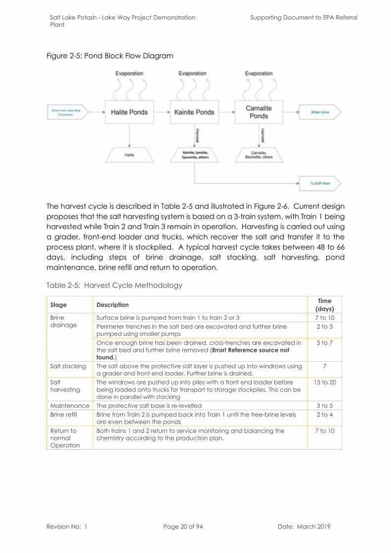
Five types of ponds (Figure 2-5) will be used at Lake Way; all these ponds will be located on-playa and have a total disturbance area of 700ha. the ponds that will be constructed are:
Halite pond;
Kainite harvest pond;
Carnalite harvest pond;
Recovery harvest pond (which receives brine flow from the process plant);
Bitterns pond (being the non-halite residue from the pond system).
Extracted brine will be concentrated in a series of solar ponds to induce the sequential precipitation of salts. The brine is pumped from the trenches into the initial evaporation pond (Halite Pond) where halite is salted out. The brine concentration is monitored to ensure that only halite salts are formed in the pond and potassium remains in the brine.
Following the Halite pond, the pregnant brine solution is pumped into the Kainite pond where the brine concentration is monitored to ensure the correct potassium salts are formed. The bulk of the potassium harvest salts are formed in the Kainite pond; the salts from this pond are harvested and the concentrated brine is sent to the Carnalite pond.
The plant produces waste brine streams due to salt dissolving in the water that is added to the process; the resultant brine is saturated in salt including potassium. To improve the overall recovery of the plant, the waste brine is sent to a Recovery Pond which evaporates water and, similar to the Kainite pond, produces potassium bearing salts. These salts are harvested and the concentrated brine is sent to the Carnalite Pond.
The residual brine from both the Kainite Pond and Recovery Pond is pumped into the Carnalite Pond to scavenge the last remaining potassium salts from the brine, which are formed as Carnallite Salt. These salts are harvested periodically.
The non-halite residue from the pond system is devoid of potassium and is the liquid reject stream for the system. It is highly concentrated in magnesium chloride and absent of most other ions. The magnesium brine is pumped to the terminal Bitterns Pond where the brine undergoes further evaporation to eventual dryness.
Salt Lake Potash - Lake Way Project Demonstration Plant
Supporting Document to EPA Referral
Revision No: 1 Page 20 of 94 Date: March 2019
Figure 2-5: Pond Block Flow Diagram
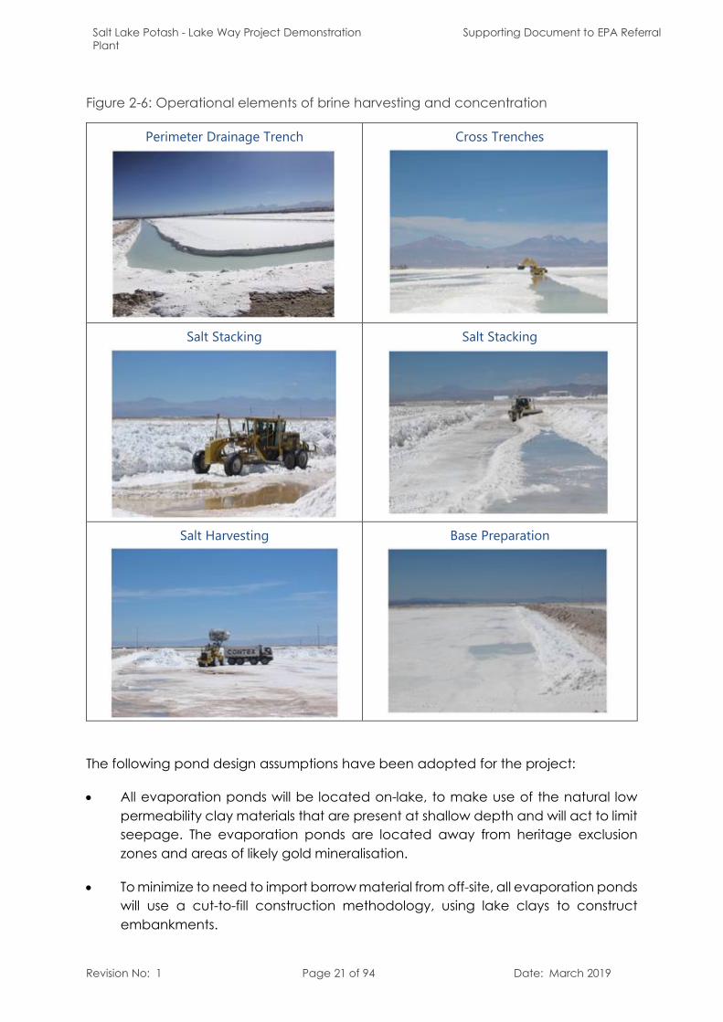
The harvest cycle is described in Table 2-5 and illustrated in Figure 2-6. Current design proposes that the salt harvesting system is based on a 3-train system, with Train 1 being harvested while Train 2 and Train 3 remain in operation. Harvesting is carried out using a grader, front-end loader and trucks, which recover the salt and transfer it to the process plant, where it is stockpiled. A typical harvest cycle takes between 48 to 66 days, including steps of brine drainage, salt stacking, salt harvesting, pond maintenance, brine refill and return to operation.
Table 2-5: Harvest Cycle Methodology
Stage Description Time(days)
Brine drainage
Surface brine is pumped from train 1 to train 2 or 3 7 to 10Perimeter trenches in the salt bed are excavated and further brine pumped using smaller pumps
2 to 3
Once enough brine has been drained, cross-trenches are excavated in the salt bed and further brine removed (Error! Reference source not found.)
5 to 7
Salt stacking The salt above the protective salt layer is pushed up into windrows using a grader and front end loader. Further brine is drained.
7
Salt harvesting
The windrows are pushed up into piles with a front end loader before being loaded onto trucks for transport to storage stockpiles. This can be done in parallel with stacking
15 to 20
Maintenance The protective salt base is re-levelled 3 to 5Brine refill Brine from Train 2 is pumped back into Train 1 until the free-brine levels
are even between the ponds2 to 4
Return to normal Operation
Both trains 1 and 2 return to service monitoring and balancing the chemistry according to the production plan.
7 to 10
Salt Lake Potash - Lake Way Project Demonstration Plant
Supporting Document to EPA Referral
Revision No: 1 Page 21 of 94 Date: March 2019
Figure 2-6: Operational elements of brine harvesting and concentration
Perimeter Drainage Trench Cross Trenches
Salt Stacking Salt Stacking
Salt Harvesting Base Preparation
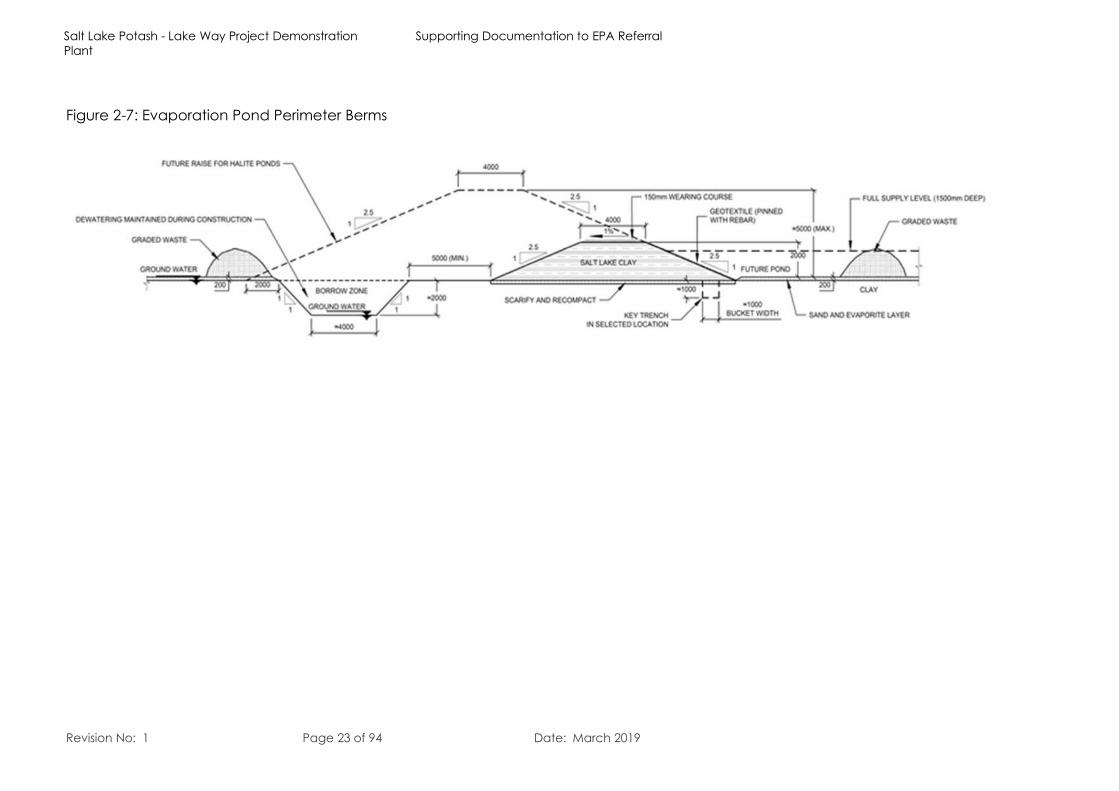
The following pond design assumptions have been adopted for the project:
All evaporation ponds will be located on-lake, to make use of the natural low permeability clay materials that are present at shallow depth and will act to limit seepage. The evaporation ponds are located away from heritage exclusion zones and areas of likely gold mineralisation.
To minimize to need to import borrow material from off-site, all evaporation ponds will use a cut-to-fill construction methodology, using lake clays to construct embankments.
Salt Lake Potash - Lake Way Project Demonstration Plant
Supporting Document to EPA Referral
Revision No: 1 Page 22 of 94 Date: March 2019
The halite and carnallite ponds will be constructed from compacted clay to reduce pond seepage. Some pond walls may require lining to minimise seepage.
The bitterns pond will be constructed from compacted clay to reduce pond seepage.
Pond construction will be undertaken on-lake using specially designed and selected earthworks equipment.
Access tracks will be incorporated into the pond wall design for access for construction, operation and maintenance. The width and embankment height of access tracks will be designed to support the selected equipment.
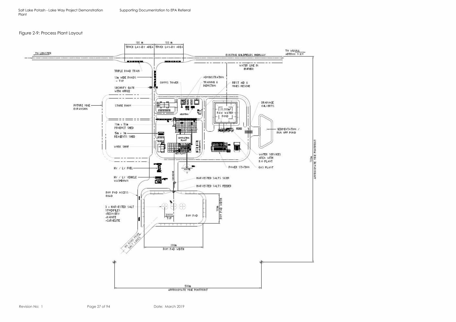
The process plant is proposed to be located close to the existing causeway that services the Williamson Pit. Harvesting haul roads from the causeway to the process plant will be constructed for the project.
Salt Lake Potash - Lake Way Project Demonstration Plant
Supporting Documentation to EPA Referral
Revision No: 1 Page 23 of 94 Date: March 2019
Figure 2-7: Evaporation Pond Perimeter Berms
Salt Lake Potash - Lake Way Project Demonstration Plant
Supporting Documentation to EPA Referral
Revision No: 1 Page 24 of 94 Date: March 2019
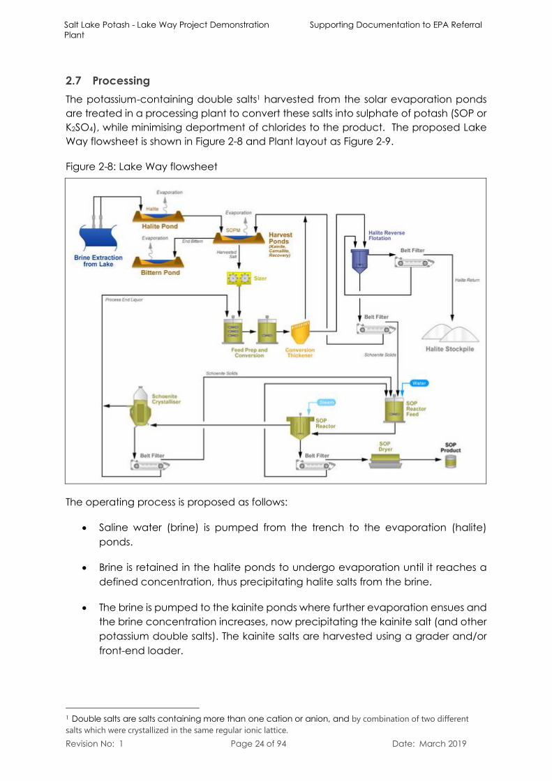
2.7 ProcessingThe potassium-containing double salts1 harvested from the solar evaporation ponds are treated in a processing plant to convert these salts into sulphate of potash (SOP or K2SO4), while minimising deportment of chlorides to the product. The proposed Lake Way flowsheet is shown in Figure 2-8 and Plant layout as Figure 2-9.
Figure 2-8: Lake Way flowsheet
The operating process is proposed as follows:
Saline water (brine) is pumped from the trench to the evaporation (halite) ponds.
Brine is retained in the halite ponds to undergo evaporation until it reaches a defined concentration, thus precipitating halite salts from the brine.
The brine is pumped to the kainite ponds where further evaporation ensues and the brine concentration increases, now precipitating the kainite salt (and other potassium double salts). The kainite salts are harvested using a grader and/or front-end loader.
1 Double salts are salts containing more than one cation or anion, and by combination of two different salts which were crystallized in the same regular ionic lattice.
Salt Lake Potash - Lake Way Project Demonstration Plant
Supporting Document to EPA Referral
Revision No: 1 Page 25 of 94 Date: March 2019
Salts are also formed in a similar manner in the Recovery pond and Carnalite pond and are harvested in the same way.
The harvested salts will be loaded onto trucks and transported to the processing plant ROM stockpile area.
The harvested salt will then be crushed in two phases: a) in a roll mill to break up the lump material and b) in attritioning cells to break down and separate the different salt species in a dense slurry.
The salt slurry is pumped into the conversion circuit, where the kainite salts are converted to schoenite prior to flotation.
To minimise chloride and sodium reporting to the product, the converted harvest salt is passed through a reverse flotation circuit. The flotation step removes waste halite feed salts and produces a solids waste stream of halite salt.
The process plant uses water to convert the harvest salts to SOP and in the process removes impurities by dissolving unwanted salts into the reject brine stream. The reject brine stream from the plant reports to the recovery pond, which in turn reports to the carnallite pond, and eventually the Bitterns pond. The brine flow to the bitterns pond is devoid of potassium but retains concentrated salts from the initial lake brine.
There are two waste streams generated by the process:
o Solid Waste – dewatered Halite salt from flotation (approximately 200,000tonnes per annum) transported to the Halite stockpile on lake.
o Liquid Waste – liquid bitterns, consisting predominantly of concentrated magnesium chloride (MgCl2) brine from the Pond System (approximately 200,000 tonnes per annum), which is pumped from the Carnallite Pond to the Bitterns Pond on lake.
The waste halite from flotation concentrated dewatered salt, predominantly NaCl, and the bitterns is essentially concentrated lake brine (predominantly MgCl2) and does not pose any environmental risk when returned to the playa surface. SO4 plan to maximise the value of these waste streams by:
o Using waste halite for construction purposes for on-playa infrastructure;
o Use bitterns brine as a dust suppressant on roads and causeways on-playa;
o Direct returned to the lake surface or disused trenches; or
Salt Lake Potash - Lake Way Project Demonstration Plant
Supporting Document to EPA Referral
Revision No: 1 Page 26 of 94 Date: March 2019
The use of the salts for the construction of infrastructure allows for the best reuse of the material, whilst reducing the need to source additional construction materials.
SO4 intend to investigate these options further and provide more detail as part of the Mine Closure Plan and Mining Proposal under the Mining Act 1978.
The flotation product, schoenite salt, is mixed with water to form a slurry and heated to 50oC in the SOP Reactor to convert the schoenite salt into SOP. This reaction produces the SOP product and a brine stream (SOP mother liquor) containing magnesium sulphate and dissolved schoenite.
The SOP mother liquor is cooled to precipitate secondary schoenite from the liquor, which is recycled to the SOP crystalliser. The cooled mother liquor is rich in sulphate and recycled to the start of the process for the conversion of harvest salts to schoenite.
The SOP product from the SOP crystalliser is filtered then dried in a rotary drier and then conveyed to the product storage shelter, where it is stacked.
Product is periodically reclaimed by a front-end loader and bagged in bulk bags to be transported to the market.
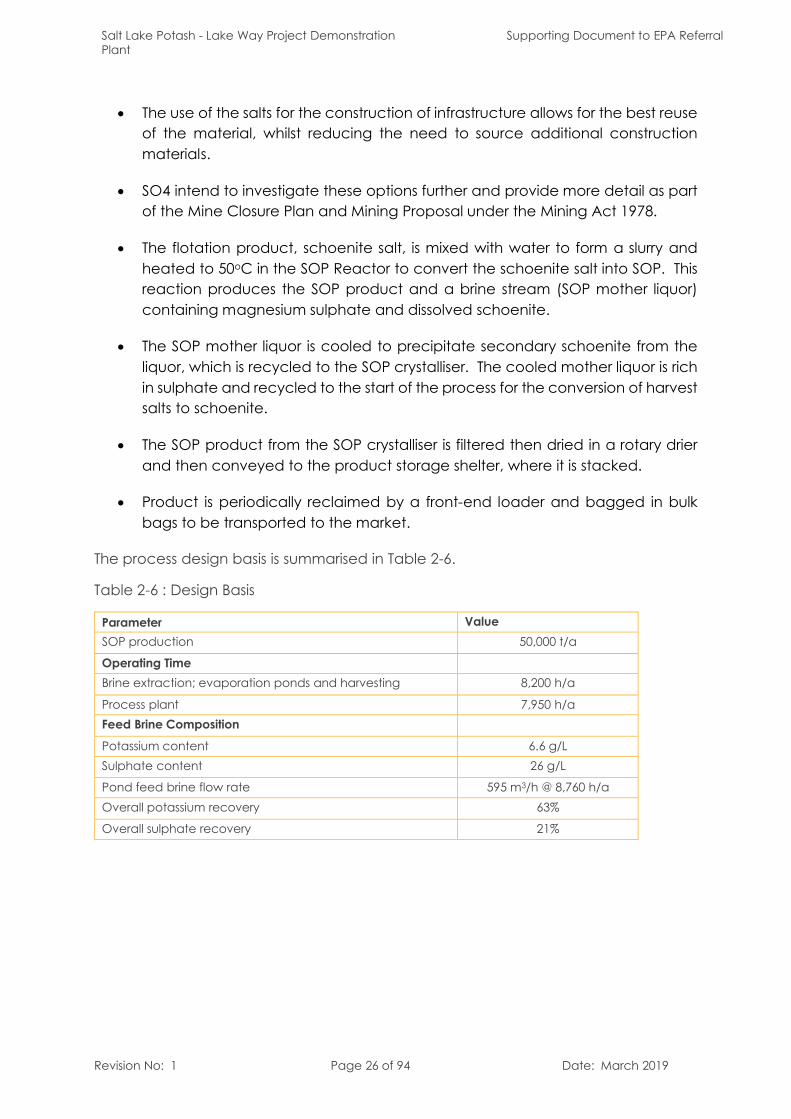
The process design basis is summarised in Table 2-6.
Table 2-6 : Design Basis
Parameter ValueSOP production 50,000 t/a
Operating TimeBrine extraction; evaporation ponds and harvesting 8,200 h/a
Process plant 7,950 h/aFeed Brine Composition
Potassium content 6.6 g/LSulphate content 26 g/L
Pond feed brine flow rate 595 m3/h @ 8,760 h/aOverall potassium recovery 63%
Overall sulphate recovery 21%
Salt Lake Potash - Lake Way Project Demonstration Plant
Supporting Documentation to EPA Referral
Revision No: 1 Page 27 of 94 Date: March 2019
Figure 2-9: Process Plant Layout

Salt Lake Potash - Lake Way Project Demonstration Plant
Supporting Document to EPA Referral
Revision No: 1 Page 28 of 94 Date: March 2019
This page has been left intentionally blank
Salt Lake Potash - Lake Way Project Demonstration Plant
Supporting Documentation to EPA Referral
Revision No: 1 Page 29 of 94 Date: March 2019
2.8 Process water supplyThe project will require 0.3 GL per annum of fresh to brackish water for processing and other ancillary uses such as potable water. This water supply is proposed to be obtained from the existing pits located on Blackhams lease, being pits M6 and M10 (refer Figure 2-10). A review of the available water from these pits has identified that they have sufficient volume to meet 3 years’ of operations2.
2.9 Major InfrastructureThe project is located in close proximity to the Goldfields Highway which is a state highway that extends 800 km from south of Kambalda in the Goldfields to Meekatharra in the Mid-West. Given the proximity to the Goldfields Highway, road haulage options include either travelling south toward Leonora or west to Geraldton.
The process plant is located 7 km from the evaporation ponds and is connected to the pond complex by an existing haul road that services the Williamson Pit.
Power required for the plant totals 2 MW installed with an operating requirement of 1.4 MW. Due to the short nature of the project, SO4 plan to install diesel generators to provide power for the project.
Power to remote locations such as the process water pit and the extraction and evaporation pond areas will be supplied by diesel generator sets.
A fly in/fly out (FIFO) workforce has been adopted for the project using the Wiluna airport, which is located 5 km south of the main township. It is proposed to utilise existing accommodation facilities including Blackham accommodation village which services the nearby Wiluna Gold Mine and Mount Keith. These facilities are well established and have the capacity to accommodate the SO4 workforce.
2 as the product is placed in the halite ponds for a period of 12 – 18 months prior to product being available for processing.