Embed Size (px)
Citation preview
PROFESSIONAL LAUNDRY
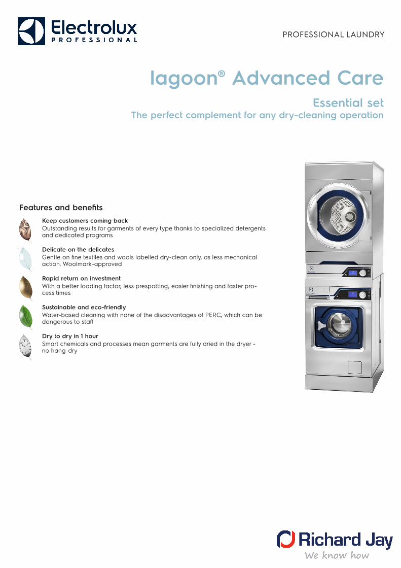
lagoon® Advanced CareEssential set
The perfect complement for any dry-cleaning operation
Features and benefitsKeep customers coming backOutstanding results for garments of every type thanks to specialized detergents and dedicated programs
Delicate on the delicatesGentle on fine textiles and wools labelled dry-clean only, as less mechanical action. Woolmark-approved
Rapid return on investmentWith a better loading factor, less prespotting, easier finishing and faster pro-cess times
Sustainable and eco-friendlyWater-based cleaning with none of the disadvantages of PERC, which can be dangerous to staff
Dry to dry in 1 hourSmart chemicals and processes mean garments are fully dried in the dryer - no hang-dry
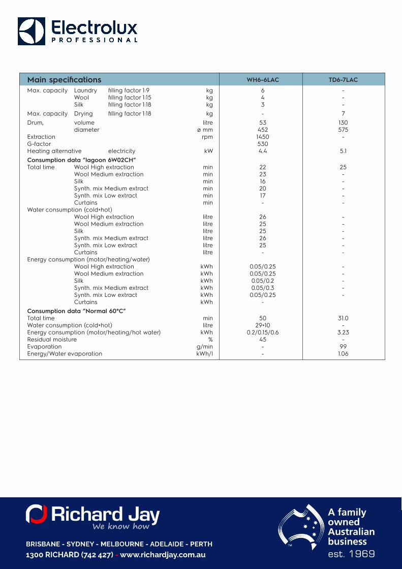
WH6-6LAC TD6-7LAC
6 - 4 - 3 -- 7
53 130 452 575 1450 - 530 4.4 5.1
22 25 23 - 16 - 20 - 17 - - -
26 - 25 - 25 - 26 - 25 - - -
0.05/0.25 - 0.05/0.25 - 0.05/0.2 - 0.05/0.3 - 0.05/0.25 -
-
50 31.0 29+10 -
0.2/0.15/0.6 3.23 45 - - 99 - 1.06
Main specificationsMax. capacity Laundry filling factor 1:9 kg
Wool filling factor 1:15 kg Silk filling factor 1:18 kg
Max. capacity Drying filling factor 1:18 kgDrum, volume litre
diameter ø mm Extraction rpm G-factorHeating alternative electricity kWConsumption data ”lagoon 6W02CH” Total time Wool High extraction min
Wool Medium extraction min Silk min Synth. mix Medium extract min Synth. mix Low extract min Curtains min
Water consumption (cold+hot) Wool High extraction litre Wool Medium extraction litre Silk litre Synth. mix Medium extract litre Synth. mix Low extract litre Curtains litre
Energy consumption (motor/heating/water) Wool High extraction kWh Wool Medium extraction kWh Silk kWh Synth. mix Medium extract kWh Synth. mix Low extract kWh Curtains kWh
Consumption data ”Normal 60°C” Total time min Water consumption (cold+hot) litre Energy consumption (motor/heating/hot water) kWh Residual moisture % Evaporation g/min Energy/Water evaporation kWh/l
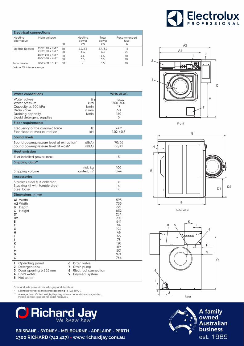
2.2/2.8 2.4/3.0 16 4.4 4.6 20 4.4 4.6 10 3.6 3.8 10
50 - 0.5 10
WH6-6LAC
3/44 200-500
17 50 160 5
24.2 1.02 ± 0.3
70/56 56/42
5
100 0.46
x x x
595 735 681 832 284 310 641 84 194 48 65 78 120 119 501 974 764
N
H
E
D2
B
7
A1A2
2
3
1 9
C
M
6
KL8
45
F
G
I
J
O
D1
Side view
Rear
Front
Electrical connections Heating Main voltage Heating Total Recommended alternative power power fuse
Hz kW kW A
Electric heated 50 50 50 50
Non heated
Water connections
Water valves iinn Water pressure kPa Capacity at 300 kPa l/min Drain valve ø mm Draining capacity l/min Liquid detergent supplies
Floor requirements
Frequency of the dynamic force Hz Floor load at max extraction kN
Sound levels
Sound power/pressure level at extraction* dB(A) Sound power/pressure level at wash* dB(A)
Heat emission
% of installed power, max
Shipping data**
net, kg Shipping volume crated, m3
Accessories
Stainless steel fluff collector Stacking kit with tumble dryer Steel base
Dimensions in mm
A1 Width A2 Width B Depth C Height D1 D2 E F G H I J K L M N O
1 Operating panel 2 Detergent box 3 Door opening ø 255 mm 4 Cold water 5 Hot water
6 Drain valve 7 Drain pump 8 Electrical connection 9 Payment system
Front and side panels in metallic grey and dark blue* Sound power levels measured according to ISO 60704.** Average data. Crated weight/shipping volume depends on configuration.
Please contact logistics for exact measures.
400V 3PH + N+E*
400V 3PH + N+E*400V 3PH + N+E*
230V 1PH + N+E*230V 1PH + N+E*
*with a 5% tolerance range
B(b)
A
1
2C
G
L
5
I
J
4
3
K
H
G
H
3
I
J
4
B(a) D
EF
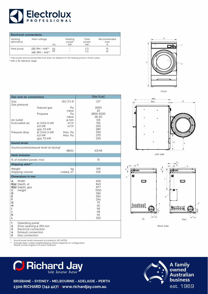
TD6-7LAC
1/2”
2000 20
2800-5000 28-50
125 150 220 280 350 270 230
63/48
15
109 0.81
600 845 877 1050 582 384 296 79 50 98 118 90 522
Front
Left side
Rear side
El Gas
* Sound power levels measured according to ISO 60704.** Average data. Crated weight/shipping volume depends on configuration.
Please contact logistics for exact measures.
Gas and air connections
Gas ISO 7/1-R Gas pressure
Natural gas Pa mbar
Propane Pa mbar
Air outlet ø mm Evacuated air, el 3.0/4.5 kW m3/h
6.0 kW m3/h gas 7.0 kW
Pressure drop el 3.0/4.5 kW Max. Pa 6.0 kW Max. Pa gas 7.0 kW
Sound levels
Sound power/pressure level at drying* dB(A)
Heat emission
% of installed power, max
Shipping data**
Weight kg Shipping volume crated, m3
Dimensions in mm
A Width B(a) Depth, el B(b) Depth, gas C HeightD E F G H I JK L
1 Operating panel 2 Door opening ø 392 mm 3 Electrical connection 4 Exhaust connection 5 Gas connection
10 5050
* 2.3 * 2.3 10
Electrical connections Heating Main v oltage Heating Total R ecommended alternativ e power power fuse
Hz kW kW A
Heat pump
* Total power and recommended fuse does not depend on the heating power in those cases.
230 1PH + N+E**400 3PH + N+E**
**with a 5% tolerance range
230V / 50Hz 115V / 60Hz
988916901 988916911
988916902 988916912
988916903 988916913
988916904 988916914
988916935 988916915
988916937 988916937
988916941 988916941
432731085 432731086
432731087 432731088
432731089 432731090
PNC
988916610
988916611
988916612
988916613
988916614
988916615
988916616
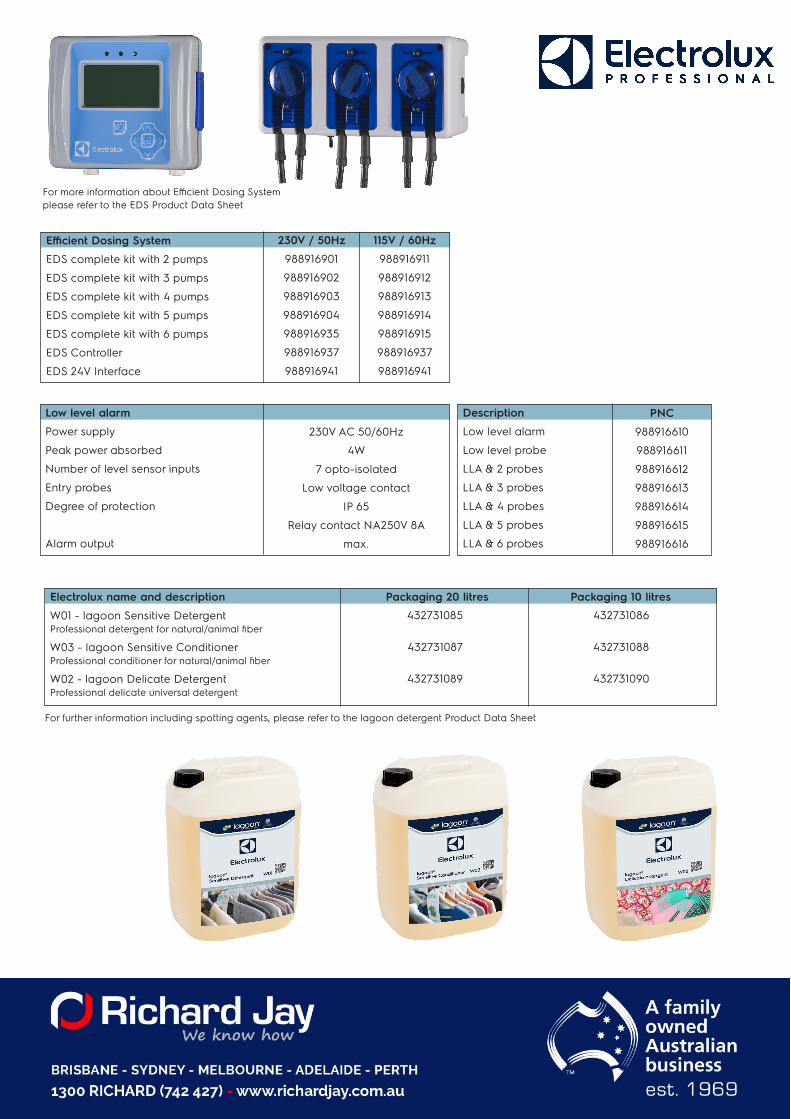
For more information about Efficient Dosing System please refer to the EDS Product Data Sheet
Efficient Dosing System
EDS complete kit with 2 pumps
EDS complete kit with 3 pumps
EDS complete kit with 4 pumps
EDS complete kit with 5 pumps
EDS complete kit with 6 pumps
EDS Controller
EDS 24V Interface
Low level alarm
Power supply
Peak power absorbed
Number of level sensor inputs
Entry probes
Degree of protection
Alarm output
Description
Low level alarm
Low level probe
LLA & 2 probes
LLA & 3 probes
LLA & 4 probes
LLA & 5 probes
LLA & 6 probes
230V AC 50/60Hz
4W
7 opto-isolated
Low voltage contact
IP 65
Relay contact NA250V 8A
max.
Electrolux name and description Packaging 20 litres Packaging 10 litres
W01 - lagoon Sensitive Detergent Professional detergent for natural/animal fiber
W03 - lagoon Sensitive Conditioner Professional conditioner for natural/animal fiber
W02 - lagoon Delicate Detergent Professional delicate universal detergent
For further information including spotting agents, please refer to the lagoon detergent Product Data Sheet
Experience the Excellenceprofessional.electrolux.com
Art.
No.
438
9139
11EN
/201
9.08
.29
We
rese
rve
the
right
to a
lter s
pec
ifica
tions
with
out
no
tice.
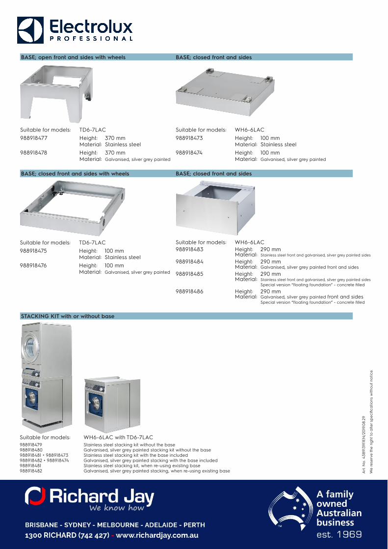
BASE; open front and sides with wheels
Suitable for models: TD6-7LAC988918477 Height: 370 mm
Material: Stainless steel988918478 Height: 370 mm
Material: Galvanised, silver grey painted
BASE; closed front and sides
Suitable for models: WH6-6LAC988918473 Height: 100 mm
Material: Stainless steel988918474 Height: 100 mm
Material: Galvanised, silver grey painted
BASE; closed front and sides with wheels BASE; closed front and sides
Suitable for models: TD6-7LAC988918475 Height: 100 mm
Material: Stainless steel988918476 Height: 100 mm
Material: Galvanised, silver grey painted
Suitable for models: WH6-6LAC988918483 Height: 290 mm
Material: Stainless steel front and galvanised, silver grey painted sides
988918484 Height: 290 mm Material: Galvanised, silver grey painted front and sides
988918485 Height: 290 mm Material: Stainless steel front and galvanised, silver grey painted sides Special version “floating foundation” - concrete filled
988918486 Height: 290 mm Material: Galvanised, silver grey painted front and sides Special version “floating foundation” - concrete filled
STACKING KIT with or without base
Suitable for models: WH6-6LAC with TD6-7LAC988918479 Stainless steel stacking kit without the base 988918480 Galvanised, silver grey painted stacking kit without the base 988918481 + 988918473 Stainless steel stacking kit with the base included 988918482 + 988918474 Galvanised, silver grey painted stacking with the base included 988918481 Stainless steel stacking kit, when re-using existing base 988918482 Galvanised, silver grey painted stacking, when re-using existing base
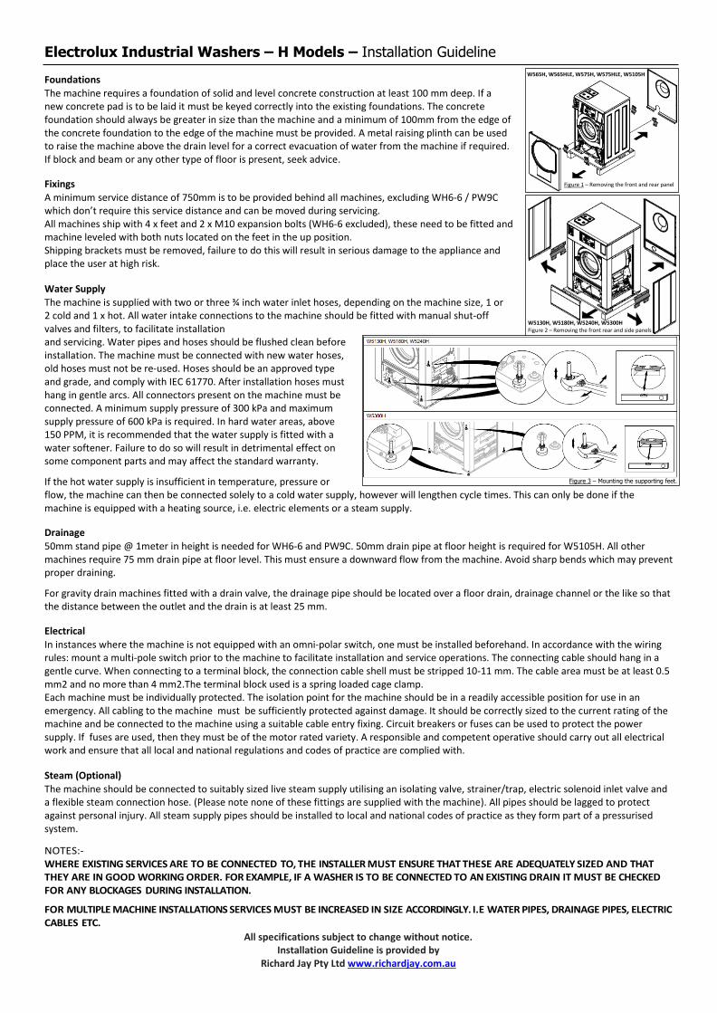
Electrolux Industrial Washers – H Models – Installation Guideline
All specifications subject to change without notice. Installation Guideline is provided by
Richard Jay Pty Ltd www.richardjay.com.au
Foundations The machine requires a foundation of solid and level concrete construction at least 100 mm deep. If a new concrete pad is to be laid it must be keyed correctly into the existing foundations. The concrete foundation should always be greater in size than the machine and a minimum of 100mm from the edge of the concrete foundation to the edge of the machine must be provided. A metal raising plinth can be used to raise the machine above the drain level for a correct evacuation of water from the machine if required. If block and beam or any other type of floor is present, seek advice.
Fixings A minimum service distance of 750mm is to be provided behind all machines, excluding WH6-6 / PW9C which don’t require this service distance and can be moved during servicing. All machines ship with 4 x feet and 2 x M10 expansion bolts (WH6-6 excluded), these need to be fitted and machine leveled with both nuts located on the feet in the up position. Shipping brackets must be removed, failure to do this will result in serious damage to the appliance and place the user at high risk.
Water Supply The machine is supplied with two or three ¾ inch water inlet hoses, depending on the machine size, 1 or 2 cold and 1 x hot. All water intake connections to the machine should be fitted with manual shut-off valves and filters, to facilitate installation and servicing. Water pipes and hoses should be flushed clean before installation. The machine must be connected with new water hoses, old hoses must not be re-used. Hoses should be an approved type and grade, and comply with IEC 61770. After installation hoses must hang in gentle arcs. All connectors present on the machine must be connected. A minimum supply pressure of 300 kPa and maximum supply pressure of 600 kPa is required. In hard water areas, above 150 PPM, it is recommended that the water supply is fitted with a water softener. Failure to do so will result in detrimental effect on some component parts and may affect the standard warranty.
If the hot water supply is insufficient in temperature, pressure or flow, the machine can then be connected solely to a cold water supply, however will lengthen cycle times. This can only be done if the machine is equipped with a heating source, i.e. electric elements or a steam supply.
Drainage 50mm stand pipe @ 1meter in height is needed for WH6-6 and PW9C. 50mm drain pipe at floor height is required for W5105H. All other machines require 75 mm drain pipe at floor level. This must ensure a downward flow from the machine. Avoid sharp bends which may prevent proper draining.
For gravity drain machines fitted with a drain valve, the drainage pipe should be located over a floor drain, drainage channel or the like so that the distance between the outlet and the drain is at least 25 mm.
Electrical In instances where the machine is not equipped with an omni-polar switch, one must be installed beforehand. In accordance with the wiring rules: mount a multi-pole switch prior to the machine to facilitate installation and service operations. The connecting cable should hang in a gentle curve. When connecting to a terminal block, the connection cable shell must be stripped 10-11 mm. The cable area must be at least 0.5 mm2 and no more than 4 mm2.The terminal block used is a spring loaded cage clamp. Each machine must be individually protected. The isolation point for the machine should be in a readily accessible position for use in an emergency. All cabling to the machine must be sufficiently protected against damage. It should be correctly sized to the current rating of the machine and be connected to the machine using a suitable cable entry fixing. Circuit breakers or fuses can be used to protect the power supply. If fuses are used, then they must be of the motor rated variety. A responsible and competent operative should carry out all electrical work and ensure that all local and national regulations and codes of practice are complied with.
Steam (Optional) The machine should be connected to suitably sized live steam supply utilising an isolating valve, strainer/trap, electric solenoid inlet valve and a flexible steam connection hose. (Please note none of these fittings are supplied with the machine). All pipes should be lagged to protect against personal injury. All steam supply pipes should be installed to local and national codes of practice as they form part of a pressurised system.
NOTES:- WHERE EXISTING SERVICES ARE TO BE CONNECTED TO, THE INSTALLER MUST ENSURE THAT THESE ARE ADEQUATELY SIZED AND THAT THEY ARE IN GOOD WORKING ORDER. FOR EXAMPLE, IF A WASHER IS TO BE CONNECTED TO AN EXISTING DRAIN IT MUST BE CHECKED FOR ANY BLOCKAGES DURING INSTALLATION.
FOR MULTIPLE MACHINE INSTALLATIONS SERVICES MUST BE INCREASED IN SIZE ACCORDINGLY. I.E WATER PIPES, DRAINAGE PIPES, ELECTRIC CABLES ETC.
Figure 1 – Removing the front and rear panel
W565H, W565HLE, W575H, W575HLE, W5105H
W5130H, W5180H, W5240H, W5300H Figure 2 – Removing the front rear and side panels
Figure 3 – Mounting the supporting feet.

Electrolux Industrial Dryers – Installation Guideline
All specifications subject to change without notice. Installation Guideline is provided by
Richard Jay Pty Ltd www.richardjay.com.au
Foundations - The machine should be sited on a firm level floor capable of withstanding its
loaded weight.
Setup - Two persons are recommended for the unpacking.
- The machine is bolted onto the transport pallet, remove the bolts between the machine and pallet. There are two bolts in the front of the machine and two in the back of the machine.
- The machine is delivered with supporting feet & must be levelled.
- The machine should be positioned so that there is plenty of room for working -(min. 500mm), both for the user and service personnel.
Electrical supply - A competent installer must carry out all work. All work and materials must
comply with local and national codes of practice.
- The machine must be installed using correctly sized cable (not provided)
- Each dryer must be provided with a separate isolation point, usually a
fused switched outlet, with it’s own circuit.
- Electrical connections are made inside the rear service box located at the
upper left of the machine. Notice must be taken of the connection diagram.
- The isolator must be in an accessible position for emergency shut off.
Gas supply - A qualified and competent person should carry out the installation of the gas
supply. All gas work must be carried out by a registered AGA gas
operative and must comply with all regulations relating to the installation.
- Ensure that the correct pressure is supplied to the dryer. Dependi6ng
upon the type of gas used if the inline pressure exceeds that which is
required a regulator should be fitted. If this is the case consult the supplier.
- The machine is designed to burn at a certain rate, known as the BTU rating of
the appliance. To ensure that this rate is maintained the gas supply should
remain constant. To achieve this the supply line must be of the correct size.
Distance from the meter and other appliances on the same supply will have
an effect on the pressure. Each dryer should have a gas isolation tap test
gauge point, and restraining wire/chain
- The machine should be connected to a supply using a flexible armoured hose
as vibrations could cause a solid connection to fracture. The hose may have
union or bayonet connection points. A bayonet connector should not be used as
an isolation point.
Exhaust - All exhaust ductwork must be designed by a competent operative to ensure that
the installation does not have any detrimental effect on dryer performance.
- The duct should follow the shortest possible route to atmosphere using the
least number of bends possible and should be constructed of a smooth wall, rigid
stainless steel or galvanised tubing. Flexible ducting must not be used.
- The diameter of the duct must never be reduced in size.
- If a common duct is to be used to vent a multiple dryer installation the diameter
shall be increased to accommodate the cumulative effect of all dryers.
- Exhaust terminations may be hooded weather cowling (china hat) for vertical ducts
or a downturn 90º elbow for horizontal. Louvres or grills may be used to prevent
entry by foreign objects but consideration must be given to potential restrictions to
air flow. When louvres and grills are used they must be in an accessible location for
regular cleaning
- The exhaust should be properly sealed at all joints (no rivets).
- The exhaust air should not be vented into a wall, a ceiling, or a concealed
space of building. Air must be vented outdoors.
Ventilation - The dryer removes a large amount of air, while it is operating, from the
room via the exhaust. Therefore, the air inside the room must be continually
replenished with fresh air from atmosphere.
- If there is an imbalance between the air being pushed out to that which is
being drawn in, there will be an adverse effect on the performance and
operation of the dryer.
- Where louvres or grills are fitted then the size should be increased to
achieve the correct size of free air space. Ventilation must be fixed and
unrestricted. Ventilation should not be positioned within two metre of
exhaust duct outlet. If more than one dryer is installed the opening can be
increased to match their requirements; there is no need to make a
separate opening.
- The area of the air inlet opening must be five times the size of the
exhaust pipe area. The area of the inlet opening is the area through
which the air can flow without resistance from the grating/slatted
cover.
Static Back Pressure - It is important to calibrate static back pressure according to ducting
provided on site, this ensures optimal energy efficiencies and best performace.
- Adjust the dryer’s damper by demounting the lower back panel and losening the screws. B in below image.
- Measure the pressure with an airflow meter by removing the NTC sensor (A) and testing the airflow, adjust the the damper until ideal pressure is reached per below table and taighten screws once achieved.
Model Heating / Frequency Static Back
Pressure
Max Airflow
T5290 Electric / 50 Hz 400 Pa 550 m3/h
T5290 Gas / 50 Hz 400 Pa 610 m3/h
T5550 Electric / 50 Hz 650 Pa 940 m3/h
T5550 Gas / 50 Hz 650 Pa 940 m3/h
T5675 Electric / 50 Hz 500 Pa 1140 m3/h
T5675 Gas / 50 Hz 750 Pa 1140 m3/h