Embed Size (px)
Citation preview
66
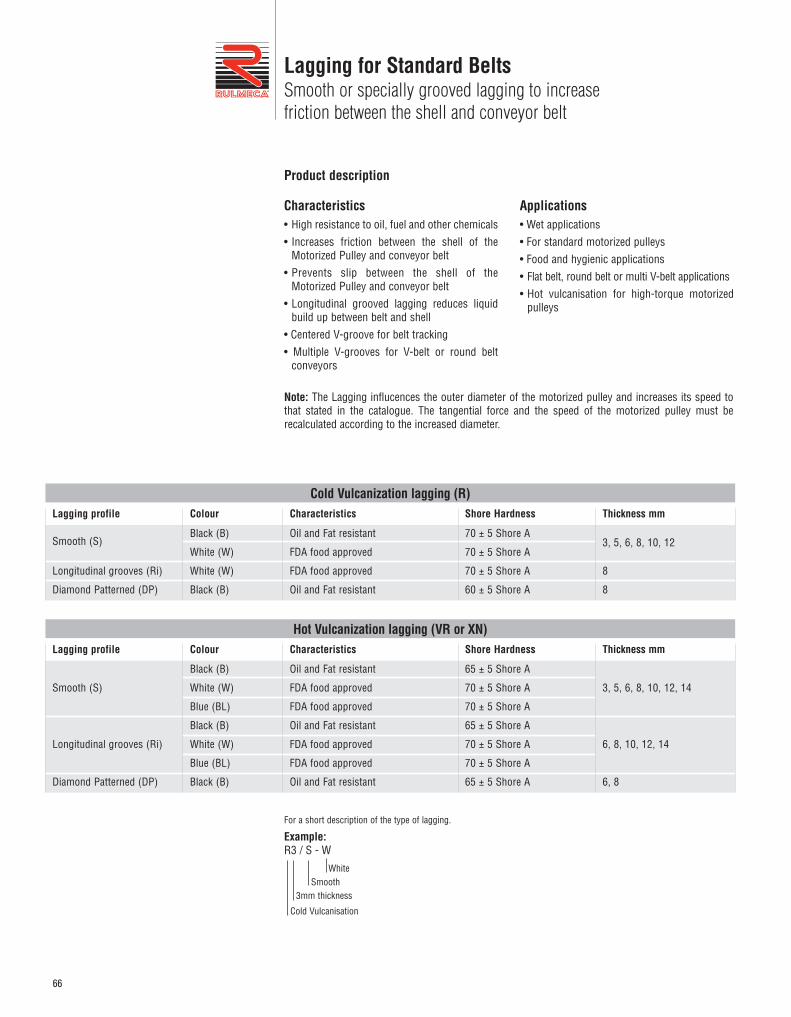
Lagging for Standard BeltsSmooth or specially grooved lagging to increase friction between the shell and conveyor belt
Applications• Wet applications• For standard motorized pulleys• Food and hygienic applications• Flat belt, round belt or multi V-belt applications• Hot vulcanisation for high-torque motorized
pulleys
Characteristics• High resistance to oil, fuel and other chemicals• Increases friction between the shell of the
Motorized Pulley and conveyor belt• Prevents slip between the shell of the
Motorized Pulley and conveyor belt• Longitudinal grooved lagging reduces liquid
build up between belt and shell • Centered V-groove for belt tracking• Multiple V-grooves for V-belt or round belt
conveyors
Product description
Lagging profile Colour Characteristics Shore Hardness
70 ± 5 Shore A
70 ± 5 Shore A
70 ± 5 Shore A
60 ± 5 Shore A
Oil and Fat resistant
FDA food approved
FDA food approved
Oil and Fat resistant
Black (B)
White (W)
White (W)
Black (B)
Smooth (S)
Longitudinal grooves (Ri)
Diamond Patterned (DP)
Thickness mm
3, 5, 6, 8, 10, 12
8
8
Cold Vulcanization lagging (R)
Lagging profile Colour Characteristics Shore Hardness
65 ± 5 Shore A
70 ± 5 Shore A
70 ± 5 Shore A
65 ± 5 Shore A
70 ± 5 Shore A
70 ± 5 Shore A
65 ± 5 Shore A
Oil and Fat resistant
FDA food approved
FDA food approved
Oil and Fat resistant
FDA food approved
FDA food approved
Oil and Fat resistant
Black (B)
White (W)
Blue (BL)
Black (B)
White (W)
Blue (BL)
Black (B)
Smooth (S)
Longitudinal grooves (Ri)
Diamond Patterned (DP)
Thickness mm
3, 5, 6, 8, 10, 12, 14
6, 8, 10, 12, 14
6, 8
Hot Vulcanization lagging (VR or XN)
Note: The Lagging influcences the outer diameter of the motorized pulley and increases its speed tothat stated in the catalogue. The tangential force and the speed of the motorized pulley must berecalculated according to the increased diameter.
For a short description of the type of lagging.
Example: R3 / S - W
Cold Vulcanisation
3mm thicknessSmooth
White
67
Lagging for Standard BeltsSmooth or specially grooved lagging to increase friction between the shell and conveyor belt
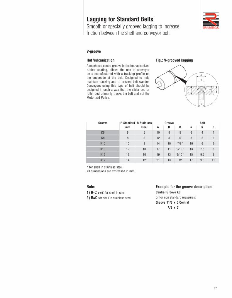
Hot VulcanizationA machined centre groove in the hot vulcanizedrubber coating, allows the use of conveyorbelts manufactured with a tracking profile onthe underside of the belt. Designed to helpmaintain tracking and to prevent belt wander.Conveyors using this type of belt should bedesigned in such a way that the slider bed orroller bed primarily tracks the belt and not theMotorized Pulley.
V-groove
C
A
a
B
b
R c
Fig.: V-grooved lagging
Groove R Standardmm
Groove A B C
Belt a b c
K6
K8
K10
K13
K15
K17
8
8
10
12
12
14
R Stainlesssteel
5
6
8
10
10
12
10
12
14
17
19
21
8
8
10
11
13
13
5
6
7/8*
9/10*
9/10*
12
6
8
10
13
15
17
4
5
6
7.5
9.5
9.5
4
5
6
8
8
11
Rule: 1) R-C >=2 for shell in steel
2) R=C for shell in stainless steel
Example for the groove description:Central Groove K6 or for non standard measures:Groove 11/8 x 5 Central A/B x C
* for shell in stainless steel.All dimensions are expressed in mm.
68
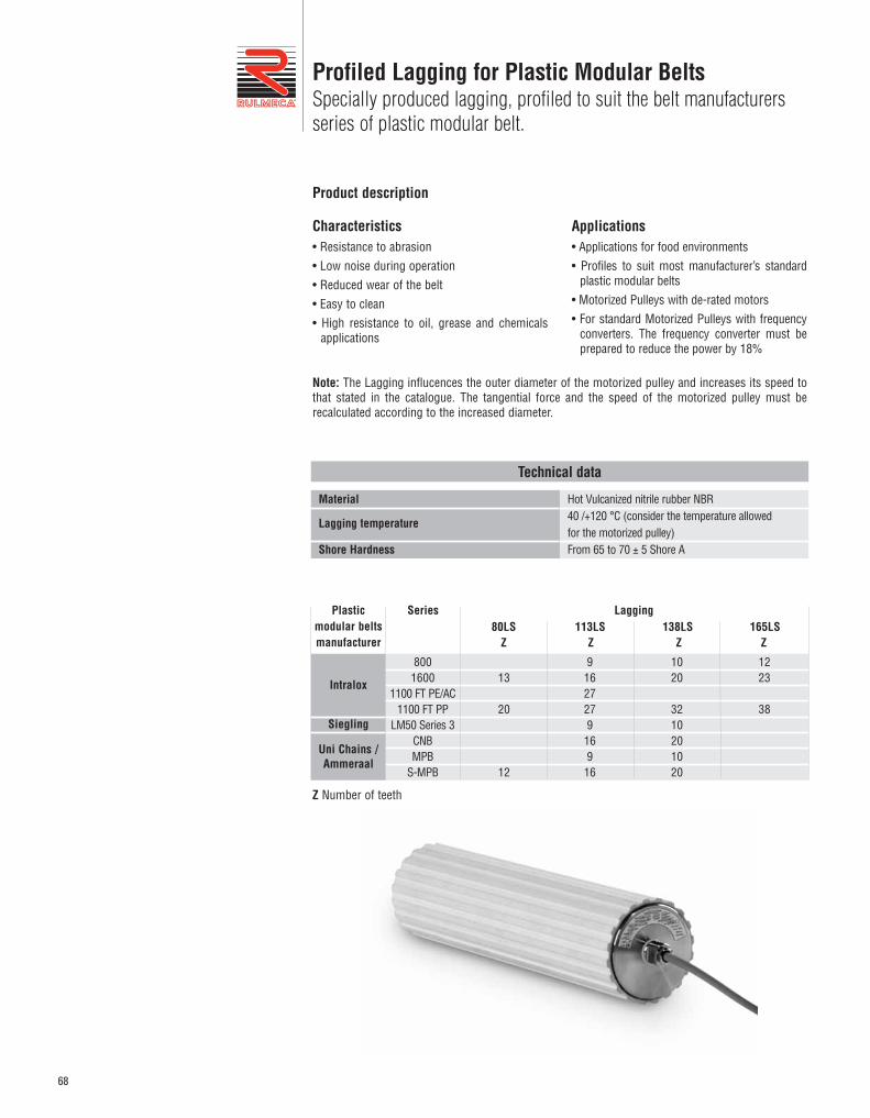
Profiled Lagging for Plastic Modular BeltsSpecially produced lagging, profiled to suit the belt manufacturersseries of plastic modular belt.
Characteristics• Resistance to abrasion• Low noise during operation• Reduced wear of the belt• Easy to clean• High resistance to oil, grease and chemicals
applications
Applications• Applications for food environments• Profiles to suit most manufacturer’s standard
plastic modular belts• Motorized Pulleys with de-rated motors• For standard Motorized Pulleys with frequency
converters. The frequency converter must beprepared to reduce the power by 18%
Product description
Technical data
Hot Vulcanized nitrile rubber NBR40 /+120 °C (consider the temperature allowed for the motorized pulley)From 65 to 70 ± 5 Shore A
Material
Lagging temperature
Shore Hardness
Note: The Lagging influcences the outer diameter of the motorized pulley and increases its speed tothat stated in the catalogue. The tangential force and the speed of the motorized pulley must berecalculated according to the increased diameter.
Plasticmodular beltsmanufacturer
Series Lagging
91627279
169
16
1020
3210201020
1223
38
13
20
12
8001600
1100 FT PE/AC1100 FT PP
LM50 Series 3CNBMPB
S-MPB
80LS 113LS 138LS 165LSZ Z Z Z
Intralox
Siegling
Uni Chains /Ammeraal
Z Number of teeth
69
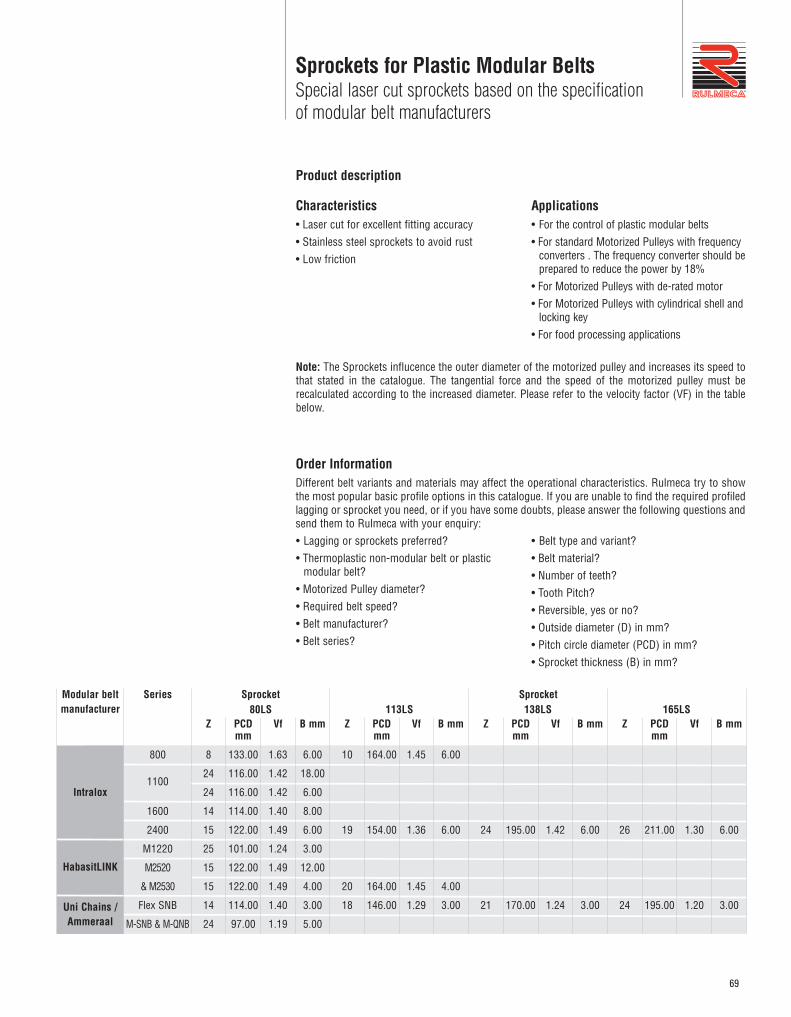
Sprockets for Plastic Modular BeltsSpecial laser cut sprockets based on the specification of modular belt manufacturers
Characteristics• Laser cut for excellent fitting accuracy• Stainless steel sprockets to avoid rust• Low friction
Applications• For the control of plastic modular belts• For standard Motorized Pulleys with frequency
converters . The frequency converter should beprepared to reduce the power by 18%
• For Motorized Pulleys with de-rated motor • For Motorized Pulleys with cylindrical shell and
locking key• For food processing applications
Product description
Note: The Sprockets influcence the outer diameter of the motorized pulley and increases its speed tothat stated in the catalogue. The tangential force and the speed of the motorized pulley must berecalculated according to the increased diameter. Please refer to the velocity factor (VF) in the tablebelow.
80LS
8
24
24
14
15
25
15
15
14
24
133.00
116.00
116.00
114.00
122.00
101.00
122.00
122.00
114.00
97.00
1.63
1.42
1.42
1.40
1.49
1.24
1.49
1.49
1.40
1.19
6.00
18.00
6.00
8.00
6.00
3.00
12.00
4.00
3.00
5.00
113LS
10
19
20
18
Z
164.00
154.00
164.00
146.00
PCDmm
1.45
1.36
1.45
1.29
Vf
6.00
6.00
4.00
3.00
B mm138LS
24
21
Z
195.00
170.00
PCDmm
1.42
1.24
Vf
6.00
3.00
B mm165LS
26
24
Z
211.00
195.00
PCDmm
1.30
1.20
Vf
6.00
3.00
B mm
Modular beltmanufacturer
Series
800
1100
1600
2400
M1220
M2520
& M2530
Flex SNB
M-SNB & M-QNB
Sprocket
Intralox
HabasitLINK
Sprocket
Z PCDmm
Vf B mm
• Lagging or sprockets preferred?• Thermoplastic non-modular belt or plastic
modular belt?• Motorized Pulley diameter?• Required belt speed?• Belt manufacturer?• Belt series?
Uni Chains /Ammeraal
Order InformationDifferent belt variants and materials may affect the operational characteristics. Rulmeca try to showthe most popular basic profile options in this catalogue. If you are unable to find the required profiledlagging or sprocket you need, or if you have some doubts, please answer the following questions andsend them to Rulmeca with your enquiry:
• Belt type and variant?• Belt material?• Number of teeth?• Tooth Pitch?• Reversible, yes or no?• Outside diameter (D) in mm?• Pitch circle diameter (PCD) in mm?• Sprocket thickness (B) in mm?
70
Sprockets for Plastic Modular BeltsSpecial laser cut sprockets based on the specificationof modular belt manufacturers
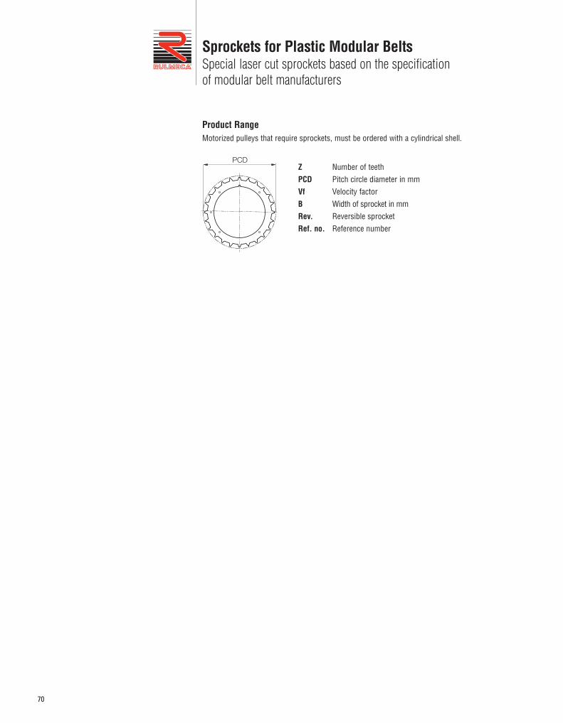
Z Number of teethPCD Pitch circle diameter in mmVf Velocity factorB Width of sprocket in mmRev. Reversible sprocketRef. no. Reference number
PCD
Product RangeMotorized pulleys that require sprockets, must be ordered with a cylindrical shell.
71
Backstop / Anti run-back bearing
Characteristics• The backstop runs only in one direction• Mounted on the rotor shaft, except for the 80LS• Mounted in the end housing on the 80LS • No need for an electrical connection• Higher holding torque than an electromagnetic
brake
Application• Single direction inclined belt conveyors• For preventing run-back of the belt and load
when the power supply is off
Product DescriptionBackstops prevent the roll-back of the belt and carried load in case of shutdown or lack of power supply.
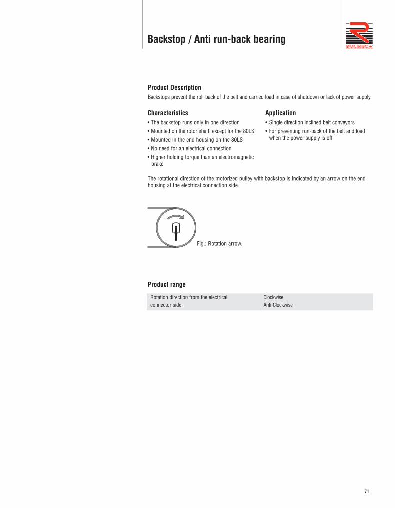
The rotational direction of the motorized pulley with backstop is indicated by an arrow on the endhousing at the electrical connection side.
Fig.: Rotation arrow.
ClockwiseAnti-Clockwise
Rotation direction from the electrical connector side
Product range
72
Electromagnetic brakes
Characteristics• Low noise• Wear contained• Powered by a separate external rectifier• Applied directly on the rotor of the motorized
pulley• When the power to the motor is lost or stopped
the brake will close (mechanically engage)
Applications• For reversible inclined and declined conveyors• For reduced stopping times*• For stopping and holding loads• For approximate positioning
Product descriptionThe Electromagnetic brake stops and holds the load in position according to the stated holding torque.
(*) For faster stopping times and accurate positioning, please use a frequency converter with brakingfunction and if necessary an encoder with feedback control.
Response timeThe response time for opening of the brake (motorized pulley start) and closing (stop motorizedpulley), may vary substantially according to:
• Type and viscosity of the oil• Level of oil in the drum motor• Ambient temperature• Internal motor working temperature• Switching at input (AC-switching) or at output
(DC-switching)
• Control contact of the coil brake into thealternating current supply of the rectifier (longresponse times), or on the output DC of therectifier (fast response)
• Type and output voltage of the rectifier controlof the brake coil
The difference between the control in alternating current and direct current is shown in the following table:
AC Switching DC Switching
Intervention time
Braking voltage
Slow
Nearly 1Volt
Fast
Nearly 500volt
Note: For the brake coil command in DC, the contacts must be protected against surges.
Reduction of braking torqueThe declared braking torque M, is strongly influenced by the operating conditions of the motorizedpulley (with oil at high temperatures) and the ambient temperature. For the calculation of the load thatcan be braked in safety, the braking torque provided in the tables should be reduced by 50%.
t 1 t 2
M
t
Fig.: Time t/Torque M brake closure
t1 Closing response time (de-excitation coil): Stop
t2 Opening response time (excitation coil): start
73
Electromagnetic brakes
Motorizedpulley
80LS
113LS
138LS
165LS
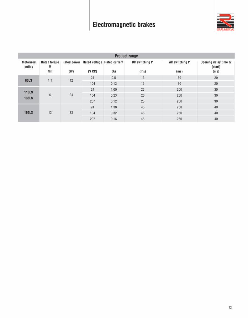
Product rangeRated torque
M(Nm)
1.1
6
12
Rated power
(W)
12
24
33
Rated voltage
(V CC)
24
104
24
104
207
24
104
207
Rated current
(A)
0.5
0.12
1.00
0.23
0.12
1.38
0.32
0.16
DC switching t1
(ms)
13
13
26
26
26
46
46
46
AC switching t1
(ms)
80
80
200
200
200
260
260
260
Opening delay time t2(start)(ms)
20
20
30
30
30
40
40
40
74
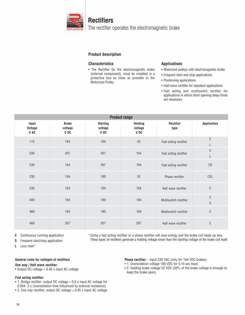
RectifiersThe rectifier operates the electromagnetic brake
Characteristics• The Rectifier for the electromagnetic brake
(external component), must be installed in aprotective box as close as possible to theMotorized Pulley
Applications• Motorized pulleys with electromagnetic brake• Frequent start and stop applications • Positioning applications• Half-wave rectifier for standard applications• Fast acting and multiswitch rectifier for
applications in which short opening delay timesare necessary
Product description
104
207
104
104
104
104
104
207
Product range
104
207
207
190
104
180
180
207
52
104
104
52
104
104
104
207
Fast acting rectifier
Fast acting rectifier
Fast acting rectifier
Phase rectifier
Half wave rectifier
Multiswitch rectifier
Multiswitch rectifier
Half wave rectifier
C
L
C
L
CS
CSL
C
C
S
C
C
115
230
230
230
230
400
460
460
C Continuous running applicationS Frequent start/stop applicationL Less heat*
*Using a fast acting rectifier or a phase rectifier will save energy and the brake coil heats up less. These types of rectifiers generate a holding voltage lower than the starting voltage of the brake coil itself.
Input Voltage
V AC
Brake voltage
V DC
Starting voltage
V DC
Holding voltage
V DC
Rectifier type
Application
General rules for voltages of rectifiersOne way / Half wave rectifier:• Output DC voltage = 0.45 x input AC voltage
Fast acting rectifier:• 1. Bridge rectifier: output DC voltage = 0.9 x input AC voltage for
0.004- 2 s (overexitation time influenced by external resistance)• 2. One way rectifier: output DC voltage = 0.45 x input AC voltage
Phase rectifier: - input 230 VAC (only for 104 VDC brakes)• 1. Overexitation voltage 190 VDC for 0.15 sec fixed• 2. Holding brake voltage 52 VDC (50% of the brake voltage is enough to
keep the brake open)
75
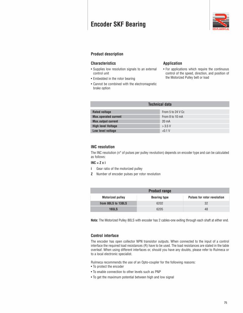
Characteristics• Supplies low resolution signals to an external
control unit• Embedded in the rotor bearing• Cannot be combined with the electromagnetic
brake option
Application• For applications which require the continuous
control of the speed, direction, and position ofthe Motorized Pulley belt or load
Product description
Technical data
From 5 to 24 V CcFrom 8 to 10 mA20 mA> 3.5 V<0.1 V
Rated voltageMax.operated currentMax.output currentHigh level VoltageLow level voltage
INC resolutionThe INC resolution (n° of pulses per pulley revolution) depends on encoder type and can be calculatedas follows:
INC = Z x i
i Gear ratio of the motorized pulleyZ Number of encoder pulses per rotor revolution
Motorized pulley
Product rangeBearing type
6202
6205
Pulses for rotor revolution
32
48
from 80LS to 138LS
165LS
Nota: The Motorized Pulley 80LS with encoder has 2 cables-one exiting through each shaft at either end.
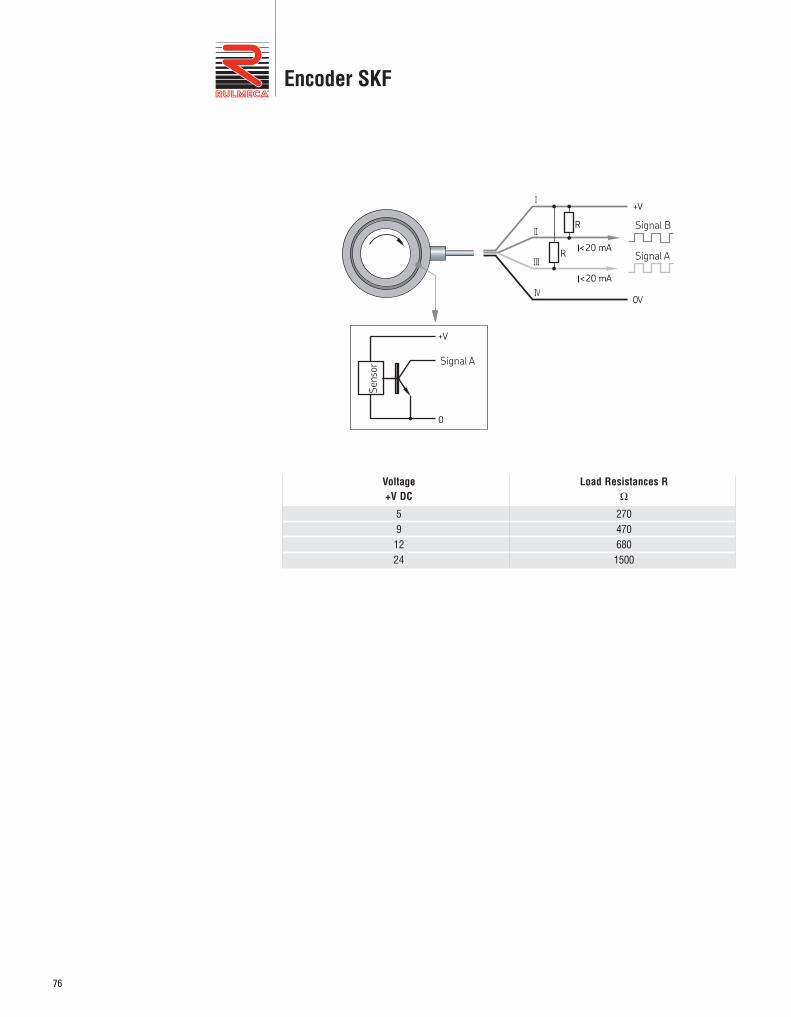
Control interfaceThe encoder has open collector NPN transistor outputs. When connected to the input of a controlinterface the required load resistances (R) have to be used. The load resistances are stated in the tableoverleaf. When using different interfaces or, should you have any doubts, please refer to Rulmeca orto a local electronic specialist.
Rulmeca recommends the use of an Opto-coupler for the following reasons:• To protect the encoder• To enable connection to other levels such as PNP• To get the maximum potential between high and low signal
Encoder SKF Bearing
76
Encoder SKF
2704706801500
591224
Voltage+V DC
Load Resistances RΩ
Encoder RLS
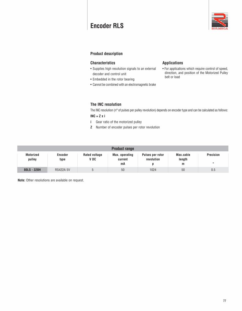
Characteristics • Supplies high resolution signals to an external
decoder and control unit• Embedded in the rotor bearing• Cannot be combined with an electromagnetic brake
Applications• For applications which require control of speed,
direction, and position of the Motorized Pulleybelt or load
Product description
The INC resolution The INC resolution (n° of pulses per pulley revolution) depends on encoder type and can be calculated as follows:
INC = Z x i
i Gear ratio of the motorized pulleyZ Number of encoder pulses per rotor revolution
Motorized pulley
Product range
80LS - 320H
Encoder type
RS422A 5V
Rated voltage V DC
5
Max. operatingcurrent
mA
50
Pulses per rotorrevolution
p
1024
Max.cable length
m
50
Precision
°
0.5
Note: Other resolutions are available on request.
77
78
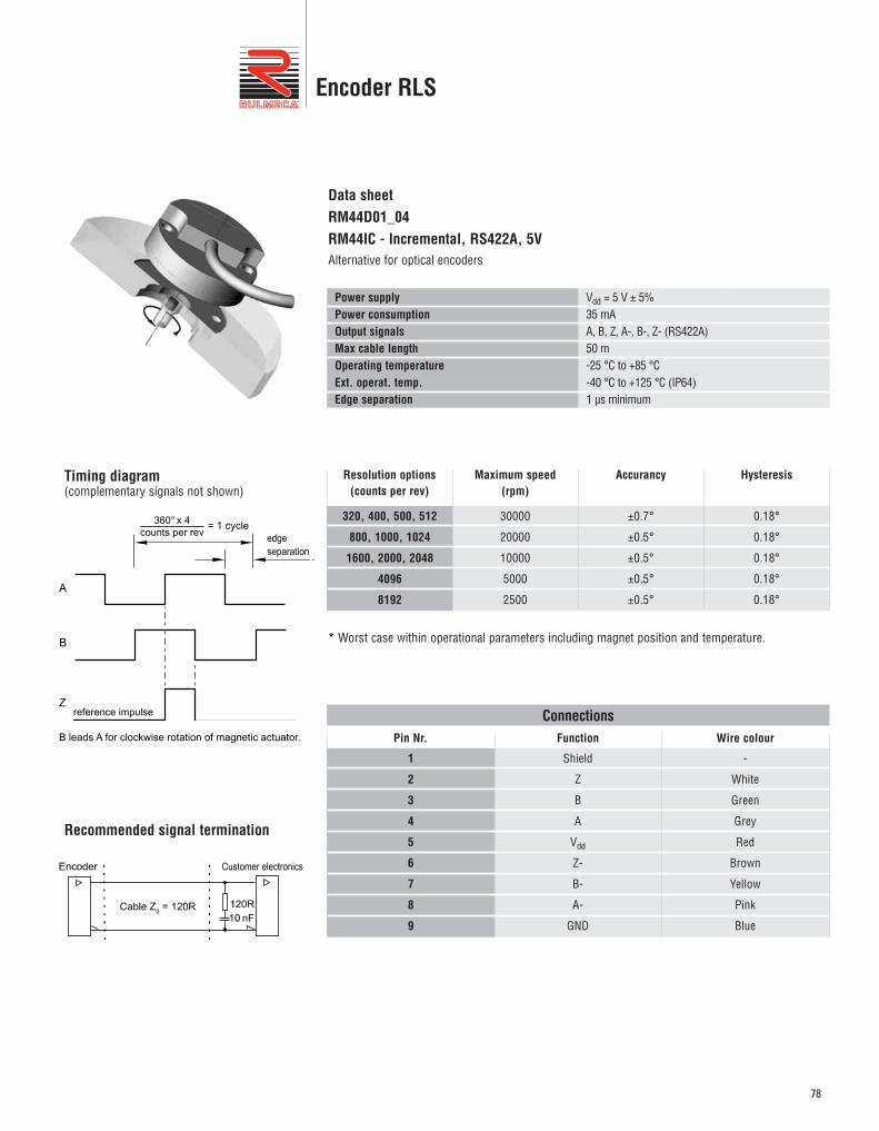
Data sheetRM44D01_04RM44IC - Incremental, RS422A, 5V Alternative for optical encoders
Vdd = 5 V ± 5%35 mAA, B, Z, A-, B-, Z- (RS422A)50 m-25 °C to +85 °C-40 °C to +125 °C (IP64)1 μs minimum
Power supplyPower consumptionOutput signalsMax cable lengthOperating temperatureExt. operat. temp.Edge separatio n
Pin Nr.
Connections
1
2
3
4
5
6
7
8
9
Function
Shield
Z
B
A
Vdd
Z-
B-
A-
GND
Wire colour
-
White
Green
Grey
Red
Brown
Yellow
Pink
Blue
Timing diagram(complementary signals not shown)
Recommended signal termination
Encoder RLS
Resolution options(counts per rev)
320, 400, 500, 512
800, 1000, 1024
1600, 2000, 2048
4096
8192
Maximum speed(rpm)
30000
20000
10000
5000
2500
Accurancy
±0.7°
±0.5°
±0.5°
±0.5°
±0.5°
Hysteresis
0.18°
0.18°
0.18°
0.18°
0.18°
* Worst case within operational parameters including magnet position and temperature.