Embed Size (px)
Citation preview
LACERTA M-GENStand-Alone AutoGuider
User’s manual for Firmware 02.10
Created by Zoltán ToblerLast updated: 16 May 2014
Table of contents
1 ABOUT THE HARDWARE ............................................................................................................................... 2
1.1 PARTS OF THE DEVICE .......................................................................................................................................... 2 1.2 POWERING THE DEVICE ......................................................................................................................................... 4 1.3 ELECTRICAL CHARACTERISTICS .............................................................................................................................. 5
1.3.1 Specification of the HC and Camera ...................................................................................................... 5 1.3.2 Imaging specification of the Camera ..................................................................................................... 6
1.4 TURNING ON AND OFF THE DEVICE ......................................................................................................................... 7 1.5 UPDATE MODE ................................................................................................................................................ 7 1.6 HARDWARE TYPES ............................................................................................................................................... 8
2 NEW FEATURES IN FW. 02.10 ........................................................................................................................ 9
2.1 PREVIOUS VERSION CHANGES ................................................................................................................................. 9
3 ABOUT THE USER INTERFACE .................................................................................................................. 15
3.1 BUTTONS AND LEDS ........................................................................................................................................ 15 3.2 MAIN CONCEPTION OF THE USER INTERFACE ......................................................................................................... 15
3.2.1 Menus ................................................................................................................................................... 16 3.2.2 Variables (parameters) ......................................................................................................................... 16 3.2.3 Profiles ................................................................................................................................................. 18
4 PARTS OF THE SOFTWARE, FUNCTIONAL UNITS ............................................................................... 19
4.1 AUTOGUIDING FUNCTION (AG) .......................................................................................................................... 19 4.2 AUTOEXPOSURE FUNCTION (AE) ........................................................................................................................ 20 4.3 RANDOM DISPLACEMENT FUNCTION (RD) ............................................................................................................ 20 4.4 FILESYSTEM (FS) ............................................................................................................................................. 21 4.5 COOPERATION OF THE FUNCTIONAL UNITS ............................................................................................................. 22
5 MENU TREE ...................................................................................................................................................... 23
5.1 SCREENS AND FUNCTIONS DETAILED ..................................................................................................................... 24 5.1.1 Autoexposure (AE) screen .................................................................................................................... 25 5.1.2 Autoexposure program list screen ....................................................................................................... 27 5.1.3 Random Displacement (RD) screen ..................................................................................................... 30 5.1.4 Misc. screen .......................................................................................................................................... 32 5.1.5 Power off screen ................................................................................................................................... 36 5.1.6 Guiding menu screen ............................................................................................................................ 37 5.1.7 Guider setup screen .............................................................................................................................. 38 5.1.8 Star Search screen ................................................................................................................................ 39 5.1.9 Live View screen ................................................................................................................................... 41 5.1.10 Guiding screen ................................................................................................................................... 43
6 MORE DETAILED ABOUT... ......................................................................................................................... 52
6.1 ... CCD BINNING .............................................................................................................................................. 52 6.2 ... THE NEW IMAGE PROCESSING METHOD ............................................................................................................ 53
7 PLANNED DEVELOPMENTS ........................................................................................................................ 54
1
1 About the Hardware
1.1 Parts of the device
The “LACERTA M-GEN Stand-Alone AutoGuider” (referenced as LMG) consists of the following parts:
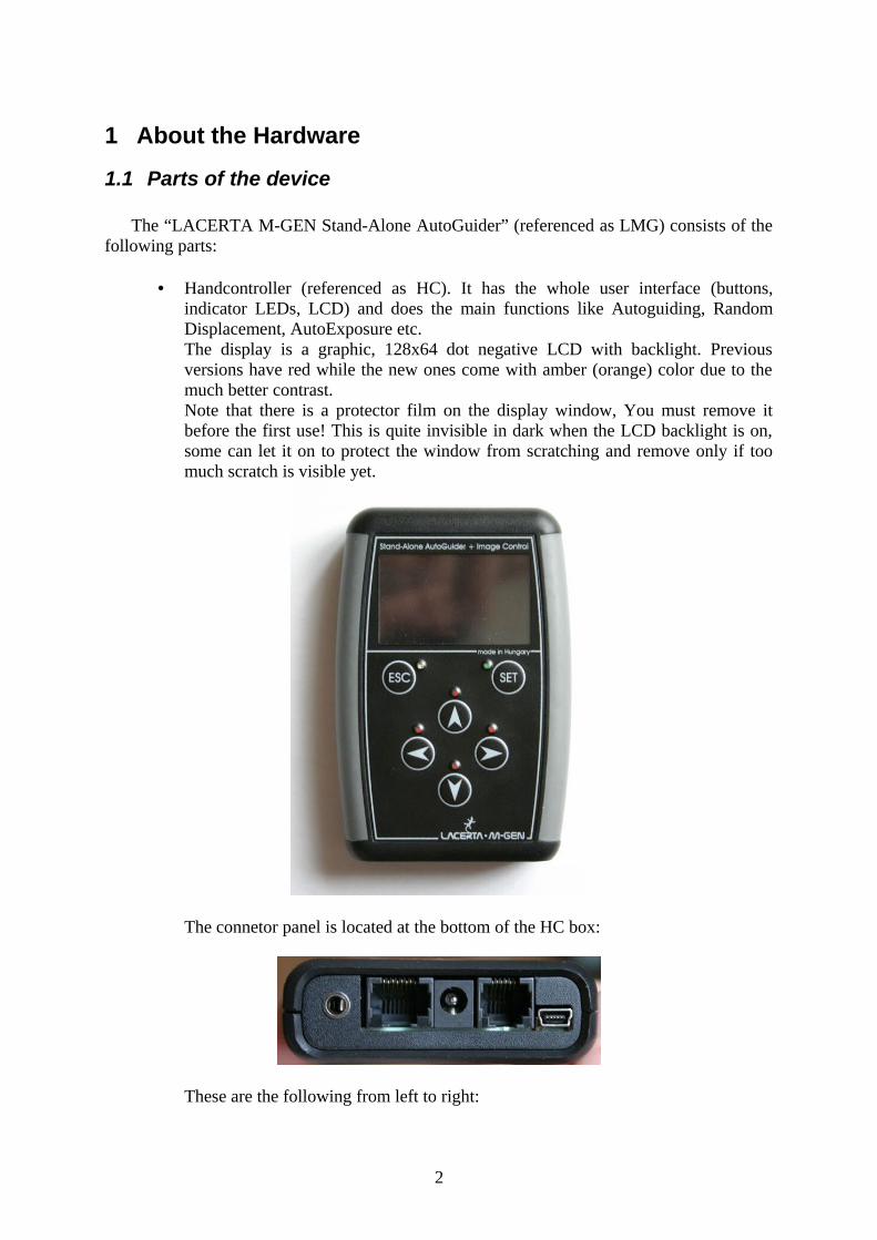
• Handcontroller (referenced as HC). It has the whole user interface (buttons, indicator LEDs, LCD) and does the main functions like Autoguiding, Random Displacement, AutoExposure etc.The display is a graphic, 128x64 dot negative LCD with backlight. Previous versions have red while the new ones come with amber (orange) color due to the much better contrast. Note that there is a protector film on the display window, You must remove it before the first use! This is quite invisible in dark when the LCD backlight is on, some can let it on to protect the window from scratching and remove only if too much scratch is visible yet.
The connetor panel is located at the bottom of the HC box:
These are the following from left to right:
2
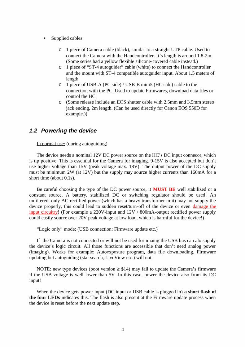
o Canon EOS compatible shutter output (3.5mm stereo jack conn.)o Camera port (RJ-45 type female conn., can be used any (max. 2m) UTP
cable too but the supplied cable is preferred. Note: NEVER try to use a UTP cross cable!)
o DC power input (5.5/2.1mm size) (12V nominal, 9-15V), tip positive (polarity-protected)
o ST-4 compatible autoguider output (RJ-12 type female conn.)o PC communication port (USB-B mini 5-pin conn.)
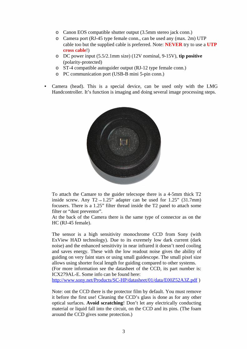
• Camera (head). This is a special device, can be used only with the LMG Handcontroller. It’s function is imaging and doing several image processing steps.
To attach the Camare to the guider telecsope there is a 4-5mm thick T2 inside screw. Any T2→1.25” adapter can be used for 1.25” (31.7mm) focusers. There is a 1.25” filter thread inside the T2 panel to attach some filter or “dust preventor”.At the back of the Camera there is the same type of connector as on the HC (RJ-45 female).
The sensor is a high sensitivity monochrome CCD from Sony (with ExView HAD technology). Due to its exremely low dark current (dark noise) and the enhanced sensitivity in near infrared it doesn’t need cooling and saves energy. These with the low readout noise gives the ability of guiding on very faint stars or using small guidescope. The small pixel size allows using shorter focal length for guiding compared to other systems.(For more information see the datasheet of the CCD, its part number is: ICX279AL-E. Some info can be found here:http://www.sony.net/Products/SC-HP/datasheet/01/data/E00Z52A3Z.pdf )
Note: ont the CCD there is the protector film by default. You must remove it before the first use! Cleaning the CCD’s glass is done as for any other optical surfaces. Avoid scratching! Don’t let any electrically conducting material or liquid fall into the circuit, on the CCD and its pins. (The foam around the CCD gives some protection.)
3
• Supplied cables:
o 1 piece of Camera cable (black), similar to a straight UTP cable. Used to connect the Camera with the Handcontroller. It’s length is around 1.8-2m.(Some series had a yellow flexible silicone-covered cable instead.)
o 1 piece of “ST-4 autoguider” cable (white) to connect the Handcontroller and the mount with ST-4 compatible autoguider input. About 1.5 meters of length.
o 1 piece of USB-A (PC side) / USB-B mini5 (HC side) cable to the connection with the PC. Used to update Firmwares, download data files or control the HC.
o (Some release include an EOS shutter cable with 2.5mm and 3.5mm stereo jack ending, 2m length. (Can be used directly for Canon EOS 550D for example.))
1.2 Powering the device
In normal use: (during autoguiding)
The device needs a nominal 12V DC power source on the HC’s DC input connecor, which is tip positive. This is essential for the Camera for imaging. 9-15V is also accepted but don’t use higher voltage than 15V (peak voltage max. 18V)! The output power of the DC supply must be minimum 2W (at 12V) but the supply may source higher currents than 160mA for a short time (about 0.1s).
Be careful choosing the type of the DC power source, it MUST BE well stabilized or a constant source. A battery, stabilized DC or switching regulator should be used! An unfiltered, only AC-rectified power (which has a heavy transformer in it) may not supply the device properly, this could lead to sudden reset/turn-off of the device or even damage the input circuitry! (For example a 220V-input and 12V / 800mA-output rectified power supply could easily source over 20V peak voltage at low load, which is harmful for the device!)
“Logic only” mode: (USB connection: Firmware update etc.)
If the Camera is not connected or will not be used for imaing the USB bus can alo supply the device’s logic circuit. All those functions are accessible that don’t need analog power (imaging). Works for example: Autoexposure program, data file downloading, Firmware updating but autoguiding (star search, LiveView etc.) will not.
NOTE: new type devices (boot version ≥ $14) may fail to update the Camera’s firmware if the USB voltage is well lower than 5V. In this case, power the device also from its DC input!
When the device gets power input (DC input or USB cable is plugged in) a short flash of the four LEDs indicates this. The flash is also present at the Firmware update process when the device is reset before the next update step.
4
1.3 Electrical characteristics
1.3.1 Specification of the HC and Camera
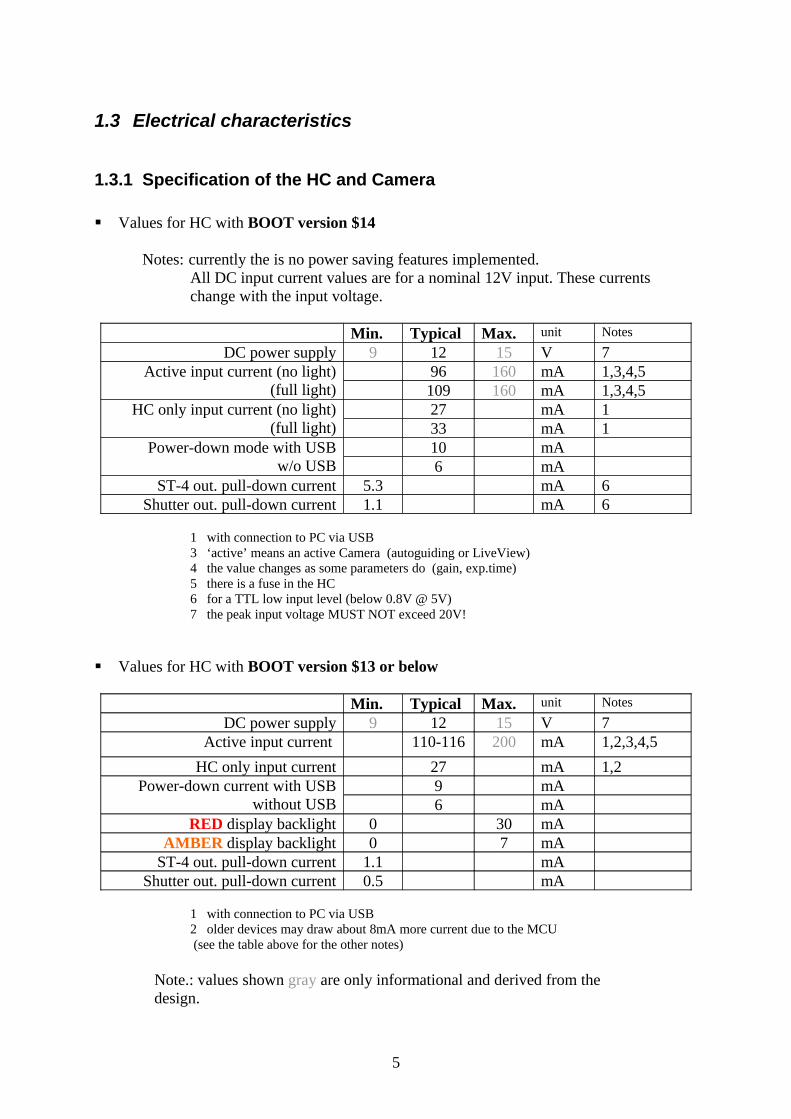
Values for HC with BOOT version $14
Notes: currently the is no power saving features implemented.All DC input current values are for a nominal 12V input. These currents change with the input voltage.
Min. Typical Max. unit Notes
DC power supply 9 12 15 V 7Active input current (no light)
(full light)96 160 mA 1,3,4,5109 160 mA 1,3,4,5
HC only input current (no light)(full light)
27 mA 133 mA 1
Power-down mode with USBw/o USB
10 mA6 mA
ST-4 out. pull-down current 5.3 mA 6Shutter out. pull-down current 1.1 mA 6
1 with connection to PC via USB3 ‘active’ means an active Camera (autoguiding or LiveView)4 the value changes as some parameters do (gain, exp.time)5 there is a fuse in the HC6 for a TTL low input level (below 0.8V @ 5V)7 the peak input voltage MUST NOT exceed 20V!
Values for HC with BOOT version $13 or below
Min. Typical Max. unit Notes
DC power supply 9 12 15 V 7Active input current 110-116 200 mA 1,2,3,4,5
HC only input current 27 mA 1,2Power-down current with USB
without USB9 mA6 mA
RED display backlight 0 30 mAAMBER display backlight 0 7 mA
ST-4 out. pull-down current 1.1 mAShutter out. pull-down current 0.5 mA
1 with connection to PC via USB2 older devices may draw about 8mA more current due to the MCU (see the table above for the other notes)
Note.: values shown gray are only informational and derived from the design.
5
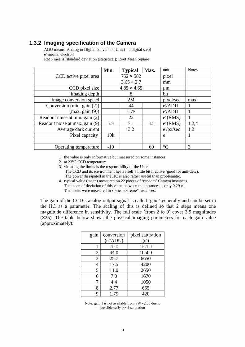
1.3.2 Imaging specification of the CameraADU means: Analog to Digital conversion Unit (= a digital step)e- means: electronRMS means: standard deviation (statistical); Root Mean Square
Min. Typical Max. unit Notes
CCD active pixel area 752 × 582 pixel3.65 × 2.7 mm
CCD pixel size 4.85 × 4.65 μmImaging depth 8 bit
Image conversion speed 2M pixel/sec max.Conversion (min. gain (2))
(max. gain (9))44 e-/ADU 1
1.75 e-/ADU 1Readout noise at min. gain (2) 22 e- (RMS) 1Readout noise at max. gain (9) 5.9 7.1 8.5 e- (RMS) 1,2,4
Average dark current 3.2 e-/px/sec 1,2Pixel capacity 10k e- 1
Operating temperature -10 60 °C 3
1 the value is only informative but measured on some instances2 at 23ºC CCD temperature3 violating the limits is the responsibility of the User The CCD and its environment heats itself a little bit if active (good for anti-dew). The power dissapated in the HC is also rather useful than problematic.4 typical value (mean) measured on 22 pieces of ‘random’ Camera instances. The mean of deviation of this value between the instances is only 0.29 e-. The limits were measured in some “extreme” instances.
The gain of the CCD’s analog output signal is called ‘gain’ generally and can be set in the HC as a parameter. The scaling of this is defined so that 2 steps means one magnitude difference in sensitivity. The full scale (from 2 to 9) cover 3.5 magnitudes (×25). The table below shows the physical imaging parameters for each gain value (approximately):
gain conversion(e-/ADU)
pixel saturation(e-)
1 70.0 167002 44.0 105003 25.7 66504 17.5 42005 11.0 26506 7.0 16707 4.4 10508 2.77 6659 1.75 420
Note: gain 1 is not available from FW v2.00 due topossible early pixel-saturation
6
1.4 Turning on and off the device
After the device is first supplied with power source it goes to sleep (power-down) mode, nothing can be seen and there are no output signals. The cables can be safely plugged in or out.
Turning ON the device:
Press ESC button! The program will start in application mode if the HC contains valid Firmware. The version of it is displayed for 2 seconds, then the first screen appears (see later). You can skip 2 sec. waiting with pressing ESC one more.
If the device does not contain valid Firmware (or it was faulty) it starts in update mode, which is shown on the LCD. In the center of the display there is a “NO FIRMWARE” text indicating the case.
If ESC is pressed continuously for more than 1 second the device starts in update mode (Error: Reference source not found). Using this starting procedure is not required because the updater (PC application) will force to restart the device in this mode. If You happen to enter this mode, hold down SET for 1 second and the Firmware will try to start. This works until the device communicates through USB, after this only an USB command can start the firmware (using PC application).
From Firmware ver. 1.21 (or later) the device starts on the date and time settings screen and the filesystem’s screen after that. This is needed to make You remember to set or check the correct date and time at every startup and select a file to open if You want to store data about the night (guiding, events etc.). If You don’t need these functions, two more ESC keypresses after startup leads directly to the main menu.
Turning OFF the device:
In application mode: Navigate back to the main menu (with pressing ESC some times) and select the power off item. It is essential to power off this way because it stops every functional part properly (Camera), closes the open file and stores the parameter settings.
WARNING: simply plugging out the power cable is not recommended, mainly if the Camera is actively working! Data loss or corruption in the open file or in the stored parameters may occur.
If the device is in update mode and there is no operation in progress (mainly Firmware update), You can power-off the device with detaching the power cable(s). (Be sure there is no operation in progress shown by the PC application.)
WARNING: never plug out the power/USB cable during Firmware update! Doing so can damage the boot program and it may be required to reconfigure the device at factory (it’s not the part of warranty).
1.5 UPDATE mode
Also known as BOOT mode. The device always starts in BOOT mode by pressing ESC, but doesn’t start the firmware if You hold ESC button for more than 1 second. If there is no
7
valid firmware on the device, UPDATE mode will start anyway with the text ‘NO FIRMWARE’.
This mode is used to update the Firmware or download/refresh stored parameter data. The PC application may make the running Firmware to enter this mode (even during autoguiding), be careful! More on this at Error: Reference source not found or in the PC app.’s manual.
1.6 Hardware types
There are two types of hardware of this device (HandController and Camera). The newer will show a little X right to the ‘UPDATE MODE’ text to indicate the new hardware type. Besides the HC will show a BOOT version of $14 and the Camera BOOT version of $14 as well. (See PC app.’s manual how to check this.) Lower BOOT versions indicate ‘old’ hardware.
Note that the new hardware can not run Firmware version older than 2.00 due to the hardware change. Uploading such an old firmware will succeed but the HandController will display ‘WRONG FIRMWARE’ in update mode.
The difference between the two hardvare types are the following:• the new can be turned on by remote (USB) while the old can not;• the new can be used with a (supplied) 6-wire cable while the old works only with a
8-wire one;• the new can’t run a Firmware below 2.00;• the new contains a small beeper built-in (though not activated yet).
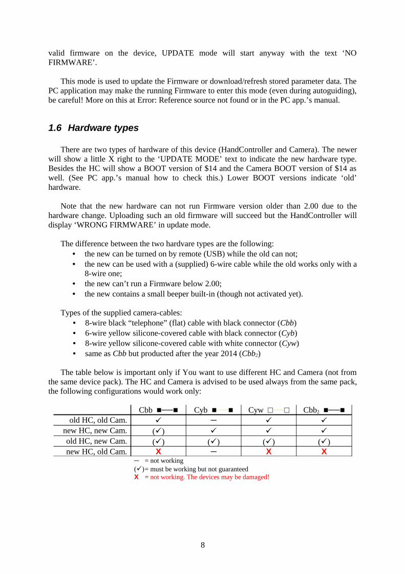
Types of the supplied camera-cables:• 8-wire black “telephone” (flat) cable with black connector (Cbb)• 6-wire yellow silicone-covered cable with black connector (Cyb)• 8-wire yellow silicone-covered cable with white connector (Cyw)• same as Cbb but producted after the year 2014 (Cbb2)
The table below is important only if You want to use different HC and Camera (not from the same device pack). The HC and Camera is advised to be used always from the same pack, the following configurations would work only:
Cbb ■──■ Cyb ■──■ Cyw □──□ Cbb2 ■──■old HC, old Cam. ─
new HC, new Cam. () old HC, new Cam. () () () ()new HC, old Cam. X ─ X X
─ = not working()= must be working but not guaranteedX = not working. The devices may be damaged!
8
2 New features in Fw. 02.10
o New (optional) star position determining algorithm. Less absolute position noise, no threshold required, auto “partial” feature for high separation doublets and more tolerance to hard-separable doublets.FWHM is also available for each frame (with a good approximation).
o Firmware is ready for languages other than english.
o “Manual AG” output control now works with PC App. v2.10.
o DEC axis can be disabled for guiding (with Num=0, see 5.1.10.3 ). Calibration works for RA only too.
o LiveView frames are enhanced.
o Fixed bugs:
2x2 binned hot pixel cosmetics works now as it should.
Random software reset bug fixed when Camera got inaccessible at LiveView.
LiveView shows “white” when the frame is saturated. (Not probably case at night...)
2.1 Previous version changes
From 02.04:
o Hot pixel map handling of Camera. These pixels are cosmetized while autoguiding or searching stars. Available only for 1x1 and 2x2 binning modes.
o Support for Astro Photography Tool (© Incanus Ltd.). Dithering by M-Gen and exposures by APT could be synchronized.
o Fixed bugs:
USB interface is reset when the cable is plugged out, to recover from a wrong communication without a power-off reset.
4th exposure slot data were not stored into EEPROM memory.
Internal fixes, affecting UI and control performance.
9
From 02.03:
o AutoExposure is expanded to 4 program slots and different program modes. Read more on this at 5.1.2
o Increased frequency against low-light blinking of LEDs.
o Fixed bugs:
Calendar changed to the 1st of January of next year after 30th of November 23:59:59.
From 02.02:
o Direct switching between Guiding and AutoExposure screens using ESC held down for more than half second.
o Internal fixes.
o PC application changed, has a graphical user interface (Windows op. systems).
From 02.01:
o An “idle LED light” can be set to help finding the buttons in the dark.
o When starting the autoguiding, parameters is stored to file like camera gain, expo time, threshold and the RA’s and DEC’s current autoguide settings (page 3,4 of the guiding screen).
o Absolute star position (CCD coordinates) can be saved to file with manual start/stop when autoguiding is not in progress. The data could be used to check Periodic Error of the mount etc.
o A new star-image processing function is available, called ‘partial search’. This helps to separate double stars appearing in the guiding window and only one of those will be used and followed for guiding. (The problem occurs mostly when using short focal length guiding scope.)
o The latest star position is displayed with some pixels at the guiding window’s edges. Helps to find out where the guider thinks the star’s center is. (The ‘partial’ image processing mode mostly requires this.)
From 02.00:
A short list about the main features compared to the pre-release (01.99):
o It can handle the device with new hardware. (The new hardware is indicated by the BOOT version number which is $14 instead of $13.)
10
o Star search function is bugfixed and works for all the binning modes, after changing the binning and the ‘last results’ do also.
o New LiveView mode: pixel averaging with maximum removal (also called as hot pixel rejection mode average / ‘havg’). Useful to virtually remove disturbing hot pixels but to hold faint stars on the screen.
o Fixed bugs:
Star search data: the selected star’s brightness is displayed right in summed ADU units (approximately, precision depends on many things).
LiveView’s exposure compensation is now good for all the binning modes.
When the guiding window changed its position, the pos.limit and inhibit time (0.5 sec) was wrong.
A short list about the main features of the pre-release (1.99) compared to the previous one (01.22):
o Hardware binning operation modes implemented into the Camera.
o Automatic continuation of following the star (in the old position) after a LiveView usage (without setting a new guiding position) when re-entering the guiding screen.
o More fine ‘LiveView dark compensation’. (Keeps the image vertically ‘flat’.)
o Better CCD interlaced readout technique for more precise guiding frames.
o ‘Camera OFF’ is displayed wherever is necessary.
o 5th page (“extra”) is introduced for the guiding screen(s) (‘Guiding / Current guiding’). The changes are:
Camera can be turned ON and OFF manually on this page. The position of the guiding window is memorized except between binning changes.
The ‘wait’ time variable is moved to page 5. (Most of the users don’t need this at page 1.)
o The guiding window display mode can be changed now from all the pages.
o The guiding window display mode ‘maxY’ is renamed to ‘profile’ as the image shown is the guiding image’s (vertical) profile. This is NOT a histogram.
o The used threshold level is shown as an inverted horizontal line at the ‘profile’ display mode. (See above.)
11
o The ‘drifts’ display mode uses ± 4 LCD pixels as the tolerance interval. If the drift exceeds the display area (± 12 pixels for each axis) it means that drift reached the ‘emergency interval’, which is 3 times the tolerance interval.
o Guiding window is locked at guiding, otherwhise it follows the star.
o Text (detailed) error display. (Except some rare cases.)
From 01.22:
o The AutoExposure’s state and outputs are also stored into the open file. The guiding curve (“drifts”) is saved only when the AE is in the exposure state.
It belongs that the PC application version 1.22 generates a HTML format output when downloading a file, which contains for all the exposures separately the guiding curve as well as the spread of the guiding star positions and the approximated tracking error of the mount (derived from the autoguider signals).All the raw data is written into a CSV file for any user processing.
o The calibration has been moved to a new screen, on which the directions, speeds and the orthogonality is displayed.
o When starting the autoguiding the latest position is not rounded to pixel center but used the raw position directly for the new guiding center.
From 01.21:
o The menu structure has been changed a little bit. Some rarely used screen and parameter is pushed “down the tree” while (for example) the guiding screen is now accessible with only two SET keypresses from the main menu.
o Complete file(system) menu screens: open, close, delete and create new, a short file list and file details screen. The date and time settings screen is also accessible now from menu.
o In Autoexposure, selecting Start/Stop, Pause will change the selection to the more understandable item.
o LCD contrast can be set (and is stored).
o “AstroTimer mode”: the Autoexposure’s and Random Displacement’s opertion mode using an external shutter controller device. (This mode is fully compatible with AstroTimer.) The Autoexposure will have only one time value (period) to set while the external shutter is active and the shutter output will be only active when a Random Displacement is being made (the AE program is in wait state).
o New RD mode: besides the default “uniform square” there is a new “square snake” pattern.
12
o Exclusive autoguiding output signalling mode. (“Non-simultaneous signalling”). Only one axis can have autoguiding signal active at a time, that’s why it is called “exclusive mode”. Between different axis’ signal there is a 62ms dead time. This may be used with “old, touchy“ mount that don’t tolerate the default parallel signalling.
o Bugfix : quitting from LiveView screen did not stop the imaging into the screen.
o Bugfix : in some special cases the “guiding image” was drawn into false position – even if it was inactive.
From 01.20:
o Stepping back in menu tree will hold the priously selected item. It’s easier to re-enter a screen if You had left it accidentally.
o The method of calibration is modified: now it’s more immune to temporary star lose, position evaluation bettered and the result’s precision (axis direction) is displayed.
o Modified RD method: it does not move the guide star to an exact position, instead it moves it only “close to it” to minimize the dead time between the exposures (that was rather long in wind or at bad seeing/parametrization).
o Real-time clock (0.1s resolution) and date to timestamp the data stored in the open file.
o Basic filesystem (and selection only at startup). The open file will store the guiding “drifts” and the calculated autoguider output signal lengths. To download the files use the PC application v1.22.
o Bugifx : some more-byte parameters were not stored correctly at power-off.
From 01.12:
o Three profiles available now to store parameter settings individually. Can be used as “presets” for separate guiding configuration (off-axis, guide scope(s) etc.);
o AG speed can be set independent for each axis with 0.01 step size (any non-standard correction speed can be set);
o The “drifts” history diagram is now displayed scaled to the tolerance value;o Pause/Continue button added to the AutoExposure screen – during paused state the
AE program parameters can be changed;o Additional wait time can be set between the guiding exposures letting the mount to
react before the next exposure. (Useful to lower the chance for oscillation.) – will be obsolete, using the smart guiding method implemented soon.
From 01.11:
13

o New “drifts” as a guiding display mode: the history of the drifts of the guiding star can be monitored for the previous 48 frames;
o Increased LCD backlight PWM frequency, it has no effect on the Camera now (in LiveView had a tiny);
o Bugfix: “Camera stop in cold” symptom has been corrected (in hardware too).
From 01.10:
o LiveView function (1:10 size real time image for the entire CCD field);o The “threshold” parameter is now set in pecentage;o Some parameters can be changed with LEFT or RIGHT buttons too;o Advanced method for StarSearch – overexposed stars are missed more rarely;o The brightness of indicator LEDs can be set individually;o Asking for stopping the guiding if it’s in progress and some function needs to have
it stopped;o Autorepeat for all the buttons – makes the navigation or parameter change easier;o A 0.5s dead time for the buttons is inserted at the power off screen to avoid
accidental power-off of the device.
From 01.09 and before:
o Adoptation from the prototype circuit and software, hardware changes.o Indicator LEDs are now active;o Bugfix : AutoExposure did short “wake-up” signals periodically in wait state;o ...and much more tiny changes...
14
3 About the user interface
3.1 Buttons and LEDs
On the front panel of the HC there are 6 buttons and 6 so-called indicator LEDs next to them. The buttons are for navigation and controlling of the device while the LEDs indicates some action of it for visual checking.
These are the following:
o ESC Functions: back, cancel or exit.Main function: exiting from the current screen.blue LED indicator: shutter focus line active - feedback (default).
o SET Functions: enter (into sub-menu), choose, set, activate, start editing.Main function: activating the selected item on the screen.green LED indicator: shutter exposure line active – feedback (default).
o UP, DOWN (arrows)Functions: select prev./next item, inc./dec. digit (in editing mode), DEC manual guiding.Main function: navigation between the screen’s items.red LED indicators: DEC axis correction output line(s) active. (Shows what is physically on the autoguider output).
o LEFT, RIGHT (arrows)Functions: changing the value of the selected item, (select prev./next item,) moving the cursor (in editing mode), RA manual guiding.red LED indicators: RA axis correction output line(s) active. (Shows what is physically on the autoguider output).
3.2 Main conception of the User Interface
The display and controlling of the device is menu-based. By default there is always an active screen, holding one selected item on it (for most of the screens). The selected item is always shown inverse. (This is something like a cursor for the actual screen items.) The selected item can be activated by pressing the SET button. Activating means entering to editing mode (to change its value) or doing some function. By default You can change the selected item (~”move the cursor”) with UP and DOWN buttons and in some cases LEFT and RIGHT could also be used.
This “screenshot” below shows the main menu with the “Exposure” item selected on it:
15
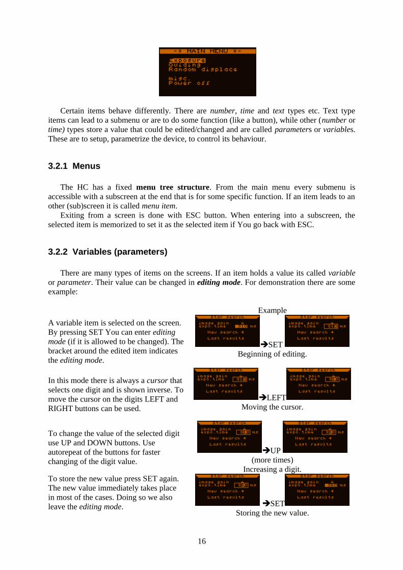
Certain items behave differently. There are number, time and text types etc. Text type items can lead to a submenu or are to do some function (like a button), while other (number or time) types store a value that could be edited/changed and are called parameters or variables. These are to setup, parametrize the device, to control its behaviour.
3.2.1 Menus
The HC has a fixed menu tree structure. From the main menu every submenu is accessible with a subscreen at the end that is for some specific function. If an item leads to an other (sub)screen it is called menu item.
Exiting from a screen is done with ESC button. When entering into a subscreen, the selected item is memorized to set it as the selected item if You go back with ESC.
3.2.2 Variables (parameters)
There are many types of items on the screens. If an item holds a value its called variable or parameter. Their value can be changed in editing mode. For demonstration there are some example:
Example
A variable item is selected on the screen. By pressing SET You can enter editing mode (if it is allowed to be changed). The bracket around the edited item indicates the editing mode.
SET Beginning of editing.
In this mode there is always a cursor that selects one digit and is shown inverse. To move the cursor on the digits LEFT and RIGHT buttons can be used.
LEFTMoving the cursor.
To change the value of the selected digit use UP and DOWN buttons. Use autorepeat of the buttons for faster changing of the digit value.
UP (more times)
Increasing a digit.To store the new value press SET again. The new value immediately takes place in most of the cases. Doing so we also leave the editing mode. SET
Storing the new value.
16
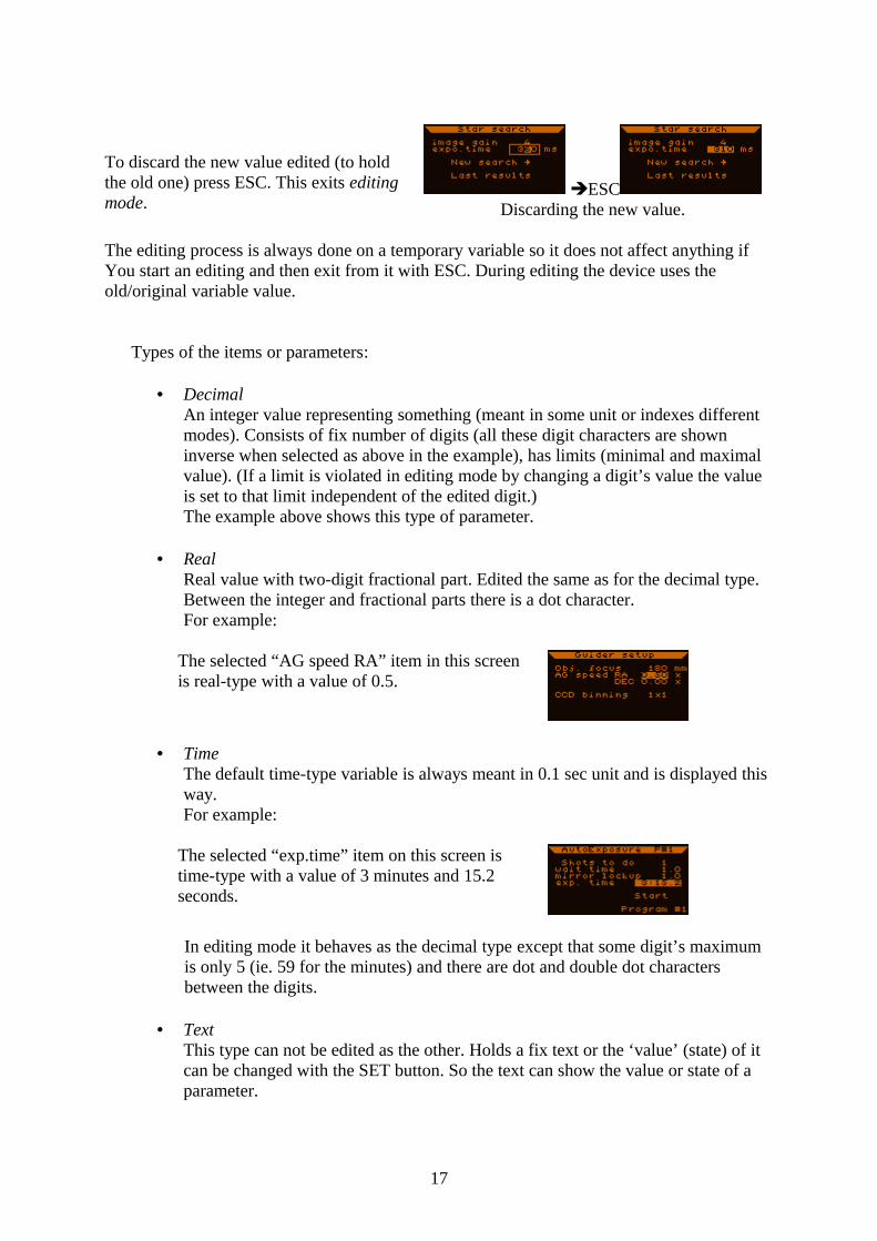
To discard the new value edited (to hold the old one) press ESC. This exits editing mode.
ESCDiscarding the new value.
The editing process is always done on a temporary variable so it does not affect anything if You start an editing and then exit from it with ESC. During editing the device uses the old/original variable value.
Types of the items or parameters:
• DecimalAn integer value representing something (meant in some unit or indexes different modes). Consists of fix number of digits (all these digit characters are shown inverse when selected as above in the example), has limits (minimal and maximal value). (If a limit is violated in editing mode by changing a digit’s value the value is set to that limit independent of the edited digit.)The example above shows this type of parameter.
• RealReal value with two-digit fractional part. Edited the same as for the decimal type. Between the integer and fractional parts there is a dot character.For example:
The selected “AG speed RA” item in this screen is real-type with a value of 0.5.
• TimeThe default time-type variable is always meant in 0.1 sec unit and is displayed this way.For example:
The selected “exp.time” item on this screen is time-type with a value of 3 minutes and 15.2 seconds.
In editing mode it behaves as the decimal type except that some digit’s maximum is only 5 (ie. 59 for the minutes) and there are dot and double dot characters between the digits.
• TextThis type can not be edited as the other. Holds a fix text or the ‘value’ (state) of it can be changed with the SET button. So the text can show the value or state of a parameter.
17
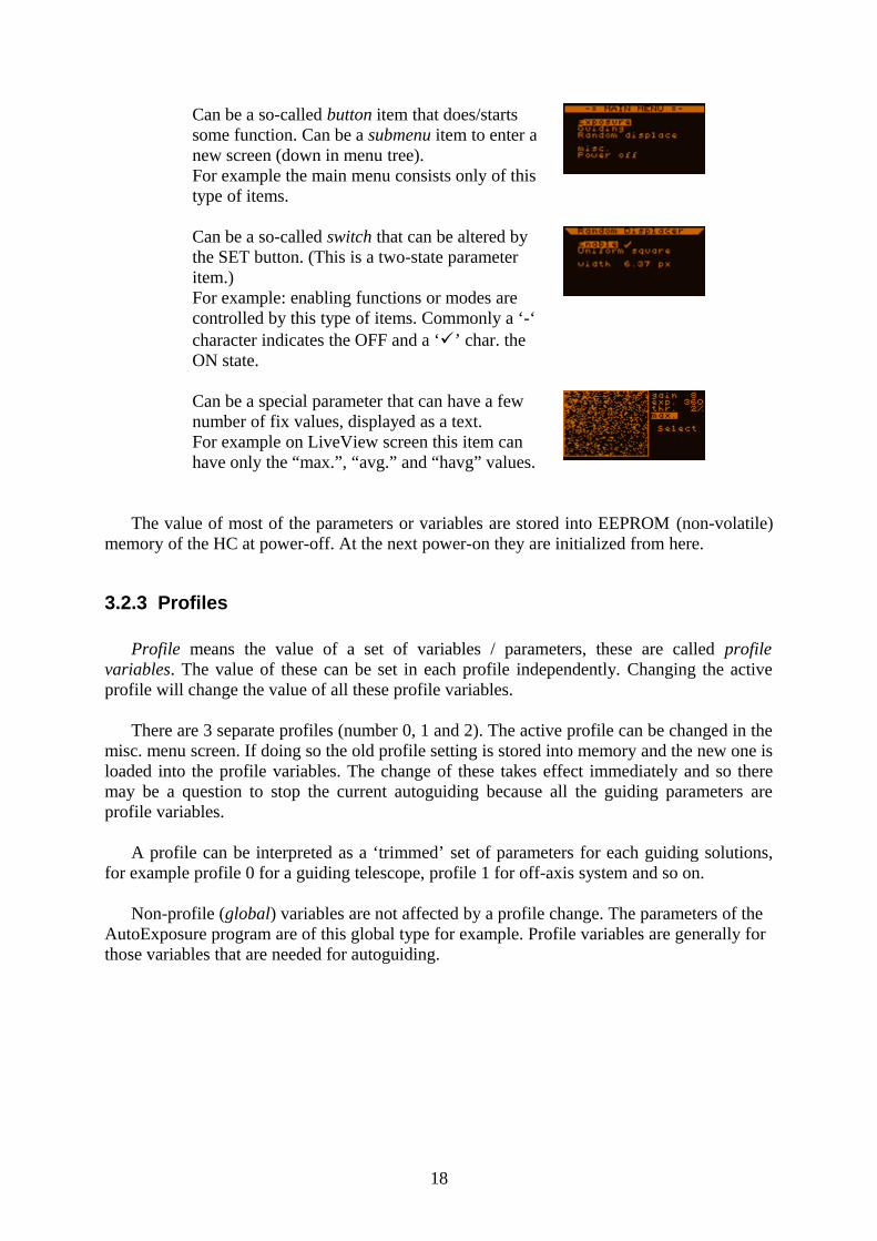
Can be a so-called button item that does/starts some function. Can be a submenu item to enter a new screen (down in menu tree).For example the main menu consists only of this type of items.
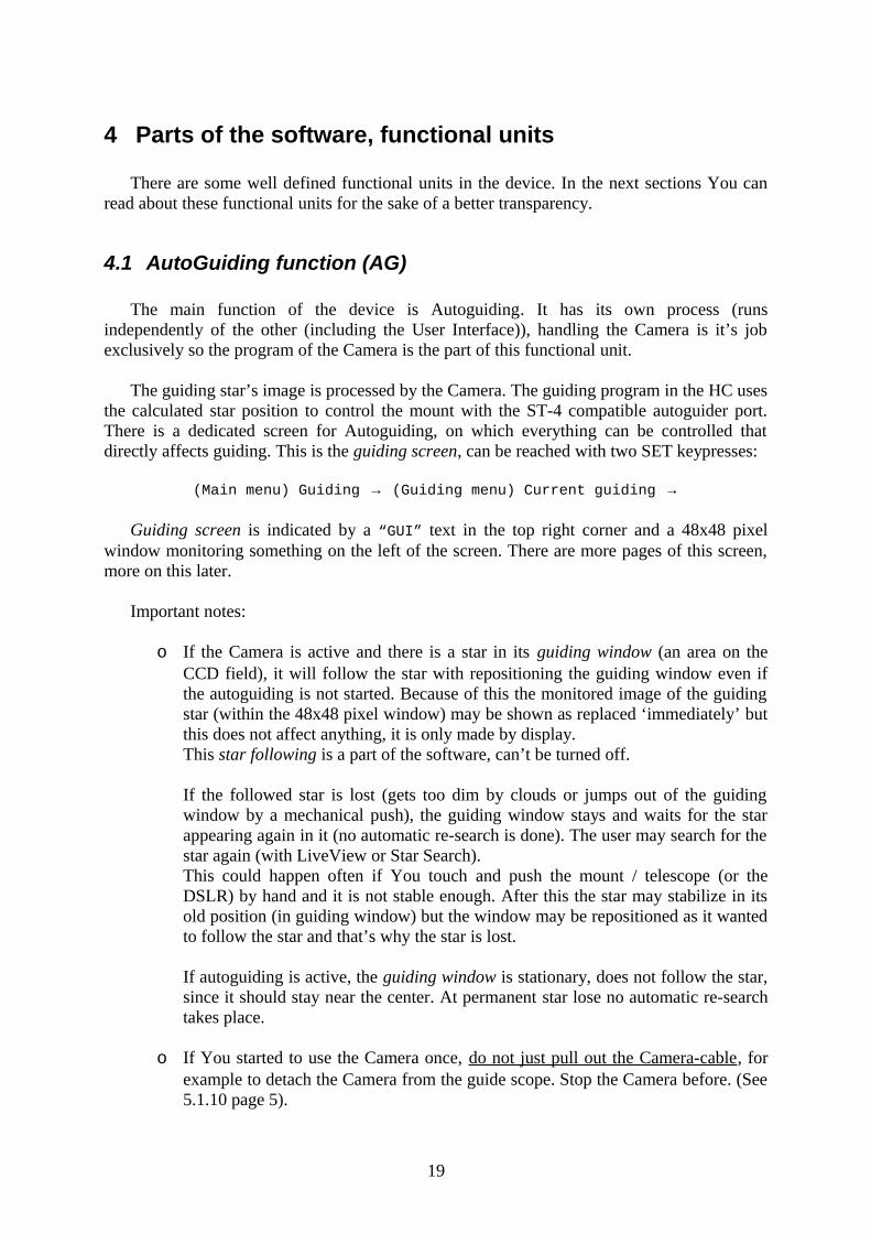
Can be a so-called switch that can be altered by the SET button. (This is a two-state parameter item.)For example: enabling functions or modes are controlled by this type of items. Commonly a ‘-‘ character indicates the OFF and a ‘’ char. the ON state.
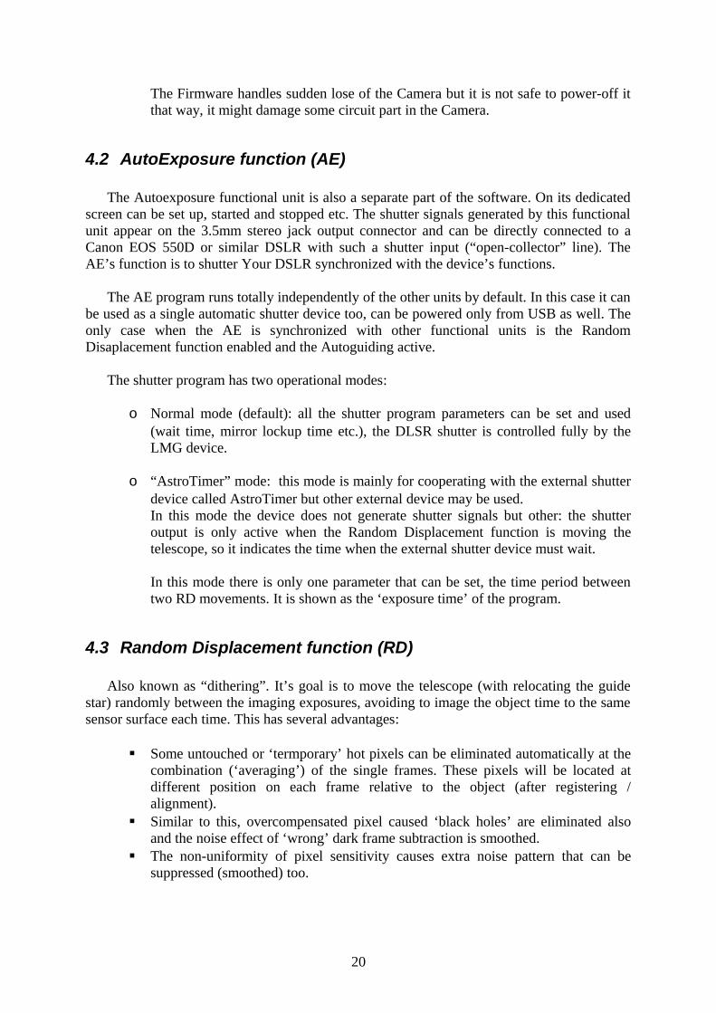
Can be a special parameter that can have a few number of fix values, displayed as a text.For example on LiveView screen this item can have only the “max.”, “avg.” and “havg” values.
The value of most of the parameters or variables are stored into EEPROM (non-volatile) memory of the HC at power-off. At the next power-on they are initialized from here.
3.2.3 Profiles
Profile means the value of a set of variables / parameters, these are called profile variables. The value of these can be set in each profile independently. Changing the active profile will change the value of all these profile variables.
There are 3 separate profiles (number 0, 1 and 2). The active profile can be changed in the misc. menu screen. If doing so the old profile setting is stored into memory and the new one is loaded into the profile variables. The change of these takes effect immediately and so there may be a question to stop the current autoguiding because all the guiding parameters are profile variables.
A profile can be interpreted as a ‘trimmed’ set of parameters for each guiding solutions, for example profile 0 for a guiding telescope, profile 1 for off-axis system and so on.
Non-profile (global) variables are not affected by a profile change. The parameters of the AutoExposure program are of this global type for example. Profile variables are generally for those variables that are needed for autoguiding.
18
4 Parts of the software, functional units
There are some well defined functional units in the device. In the next sections You can read about these functional units for the sake of a better transparency.
4.1 AutoGuiding function (AG)
The main function of the device is Autoguiding. It has its own process (runs independently of the other (including the User Interface)), handling the Camera is it’s job exclusively so the program of the Camera is the part of this functional unit.
The guiding star’s image is processed by the Camera. The guiding program in the HC uses the calculated star position to control the mount with the ST-4 compatible autoguider port. There is a dedicated screen for Autoguiding, on which everything can be controlled that directly affects guiding. This is the guiding screen, can be reached with two SET keypresses:
(Main menu) Guiding → (Guiding menu) Current guiding →
Guiding screen is indicated by a “GUI” text in the top right corner and a 48x48 pixel window monitoring something on the left of the screen. There are more pages of this screen, more on this later.
Important notes:
o If the Camera is active and there is a star in its guiding window (an area on the CCD field), it will follow the star with repositioning the guiding window even if the autoguiding is not started. Because of this the monitored image of the guiding star (within the 48x48 pixel window) may be shown as replaced ‘immediately’ but this does not affect anything, it is only made by display.This star following is a part of the software, can’t be turned off.
If the followed star is lost (gets too dim by clouds or jumps out of the guiding window by a mechanical push), the guiding window stays and waits for the star appearing again in it (no automatic re-search is done). The user may search for the star again (with LiveView or Star Search).This could happen often if You touch and push the mount / telescope (or the DSLR) by hand and it is not stable enough. After this the star may stabilize in its old position (in guiding window) but the window may be repositioned as it wanted to follow the star and that’s why the star is lost.
If autoguiding is active, the guiding window is stationary, does not follow the star, since it should stay near the center. At permanent star lose no automatic re-search takes place.
o If You started to use the Camera once, do not just pull out the Camera-cable, for example to detach the Camera from the guide scope. Stop the Camera before. (See 5.1.10 page 5).
19
The Firmware handles sudden lose of the Camera but it is not safe to power-off it that way, it might damage some circuit part in the Camera.
4.2 AutoExposure function (AE)
The Autoexposure functional unit is also a separate part of the software. On its dedicated screen can be set up, started and stopped etc. The shutter signals generated by this functional unit appear on the 3.5mm stereo jack output connector and can be directly connected to a Canon EOS 550D or similar DSLR with such a shutter input (“open-collector” line). The AE’s function is to shutter Your DSLR synchronized with the device’s functions.
The AE program runs totally independently of the other units by default. In this case it can be used as a single automatic shutter device too, can be powered only from USB as well. The only case when the AE is synchronized with other functional units is the Random Disaplacement function enabled and the Autoguiding active.
The shutter program has two operational modes:
o Normal mode (default): all the shutter program parameters can be set and used (wait time, mirror lockup time etc.), the DLSR shutter is controlled fully by the LMG device.
o “AstroTimer” mode: this mode is mainly for cooperating with the external shutter device called AstroTimer but other external device may be used.In this mode the device does not generate shutter signals but other: the shutter output is only active when the Random Displacement function is moving the telescope, so it indicates the time when the external shutter device must wait.
In this mode there is only one parameter that can be set, the time period between two RD movements. It is shown as the ‘exposure time’ of the program.
4.3 Random Displacement function (RD)
Also known as “dithering”. It’s goal is to move the telescope (with relocating the guide star) randomly between the imaging exposures, avoiding to image the object time to the same sensor surface each time. This has several advantages:
Some untouched or ‘termporary’ hot pixels can be eliminated automatically at the combination (‘averaging’) of the single frames. These pixels will be located at different position on each frame relative to the object (after registering / alignment).
Similar to this, overcompensated pixel caused ‘black holes’ are eliminated also and the noise effect of ‘wrong’ dark frame subtraction is smoothed.
The non-uniformity of pixel sensitivity causes extra noise pattern that can be suppressed (smoothed) too.
20
Using very short focal length objective and a sensor with Bayer-matrix color filter can cause false coloured star spots as they are easily imaged into a single pixel. By moving the image over the filter matrix will lower this ‘color noise’.
On photos taken without RD some small pattern of the background noise is a typical effect. This may be caused by the changing gravitational flex in the system (using a guide scope and a separate imaging telescope) or image movement (rotation) around the guiding star due to not enough precise polar alignment.
Some effect of using a ‘noisy’ flat field is also smoothened by RD.
RD works together with the Autoexposure and Autoguiding functions, if enabled. At disabled state it does not affect any part.
4.4 Filesystem (FS)
As its name shows it is a data storage function of the device. There is 2.088.960 bytes of free Flash memory for the files’ data.
In the filesystem there can be a maximum of 16 file entries. Only one of those can be opened at a time, which is accessed by all the processes (for data inserting). The open file stores several types of data –dependent of the parameter settings- to store one or more night’s events to make statistics, search for ‘bugs’ or just check the accuracy of the autoguiding (or its parameters). May be used to optimize Your parameters ‘offline’.
The files have their own menu, where details can be seen (size, dates, downloaded state), new file can be created, file deleted, opened or closed. It is advised to download these files to PC as frequently as possible (with the PC application) to make enough free space for the forthcoming nights.
There is a date and time settings screen, where the realtime clock (with date) is to be set. This is essential for timestamping the files’ data to a proper identification of the stored data later. After power-on this screen appears, after then the file menu when You can open a file, for example the last opened or a new one. (If You skip opening a file, every function will work but no data will be saved.)
21
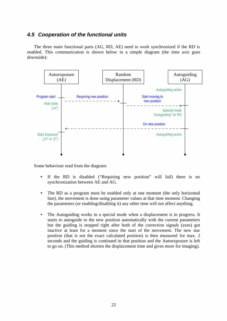
4.5 Cooperation of the functional units
The three main functional parts (AG, RD, AE) need to work synchronized if the RD is enabled. This communication is shown below in a simple diagram (the time axis goes downside):
Some behaviour read from the diagram:
• If the RD is disabled (“Requiring new position” will fail) there is no synchronization between AE and AG.
• The RD as a program must be enabled only at one moment (the only horizontal line), the movement is done using parameter values at that time moment. Changing the parameters (or enabling/disabling it) any other time will not affect anything.
• The Autoguiding works in a special mode when a displacement is in progress. It starts to autoguide to the new position automatically with the current parameters but the guiding is stopped right after both of the correction signals (axes) got inactive at least for a moment since the start of the movement. The new star position (that is not the exact calculated position) is then measured for max. 2 seconds and the guiding is continued in that position and the Autoexposure is left to go on. (This method shorten the displacement time and gives more for imaging).
22
Autoexposure (AE)
Random Displacement (RD)
Autoguiding(AG)
Wait state(„w”)
Program start Requiring new position Start moving to new position
Autoguiding active
Special mode “Autoguiding” for RD
On new position
Autoguiding activeStart Exposure(„m” or „E”)
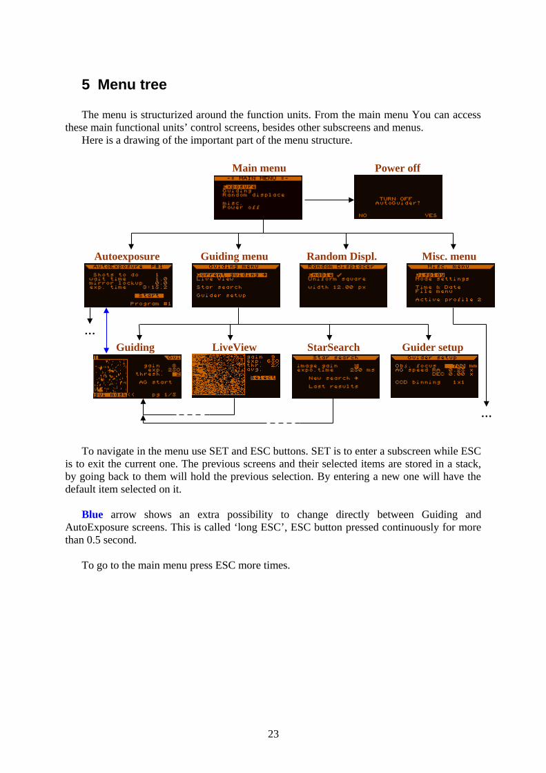
5 Menu tree
The menu is structurized around the function units. From the main menu You can access these main functional units’ control screens, besides other subscreens and menus.
Here is a drawing of the important part of the menu structure.
To navigate in the menu use SET and ESC buttons. SET is to enter a subscreen while ESC is to exit the current one. The previous screens and their selected items are stored in a stack, by going back to them will hold the previous selection. By entering a new one will have the default item selected on it.
Blue arrow shows an extra possibility to change directly between Guiding and AutoExposure screens. This is called ‘long ESC’, ESC button pressed continuously for more than 0.5 second.
To go to the main menu press ESC more times.
23
Main menu
Autoexposure Guiding menu Random Displ. Misc. menu
Guiding LiveView StarSearch Guider setup
…
Power off
…
5.1 Screens and functions detailed
Some explanation for the next (screen-descriptor) sections and its items:
With blue color the item as it apperas on the screen; after it in caret, separated with comma (if it has):
o type of it (see 3.2.2);o limits (minimum and maximum);
after the caret: information about the storage behaviour:o if nothing stays here the item value (if any) is not stored anywhere;o global = the variable item is stored at power-foff but independent of the
profiles;o profile = the variable item is a profile variable, stored at power-off,
changed by profile change.
For each screen description section there is a screenshot from the device (right to the section title) to identify the items more easily.
24
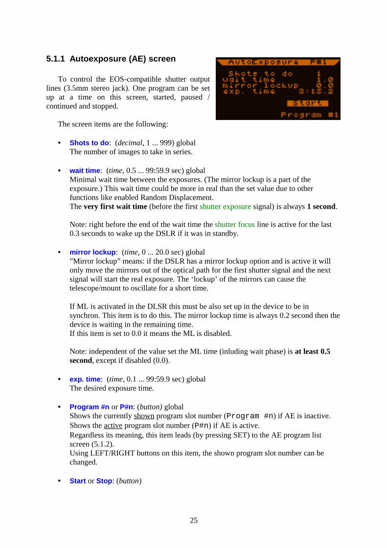
5.1.1 Autoexposure (AE) screen
To control the EOS-compatible shutter output lines (3.5mm stereo jack). One program can be set up at a time on this screen, started, paused / continued and stopped.
The screen items are the following:
• Shots to do: (decimal, 1 ... 999) globalThe number of images to take in series.
• wait time: (time, 0.5 ... 99:59.9 sec) globalMinimal wait time between the exposures. (The mirror lockup is a part of the exposure.) This wait time could be more in real than the set value due to other functions like enabled Random Displacement.The very first wait time (before the first shutter exposure signal) is always 1 second.
Note: right before the end of the wait time the shutter focus line is active for the last 0.3 seconds to wake up the DSLR if it was in standby.
• mirror lockup: (time, 0 ... 20.0 sec) global”Mirror lockup” means: if the DSLR has a mirror lockup option and is active it will only move the mirrors out of the optical path for the first shutter signal and the next signal will start the real exposure. The ‘lockup’ of the mirrors can cause the telescope/mount to oscillate for a short time.
If ML is activated in the DLSR this must be also set up in the device to be in synchron. This item is to do this. The mirror lockup time is always 0.2 second then the device is waiting in the remaining time.If this item is set to 0.0 it means the ML is disabled.
Note: independent of the value set the ML time (inluding wait phase) is at least 0.5 second, except if disabled (0.0).
• exp. time: (time, 0.1 ... 99:59.9 sec) globalThe desired exposure time.
• Program #n or P#n: (button) globalShows the currently shown program slot number (Program #n) if AE is inactive. Shows the active program slot number (P#n) if AE is active.Regardless its meaning, this item leads (by pressing SET) to the AE program list screen (5.1.2).Using LEFT/RIGHT buttons on this item, the shown program slot number can be changed.
• Start or Stop: (button)
25
Used to start or stop the program. At stopping the program is interrupted regardless to its current state and the shutter lines go inactive immediately.It is possible to stop the program while it and the DSLR is in ML state. In this case they will be out of synchron, but the DSLR may timeout from ML state and the synchron is okay from that time.
NOTE: You can start only the currently shown program, regardless to multi-type program mode settings.
• Pause or Continue: (button)The program can be paused in the wait state (between the exposures). This item is only shown when the program is running. If Pause is activated, a “P” character at the left bottom part indicates that the program will be paused after the current exposure ended. The item text will be ‘Continue’. The paused state gets active at the last 0.1 second of the wait state of the program.
At the paused state the program variables can be changed. (Meanwhile a running program it is not allowed.) The ‘remaining time’ will stay at 1 second at paused state.
Activating ‘Continue’ will clear the paused state or the signal to pause before the next exposition. If it was in paused state, the next exposure starts immediately.
Note: if the RD function is enabled the next movement is started before the program reaches paused state.
The currently shown program slot number is displayed at the right top, in the header.
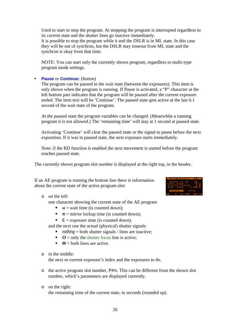
If an AE program is running the bottom line there is information about the current state of the active program slot:
o on the left:one character showing the current state of the AE program
w = wait time (is counted down); m = mirror lockup time (is counted down); E = exposure time (is counted down).
and the next one the actual (physical) shutter signals: nothing = both shutter signals / lines are inactive; Ο = only the shutter focus line is active; Θ = both lines are active.
o in the middle:the next or current exposure’s index and the exposures to do.
o the active program slot number, P#n. This can be different from the shown slot number, which’s parameters are displayed currently.
o on the right:the remaining time of the current state, in seconds (rounded up).
26
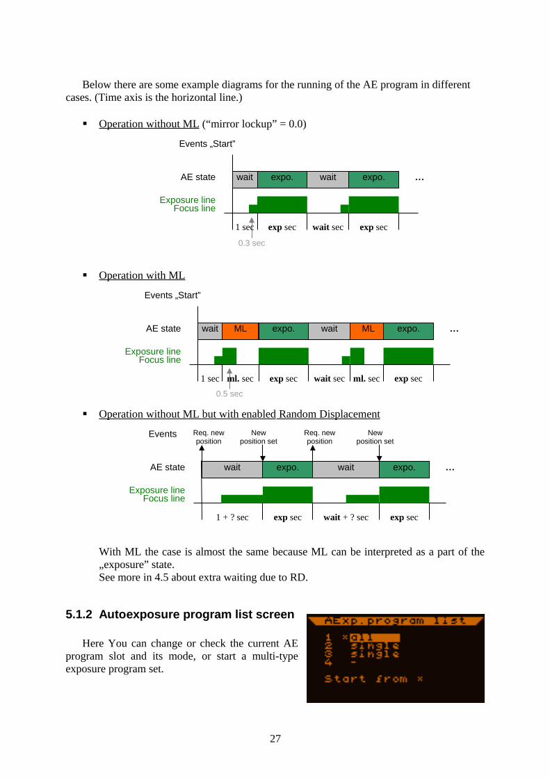
Below there are some example diagrams for the running of the AE program in different cases. (Time axis is the horizontal line.)
Operation without ML (“mirror lockup” = 0.0)
Operation with ML
Operation without ML but with enabled Random Displacement
With ML the case is almost the same because ML can be interpreted as a part of the „exposure” state.See more in 4.5 about extra waiting due to RD.
5.1.2 Autoexposure program list screen
Here You can change or check the current AE program slot and its mode, or start a multi-type exposure program set.
27
AE state
Exposure lineFocus line
„Start”Events
wait expo.
1 sec exp sec
wait expo.
wait sec exp sec
…
0.3 sec
AE state
Exposure lineFocus line
Events
wait expo.
1 sec exp sec
wait
wait sec
…ML ML expo.
exp sec
0.5 sec
ml. sec ml. sec
„Start”
AE state
Exposure lineFocus line
Events
wait expo.
1 + ? sec exp sec
wait expo.
wait + ? sec exp sec
…
Req. new position
New position set
Req. new position
New position set
From fw. 2.03, there are 4 individual AE program slots. (Below 2.03, it’s like there was only the 1st slot.) Each has its own settings, like ‘shots to do’, ‘wait time’ etc. There is a mode for them displayed on this screen, which can be changed by LEFT/RIGHT buttons. Mode defines the behaviour of a program slot when a multi-type program set is started.
On this screen, a star indicates which slot is currently active.
Running ONLY ONE slot’s program:
Select one slot with the cursor and press SET. The slot is the currently active now. Press SET again and the program can be edited at the AE screen, as earlier. After setting the program, use the Start button.
Doing this way, this program slot is started only, regardless to its multi-type program mode settings. All the exposures will be taken and the active program slot will remain the same. After taking all the exposures of this slot, the AE will go idle (stopped).
Running MULTI-type program set :
Set up / edit all the program slots You want to use. Then change their program modes with LEFT/RIGHT, set the active program slot (*) and start it with Start from * item. The previous AE screen is shown, where You can see what the AE is doing.
The following behaviour is used for each program slot mode:
all: take all the exposures in this slot, then go to next slotsingle: take a single exposure by this slot and go to next slot-: do nothing, go to next slot (means: slot not used)
‘Go to next slot’ says, that the active slot number is increased by one. Wrapping is used, 1 comes after 4.
When all the exposures are done in each used slot, AE stops. At starting time, the ‘exposures done’ counters are reset to zero for every slot.
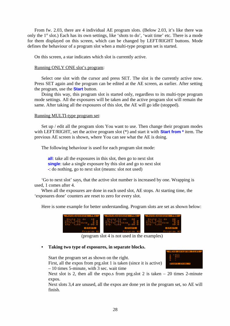
Here is some example for better understanding. Program slots are set as shown below:
(program slot 4 is not used in the examples)
• Taking two type of exposures, in separate blocks.
Start the program set as shown on the right.First, all the expos from prg.slot 1 is taken (since it is active) – 10 times 5-minute, with 3 sec. wait timeNext slot is 2, then all the expo.s from prg.slot 2 is taken – 20 times 2-minute expos.Next slots 3,4 are unused, all the expos are done yet in the program set, so AE will finish.
28
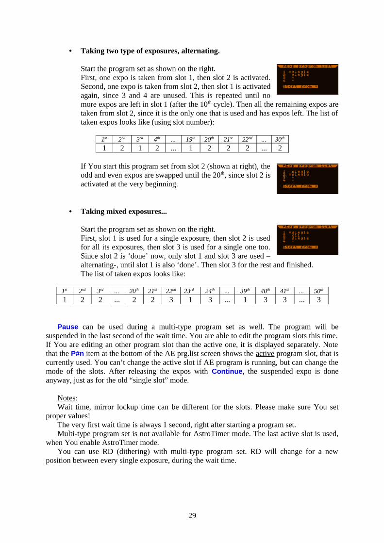
• Taking two type of exposures, alternating.
Start the program set as shown on the right. First, one expo is taken from slot 1, then slot 2 is activated. Second, one expo is taken from slot 2, then slot 1 is activated again, since 3 and 4 are unused. This is repeated until no more expos are left in slot 1 (after the 10th cycle). Then all the remaining expos are taken from slot 2, since it is the only one that is used and has expos left. The list of taken expos looks like (using slot number):
1st 2nd 3rd 4th ... 19th 20th 21st 22nd ... 30th
1 2 1 2 ... 1 2 2 2 ... 2
If You start this program set from slot 2 (shown at right), the odd and even expos are swapped until the 20th, since slot 2 is activated at the very beginning.
• Taking mixed exposures...
Start the program set as shown on the right. First, slot 1 is used for a single exposure, then slot 2 is used for all its exposures, then slot 3 is used for a single one too. Since slot 2 is ‘done’ now, only slot 1 and slot 3 are used –alternating-, until slot 1 is also ‘done’. Then slot 3 for the rest and finished.The list of taken expos looks like:
1st 2nd 3rd ... 20th 21st 22nd 23rd 24th ... 39th 40th 41st ... 50th
1 2 2 ... 2 2 3 1 3 ... 1 3 3 ... 3
Pause can be used during a multi-type program set as well. The program will be suspended in the last second of the wait time. You are able to edit the program slots this time. If You are editing an other program slot than the active one, it is displayed separately. Note that the P#n item at the bottom of the AE prg.list screen shows the active program slot, that is currently used. You can’t change the active slot if AE program is running, but can change the mode of the slots. After releasing the expos with Continue, the suspended expo is done anyway, just as for the old “single slot” mode.
Notes:Wait time, mirror lockup time can be different for the slots. Please make sure You set
proper values!The very first wait time is always 1 second, right after starting a program set.Multi-type program set is not available for AstroTimer mode. The last active slot is used,
when You enable AstroTimer mode.You can use RD (dithering) with multi-type program set. RD will change for a new
position between every single exposure, during the wait time.
29
5.1.3 Random Displacement (RD) screen
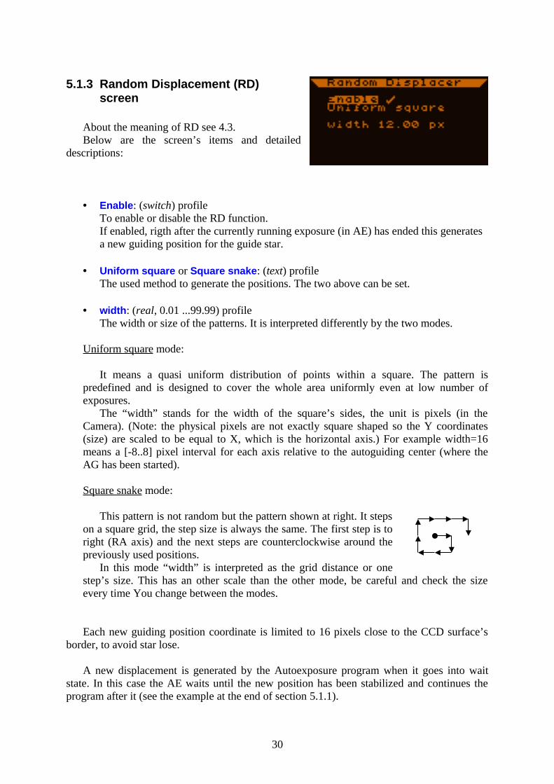
About the meaning of RD see 4.3.Below are the screen’s items and detailed
descriptions:
• Enable: (switch) profileTo enable or disable the RD function.If enabled, rigth after the currently running exposure (in AE) has ended this generates a new guiding position for the guide star.
• Uniform square or Square snake: (text) profileThe used method to generate the positions. The two above can be set.
• width: (real, 0.01 ...99.99) profileThe width or size of the patterns. It is interpreted differently by the two modes.
Uniform sq uare mode:
It means a quasi uniform distribution of points within a square. The pattern is predefined and is designed to cover the whole area uniformly even at low number of exposures.
The “width” stands for the width of the square’s sides, the unit is pixels (in the Camera). (Note: the physical pixels are not exactly square shaped so the Y coordinates (size) are scaled to be equal to X, which is the horizontal axis.) For example width=16 means a [-8..8] pixel interval for each axis relative to the autoguiding center (where the AG has been started).
Square snake mode:
This pattern is not random but the pattern shown at right. It steps on a square grid, the step size is always the same. The first step is to right (RA axis) and the next steps are counterclockwise around the previously used positions.
In this mode “width” is interpreted as the grid distance or one step’s size. This has an other scale than the other mode, be careful and check the size every time You change between the modes.
Each new guiding position coordinate is limited to 16 pixels close to the CCD surface’s border, to avoid star lose.
A new displacement is generated by the Autoexposure program when it goes into wait state. In this case the AE waits until the new position has been stabilized and continues the program after it (see the example at the end of section 5.1.1).
30

The RD positions are fix so reproducable. The positions are indexed in the device that starts from 0 at power-on. This first position (offset) is always (0,0). Later the index grows but can’t be reset to 0 currently. If You stop the autoguiding and restart again, remember that the star may be located somewhere but not where it was at starting the autoguiding. In this case the autoguiding center changes and the new RD movements are done around that point.
The RD movement is not done exactly. The new position may differ from the calculated one a little bit. This behaviour is to save time at RD movement, leaving more time for the exposures.
31
5.1.4 Misc. screen
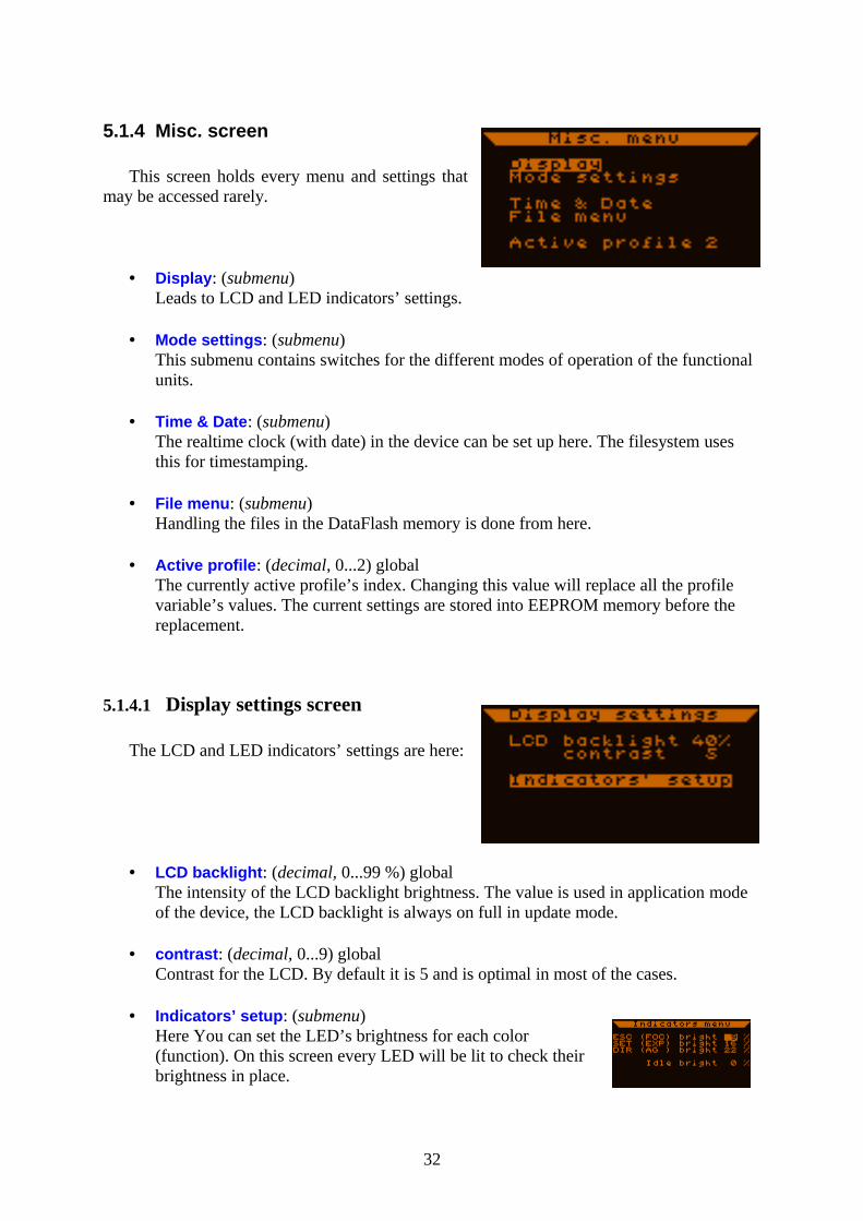
This screen holds every menu and settings that may be accessed rarely.
• Display: (submenu) Leads to LCD and LED indicators’ settings.
• Mode settings: (submenu)This submenu contains switches for the different modes of operation of the functional units.
• Time & Date: (submenu)The realtime clock (with date) in the device can be set up here. The filesystem uses this for timestamping.
• File menu: (submenu)Handling the files in the DataFlash memory is done from here.
• Active profile: (decimal, 0...2) globalThe currently active profile’s index. Changing this value will replace all the profile variable’s values. The current settings are stored into EEPROM memory before the replacement.
5.1.4.1 Display settings screen
The LCD and LED indicators’ settings are here:
• LCD backlight: (decimal, 0...99 %) globalThe intensity of the LCD backlight brightness. The value is used in application mode of the device, the LCD backlight is always on full in update mode.
• contrast: (decimal, 0...9) globalContrast for the LCD. By default it is 5 and is optimal in most of the cases.
• Indicators’ setup: (submenu)Here You can set the LED’s brightness for each color (function). On this screen every LED will be lit to check their brightness in place.
32
Currently the indicated events or states are constant, can’t be changed: ESC (blue): shutter focus line active SET (green): shutter exposure line active directions (red): the RA autoguiding signals horizontaly (left-right), the
DEC signals vertically (up-down).
Each brightness can be next to the bright item in percentage of the full light.
Idle bright mean the value to be used (for all the indicators) when they are not active.
5.1.4.2 Mode settings screen
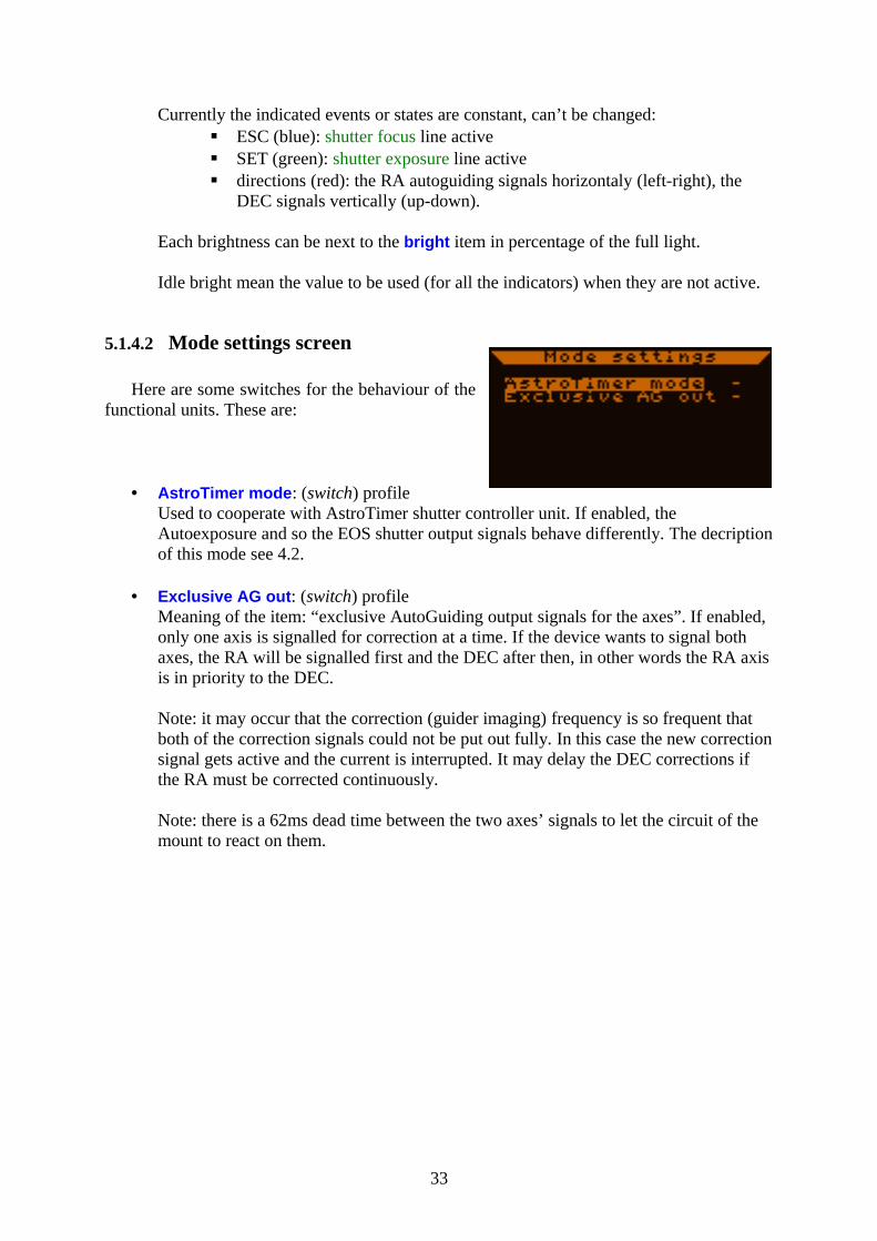
Here are some switches for the behaviour of the functional units. These are:
• AstroTimer mode: (switch) profileUsed to cooperate with AstroTimer shutter controller unit. If enabled, the Autoexposure and so the EOS shutter output signals behave differently. The decription of this mode see 4.2.
• Exclusive AG out: (switch) profileMeaning of the item: “exclusive AutoGuiding output signals for the axes”. If enabled, only one axis is signalled for correction at a time. If the device wants to signal both axes, the RA will be signalled first and the DEC after then, in other words the RA axis is in priority to the DEC.
Note: it may occur that the correction (guider imaging) frequency is so frequent that both of the correction signals could not be put out fully. In this case the new correction signal gets active and the current is interrupted. It may delay the DEC corrections if the RA must be corrected continuously.
Note: there is a 62ms dead time between the two axes’ signals to let the circuit of the mount to react on them.
33
5.1.4.3 Date and time screen
You can set the realtime clock and date here. The format is displayed on the screen: year-month-day and hours:minutes.
The seconds are also displayed but can’t be changed. After setting a new date the device checks it and limits the day value. Always recheck the displayed date after changing it.
This screen apears right after power-on (from Firmware 01.21). If the filesystem is to be used set the date and time properly, timestamps will be instered into the file.
Note: changing the date ant time items takes place immediately. If a file is open and data is being stored into it the timestamps will change suddenly causing the data flow getting a bit confused. Only set a new date or time when no file is open or do it properly only once after power-on.
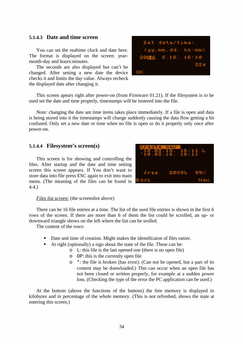
5.1.4.4 Filesystem’s screen(s)
This screen is for showing and controlling the files. After startup and the date and time setting screen this screen appears. If You don’t want to store data into file press ESC again to exit into main menu. (The meaning of the files can be found in 4.4.)
Files list screen: (the screenshot above)
There can be 16 file entries at a time. The list of the used file entries is shown in the first 6 rows of the screen. If there are more than 6 of them the list could be scrolled, an up- or downward triangle shows on the left where the list can be srolled.
The content of the rows:
Date and time of creation. Might makes the identificaton of files easier. At right (optionally) a sign about the state of the file. These can be:
o L: this file is the last opened one (there is no open file)o OP: this is the currently open fileo *: the file is broken (has error). (Can not be opened, but a part of its
content may be donwloaded.) This can occur when an open file has not been closed or written properly, for example at a sudden power loss. (Checking the type of the error the PC application can be used.)
At the bottom (above the functions of the buttons) the free memory is displayed in kilobytes and in percentage of the whole memory. (This is not refreshed, shows the state at entering this screen.)
34
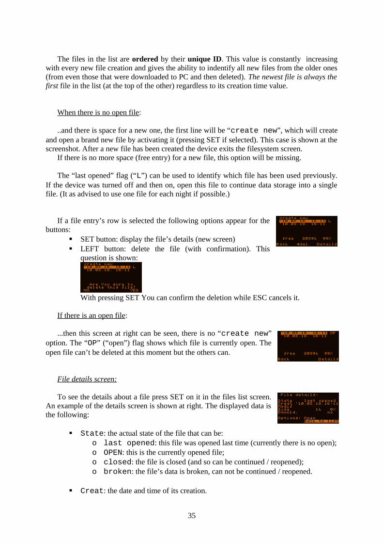
The files in the list are ordered by their unique ID. This value is constantly increasing with every new file creation and gives the ability to indentify all new files from the older ones (from even those that were downloaded to PC and then deleted). The newest file is always the first file in the list (at the top of the other) regardless to its creation time value.
When there is no open file:
..and there is space for a new one, the first line will be “create new”, which will create and open a brand new file by activating it (pressing SET if selected). This case is shown at the screenshot. After a new file has been created the device exits the filesystem screen.
If there is no more space (free entry) for a new file, this option will be missing.
The “last opened” flag (“L”) can be used to identify which file has been used previously. If the device was turned off and then on, open this file to continue data storage into a single file. (It as advised to use one file for each night if possible.)
If a file entry’s row is selected the following options appear for the buttons:
SET button: display the file’s details (new screen) LEFT button: delete the file (with confirmation). This
question is shown:
With pressing SET You can confirm the deletion while ESC cancels it.
If there is an open file:
...then this screen at right can be seen, there is no “create new” option. The “OP” (“open”) flag shows which file is currently open. The open file can’t be deleted at this moment but the others can.
F ile details screen:
To see the details about a file press SET on it in the files list screen. An example of the details screen is shown at right. The displayed data is the following:
State: the actual state of the file that can be:o last opened: this file was opened last time (currently there is no open);o OPEN: this is the currently opened file;o closed: the file is closed (and so can be continued / reopened);o broken: the file’s data is broken, can not be continued / reopened.
Creat: the date and time of its creation.
35
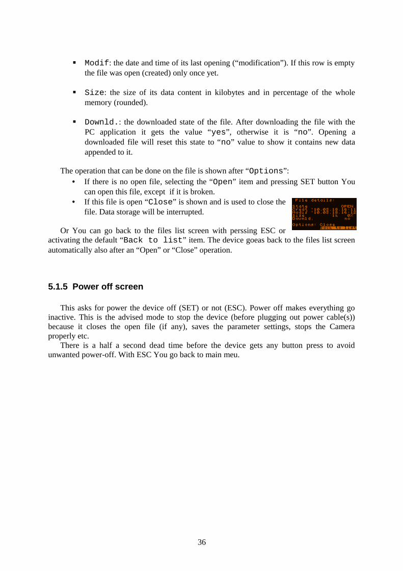
Modif: the date and time of its last opening (“modification”). If this row is empty the file was open (created) only once yet.
Size: the size of its data content in kilobytes and in percentage of the whole memory (rounded).
Downld.: the downloaded state of the file. After downloading the file with the PC application it gets the value “yes”, otherwise it is “no”. Opening a downloaded file will reset this state to “no” value to show it contains new data appended to it.
The operation that can be done on the file is shown after “Options”: • If there is no open file, selecting the “Open” item and pressing SET button You
can open this file, except if it is broken.• If this file is open “Close” is shown and is used to close the
file. Data storage will be interrupted.
Or You can go back to the files list screen with perssing ESC or activating the default “Back to list” item. The device goeas back to the files list screen automatically also after an “Open” or “Close” operation.
5.1.5 Power off screen
This asks for power the device off (SET) or not (ESC). Power off makes everything go inactive. This is the advised mode to stop the device (before plugging out power cable(s)) because it closes the open file (if any), saves the parameter settings, stops the Camera properly etc.
There is a half a second dead time before the device gets any button press to avoid unwanted power-off. With ESC You go back to main meu.
36
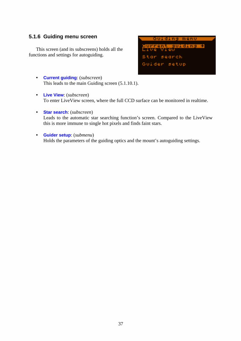
5.1.6 Guiding menu screen
This screen (and its subscreens) holds all the functions and settings for autoguiding.
• Current guiding: (subscreen)This leads to the main Guiding screen (5.1.10.1).
• Live View: (subscreen)To enter LiveView screen, where the full CCD surface can be monitored in realtime.
• Star search: (subscreen)Leads to the automatic star searching function’s screen. Compared to the LiveView this is more immune to single hot pixels and finds faint stars.
• Guider setup: (submenu)Holds the parameters of the guiding optics and the mount’s autoguiding settings.
37
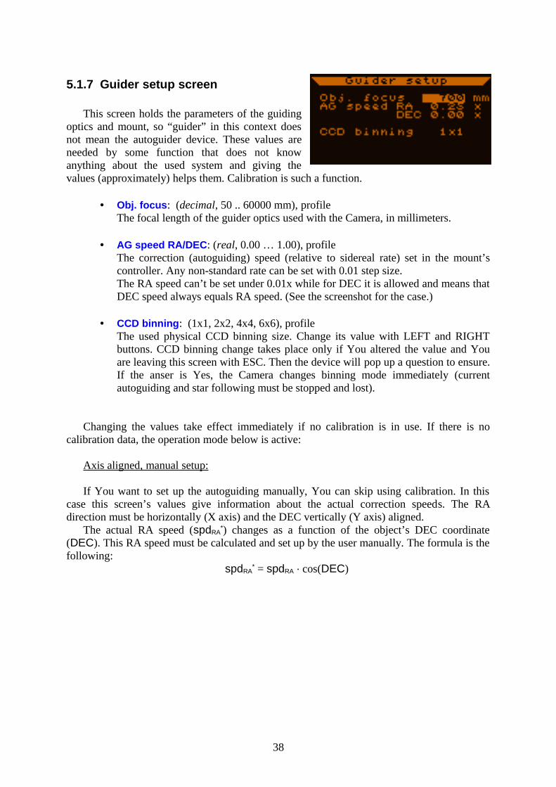
5.1.7 Guider setup screen
This screen holds the parameters of the guiding optics and mount, so “guider” in this context does not mean the autoguider device. These values are needed by some function that does not know anything about the used system and giving the values (approximately) helps them. Calibration is such a function.
• Obj. focus: (decimal, 50 .. 60000 mm), profileThe focal length of the guider optics used with the Camera, in millimeters.
• AG speed RA/DEC: (real, 0.00 … 1.00), profileThe correction (autoguiding) speed (relative to sidereal rate) set in the mount’s controller. Any non-standard rate can be set with 0.01 step size.The RA speed can’t be set under 0.01x while for DEC it is allowed and means that DEC speed always equals RA speed. (See the screenshot for the case.)
• CCD binning: (1x1, 2x2, 4x4, 6x6), profileThe used physical CCD binning size. Change its value with LEFT and RIGHT buttons. CCD binning change takes place only if You altered the value and You are leaving this screen with ESC. Then the device will pop up a question to ensure. If the anser is Yes, the Camera changes binning mode immediately (current autoguiding and star following must be stopped and lost).
Changing the values take effect immediately if no calibration is in use. If there is no calibration data, the operation mode below is active:
Axis aligned, manual setup:
If You want to set up the autoguiding manually, You can skip using calibration. In this case this screen’s values give information about the actual correction speeds. The RA direction must be horizontally (X axis) and the DEC vertically (Y axis) aligned.
The actual RA speed (spdRA*) changes as a function of the object’s DEC coordinate
(DEC). This RA speed must be calculated and set up by the user manually. The formula is the following:
spdRA* = spdRA · cos(DEC)
38
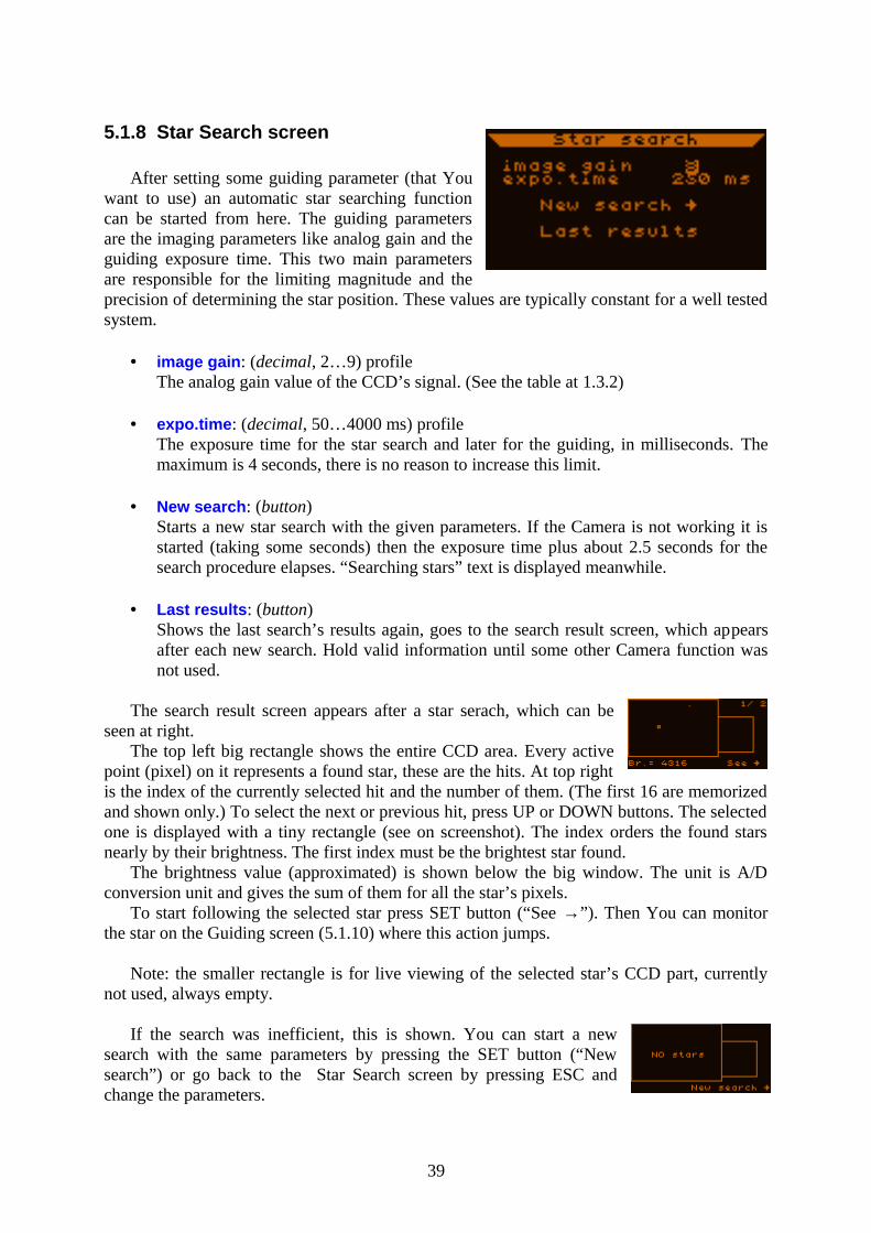
5.1.8 Star Search screen
After setting some guiding parameter (that You want to use) an automatic star searching function can be started from here. The guiding parameters are the imaging parameters like analog gain and the guiding exposure time. This two main parameters are responsible for the limiting magnitude and the precision of determining the star position. These values are typically constant for a well tested system.
• image gain: (decimal, 2…9) profileThe analog gain value of the CCD’s signal. (See the table at 1.3.2)
• expo.time: (decimal, 50…4000 ms) profileThe exposure time for the star search and later for the guiding, in milliseconds. The maximum is 4 seconds, there is no reason to increase this limit.
• New search: (button)Starts a new star search with the given parameters. If the Camera is not working it is started (taking some seconds) then the exposure time plus about 2.5 seconds for the search procedure elapses. “Searching stars” text is displayed meanwhile.
• Last results: (button)Shows the last search’s results again, goes to the search result screen, which appears after each new search. Hold valid information until some other Camera function was not used.
The search result screen appears after a star serach, which can be seen at right.
The top left big rectangle shows the entire CCD area. Every active point (pixel) on it represents a found star, these are the hits. At top right is the index of the currently selected hit and the number of them. (The first 16 are memorized and shown only.) To select the next or previous hit, press UP or DOWN buttons. The selected one is displayed with a tiny rectangle (see on screenshot). The index orders the found stars nearly by their brightness. The first index must be the brightest star found.
The brightness value (approximated) is shown below the big window. The unit is A/D conversion unit and gives the sum of them for all the star’s pixels.
To start following the selected star press SET button (“See →”). Then You can monitor the star on the Guiding screen (5.1.10) where this action jumps.
Note: the smaller rectangle is for live viewing of the selected star’s CCD part, currently not used, always empty.
If the search was inefficient, this is shown. You can start a new search with the same parameters by pressing the SET button (“New search”) or go back to the Star Search screen by pressing ESC and change the parameters.
39

Other notes:The automatic star search method uses a 32 pixel width window. Stars having this huge
image or defocused spots may not result in a hit point or more points close to eachother. Double stars within this size are also identified as single stars.
40
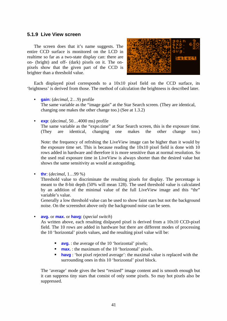
5.1.9 Live View screen
The screen does that it’s name suggests. The entire CCD surface is monitored on the LCD in realtime so far as a two-state display can: there are on- (bright) and off- (dark) pixels on it. The on-pixels show that the given part of the CCD is brighter than a threshold value.
Each displayed pixel corresponds to a 10x10 pixel field on the CCD surface, its ‘brightness’ is derived from those. The method of calculation the brightness is described later.
• gain: (decimal, 2…9) profileThe same variable as the “image gain” at the Star Search screen. (They are identical, changing one makes the other change too.) (See at 1.3.2)
• exp: (decimal, 50…4000 ms) profileThe same variable as the “expo.time” at Star Search screen, this is the exposure time. (They are identical, changing one makes the other change too.)
Note: the frequency of refrshing the LiveView image can be higher than it would by the exposure time set. This is because reading the 10x10 pixel field is done with 10 rows added in hardware and therefore it is more sensitive than at normal resolution. So the used real exposure time in LiveView is always shorter than the desired value but shows the same sensitivity as would at autoguiding.
• thr: (decimal, 1…99 %)Threshold value to discriminate the resulting pixels for display. The percentage is meant to the 8-bit depth (50% will mean 128). The used threshold value is calculated by an addition of the minimal value of the full LiveView image and this “thr” variable’s value.Generally a low threshold value can be used to show faint stars but not the background noise. On the screenshot above only the background noise can be seen.
• avg. or max. or havg: (special switch)As written above, each resulting dislpayed pixel is derived from a 10x10 CCD-pixel field. The 10 rows are added in hardware but there are different modes of processing the 10 ‘horizontal’ pixels values, and the resulting pixel value will be:
avg. : the average of the 10 ‘horizontal’ pixels; max. : the maximum of the 10 ‘horizontal’ pixels. havg : ‘hot pixel rejected average’: the maximal value is replaced with the
surrounding ones in this 10 ‘horizontal’ pixel block.
The ‘average’ mode gives the best “resized” image content and is smooth enough but it can suppress tiny stars that consist of only some pixels. So may hot pixels also be suppressed.
41
The ‘maximum’ mode is for displaying every tiny or single pixels, which can be a faint star so as a hot pixel, use this mode carefully. Moving slightly the telescope will show which pixel is due to a star (it moves with the scope) and which is a hot pixel (stays in place).
The new ‘havg’ mode can be used if single hot pixels are disturbing but don’t forget it suppresses very faint star’s highest pixel value as well and they may become almost invisible.
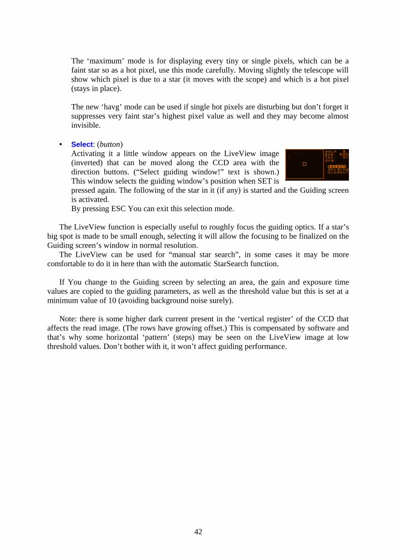
• Select: (button)Activating it a little window appears on the LiveView image (inverted) that can be moved along the CCD area with the direction buttons. (“Select guiding window!” text is shown.) This window selects the guiding window’s position when SET is pressed again. The following of the star in it (if any) is started and the Guiding screen is activated.By pressing ESC You can exit this selection mode.
The LiveView function is especially useful to roughly focus the guiding optics. If a star’s big spot is made to be small enough, selecting it will allow the focusing to be finalized on the Guiding screen’s window in normal resolution.
The LiveView can be used for “manual star search”, in some cases it may be more comfortable to do it in here than with the automatic StarSearch function.
If You change to the Guiding screen by selecting an area, the gain and exposure time values are copied to the guiding parameters, as well as the threshold value but this is set at a minimum value of 10 (avoiding background noise surely).
Note: there is some higher dark current present in the ‘vertical register’ of the CCD that affects the read image. (The rows have growing offset.) This is compensated by software and that’s why some horizontal ‘pattern’ (steps) may be seen on the LiveView image at low threshold values. Don’t bother with it, it won’t affect guiding performance.
42
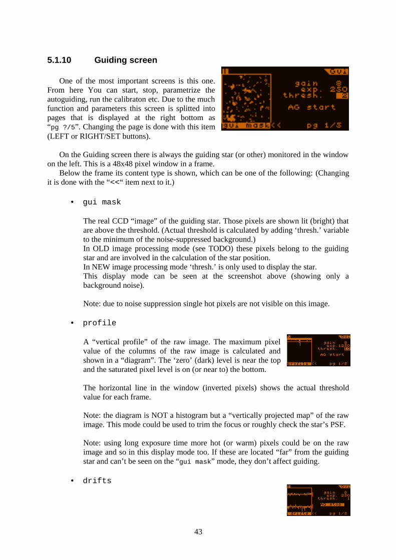
5.1.10 Guiding screen
One of the most important screens is this one. From here You can start, stop, parametrize the autoguiding, run the calibraton etc. Due to the much function and parameters this screen is splitted into pages that is displayed at the right bottom as “pg ?/5”. Changing the page is done with this item (LEFT or RIGHT/SET buttons).
On the Guiding screen there is always the guiding star (or other) monitored in the window on the left. This is a 48x48 pixel window in a frame.
Below the frame its content type is shown, which can be one of the following: (Changing it is done with the “<<“ item next to it.)
• gui mask
The real CCD “image” of the guiding star. Those pixels are shown lit (bright) that are above the threshold. (Actual threshold is calculated by adding ‘thresh.’ variable to the minimum of the noise-suppressed background.)In OLD image processing mode (see TODO) these pixels belong to the guiding star and are involved in the calculation of the star position. In NEW image processing mode ‘thresh.’ is only used to display the star.This display mode can be seen at the screenshot above (showing only a background noise).
Note: due to noise suppression single hot pixels are not visible on this image.
• profile
A “vertical profile” of the raw image. The maximum pixel value of the columns of the raw image is calculated and shown in a “diagram”. The ‘zero’ (dark) level is near the top and the saturated pixel level is on (or near to) the bottom.
The horizontal line in the window (inverted pixels) shows the actual threshold value for each frame.
Note: the diagram is NOT a histogram but a “vertically projected map” of the raw image. This mode could be used to trim the focus or roughly check the star’s PSF.
Note: using long exposure time more hot (or warm) pixels could be on the raw image and so in this display mode too. If these are located “far” from the guiding star and can’t be seen on the “gui mask” mode, they don’t affect guiding.
• drifts
43
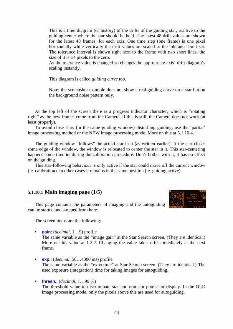
This is a time diagram (or history) of the drifts of the guiding star, realtive to the guiding center where the star should be held. The latest 48 drift values are shown for the latest 48 frames, for each axis. One time step (one frame) is one pixel horizontally while vertically the drift values are scaled to the tolerance limit set. The tolerance interval is shown right next to the frame with two short lines, the size of it is ±4 pixels to the zero.As the tolerance value is changed so changes the appropriate axis’ drift diagram’s scaling instantly.
This diagram is called guiding curve too.
Note: the screenshot example does not show a real guiding curve on a star but on the background noise pattern only.
At the top left of the screen there is a progress indicator character, which is “rotating right” as the new frames come from the Camera. If this is still, the Camera does not work (at least properly).
To avoid close stars (in the same guiding window) disturbing guiding, use the ‘partial’ image processing method or the NEW image processing mode. More on this at 5.1.10.4.
The guiding window “follows” the actual star in it (as written earlier). If the star closes some edge of the window, the window is relocated to center the star in it. This star-centering happens some time ie. during the calibration procedure. Don’t bother with it, it has no effect on the guiding.
This star-following behaviour is only active if the star could move off the current window (ie. calibration). In other cases it remains in the same position (ie. guiding active).
5.1.10.1 Main imaging page (1/5)
This page contains the parameters of imaging and the autoguiding can be started and stopped from here.
The screen items are the following:
• gain: (decimal, 1…9) profileThe same variable as the “image gain” at the Star Search screen. (They are identical.) More on this value at 1.3.2. Changing the value takes effect imediately at the next frame.
• exp.: (decimal, 50…4000 ms) profileThe same variable as the “expo.time” at Star Search screen. (They are identical.) The used exposure (integration) time for taking images for autoguiding.
• thresh.: (decimal, 1…99 %)The threshold value to discriminate star and non-star pixels for display. In the OLD image processing mode, only the pixels above this are used for autoguiding.
44
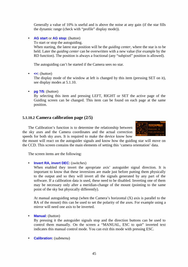
Generally a value of 10% is useful and is above the noise at any gain (if the star fills the dynamic range (check with “profile” display mode)).
• AG start or AG stop: (button)To start or stop the autoguiding.When starting, the latest star position will be the guiding center, where the star is to be held. Later the guiding center can be overwritten with a new value (for example by the RD function). The position is always a fractional (any “subpixel” position is allowed).
The autoguiding can’t be started if the Camera sees no star.
• <<: (button)The display mode of the window at left is changed by this item (pressing SET on it), see display modes at 5.1.10.
• pg ?/5: (button)By selecting this item and pressing LEFT, RIGHT or SET the active page of the Guiding screen can be changed. This item can be found on each page at the same position.
5.1.10.2 Camera calibration page (2/5)
The Calibration’s function is to determine the relationship between the sky axes and the Camera coordinates and the actual correction speeds for both sky axes. It is required to make the device know how the mount will react on the autoguider signals and know how the guiding star will move on the CCD. This screen contains the main elements of setting this ‘camera orientation’ data.
The screen items are the following:
• Invert RA, invert DEC: (switches)When enabled they invert the apropriate axis’ autoguider signal direction. It is important to know that these inversions are made just before putting them physically to the output and so they will invert all the signals generated by any part of the software. If a calibration data is used, these need to be disabled. Inverting one of them may be necessary only after a meridian-change of the mount (pointing to the same point of the sky but physically differently).
At manual autoguiding setup (when the Camera’s horizontal (X) axis is parallel to the RA of the mount) this can be used to set the polarity of the axes. For example using a mirror will need one axis to be inverted.
• Manual: (button)By pressing it the autoguider signals stop and the direction buttons can be used to control them manually. On the screen a “MANUAL, ESC to quit” inverted text indicates this manual control mode. You can exit this mode with pressing ESC.
• Calibration: (submenu)
45
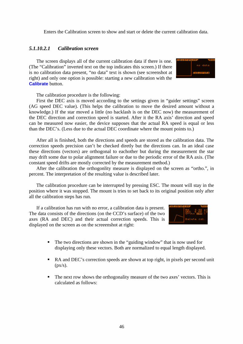
Enters the Calibration screen to show and start or delete the current calibration data.
5.1.10.2.1 Calibration screen
The screen displays all of the current calibration data if there is one. (The “Calibration” inverted text on the top indicates this screen.) If there is no calibration data present, “no data” text is shown (see screenshot at right) and only one option is possible: starting a new calibration with the Calibrate button.
The calibration procedure is the following:First the DEC axis is moved according to the settings given in “guider settings” screen
(AG speed DEC value). (This helps the calibration to move the desired amount without a knowledge.) If the star moved a little (no backlash is on the DEC now) the measurement of the DEC direction and correction speed is started. After it the RA axis’ direction and speed can be measured now easier, the device supposes that the actual RA speed is equal or less than the DEC’s. (Less due to the actual DEC coordinate where the mount points to.)
After all is finished, both the directions and speeds are stored as the calibration data. The correction speeds precision can’t be checked diretly but the directions can. In an ideal case these directions (vectors) are orthogonal to eachother but during the measurement the star may drift some due to polar alignment failure or due to the periodic error of the RA axis. (The constant speed drifts are mostly corrected by the measurement method.)
After the calibration the orthogonlity measure is displayed on the screen as “ortho.”, in percent. The interpretation of the resulting value is described later.
The calibration procedure can be interrupted by pressing ESC. The mount will stay in the position where it was stopped. The mount is tries to set back to its original position only after all the calibration steps has run.
If a calibration has run with no error, a calibration data is present. The data consists of the directions (on the CCD’s surface) of the two axes (RA and DEC) and their actual correction speeds. This is displayed on the screen as on the screeenshot at right:
The two directions are shown in the “guiding window” that is now used for displaying only these vectors. Both are normalized to equal length displayed.
RA and DEC’s correction speeds are shown at top right, in pixels per second unit (px/s).
The next row shows the orthogonality measure of the two axes’ vectors. This is calculated as follows:
46
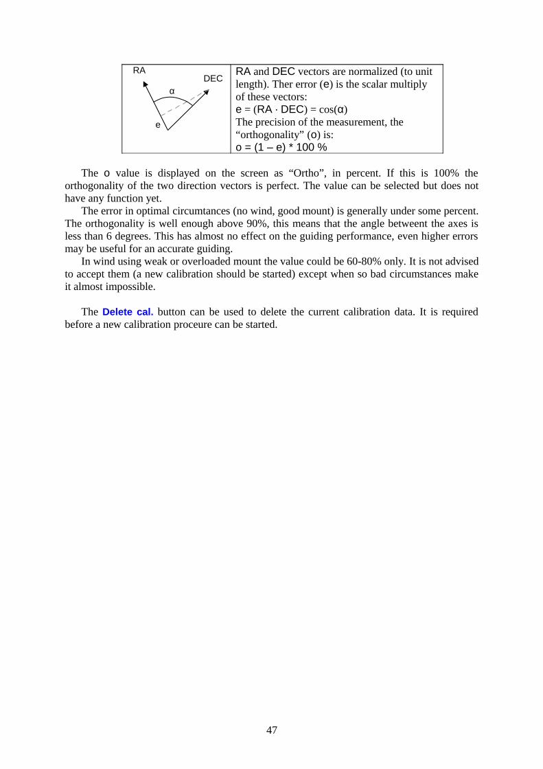
RA and DEC vectors are normalized (to unit length). Ther error (e) is the scalar multiply of these vectors:e = (RA · DEC) = cos(α)The precision of the measurement, the “orthogonality” (o) is:o = (1 – e) * 100 %
The o value is displayed on the screen as “Ortho”, in percent. If this is 100% the orthogonality of the two direction vectors is perfect. The value can be selected but does not have any function yet.
The error in optimal circumtances (no wind, good mount) is generally under some percent. The orthogonality is well enough above 90%, this means that the angle betweent the axes is less than 6 degrees. This has almost no effect on the guiding performance, even higher errors may be useful for an accurate guiding.
In wind using weak or overloaded mount the value could be 60-80% only. It is not advised to accept them (a new calibration should be started) except when so bad circumstances make it almost impossible.
The Delete cal. button can be used to delete the current calibration data. It is required before a new calibration proceure can be started.
47
RADEC
e
α
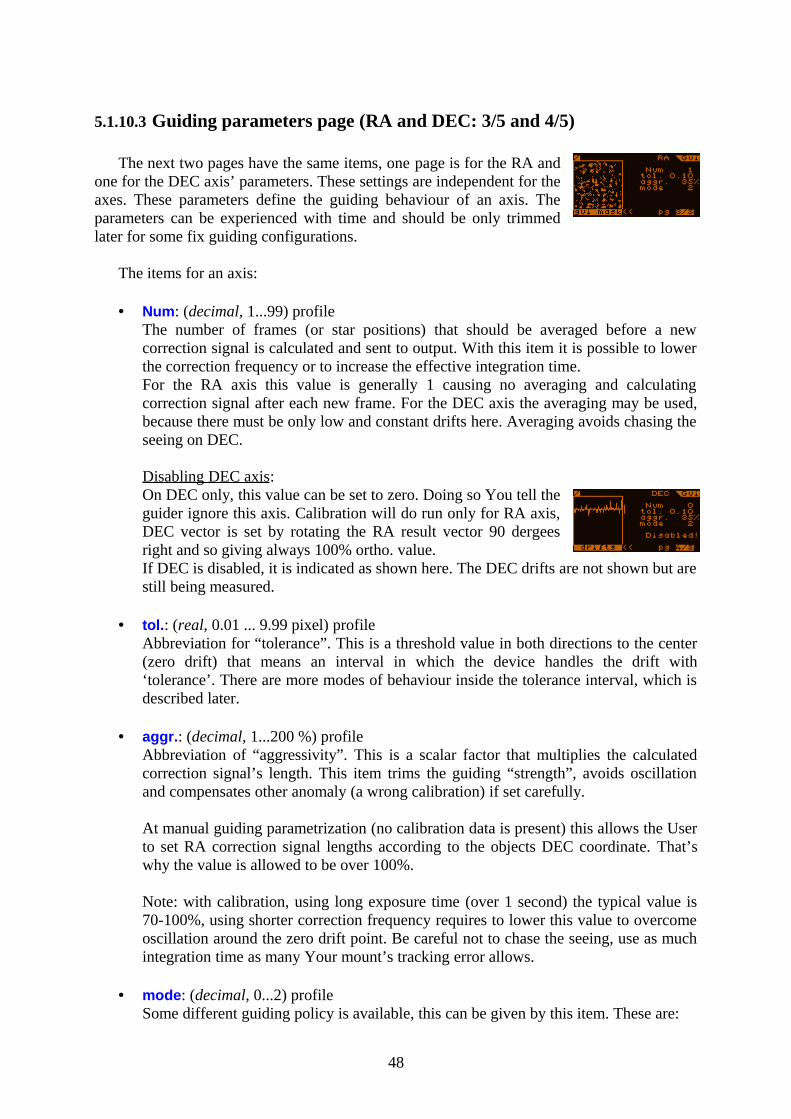
5.1.10.3 Guiding parameters page (RA and DEC: 3/5 and 4/5)
The next two pages have the same items, one page is for the RA and one for the DEC axis’ parameters. These settings are independent for the axes. These parameters define the guiding behaviour of an axis. The parameters can be experienced with time and should be only trimmed later for some fix guiding configurations.
The items for an axis:
• Num: (decimal, 1...99) profileThe number of frames (or star positions) that should be averaged before a new correction signal is calculated and sent to output. With this item it is possible to lower the correction frequency or to increase the effective integration time.For the RA axis this value is generally 1 causing no averaging and calculating correction signal after each new frame. For the DEC axis the averaging may be used, because there must be only low and constant drifts here. Averaging avoids chasing the seeing on DEC.
Disabling DEC axis: On DEC only, this value can be set to zero. Doing so You tell the guider ignore this axis. Calibration will do run only for RA axis, DEC vector is set by rotating the RA result vector 90 dergees right and so giving always 100% ortho. value.If DEC is disabled, it is indicated as shown here. The DEC drifts are not shown but are still being measured.
• tol.: (real, 0.01 ... 9.99 pixel) profileAbbreviation for “tolerance”. This is a threshold value in both directions to the center (zero drift) that means an interval in which the device handles the drift with ‘tolerance’. There are more modes of behaviour inside the tolerance interval, which is described later.
• aggr.: (decimal, 1...200 %) profileAbbreviation of “aggressivity”. This is a scalar factor that multiplies the calculated correction signal’s length. This item trims the guiding “strength”, avoids oscillation and compensates other anomaly (a wrong calibration) if set carefully.
At manual guiding parametrization (no calibration data is present) this allows the User to set RA correction signal lengths according to the objects DEC coordinate. That’s why the value is allowed to be over 100%.
Note: with calibration, using long exposure time (over 1 second) the typical value is 70-100%, using shorter correction frequency requires to lower this value to overcome oscillation around the zero drift point. Be careful not to chase the seeing, use as much integration time as many Your mount’s tracking error allows.
• mode: (decimal, 0...2) profileSome different guiding policy is available, this can be given by this item. These are:
48
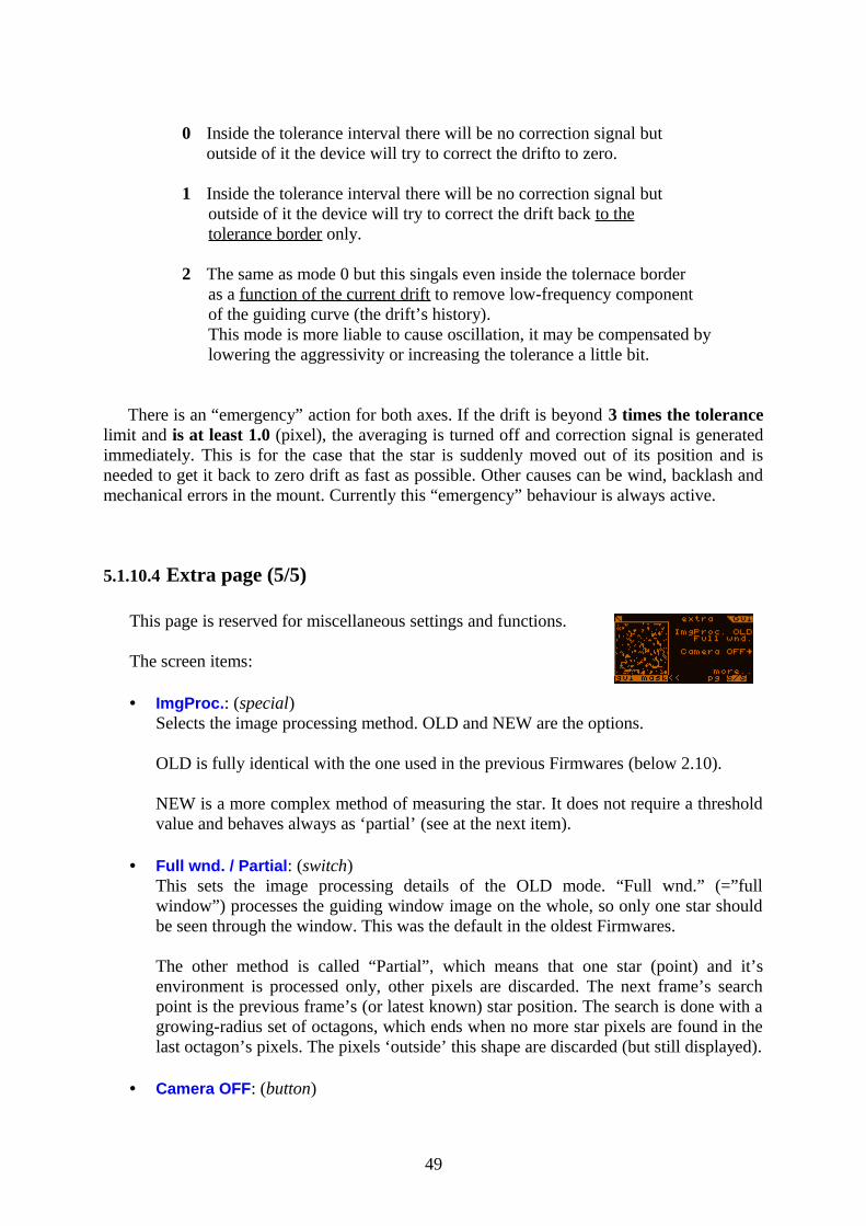
0 Inside the tolerance interval there will be no correction signal butoutside of it the device will try to correct the drifto to zero.
1 Inside the tolerance interval there will be no correction signal butoutside of it the device will try to correct the drift back to thetolerance border only.
2 The same as mode 0 but this singals even inside the tolernace borderas a function of the current drift to remove low-frequency componentof the guiding curve (the drift’s history).This mode is more liable to cause oscillation, it may be compensated by lowering the aggressivity or increasing the tolerance a little bit.
There is an “emergency” action for both axes. If the drift is beyond 3 times the tolerance limit and is at least 1.0 (pixel), the averaging is turned off and correction signal is generated immediately. This is for the case that the star is suddenly moved out of its position and is needed to get it back to zero drift as fast as possible. Other causes can be wind, backlash and mechanical errors in the mount. Currently this “emergency” behaviour is always active.
5.1.10.4 Extra page (5/5)
This page is reserved for miscellaneous settings and functions.
The screen items:
• ImgProc.: (special)Selects the image processing method. OLD and NEW are the options.
OLD is fully identical with the one used in the previous Firmwares (below 2.10).
NEW is a more complex method of measuring the star. It does not require a threshold value and behaves always as ‘partial’ (see at the next item).
• Full wnd. / Partial: (switch)This sets the image processing details of the OLD mode. “Full wnd.” (=”full window”) processes the guiding window image on the whole, so only one star should be seen through the window. This was the default in the oldest Firmwares.
The other method is called “Partial”, which means that one star (point) and it’s environment is processed only, other pixels are discarded. The next frame’s search point is the previous frame’s (or latest known) star position. The search is done with a growing-radius set of octagons, which ends when no more star pixels are found in the last octagon’s pixels. The pixels ‘outside’ this shape are discarded (but still displayed).
• Camera OFF: (button)
49
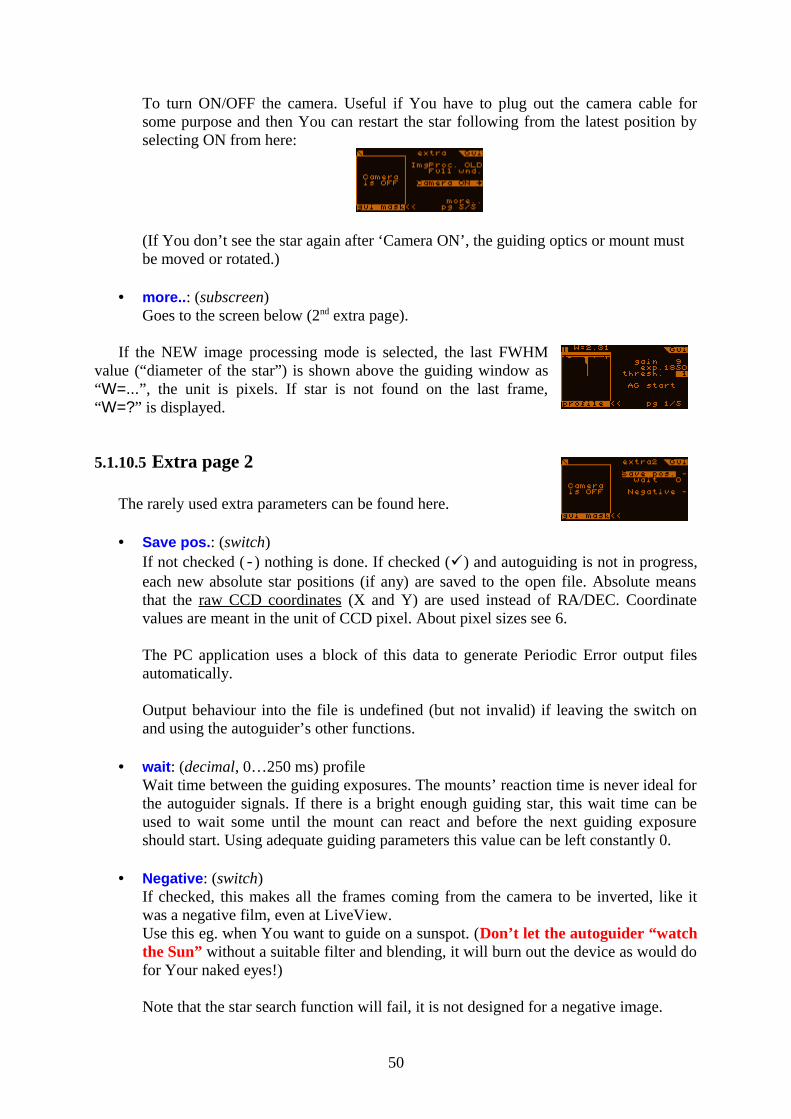
To turn ON/OFF the camera. Useful if You have to plug out the camera cable for some purpose and then You can restart the star following from the latest position by selecting ON from here:
(If You don’t see the star again after ‘Camera ON’, the guiding optics or mount must be moved or rotated.)
• more..: (subscreen)Goes to the screen below (2nd extra page).
If the NEW image processing mode is selected, the last FWHM value (“diameter of the star”) is shown above the guiding window as “W=...”, the unit is pixels. If star is not found on the last frame, “W=?” is displayed.
5.1.10.5 Extra page 2
The rarely used extra parameters can be found here.
• Save pos.: (switch)If not checked (-) nothing is done. If checked () and autoguiding is not in progress, each new absolute star positions (if any) are saved to the open file. Absolute means that the raw CCD coordinates (X and Y) are used instead of RA/DEC. Coordinate values are meant in the unit of CCD pixel. About pixel sizes see 6.
The PC application uses a block of this data to generate Periodic Error output files automatically.
Output behaviour into the file is undefined (but not invalid) if leaving the switch on and using the autoguider’s other functions.
• wait: (decimal, 0…250 ms) profileWait time between the guiding exposures. The mounts’ reaction time is never ideal for the autoguider signals. If there is a bright enough guiding star, this wait time can be used to wait some until the mount can react and before the next guiding exposure should start. Using adequate guiding parameters this value can be left constantly 0.
• Negative: (switch)If checked, this makes all the frames coming from the camera to be inverted, like it was a negative film, even at LiveView.Use this eg. when You want to guide on a sunspot. (Don’t let the autoguider “watch the Sun” without a suitable filter and blending, it will burn out the device as would do for Your naked eyes!)
Note that the star search function will fail, it is not designed for a negative image.
50
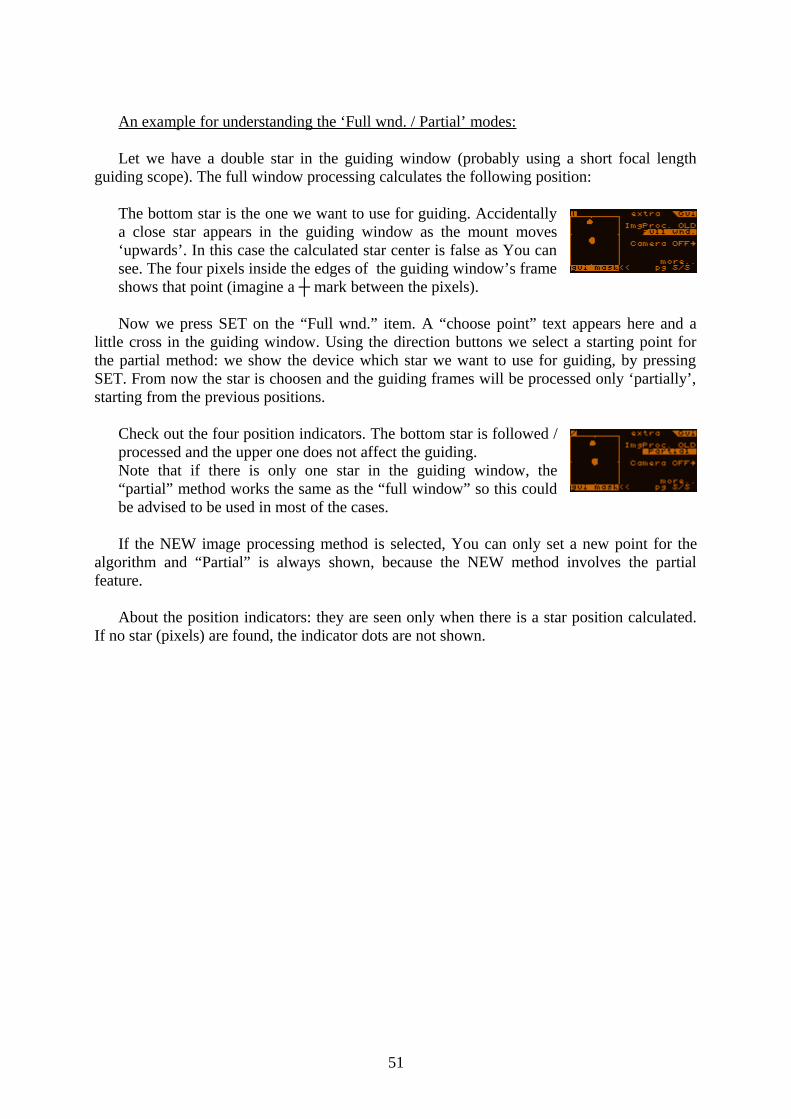
An example for understanding the ‘Full wnd. / Partial’ modes:
Let we have a double star in the guiding window (probably using a short focal length guiding scope). The full window processing calculates the following position:
The bottom star is the one we want to use for guiding. Accidentally a close star appears in the guiding window as the mount moves ‘upwards’. In this case the calculated star center is false as You can see. The four pixels inside the edges of the guiding window’s frame shows that point (imagine a ┼ mark between the pixels).
Now we press SET on the “Full wnd.” item. A “choose point” text appears here and a little cross in the guiding window. Using the direction buttons we select a starting point for the partial method: we show the device which star we want to use for guiding, by pressing SET. From now the star is choosen and the guiding frames will be processed only ‘partially’, starting from the previous positions.
Check out the four position indicators. The bottom star is followed / processed and the upper one does not affect the guiding.Note that if there is only one star in the guiding window, the “partial” method works the same as the “full window” so this could be advised to be used in most of the cases.
If the NEW image processing method is selected, You can only set a new point for the algorithm and “Partial” is always shown, because the NEW method involves the partial feature.
About the position indicators: they are seen only when there is a star position calculated. If no star (pixels) are found, the indicator dots are not shown.
51

6 More detailed about...
6.1 ... CCD binning
Hereby I try to describe the hardware binning operation modes of the Camera. The following four modes can be selected:
Binning mode
CCD area(pixels)
Binned pixel size (μm)
1 × 1 752 × 582 4.85 × 4.65
2 × 2 376 × 291 9.7 × 9.3
4 × 4 188 × 145 19.4 × 18.6
6 × 6 125 × 97 29.1 × 27.9
The default is 1×1, used in the Firmwares below 1.99.
Note that the guiding window is constant 48×48 pixels, for example at 6×6 binning mode the guiding window covers half of the available vertical area (48 out of 97 pixels). You can see the guiding window sizes on the LiveView screen when selecting the guiding window.
As the pixel size ‘grows’ (one binned pixel) so do the other parameters. The thermal dark current is multiplied with the binning block size (N×N) but the total sensitivity of the binned pixel changes the same way. There is some ‘amp glow’ (at left top) due to the CCD construction, You could see this in LiveView with long exposure time. This also increases with the binning as a part of the increased sensitivity. The left top area of the CCD may be not used if the glow seems to be too hard.
Due to the increased horizontal transfer time (binned pixel), the readout noise grows some with the binning size. My measures showed less than +40% for the 6×6 mode so the read noise is still below 10 electrons for most of the Camera instances in any modes.
Using binning modes is advised only for long (above ~1.5m) focal length guiding scopes or optics. Use binning only if Your guiding star is way too fast moving and has a ‘large spot’. Don’t use it for short focal length guide scopes because it could only make the guiding accuracy lower!
52
6.2 ... the NEW image processing method
From Firmware 2.10 this option is available on the extra (5/5) page of the guiding screen.This method is much more complex than the default (OLD) one. I list the advantages and
drawbacks of this mode.
Advantages:• No need of a threshold value. (Only for display.)
By construction, the method automatically models the background and weights star pixels.
• Designed to tolerate unconventional star shapes, mainly for the forthcoming multi-star guiding mode. This gives less star position noise and this does not depend on a “bad threshold setting”.Practical for very hard separable doublets too.
• Involved ‘partial’ mode.Practical for processing one of a well separated doublet.
• FWHM value approximation is available from the processing.Simplified, “Full Width at Half Maximum” is a value giving the “diameter” of a star image.Practical to set an optimal focus.
Drawbacks:• Slower computation time. For a normal, small star, it takes only some hundredths
of a second and does not affect guiding accuracy. If only background noise is present (eg. got cloudy), it takes tenths of a second to find “no star”. So this is only a tiny drawback.
• When the star gets way too dim, the method could find portions of the background noise as a star and could give false position sometimes, instead of “no star found”.Under some circumstances, even a “warm pixel” surrounded with accidental noise could be sensed as a narrow, dim star.
To able to get a non-distorted subpixel position, any method requires a star FWHM much larger than 1 pixel. If this requirement is not met, the image is undersampled. An ideal, fast optics (over ~f/7) can easily produce this effect.
For guiding, we need an optimal star FWHM to get a well sampled image. The optics must be somewhat aberrated (eg. a simple fast achromat) or set a little bit out of focus! The optimal FWHM value is somewhere between 2 and 3.
53
7 Planned developments
The Firmware for the device is continuously developed. There are planned functions that are not implemented yet so are missing from the current Firmware. The ‘direction ‘of the development is influenced by the feedbacks from the users.
Currently the following (useful) functions are planned for implementation (not all listed):
• Multi-star guiding mode. (Under development yet.)A new option to use more stars optimally (automatic) from the full field to reduce position noise. Simulations show that is’s very effective for a large amount (10-15) of faint visible stars.Only for short guiding scopes and long exposure time.Not effective for a single bright star in the field.
• The above mode involves an advanced Star Search function that automatically classifies stars and excludes wrong doublets and chooses the most suitable ones.
• Automatic imaging parametrization and on-the-fly gain trimming to avoid saturation that causes some distortion.
54