Embed Size (px)
Citation preview
LabVIEW™ DATABASE INTERFACING FOR ROBOTIC CONTROL
Netsanet Gebregziabher
Submitted to the faculty of the School of Informatics
in partial fulfillment of the requirements
for the degree
Master of Science
in Chemical Informatics (Laboratory Informatics Specialization)
Indiana University
May 2006

Accepted by the Faculty of Indiana University, in partial fulfillment of the requirements
for the degree of Master of Science in Chemical Informatics
(Laboratory Informatics Specialization)
__________________________________
Douglas G. Perry, Ph.D., Chair
__________________________________
Mahesh Merchant, Ph.D.
__________________________________
Narayanan Perumal, Ph.D.
ii
Dedication
I would like to dedicate this work to Jesus Christ and my family. It is through
God that I have learned to stand still and learn from this world. It is through my family
that I have learned to appreciate God, education, and life.
iii
Acknowledgements
I would like to thank everyone who has been a help at Indiana University-Purdue
University Indianapolis (IUPUI) throughout my two years at the School of Informatics.
Dr. Douglas Perry, you have been an example of patience, encouragement, and
kindness. From the moment I met you till now, you have not changed in your willingness
to see a student succeed. You are the type of teacher and advisor many, including
myself, are grateful to know in life.
Dr. Mahesh Merchant, your ability to give straight forward advice while
reflecting a quiet and open attitude about learning is an attitude asset I will carry with me
always. I appreciate all the new software and industry expectations you taught in class
that I know I will use in the workforce.
Dr. Narayanan Perumal, your friendly manner and direct approach to teaching
databases helped me to value this new technology. I have always appreciated your
willingness to be open to any new thoughts a student brings to the table.
Silpa Wairatpanij, I am really grateful to have encountered someone such as
yourself in life. You have such openness to learning new thing while never belittling
others. Your insight and dedication to your work has been an example. I am glad I know
you.
Elisabeth Hinshaw-Osgood, Mary O’Neill, Dale Ray, Roberta D. Sarcyk, and
many other staff members in the School of Informatics, I want to send a heart felt thank
you. I am indebted to all the information you have provided throughout my educational
journey at IUPUI.
Thank you.
iv
ABSTRACT
Netsanet Gebregziabher
LabVIEW™ Database Interfacing for Robotic Control
The Zymark™ System is a lab automation workstation that uses the Caliper Life
Sciences (Hopkinton, MA) Zymate XP robot. At Indiana University-Purdue University
Indianapolis, a Zymate is used in a course, INFO I510 Data Acquisition and Laboratory
Automation, to demonstrate the fundamentals of laboratory robotics. This robot has been
re-engineered to function with National Instruments™ graphical software program
LabVIEW™. LabVIEW is an excellent tool for robotic control. Based on changing
conditions, it is able to dynamically use data from any source to modify the operating
parameters of a robot. For dynamically changing information, storage of that information
must be readily accessible. For example, there is a need to continuously store and update
the calibration data of the robot, populate the setting of each axis and positioning inside
the workplace, and also store robot positioning information. This can be achieved by
using a database which allows for robotic control data to be easily searched and accessed.
To address this need, an interface was developed which would allow full, dynamic
communication between any LabVIEW program (called “virtual instruments,” or VIs)
and the database. This has been accomplished by developing a set of subVIs that can be
dropped into the calling robotic control VIs. With these subVIs, a user has the ability to
create table and column information, delete a table, retrieve table information by clicking
a particular table name on the user interface, or query using any SQL-specific
combination of columns or tables within the database. For robot functionality, subVIs
were created to store and retrieve data such as calibration data points and regression
calculations.
v
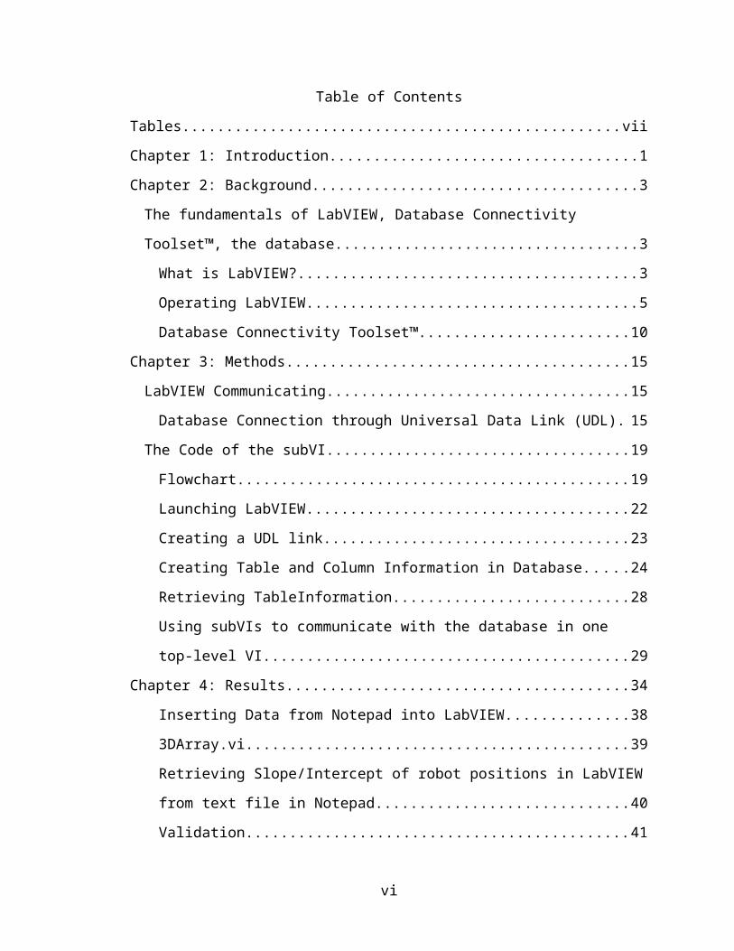
Table of Contents
Tables................................................................................................................................vii
Chapter 1: Introduction........................................................................................................1
Chapter 2: Background........................................................................................................3
The fundamentals of LabVIEW, Database Connectivity Toolset™, the database..........3
What is LabVIEW?......................................................................................................3
Operating LabVIEW....................................................................................................5
Database Connectivity Toolset™..............................................................................10
Chapter 3: Methods............................................................................................................15
LabVIEW Communicating............................................................................................15
Database Connection through Universal Data Link (UDL)......................................15
The Code of the subVI...................................................................................................19
Flowchart...................................................................................................................19
Launching LabVIEW.................................................................................................22
Creating a UDL link..................................................................................................23
Creating Table and Column Information in Database...............................................24
Retrieving TableInformation.....................................................................................28
Using subVIs to communicate with the database in one top-level VI.......................29
Chapter 4: Results..............................................................................................................34
Inserting Data from Notepad into LabVIEW............................................................38
3DArray.vi.................................................................................................................39
Retrieving Slope/Intercept of robot positions in LabVIEW from text file in Notepad
...................................................................................................................................40
Validation..................................................................................................................41
Inserting Calibration Information from LabVIEW....................................................41
Chapter 5: Discussion........................................................................................................45
Chapter 6: Conclusion.......................................................................................................46
Limitations and Future Endeavors.............................................................................46
References..........................................................................................................................47
Appendix............................................................................................................................48
vi
vii
TableTable 1 Definition of different ADO Object components.................................................14
vii
Figures
Figure 1: Text-based programming compared with LabVIEW’s source code. ..................4
Figure 2: Front panel and block diagram of VI...................................................................5
Figure 3: The 'Control' palette of the front panel.................................................................6
Figure 4: 'Function' palette in block diagram......................................................................8
Figure 5: Icon/connector example for a DB Tools Open Connection.vi.............................8
Figure 6: ODBC OLE DB Provider’s communication pathway between ADO and a
database..............................................................................................................................11
Figure 7: ADO and Access Database communicate using OLE DB Provider..................12
Figure 8: Hierarchy of the ADO object.............................................................................13
Figure 9: Creating a UDL on the Windows interface........................................................16
Figure 10: A connection to a database using UDL file path..............................................16
Figure 11: OLE DB Provider for UDL..............................................................................17
Figure 12: Connection to UDL..........................................................................................18
Figure 13: A simple create connection VI that opens a file through a UDL Link............19
Figure 14: Flowchart for Retrieve.vi..................................................................................20
Figure 15: Flowchart for List Create Delete.vi.................................................................21
Figure 16: LabVIEW icon for application link..................................................................22
Figure 17: LabVIEW startup screen. Right click on new to open new blank VI.............22
Figure 18: UDL Link between LabVIEW and a database.................................................23
Figure 19 : Source code of UDL.vi connection information between LabVIEW and
database..............................................................................................................................24
Figure 20: Empty table name in database (Create Table & Column.vi)...........................24
Figure 21: Need unique table name in database (Create Table & Column.vi)..................25
Figure 22: Column information in table put in database (Create Table & Column.vi).....25
Figure 23: Create table & column information in database (Create Table & Column.vi).26
Figure 24: Create table and column information in database (List Create Delete.vi).......26
Figure 25: Listbox of table names and column (List Create Delete.vi).............................27
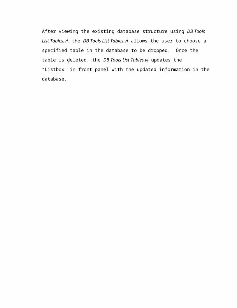
Figure 26: Delete table from database (List Create Delete.vi)..........................................27
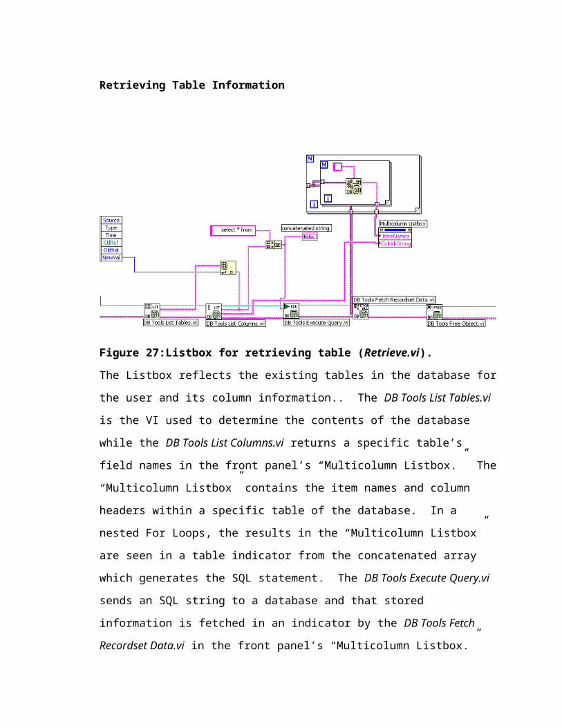
Figure 27:Listbox for retrieving table (Retrieve.vi)...........................................................28
Figure 28: Execute Query (Retrieve.vi).............................................................................29
viii
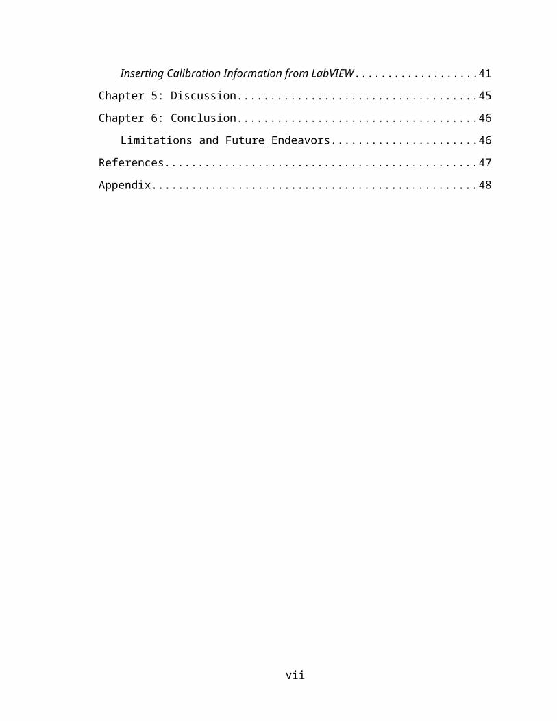
Figure 29: Communicating with Database.vi....................................................................30
Figure 30: UDL.vi (Communicating with Database.vi).....................................................31
Figure 31: Disabled List Create Delete.vi & Retrieve.vi (Communicating with
Database.vi).......................................................................................................................32
Figure 32: List Create Delete.vi (Communicating with Database.vi)...............................33
Figure 33: Retrieve.vi (Communicating with Database.vi)...............................................33
Figure 34: Communicating with Database.vi front panel and block diagram...................34
Figure 35: List Create Delete.vi front panel and block diagram.......................................35
Figure 36: Create Table & Column.vi...............................................................................36
Figure 37: Retrieve.vi's front panel and block diagram....................................................37
Figure 38: Data points in Notepad to be used for robot calibration..................................38
Figure 39: 3DArray.vi imports robot calibration data points from Notepad.....................39
Figure 40: SubVI Slopeintercept3DData.vi inputs slope and intercept for robot
calibration..........................................................................................................................40
Figure 41: Independent verification in Microsoft Excel to validate the slope and intercept
in LabVIEW’s subVI Slopeintercept3DData.vi................................................................41
Figure 42: Calibration Information in Database.vi...........................................................42
Figure 43: Information in Calibration Information in Database.vi..................................43
Figure 44: Calibration Information in Database.vi and the database...............................43
Figure 45: Slope and intercept information created in database using Calibration
Information in Database.vi................................................................................................44
ix
Chapter 1: Introduction
Knowledge is continuously changing and growing exponentially in the
technology rich twenty-first century. Tedious and labor-intensive assignments for the
average person and business have been markedly reduced by using robots and computers
to do the same work. Companies great and small have started using computer-controlled
robots to do dangerous and repetitious projects for humans.
Robots are most useful in executing the same defined job repeatedly and in
precisely the same fashion. When working on tasks that are continuously duplicated,
these automated machines are able to overcome certain types of errors better than
humans. Utilizing robots improves efficiency while lessening the likelihood for
inaccuracies in a procedure.5 In industry, specifically the pharmaceutical industry, the
higher throughput, greater reliability, and frequently far more cost-effectiveness attract
companies to use these machines on the job. Companies such as Eli Lilly (Indianapolis,
IN), a pharmaceutical corporation, utilize robots to do tedious and labor-intensive assays
using machines like the Beckman Coulter’s Biomek 2000™. Beckman Biomek is a robot
that can manipulate almost any type of liquid handling procedure. These procedures are
done quickly and more competently when compared to a human who is given the same
task. Some examples of liquid handling procedures are pipetting, diluting, and
dispensing. Biomek 2000 can pipette, move plates around, and do various types of
scientific assays that may take it a few hours, whereas a person doing the same task may
take days if not a month to accomplish. This automated robot allows the researcher to
have a less hands-on intervention concerning a particular repetitive and monotonous test,
and focus more on the implications of the results of an experiment. This moves the focal
point from just performing a tedious experiment and instead allows for researchers to
focus more on understanding the overall picture of the data. This is one big reason that
laboratory automation is very attractive to pharmaceutical corporations.
Another corporation, the Hershey Company (Hershey, Pennsylvania) utilized a
specific robot to prepare chocolate formulation. The robot used was a Caliper Life
Sciences (Hopkinton, MA) Zymate XP™. Hershey decided to contribute to the research
potential of laboratory robots by donating one of its Zymark robots to the School of
1
Informatics for the Laboratory Informatics Graduate Program at Indiana University-
Purdue University Indianapolis (IUPUI). This robot is used in a course, INFO I510 Data
Acquisition and Laboratory Automation. It is a good tool to demonstrate the
fundamentals of laboratory robotics. This robot has been re-engineered to function with
National Instruments™ (Austin, Texas) graphical software program, LabVIEW™
(Laboratory Virtual Instrument Engineering Workbench).
LabVIEW is an excellent tool for robotic control. This software is able to use
data from various sources to modify the automation’s operating parameters. The robot
user needs to quickly access and store any and all of this dynamically changing
information. For example, there is a need to continuously store and update the calibration
data of the robot, populate the setting of each axis and positioning inside the workplace,
and also store robot positioning information. The solution to this problem was to create a
database that will allow for robotic control data to be easily searched and accessed.
LabVIEW’s front panel became the interface that allowed complete dynamic
communication between its various Virtual Instruments (VIs, LabVIEW’s program) and
the database that was formed. This was carried out by developing a set of subVIs (which
will be explained later) that were dropped into the calling robotic control VIs. With these
subVIs, the user has the facilities needed to create table and column information, delete a
table, retrieve table information by clicking a particular table name on the user interface
or query using Structured Query Language (SQL) any specific combination of columns
or tables within the database. For robot functionality, a subVI was created for insertion
of data into a database. Calibration information for the robot, including line values like
slope and intercept, are now saved in a database.
2
Chapter 2: Background
The fundamentals of LabVIEW, Database Connectivity Toolset™, the database
This chapter focuses on defining key concepts such as what LabVIEW™ is and
the fundamental concepts of database interactions by the LabVIEW Database
Connectivity Toolset™ (DCT).
What is LabVIEW?
LabVIEW is an acronym for Laboratory Virtual Instrument Engineering
Workbench. It is a computer software development application created by National
Instruments™ (Austin, Texas) that aims to aid scientists and researchers in gathering and
understanding data using computer programs. LabVIEW is a G graphical programming
software that utilizes graphical objects to symbolize lines of code instead of the average
programmers’ text-based languages. In the source code of this graphical program, data
execution depends on the flow of data. What may take days in C++ or Java written code
is cut down to hours in G programming. Add to this, LabVIEW has built a general
purpose library of functions and subroutines for most programming tasks. The time
saved allows the user to fully focus and understand how data is flowing. Even though
some type of programming experience is useful, a novice in text-based programming
language(s) can grasp the mechanics of LabVIEW because it is a graphical programming
language utilizing iconic symbols to illustrate program action.
3
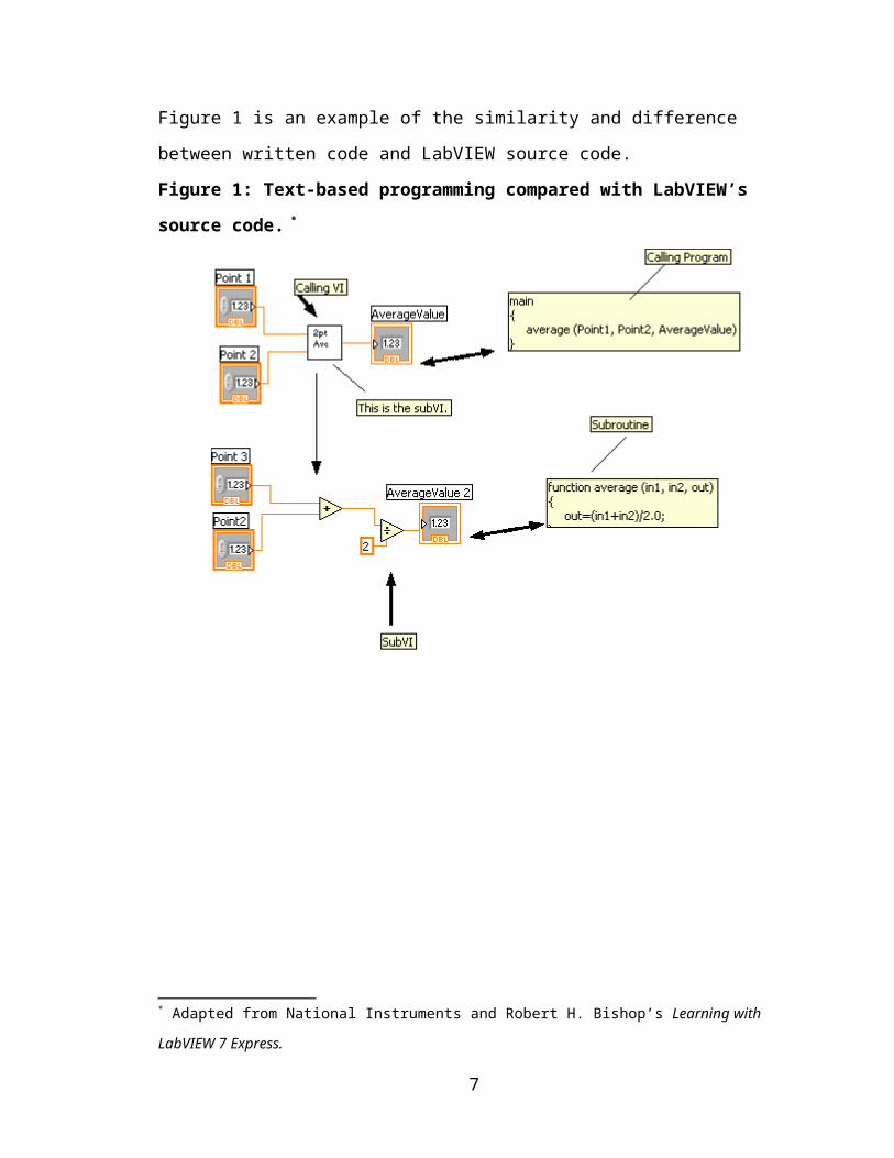
Figure 1 is an example of the similarity and difference between written code and
LabVIEW source code.
Figure 1: Text-based programming compared with LabVIEW’s source code. *
* Adapted from National Instruments and Robert H. Bishop’s Learning with LabVIEW 7 Express.
4
Operating LabVIEW
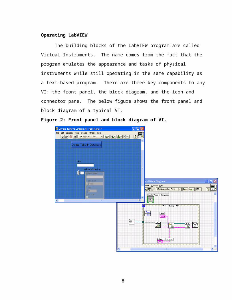
The building blocks of the LabVIEW program are called Virtual Instruments.
The name comes from the fact that the program emulates the appearance and tasks of
physical instruments while still operating in the same capability as a text-based program.
There are three key components to any VI: the front panel, the block diagram, and the
icon and connector pane. The below figure shows the front panel and block diagram of a
typical VI.
Figure 2: Front panel and block diagram of VI.
Front Panel
The front panel is the VI’s interactive interface built with controls (inputs) and
indicators (outputs) that replicate conventional instruments, like thermostats or knobs, as
may be found in the real world.
5
The controls that are built on the front panel are wide-ranging as seen in the ‘Control’
tool palette in Figure 3.
Figure 3: The 'Control' palette of the front panel.
Using the mouse and keyboard, the LabVIEW programmer grabs and drops the input data
onto the interface panel.
6
Block diagram
The block diagram is the source code location for executing programs in
LabVIEW and is equivalent to text-based programming such as C++. The block diagram
has three central parts to its source code: nodes, wires, and terminals. This is the site
where the wiring of graphical objects or terminals is connected to the functional nodes.
Terminals are the controls (inputs) and indicators (outputs) of the block diagram. When
compared with written source code, nodes are equal to statements, functions, and
subroutines. An example of a node may be an addition function or a while loop. The
addition function is considered a lower-level VI. It is part of the general purpose
LabVIEW library of functions and subroutines for programming tasks. Execution of the
program, with all three—nodes, terminals, and wires—can occur when wiring between
the terminals and nodes has been connected to designate the flow of data. The terminals
in the front panel have parallel terminals on the block diagram; thereby data continuously
flows from the interface in the front panel to the source code in the block diagram and
back to the interface. Figure 4 illustrates the ‘Function’ palette in the block diagram.
Some subpalettes like ‘Database’ are subVIs which are used to perform subroutines like
opening, closing, or inserting a database.
7
Figure 4: 'Function' palette in block diagram.
Icon/Connector
An icon symbolizes a VI in another block diagram. When an icon is placed in a
foreign block diagram, it is there to act as a subroutine. A VI within another VI is called
a subVI and is considered a lower-level call. A subVI connects with a top-level VI by
means of a connector that passes data to outputs/indicators in the block diagram and
receives data from inputs/controls in the front panel of the lower call terminal. The icon
is the graphical representation of the subVI and may be likened to constraints of a
subroutine in written code. To function as a subtask in a top-level call, there must be an
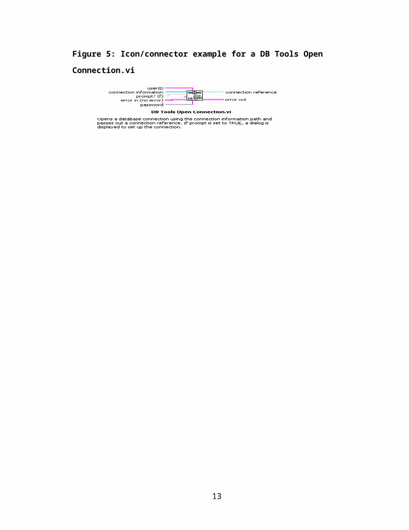
icon and a connector as seen in Figure 5.
Figure 5: Icon/connector example for a DB Tools Open Connection.vi
8
The LabVIEW graphical program is both hierarchical and modular. Top-level
and low-level calls, such as routines within a subroutine, are examples of this program’s
hierarchical nature. Each subroutine, or subVI, can execute independently of the top-
level VI. A subVI can be built upon other subVIs. For example, a programmer creates a
VI, titled “List.vi,” which lists all tables currently existing in a database. If a user wants
to create a new table, then a VI, titled “Create.vi” for creating new table name(s) and
column information(s) is built. To view if this new table has been created in the
database, “Create.vi” is inserted into the block diagram, or program source code of
“List.vi.” The “Create.vi” has now become a subVI of “List.vi.”
9
Database Connectivity Toolset™
For the purpose of this project, the application program utilized with the
LabVIEW Database Connectivity Toolset™ (DCT) is Microsoft Access Relational
Database Management System for Windows. One can incorporate Structured Query
Language (SQL) in addiction to the DCT’s Virtual Instruments found in the ‘Function’
palette.
Database Basics
The basic concept of the database is the organization of acquired data. The Jet
database engine of MS Access is its Database Management System (DBMS). MS Access
stores acquired data in tables. The tables are made up of record sets which consist of
rows and fields (also known as columns). Each table must be uniquely named. A row
may have empty cells or SQL NULL values.
The database table can offer useful features for the average user. Utilizing the
SELECT statement of the SQL query, one can sort, group, and modify data.
Database Connectivity Toolset
The LabVIEW Database Connectivity Toolset is owned by National Instruments.
It originated from an older toolkit known as the SQL Toolkit created from a code of
interface node (CIN) that links to a chain of Dynamic Link Libraries (DLLs). “These
DLLs made system calls into Microsoft’s application programming interface (API) for
database access called ODBC.”1
ODBC, UDA, OLE DB, and ADO
The Open Database Connectivity (ODBC) was created by many entities (SQL
Access Group, Microsoft, Tandem, Oracle, Informix, and Digital Equipment
Corporations), as the standard form to access databases.1 The major drawback of ODBC
is that it works only on relational databases. Microsoft saw the potential in creating a
standard format that accesses both relational and non-relational databases and thereby
created Universal Data Access (UDA) which links various data types from any
application or data stores. Object Linking and Embedding Database (OLE DB)
10
implements UDA. ActiveX Data Objects (ADO) is the application-level programming
layer between the program language and the database. Because of this, a user can garner
data with programs one writes without necessarily understanding the implementation of
the database. UDA is executed by Microsoft Data Access Components (MDAC) which
includes ODBC, OLE DB, and ADO. MDAC installs many types of data providers that
create an open connection to a particular data source.1 In LabVIEW, MDAC
automatically installs with the installation of Database Connectivity Toolset. The current
version installed is MDAC 2.5.
OLE DB
OLE DB and ADO are founded on Microsoft’s object-oriented programming
model Component Object Model (COM) that identifies object communication within a
single application or between applications. This basically means that despite the type of
programming language, COM can initiate one’s application as long as its Microsoft’s
ADO or OLE DB. There are many types of COM components: OLE DB Data Providers,
OLE DB Consumers, and OLE DB Service Providers.1 For this project, the COM
component type used is OLE DB Data Providers. This type of COM is “data source-
specific software layers that are responsible for accessing and exposing data.”1
Figure 6: ODBC OLE DB Provider’s communication pathway between ADO and a
database.*
* Adapted from Database Connectivity Toolset Manual
11
OLE DB Provider for Jet
MDAC allows for a native provider for Jet database systems. Native drivers
perform more efficiently than the OLE DB Provider for ODBC because it oversteps the
unnecessary need for “OLE DB to ODBC conversion process and for the ODBC driver
and Driver Manager layers.”1 This is the reason that a native OLE DB data provider for
the data source was employed when accessing data.
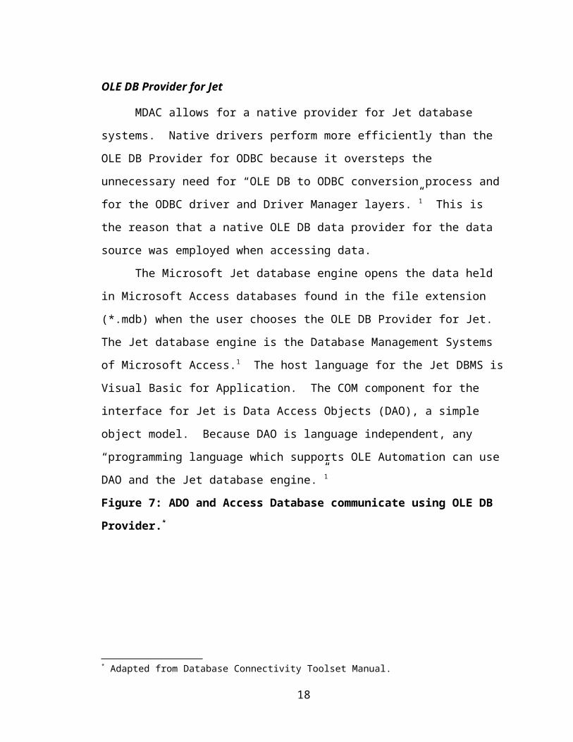
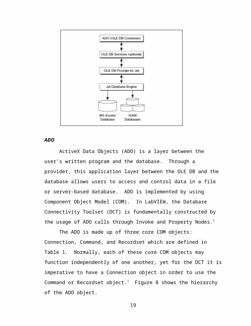
The Microsoft Jet database engine opens the data held in Microsoft Access
databases found in the file extension (*.mdb) when the user chooses the OLE DB
Provider for Jet. The Jet database engine is the Database Management Systems of
Microsoft Access.1 The host language for the Jet DBMS is Visual Basic for Application.
The COM component for the interface for Jet is Data Access Objects (DAO), a simple
object model. Because DAO is language independent, any “programming language
which supports OLE Automation can use DAO and the Jet database engine.”1
Figure 7: ADO and Access Database communicate using OLE DB Provider.*
ADO
ActiveX Data Objects (ADO) is a layer between the user’s written program and
the database. Through a provider, this application layer between the OLE DB and the
* Adapted from Database Connectivity Toolset Manual.
12
database allows users to access and control data in a file or server-based database. ADO
is implemented by using Component Object Model (COM). In LabVIEW, the Database
Connectivity Toolset (DCT) is fundamentally constructed by the usage of ADO calls
through Invoke and Property Nodes.1
The ADO is made up of three core COM objects: Connection, Command, and
Recordset which are defined in Table 1. Normally, each of these core COM objects may
function independently of one another, yet for the DCT it is imperative to have a
Connection object in order to use the Command or Recordset object.1 Figure 8 shows the
hierarchy of the ADO object.
Figure 8: Hierarchy of the ADO object.*
.
* Adapted from Database Connectivity Toolset Manual.
13
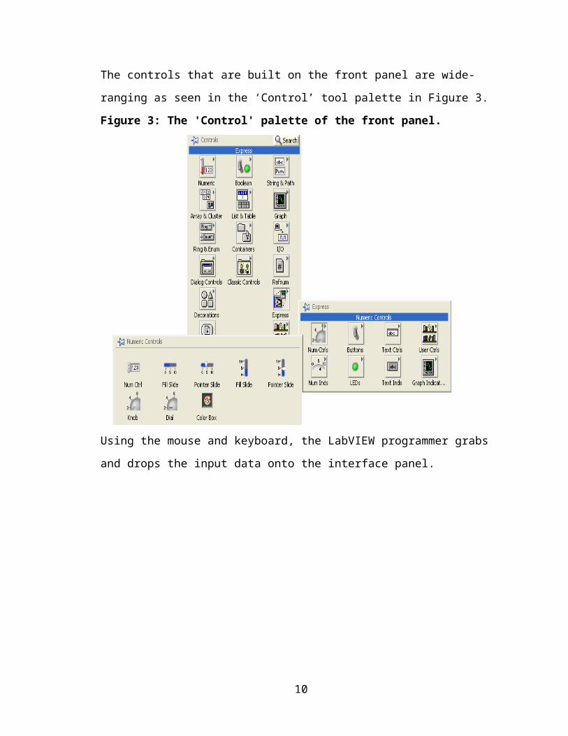
Table 1 Definition of different ADO Object components*
Components Description
Connection This object represents an open connection to an
OLE DB data source. IT contains methods for
setting timeouts and maintaining information about
the connection.
Command The two major uses for a command object are to
execute statement against an OLE DB connection
and to retrieve a recordset based on an SQL query
or stored procedure.
Recordset This object represents a set of records and is used to
manipulate data in a data source. You also can
control cursors and the locking types for recordsets.
Record This object represents a single row in a recordset.
The Record, Stream, and Recordset objects work
together to help you navigate through data.
Stream This object represents binary data, usually stored in
Unicode.
Property This object is the building block of the other ADO
objects. The properties collection contains only the
properties added to the object by the data provider
and does not contain the intrinsic properties of the
object.
Error This object represents a single error.
Parameter This object represents a single parameter for a
Command object. Generally, parameters are used
with any type of parameterized commands where an
action is defined once but can have results changed
depending on the variable values.
Field This object represents a single column of data in a
recordset. The fields collection is the default
property of the Recordset object, so you do not
often see its name in the code.
* Adapted the Database Connectivity Toolset Manual
Chapter 3: Methods
LabVIEW Communicating
This chapter explains the implementation process to connect the database to
LabVIEW™. The discussion starts with the methods utilized to connect to a database
while giving examples of the technical VIs for creating, inserting, and deleting data.
Database Connection through Universal Data Link (UDL)
It is very important to have a connection to the database before any type of
creation or modification can be processed. The different level of security and parameters
are determined by the database management system (DBMS). “ODBC uses Data Source
Name (DSN) for the connection and ADO uses Universal Data Links (UDL) for the
connection.”1 This project uses ADO. Creating data links in Windows is not accessible
to the user unless Database Connectivity Toolset builds data links by registering UDL
files in the Windows registry.1 After the UDL files are registered in Windows, the user
can right click on the Desktop and find Microsoft Data Link as shown in the below
figure. For this project, Universal Data Links are used for connecting LabVIEW to the
database.
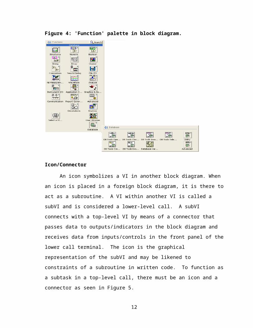
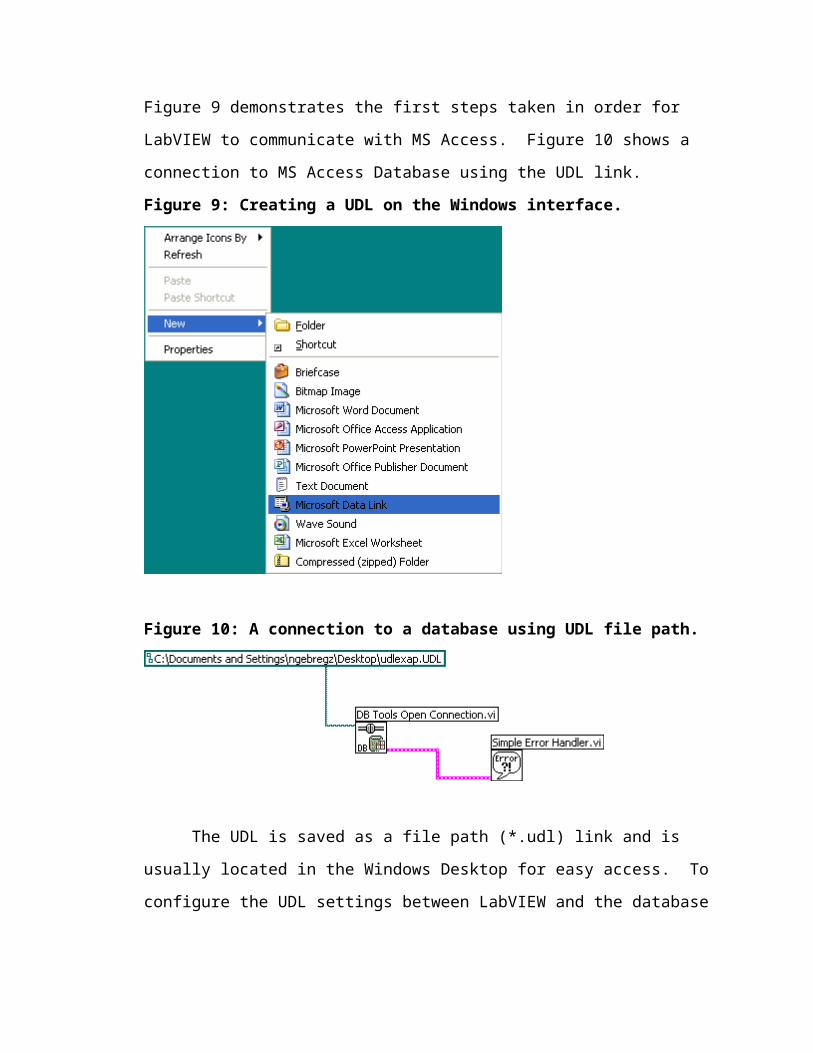
Figure 9 demonstrates the first steps taken in order for LabVIEW to communicate with
MS Access. Figure 10 shows a connection to MS Access Database using the UDL link.
Figure 9: Creating a UDL on the Windows interface.
Figure 10: A connection to a database using UDL file path.
The UDL is saved as a file path (*.udl) link and is usually located in the Windows
Desktop for easy access. To configure the UDL settings between LabVIEW and the
database for the file path, one can double click on the Windows interface and choose the
Microsoft Data Link property.
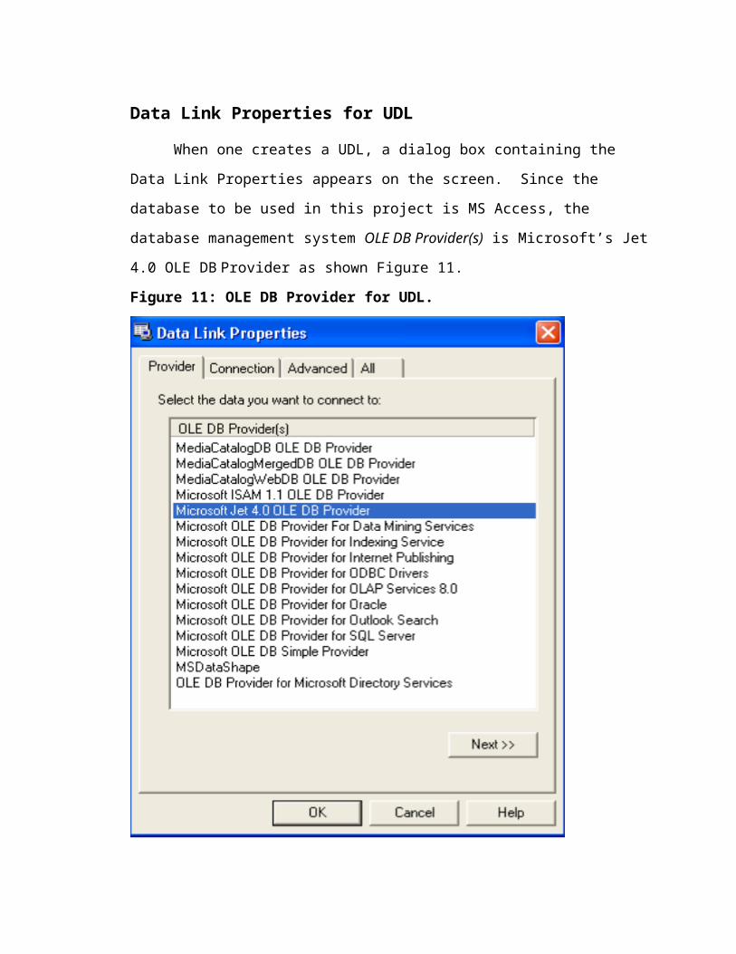
Data Link Properties for UDL
When one creates a UDL, a dialog box containing the Data Link Properties
appears on the screen. Since the database to be used in this project is MS Access, the
database management system OLE DB Provider(s) is Microsoft’s Jet 4.0 OLE DB
Provider as shown Figure 11.
Figure 11: OLE DB Provider for UDL.
Once OLE DB Provider has been configured, the user then defines the connection
to the specific database using the Connection tab on the Data Link Properties.
Figure 12: Connection to UDL
The Test Connection is then pressed to confirm that the connection is valid and error free.
Figure 13 illustrates how one can use a UDL link to connect to a particular database.
Figure 13: A simple create connection VI that opens a file through a UDL Link.
The Code of the subVI
For this project, LabVIEW Database Connectivity Toolset v1.0 was used to
communicate between MS Access and LabVIEW. Prior to graphically programming the
code, a flowchart was used to determine any troubles the user may encounter while
running the program. The flowchart was also useful for getting an overall picture of how
the top-level VI structure and subVI will integrate together.
Flowchart
The flowchart below represents the thought process for implementing the VI that
List Create Delete.vi and Retrieve.vi into the top-level call Communicating with
Database.vi.
Figure 14: Flowchart for Retrieve.vi
Start
Initialize Communicating with Database.vi & Prompt UDL link-Disable List Create Delete.vi and Retrieve.vi
Enable List Create Delete.vi and Retrieve.vi
Retrieve.vi
List Create Delete.vi
Open VI
Initialize show table names in Listbox
Select table from Listbox
Stop/Close VI
SQL Execution
Get Input Data for table name/column information
Error Checking/shows sequel statement
Show column information of table in Listbox
Error Prompt: Correct column(s)/ table name
Check if empty UDL
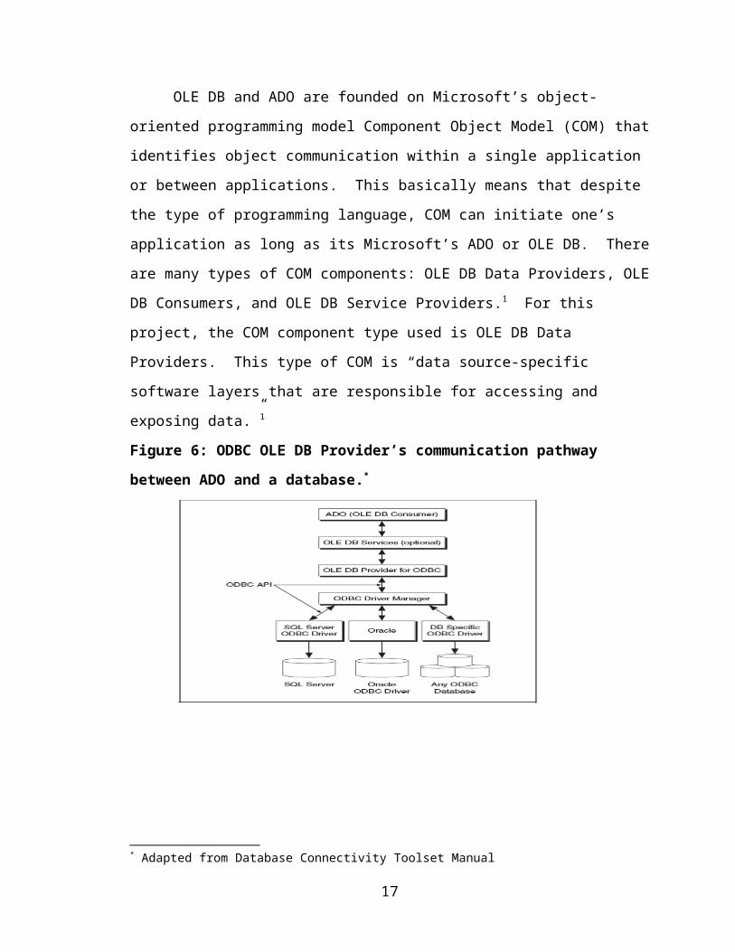
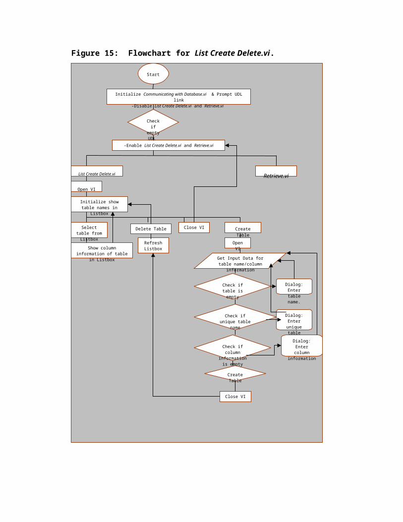
Figure 15: Flowchart for List Create Delete.vi.
Start
Initialize Communicating with Database.vi & Prompt UDL link-Disable List Create Delete.vi and Retrieve.vi
-Enable List Create Delete.vi and Retrieve.vi
List Create Delete.vi Retrieve.vi
Open VI
Initialize show table names in Listbox
Select table from Listbox
Delete Table Close VI Create Table
Open VI
Get Input Data for table name/column information
Show column information of table in Listbox
Refresh Listbox
Check if table is empty
Dialog: Enter table name.
Check if unique table name
Dialog: Enter unique table
name.
Check if column information is
empty
Dialog: Enter column
information
Create Table
Close VI
Check if empty UDL
Launching LabVIEW
1. Launch LabVIEW with application icon link as seen below.
Figure 16: LabVIEW icon for application link.
Labview.lnk
2. A dialog box appears with the start up screen.
Figure 17: LabVIEW startup screen. Right click on new to open new blank VI.
Creating a UDL link
1. The UDL link was the first VI created so there was always an available connection
between LabVIEW and the database.
Figure 18: UDL Link between LabVIEW and a database.
2. The front panel had only two terminals: an empty UDL path file input labeled
‘Connection Information’ and an ‘Ok’ button. The user would be able to access the file
path by clicking the file folder image to the right of the empty UDL path file.
3. The block diagram has three terminals and five nodes. The three terminals are input,
output, and an ‘OK’ button. The five nodes are while loop, event structure, case
structure, equal function, and a stop constant inside the event structure. In the event that
the user wants to open a UDL link, an input terminal to enter file path is available in an
event structure node. In case (using the case structure node) the user left the ‘Column
Information’ box blank, a dialog box will appear requesting: “Please enter link to UDL.”
The user is then looped back into the event structure to enter a file path. If file path is
entered, the user can click the ‘OK’ button and UDL.vi closes automatically. Closing the
UDL.vi automatically is an option that the programmer can make for the user as a
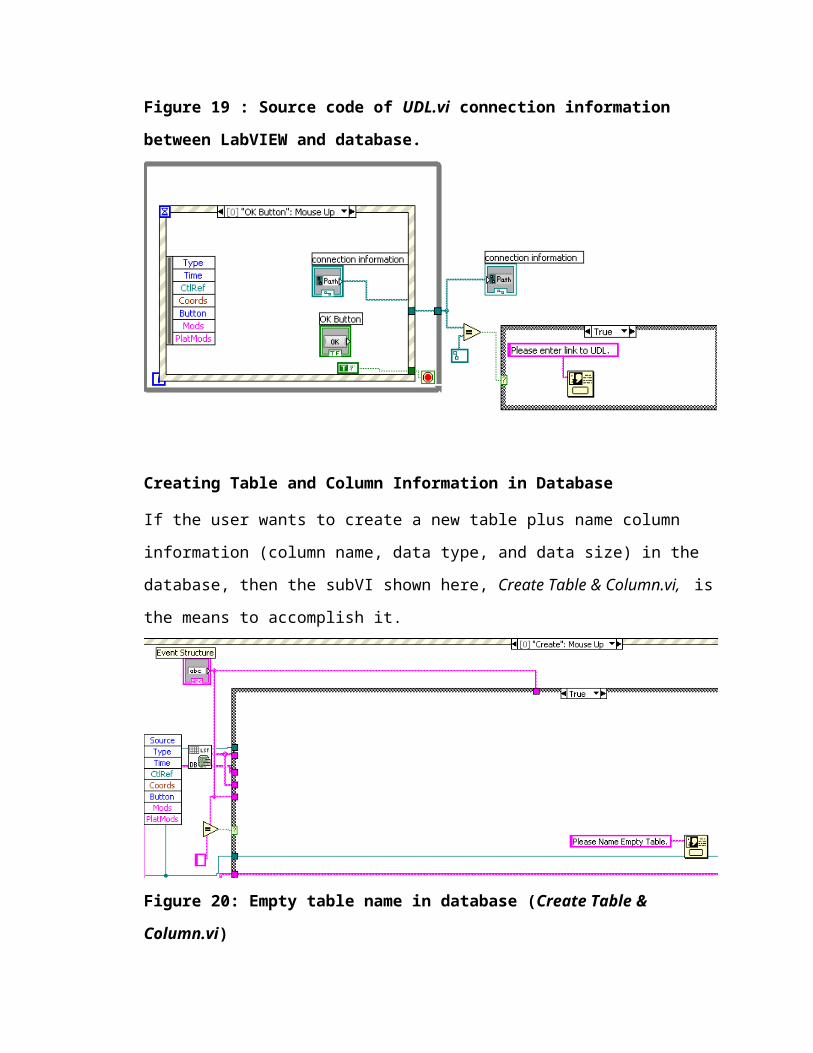
Window Appearance of a VI property. Figure 19 shows the source code of UDL.vi. In
this project, UDL.vi is the connection reference which will be identified by all other VIs
that call this lower-level VI.
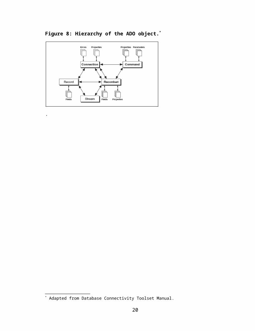
Figure 19 : Source code of UDL.vi connection information between LabVIEW and
database.
Creating Table and Column Information in Database
If the user wants to create a new table plus name column information (column name, data
type, and data size) in the database, then the subVI shown here, Create Table &
Column.vi, is the means to accomplish it.
Figure 20: Empty table name in database (Create Table & Column.vi)
In this VI, the user is able to see all the tables that exist using the DB Tools List Tables.vi.
If the table is found to be empty, then a dialog box appears requesting: “Please Name
Empty Table.”
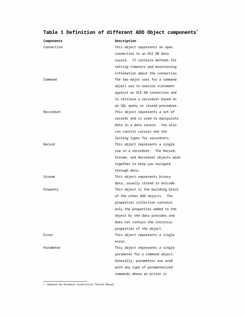
Figure 21: Need unique table name in database (Create Table & Column.vi)
In this VI, the user is able to see all the tables that exist using the DB Tools List Tables.vi.
If the table is found to not be a unique table name, then a dialog box appears requesting:
“Table name already exists. Rename table.”
Figure 22: Column information in table put in database (Create Table & Column.vi).
In this VI, the user is able to see all the tables that exist using the DB Tools List Tables.vi.
If the column information is left empty by user, then a dialog box appears requesting:
“Please fill out column information:Column Name, Data type, Size.”
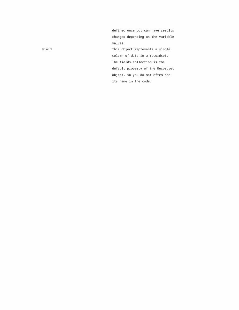
Figure 23: Create table & column information in database (Create Table &
Column.vi).
If the user has entered a unique table name and filled the column information box, then
the DB Tools Create Table.vi is used to create the table and column information in the
database. It lists all tables (including column information), creates new tables, and deletes
specific tables from the database
Figure 24: Create table and column information in database (List Create Delete.vi)
The above picture demonstrates how Create Table & Column.vi is used as a subVI of the
higher call VI List Create Delete.vi. The DB Tools List Tables.vi refreshes the “Listbox”
in the front panel with all the new tables (also known as the item names) as it is added to
the database. The new data from Create Table & Column.vi is stored into a particular
database that is shown in the “Listbox” of the front panel’s List Create Delete.vi.
Meanwhile, DB Tools List Tables.vi that is connected to the Create Table & Column.vi
refreshes the “Listbox” in the front panel as new table names are added to the database.
Figure 25: Listbox of table names and column (List Create Delete.vi)
The tables and column information (column names, data type-string, binary, etc.-, data
sizes)are viewed by the user in the front panel’s “Multicolumn Listbox.” The DB Tools
List Table.vi specifies what tables exist in a database. Using an Index Array function
connected to DB Tools List Columns.vi, a list of all the column information is shown in
“Multicolumn Listbox.”
Figure 26: Delete table from database (List Create Delete.vi).
After viewing the existing database structure using DB Tools List Tables.vi, the DB Tools
List Tables.vi allows the user to choose a specified table in the database to be dropped.
Once the table is deleted, the DB Tools List Tables.vi updates the “Listbox” in front panel
with the updated information in the database.
Retrieving Table Information
Figure 27:Listbox for retrieving table (Retrieve.vi).
The Listbox reflects the existing tables in the database for the user and its column
information.. The DB Tools List Tables.vi is the VI used to determine the contents of the
database while the DB Tools List Columns.vi returns a specific table’s field names in the
front panel’s “Multicolumn Listbox.” The “Multicolumn Listbox” contains the item
names and column headers within a specific table of the database. In a nested For Loops,
the results in the “Multicolumn Listbox” are seen in a table indicator from the
concatenated array which generates the SQL statement. The DB Tools Execute Query.vi
sends an SQL string to a database and that stored information is fetched in an indicator by
the DB Tools Fetch Recordset Data.vi in the front panel’s “Multicolumn Listbox.” The
DB Tools Free Object.vi destroys any associated ADO Command object connection
reference (the execution of the stored procedure) and frees itself to be connected to a
different reference that allows the VI to be closed.

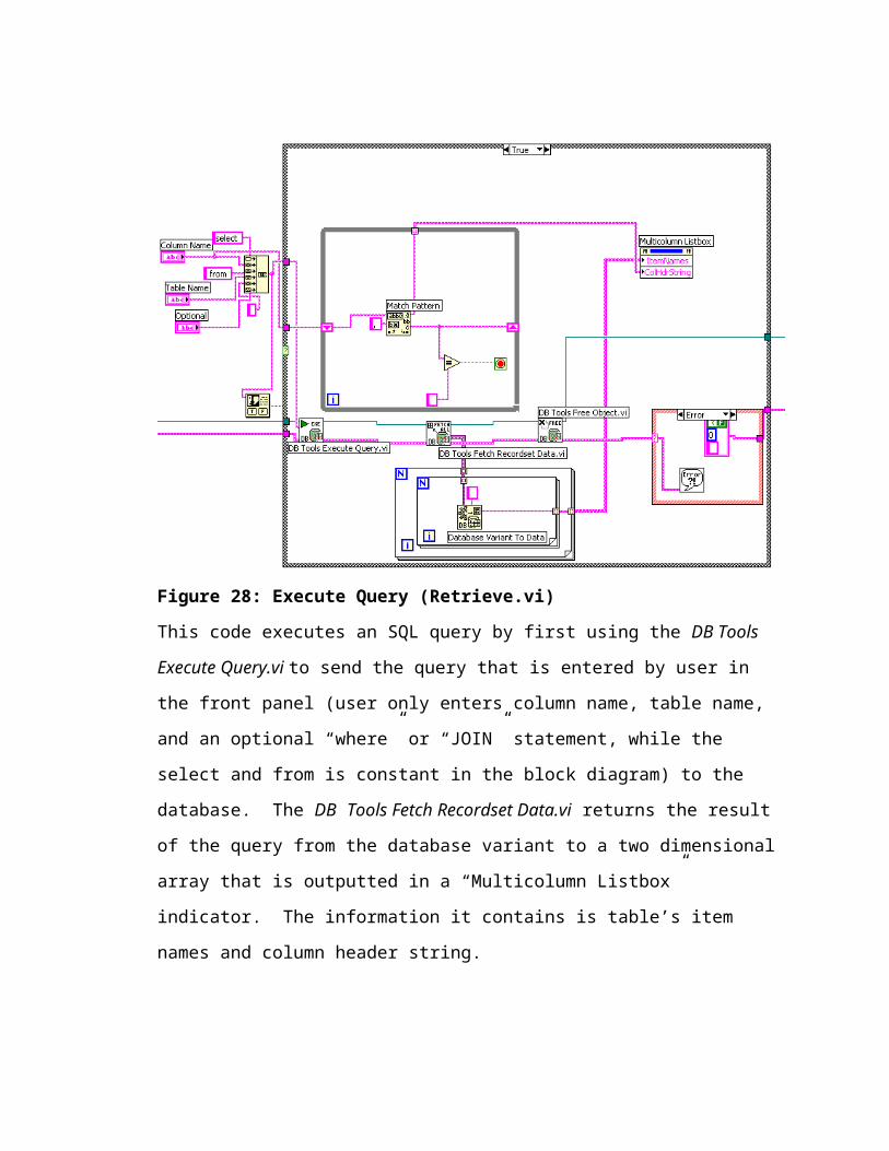
Figure 28: Execute Query (Retrieve.vi)
This code executes an SQL query by first using the DB Tools Execute Query.vi to send
the query that is entered by user in the front panel (user only enters column name, table
name, and an optional “where” or “JOIN” statement, while the select and from is constant
in the block diagram) to the database. The DB Tools Fetch Recordset Data.vi returns the
result of the query from the database variant to a two dimensional array that is outputted
in a “Multicolumn Listbox” indicator. The information it contains is table’s item names
and column header string.
Using subVIs to communicate with the database in one top-level VI
Communicating with Database.vi is the top-level VI that calls the lower level
subVIs: UDL.vi, List Create Delete.vi, and Retrieve.vi. Communicating with Database.vi
gives the user many options of interacting with database. Using LabVIEW’s front panel
as the interface, user creates new tables and column information into the database with
List Create Delete.vi. In the subVI, user can use the Window’s mouse to highlight a table
name and delete it from the database. The client also has the option of retrieving stored
data from the database through the Retrieve.vi. User may even query with SQL for
special types of operations, such as comparing two tables simultaneously with afore
mentioned subVI. All of these user preferences are derived from the top-level VI,
Communicating with Database.vi. The top-level VI first calls the UDL link, while
disabling the ability for user to use Retrieve.vi or Liste Create Delete.vi. The second
sequence allows user to enable Retrieve.vi and List Create Delete.vi after UDL has been
linked. The sequence executed in event structures depends on user preference.
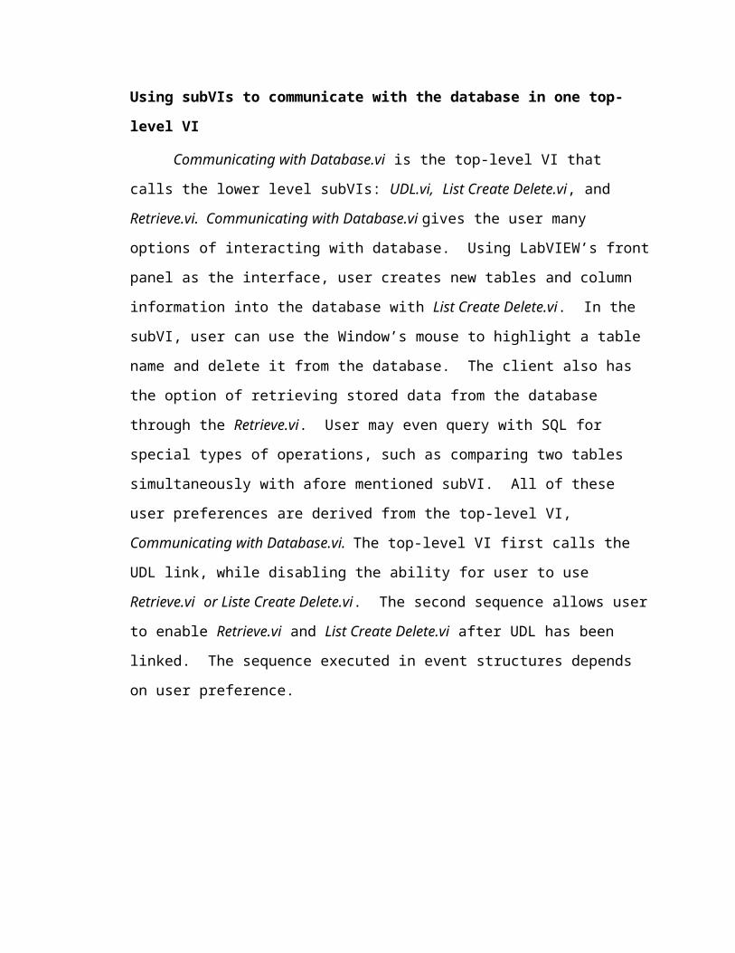
Figure 29: Communicating with Database.vi
The top-level VI, Communicating with Database.vi, exemplifies communication between
LabVIEW and a database (MS Access). This communication is used for creating new
tables in the database, retrieving contents in from that table, deleting a table, and listing
existing tables in the database.
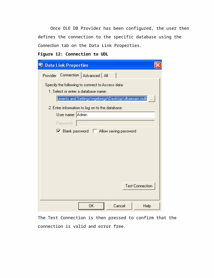
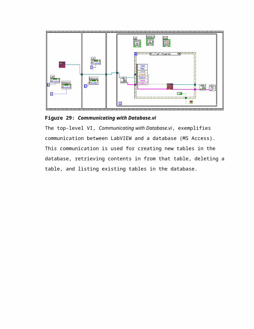
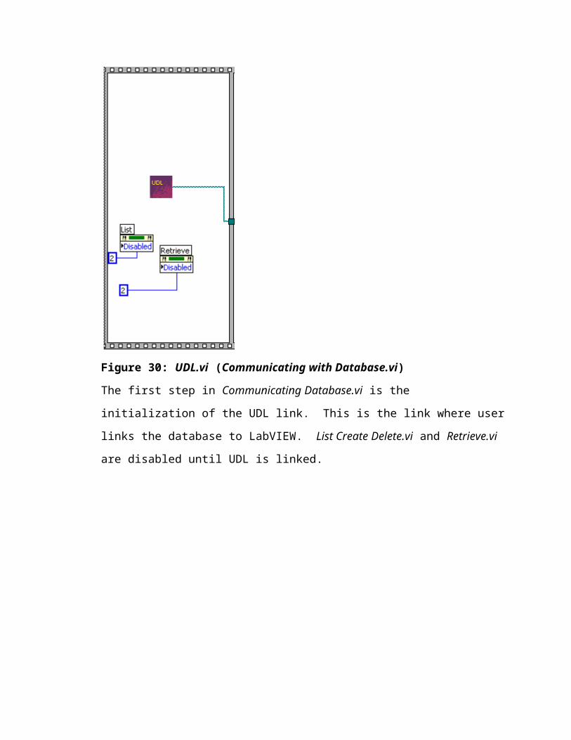
Figure 30: UDL.vi (Communicating with Database.vi)
The first step in Communicating Database.vi is the initialization of the UDL link. This is
the link where user links the database to LabVIEW. List Create Delete.vi and Retrieve.vi
are disabled until UDL is linked.
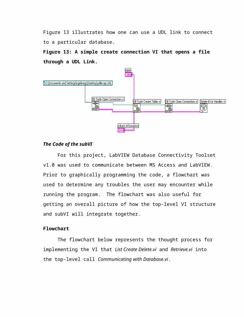
Figure 31: Disabled List Create Delete.vi & Retrieve.vi (Communicating with
Database.vi)
After the UDL is linked, then List Create Delete.vi and Retrieve.vi are enabled for user to
interact with the database. The zero in the ‘Disabled’ property node represents the
enabling of the VI, the one represents disabling the VI, while the two represents disabling
and graying out the VI.
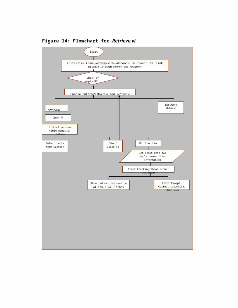
Figure 32: List Create Delete.vi (Communicating with Database.vi)
The List Create Delete.vi is a subVI in the Communicating with Database.vi which may
be opened if user clicks it.
Figure 33: Retrieve.vi (Communicating with Database.vi)
The Retrieve.vi is a subVI in the Communicating with Database.vi which may be opened
if user clicks it.
Chapter 4: Results
Figure 34: Communicating with Database.vi front panel and block diagram.
This top level VI is made up of many subVIs within subVIs. In the above figure, the
subVIs are Retrieve.vi , List Create Delete.vi, and UDL.vi. There is an unseen subVI icon
of Create Final.vi (also known as Create Table & Column.vi) that is part of this calling
VI..
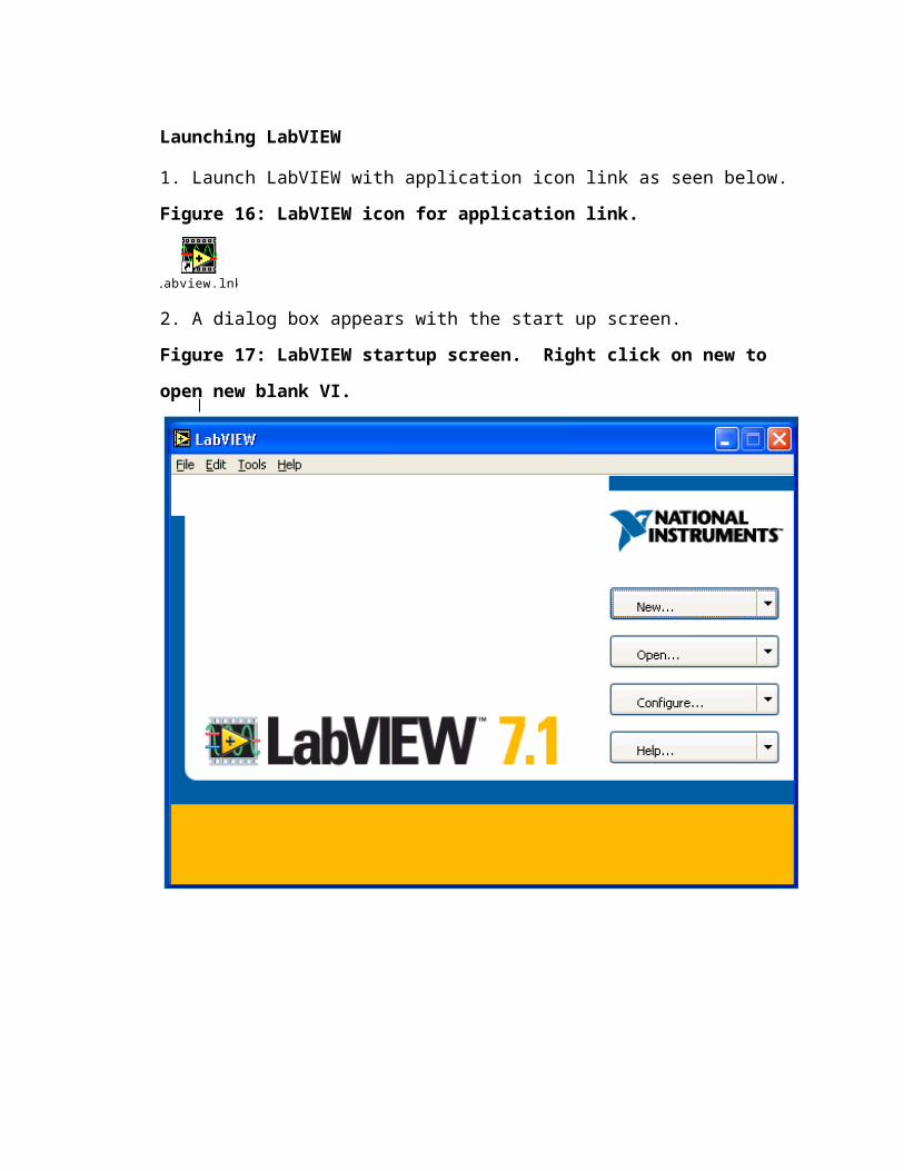
Figure 35: List Create Delete.vi front panel and block diagram.
(subVIicon/connector)
This VI lists all tables in database, while at the same time the subVI has the capacity to
create new table(s) or delete existing table(s) in Listbox. (These VIs, especially the block
diagram can be seen fully if printed as Landscape.)
Figure 36: Create Table & Column.vi.
(subVI icon/connector)
This subVI with its front panel and block diagram allows user to create new table and
column information. (These VIs, especially the block diagram can be seen fully if
printed as Landscape.)
Figure 37: Retrieve.vi's front panel and block diagram.
(subVI icon/connector)
These allow user to retrieve all data in database by clicking a table name in Listbox of
Tables and seeing the results in front panel icon labeled “The Table's Multicolumn
Listbox”. (These VIs, especially the block diagram can be seen fully if printed as
Landscape.)
Inserting Data from Notepad into LabVIEW
All data points which had been gathered in Notepad, as seen in Figure 38, for
robot calibration were imported into LabVIEW as a subVI. This subVI, 3DArray.vi, has
been used in a top-level VI, Inserting Calibration Data from Notepad &
Slope/Intercept.vi, to insert these same data points into MS Access for easier storage and
data retrieval.
Figure 38: Data points in Notepad to be used for robot calibration.

3DArray.vi
When the subVI 3DArray.vi is executed, the block diagram utilizes advanced file
functions from the ‘Function’ palette to open a dialog box for user to specify an existing
file path.2 From there, data flows through another ‘Functions’ palette icon that reads
characters from the file before sending it to be converted from spreadsheet string
(because the data points in Notepad were delimited by tabs) into an array of strings. The
user defines the conversion of the string into an array by an icon for formatting string in
the ‘Function’ palette. After the conversion, the data indicator in front panel reflects the
results as an array of strings.
Figure 39: 3DArray.vi imports robot calibration data points from Notepad.

Retrieving Slope/Intercept of robot positions in LabVIEW from text file in Notepad
When the subVI Slopeintercept3DData.vi is executed, a dialog box opens to
specify a file path chosen by the user to be read by the program. The ‘Function’ palette
Read From Spreadsheet File.vi has the subVI Read Characters From File.vi that was
used to import the data points from Notepad. The data numbers from the text file were
converted into a 2D, single-precision array. The array was then indexed from the text file
at column 2 and column 1 for the slope and intercept. The first column in Figure 38 is
column 0, column 1, column 2, etc. The VI Linear Fit.vi from the ‘Function’ palette was
used for finding line values before being ‘bundled by name’ so that slope and intercept
are distinguished in the cluster output.
Figure 40: SubVI Slopeintercept3DData.vi inputs slope and intercept for robot
calibration.
Validation
To make sure that the slope and intercept indicated by LabVIEW in Figure 40
were valid, Microsoft Excel was used to independently verify if the same slope and
intercept answers appeared from the Figure 38 text in Notepad. It can be noted that
LabVIEW’s subVI Slopeintercept3DData.vi , seen in Figure 40, is the same slope and
intercept answer as Microsoft Excel. This reflects the validity of the subVI.
Figure 41: Independent verification in Microsoft Excel to validate the slope and
intercept in LabVIEW’s subVI Slopeintercept3DData.vi.
Inserting Calibration Information from LabVIEW
The user can insert the data gathered in the VIs, 3DArray.vi and
Slopeintercept3DData.vi, into the MS Access database. By using the icon/connector to
make the above two subVIs, the new graphical objects can be ‘dropped’ from the lower-
level VI to top-level VI Inserting Calibration Data from Notepad & Slope/intercept.vi.
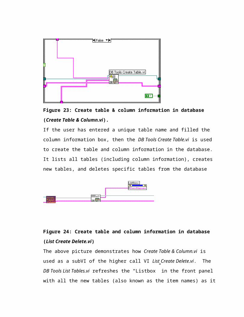
Figure 42: Calibration Information in Database.vi.
Calibration Information in Database.vi takes data from the 3DArray.vi and
Slopeintercept3DData.vi and inserts it into a database. The user is able to use the
‘Function’ mode to create the column names and than insert the data from subVI
3DArray.vi.
Figure 43: Information in Calibration Information in Database.vi.
Figure 44: Calibration Information in Database.vi and the database.
Calibration Information in Database.vi takes data from the 3DArray.vi and
Slopeintercept3DData.vi and inserts it into a database. The user is able to use the
‘Function’ mode to create the column names and than insert the data, slope and intercept,
from the subVI Slopeintercept3DData.vi.
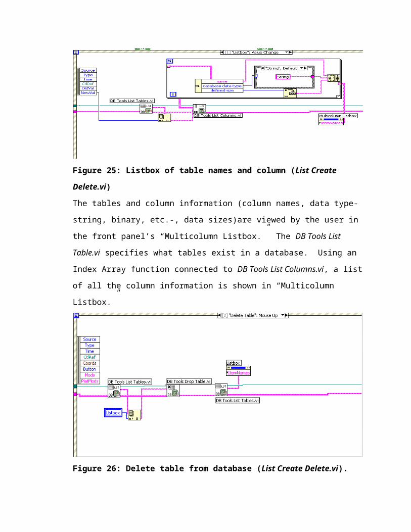
Figure 45: Slope and intercept information created in database using Calibration
Information in Database.vi.
Chapter 5: Discussion
The results demonstrate the utility of LabVIEW to allow access to a database for
robotic control.
The user is able to create, delete, or view the existing tables in a database from the
front panel interface in LabVIEW. The List Create Delete.vi is a valuable tool to those
persons who are not familiar or comfortable with database(s). The user is led from one
subVI to another by simple instructions. When user opens the Communicating with
Database.vi, immediately a dialog box opens which connects LabVIEW and MS Access
through a file path provided by UDL.vi. There is also an error checking method to
remind users to always enter a file path.
Once the user enters a dialog box, the subVIs List Create Delete.vi and
Retrieve.vi are enabled for selection by user. If the subVI List Create Delete.vi is chosen,
the user would be able to view all existing tables in the database, delete a particular table,
or create a new table (using Create Table & Column.vi ) to be seen in the Listbox once it
is uploaded into the database. The new table and any deleted table in List Create
Delete.vi are always refreshed to reflect the changes in the database as long as the VI is
executing. While the other VI, Retrieve.vi is an important tool for viewing all data that is
contained within a particular table. From the front panel in LabVIEW, the user can
quickly access and determine the information. For special queries, the user has the option
to query using SQL.
These subVIs are now useful to store dynamically changing information from the
robot into the database. Using labVIEW database interfacing for robotic control, the user
can now populate the setting of each axis while continuously store and update calibration
data from the robot. Another important issue these subVIs were able to address was
storing robot positioning information. This was accomplished through Calibration
Information in Database.vi.
Chapter 6: Conclusion
Overall, the Communication with Database.vi is a good tool for storage and
retrieving of information. The user has the ability to manipulate the database without
necessarily understanding the details of the implementation. The main goal of this
project to create an interface between LabVIEW and the database has been achieved.
InsertCalibration.vi and SlopeIntercept.vi, along with Communicating with Database.vi
have solved the issue of a place to continuously store and update the calibration data of
the robot, populate the setting of each axis and positioning inside the workplace, and also
store robot positioning information. This has been achieved by using a database, MS
Access, to allow easy search and access for any data needed for robotic control.
LabVIEW is a powerful tool for anyone because it allows novices to program
within its source code without a firm foundation in text-based programming language(s).
LabVIEW is a graphical programming language that allows the user to define instrument
functionality, not the instrument manufacturer.
The Database Connectivity Toolset is a valuable tool from LabVIEW. This
software is the means of communication between LabVIEW and any database. Unique
database operations defined by a user can be queried through SQL executions or simple
database transactions such as creating, listing, dropping tables and inserting data can be
manipulated by existing subVIs created by LabVIEW. “DB Create Table.vi,” “DB Drop
Table.vi,” “DB Insert Table.vi,” etc. are some examples of the VIs which only need the
user to enter controls and indicators for it to function.
Limitations and Future Endeavors
One noticeable limitation when using MS Access with LabVIEW is that as the
data information increases, the time for the refreshing a table if a new item has been
added or deleted is time-consuming. For scalability and a more robust and secure system,
Oracle should be utilized in a later project.
However, MS Access is reasonable for the functions it needs to perform in this
project.
References
[1] National Instruments. National Instruments™ LabVIEW™: Database
Connectivity Toolset User Manual. Austin, Texas, May 2001.
[2] Bishop, Robert. National Instruments Learning with LabVIEW 7 Express.
Upper Saddle River, NJ: Pearson Education, Inc., 2004.
[3] LabVIEW™ Database Connectivity Toolset v1.0
[4] Craig, J.J. Introduction to Robotics: Mechanics and Control. 3rd Edition. Upper
Saddle River, NJ: Pearson Prentice Hall, 2005.
[5] Hurst, Jeffrey W., and Mortimer, James W. Laboratory Robotics: A Guide to
Planning, Programming, and Applications. New York, N.Y.: VCH Publishers,
Inc. 1987.
[6] Niku, Saeed B. Introduction to Robotics: Analysis, Systems, Applications.
Upper Saddle River, NY: Prentice Hall, 2001.
Appendix
Curriculum Vitae
Netsanet Gebregziabher
B.Sc. (biology)
Phone: 317-243-3192 Email: [email protected]
SUMMARY
• Firm understanding on basic sciences through an undergraduate degree in
biology/minor chemistry
• Pursuing a master’s degree in Chemical Informatics (Specialization Laboratory
Informatics) at Indiana University, Indianapolis
SKILLS
Cheminformatics : Spotfire, ChemDraw
Molecular Modeling : Spartan, SYBYL
Databases : MS-Access
Web Technologies : FrontPage
Other : LabVIEW, Labware, Notebook (LabTrack), SDMS
(CyberLab), Waters eLab Notebook
EDUCATIONAL EXPERIENCE
•MS- Chemical Informatics, Indiana University Purdue University Indianapolis, Indiana
August 2004-Till date. Expected graduation May 2006
•Bachelor of Science (B.Sc.)-Biology (Minor in Chemistry), Xavier University of
Louisiana, New Orleans, LA.
WORK EXPERIENCE
Laboratory Informatics Research Associate: June 2005- May 2006- Laboratory
Graduate Program at the School of Informatics for Dr. Douglas Perry at Indiana
University Purdue University Indianapolis, Indiana.
• Worked with the Director of the Laboratory Informatics Graduate Program of the
School of Informatics (Dr. Douglas Perry) on creating a LabVIEW database
interface for robotic control
• Platform: LabVIEW
Laboratory Technician – June 2001-October 2005- Nice-Pak Products, Inc.,
Mooresville, IN
• Evaluated normality/abnormality in chemical liquid used in baby wipes
• Strengthened knowledge of HPLC method
• Tested, collected, and recorded data findings into a database
Research Assistant – October 1998-May 2001- College of Pharmacy at Xavier
University of LA, New Orleans, LA
• Studied mining bacterium
• Learned techniques that optimized life expectancy for bacterium
• Reviewed fundamental protein-ligand binding interactions
• Tested dopamine levels in mice
Summer Intern- June 1,1998-August 1, 1998- University of Missouri-Columbia,
Columbia, MO
• Experimented with Bradyrhizobium japonicum during symbiotic development
• Prepared plants for invasion of B. japonicum through assay process
RELEVANT WORKSHOPS
• NCBI workshop on MapViewer – November 2005
DETAILS OF COURSEWORK TAKEN
MS in Chemical Informatics
1) Lab Info Management Systems
2) Introduction to Informatics
3) Chemical Information Technology
4) Molecular Modeling
5) Informatics Management
6) Informatics Research & Design
7) Scientific Data Management Systems
Bachelor of Science
(Not a complete list)
1) Biochemistry
2) Organic Chemistry
3) Mathematics
4) Physics
5) Anatomy & Physiology
6) Genetics