Embed Size (px)
Citation preview

U -A098 300 AERONAUTICAL RESEARCH LABS MELBOURNE (AUSTRALIA) F/6 20/11REVIEW OF AUSTRALIAN INVESTIGATIONS ON AERONAUTICAL FATIGUE O--ETC(U)
U(JCASSIF ED AL/STRUC-TP,32 3L; ''IEEE/I//I//EEllhEEE/hh/hEEIEllEElllElllEEIEIDEEE-EEEEEEI

1111112.
1 .8
MIC I I N I B -6 I

ARL-STRUC-TCH-MEZO-327 AR-002-262
DEPARTMENT OF DEFENCE
DEFENCE SCIENCE AND TECHNOLOGY ORGANISATIONom ~AERONAUTICAL RESEARCH LABORATORIES
MELBOURNE, VICTORIA eE-LEC:TE" kPR 3 0 198! '
Structures Technical Memorandum 327
A REVIEW OF AUSTRALIAN INVESTIGATIONS ONAERONAUTICAL FATIGUE DURING THE PERIOD
APRIL 1979 TO MARCH 1981
Compiled by
G.S. JOST
kApproved for Public Release.0-1LiD THE UNITED STA.T&S NATI'jN:ALTECHNICAL INFORMATION SERVICE
/rnmi AUtTHCRI.tEO To
R-PR(..UCE AND SELL THIS REPORT
COMMONWEALTH OF AUSTRALIA 1981
COPY No1 MARcHi, 1981
>681 4 30 010

AR-002-262
DEPARTMENT OF DEFENCE
DEFENCE SCIENCE AND TECHNOLOGY ORGANISATION
AERONAUTICAL RESEARCH LABORATORIES
C1 Structures Technicai Memokandum 327
/ A REVIEW
, A RVIEW OF AUSTRALIAN JNVESTIGATIONS ON. AERONAUTICAL FATIGUE PURING THE PERIOD
APRIL 1979 TO MARCH 1981,
Compiled by
SUMMARY
This document was prepared for presentation to the 17th Conference
of the International Committee on Aeronautical Fatigue scheduled to be heldat Noordwijkerhout, the Netherlands on May 18 and 19, 1981. It is beingdistributed within Australia as an ARL Technical Memorandum.
A summary is presented of the aircraft fatigue research andassociated activities which form part of the programs of the AeronauticalResearch Laboratories, Commonwealth Aircraft Corporation Pty. Ltd.,Department of Transport (Airworthiness Branch), Royal Australian Air Forceand the Government Aircraft Factories. The major topics discussed includethe fatigue of both civil and military aircraft structures, fatigue damagerepair and refurbishment and fatigue life monitoring and assessment.
POSTAL ADDRESS: Chief Superintendent, Aeronautical Research Laboratories,P.O. Box 4331, MELBOURNE, Victoria 3001, AUSTRALIA.

DOCLIENT CONTROL DATA SHEET
Security classification of this page: UNCLASSIFIED1. DOCUMENT NUMBERS 2. SECURITY CLASSIFICATIONa. AR Number: a. Complete document:
AR-002- 262 UNCLASSIFIEDb. Document Series and Number: b. Title in isolation:
Structures Technical UNCLASSIFIEDMemorandum 327 c. Summary in isolation:
c. Report Number: UNCLASSIFIEDARL-STRUC-TECH-MEMO- 327
3. TITLE:
A REVIEW OF AUSTRALIAN INVESTIGATIONS ONAERONAUTICAL FATIGUE DURING THE PERIODAPRIL 1979 TO MARCH 1981.
4. PERSONAL AUTHOR: 5. DOCUMENT DATE:MARCH, 1981
JOST, G.S. 6. TYPE OF REPORT AND PERIODCOVERED:
7. CORPORATE AUTHOR(S): 8. REFERENCE NUMBERSAeronautical Research a. Task:Laboratories RD73
9. COST CODE: b. Sponsoring Agency:27003 SUPPLY 50/2
10. IMPRINT: 11. COMPUTER PROGRAM(S)Aeronautical Research (Title(s) and language(s)):Laboratories, Melbourne
12. RELEASE LIMITATIONS (of the document):
Approved for Public Release.
12.0. OVERS: ,.o. P.R. A B [ JcT JDT I E EL-13. ANNOUNCEMENT LIMITATIONS (of the information on this page):
No Limitation.
14. DESCRIPTORS: 15. COSATI CODES:Aircraft 0103Fatigue (Materials) 1113Structures 2012Reviews Australia 1407
050216. ABSTRACT:
This document was prepared for presentation to the 17th Conference of theInternational Committee on Aeronautical Fatigue scheduled to be held atNoordwijkerhout, the Netherlands, on May 18 and 19, 1981. A summary ispresented of Australian aircraft fatigue research and associated activities.The major topics discussed include the fatigue of both civil and militaryaircraft structures, fatigue damage repair and refurbishment and fatiguelife monitoring and assessment.

.*9/1
CONTENTS
PAGE NO.
9.1 INTRODUCTION 9/2
9.2 FATIGUE OF MILITARY AIRCRAFT STRUCTURES 9/2
9.2.1 Mirage 1110 9/2
9.2.2 GAF Nomad 9/4
9.2.3 NZAIL CT4-A Air Trainer 9/5
9.2.4 Canberra B. Mk. 20 9/6
9.3 FATIGUE IN CIVIL AIRCRAFT 9/7
9.3.1 General aviation fatigue 9/7
9.3.2 Airworthiness investigations 9/9
9.3.3 Helicopter fatigue 9/14
9.4 FATIGUE DAMAGED STRUCTURE: ANALYSIS, REPAIR AND
REFURBISHMENT 9/20
9.4.1 Mirage fatigue life extension program 9/20
9.4.2 Structural fracture mechanics and repair procedures 9/23
9.4.3 Repair of damaged composites 9/23
9.4.4 Application of BFRP crack patching to Mirage III aircraft 9/24
9.4.5 Testing of BFRP Patches 9/25
9.4.6 NDI research 9/26
9.4.7 Fatigue crack growth - allowance for R 9/26
9.4.8 Cracking in F-27 wings 9/27
9.4.9 Deductive fractography 9/27
9.5 FATIGUE LOADS, LIFE MONITORING AND ASSESSMENT 9/28
9.5.1 Aircraft measurements of gust encounters in Australia 9/28
9.5.2 Aircraft Fatigue Data Analysis System - AFDAS 9/29
9.5.3 Mirage risk analysis 9/30
9.5.4 Comparative fatigue testing 9/30
9.5.5 Springleg undercarriage design 9/31
9.6 BIBLIOGRAPHY ON FATIGUE Accession For 9/32
9.7 REFERENCES VTIS G0 A&I 9/33DTIC TAR
TABLE Unannouziced [
FIGURES Justificatior
DISTRIBUTION ByDistribution/
Availability Codes
jAvail and/orDist I special

9/2
9.1 INTRODUCTION
The general summary of Australian activity on aeronautical fatigue for the
two years to 1979 given in the previous ICAF ReviewI stated, in part, that
"in common with the situation in many other countries, economic circumstances
and requirements in Australia are forcing critical reappraisal of the many
aspects of aircraft fleet management with a view to maximising the effective
utilisation of existing aircraft". This trend, in which increasing fatigue
effort is being directed towards the solution of the more urgent shorter term
tasks, has certainly been maintained during the past two years. Thus, the
contributions to the Review reflect, in general, the more applied aspects of
developments in the fields of flight loads monitoring, fatigue evaluation
under simulated service conditions, non-destructive inspection and the repair
and refurbishment of fatigue-damaged structure.
This Review has been made possible by the co-operation of the author's
colleagues at the Aeronautical Research Laboratories, the Department of
Transport (Airworthiness Branch), the Royal Australian Air Force and in the
Australian aircraft industry, and their contributions to the Review are
gratefully acknowledged. Unless otherwise stated, the topics discussed
refer to work carried out at the Aeronautical Research Laboratories; other
information has been provided officially by the sources indicated. The names
of the various contributing organisations have been abbreviated as follows:
ARL Aeronautical Research Laboratories, Melbourne
BAe British Aerospace (Australia), Adelaide
CAC Commonwealth Aircraft Corporation Pty. Ltd., Melbourne
DOT Department of Transport (Airworthiness Branch), Melbourne
GAF Government Aircraft Factories, Melbourne
RAAF Royal Australian Air Force, Canberra.
9.2 FATIGUE OF MILITARY AIRCRAFT STRUCTURES
9.2.1 Mirage 1110 (ARL, RAAF)
The 1979 Australian ICAF Review I referred to details of a fatigue test
carried out at ARL on a single Mirage wing under a flight-by-flight loading
sequence representative of RAAF operational service. Since that test,
fatigue testing of a complete airframe has been underway at the Swiss Federal
Aircraft Factory (F+W), Emmen. Fatigue failures in the wings of the Swiss
test aircraft occurred at lives very much less than that of the Australian
test: initial attempts to equate the two test results using cumulative

9/3
damage theory and selected S-N data were unsuccessful2.
As part of a determined effort to resolve the reasons for the differences
in fatigue lives, a second series of static ground loadings was carried out
on a RAAF Mirage in order to refine the estimates of stress in the vicinities
of the failure locations of the two tests. In the ARL test, final failure
had occurred through a blind anchor nut hole in the lower spar surface,
while the F+W point of failure was through the No. 12 front flange bolt hole,
Fig. 9.1. Although results from the strain survey failed to resolve the
reasons for the difference in test lives , subsequent information obtained
during the calibration loadings prior to the second F+W fatigue test led to
a refinement in the cumulative damage calculation that resulted in agreement
being achieved between the two test results4 .
The co-operative program originally set up between Australia, Switzerland
and France to resolve the discrepancies outlined above has since been
examining the fatigue life of the Mirage III airframe and investigating
methods for improving it so that an increased life-of-type might be achieved.
This development came about as described below.
Following failure of the first wing on the Swiss test in 1979, a second
pair were installed, comprising a Swiss left hand wing and an Australian right
hand wing. The Australian wing was made available as a contribution to the
testing program so that the fatigue characteristics of the next most fatigue
critical region(s) in the airframe - thought to be the main wing-load-
carrying fuselage frame - might be discovered. Incidentally, it would also
provide an opportunity to monitor the performance of the boron fibre reinforced
plastic skin repair in the wing fuel drain hole region (reported in the1
1979 Review and in Section 9.4 of this Review) under accelerated simulated
service loading.
In September 1979 the discovery of significant cracking in bolt holes in
the spars of both wings and indications of cracks at identical locations in
a large number of wings of the RAAF fleet aircraft caused immediate concern
regarding the safety of the fleet and its ability to meet required life-of-
type. These events introduced an urgent need to develop methods for both
restoring and extending the fatigue lives of cracked wings; these are
reported in some detail in Section 9.4.1: this work is also the main subject5matter of a paper to be presented to the forthcoming 11th ICAF Symp0osium.

9/4
The refurbishments developed have been incorporated in the RAAF test wing
at F+W for final full scale evaluation concurrently with their general
application to RAAF Service aircraft.
9.2.2 GAF Nomad (GAF, ARL)
Nomad is an Australian designed and manufactured twin turbo-prop STOL
general utility aircraft, of which about 130 have been built. These aircraft
are being employed in military, civil, geophysical, medical and surveillance
roles.
6HA structural fatigue test on a Nomad airframe began in August 19766
The initially aimed-for fatigue life of 45,000 simulated flying hours was
attained in May 1978, and the test article reached 112581 flights during
October 1980 when there was an unexpected failure of the front spar of the
port stub wing just inboard of the fuselage wall at an undetected fatigue
crack. An in-situ inspection indicated that about 70% of the spar cap had
failed by fatigue with a static fracture of the shear web as shown in
Fig. 9.2. A 2g load was being applied when the failure occurred. The previous
ReviewI noted that at 72,000 flights some 41 cracks had been detected:
this number has now reached 103. Of these 8 have occurred in relatively
thick machined parts of the starboard stub wing front spar and end rib with
the remaining 95 in sheet metal components of the test article.
The Nomad fatigue test loading spectrum is based on a mean cruise weight
of 4182 kg (9200 lbs) and a one hour flight profile. Hence the test assumes
one landing per flight hour and 80% of the total landings used are based on
operation from prepared strips. A view of the test article in the loading
rig is shown in Fig. 9.3.
During the course of the test over 90 relatively minor cracks have been
identified and it is considered that several of these are non-representative
and attributed to the rig loading. Many cracks are monitored to obtain
crack growth data and are then repaired at a stage which, if found during
service, could be repaired by the operator. Of the significant fatigue
cracks found so far the following are of interest:
(1) Stub wing outboard rib cracks detected at 81700 test flights. A
repair was attempted but this did not stop the cracks from propaga-
ting and the rib was replaced at 104000 test flights.

9/5
(2) Port upper strut fitting failed unexpectedly at 79786 flights, at a
load of 2.5g. The fatigue crack had initiated by fretting between
packing strips and the machined fitting, Figs. 9.4 and 9.5.
(3) Removal of the stub wing outboard rib at 104000 flights enabled a
closer inspection to be made of the internal structure which resulted
in the detection of cracks in:
(a) the flanges on both port and starboard sides for attachment of
inter spar ribs (first rib inboard of tip, 119 cm from centreline)
to the front spar, which were in excess of 20 mm but have
progressed slowly, and
(b) the top flange of starboard front spar just outboard of station
119 approximately 10 mm long which progressed completely through
the flange at 107200 flights.
No failures or detectable cracks have yet occurred at any of the theoretical-
ly predicted critical areas. Testing is to continue after replacement of
the stub wing spar.
9.2.3 NZAIL CT4-A Air Trainer (ARL, RAAF)
The CT4-A Air Trainer is a two place, piston engined, fully aerobatic
trainer aircraft of 1070 kg all-up-weight produced in New Zealand for the
Royal Australian Air Force.
Progress towards the full scale fatigue test has been slower than desired;
however all flight tests have now been completed and the test rig has been
designed and manufactured. The flight tests had the following aims:
(a) to determine the loading distribution over the wings, fuselage,
fin and the tail plane during normal training flight,
(b) to check the characteristics of empennage vibrations observed
to exist under some circumstances.
Aircraft A19-031 was instrumented with 40 strain gauges and 28 other
transducers to monitor linear and angular accelerations, control surface
positions and engine parameters. All data were recorded onto a tape recorder

9/6
located beside the pilot. The format was digital,multiplexing at 3600 data/
second. Most of the 43 flights were simulated training missions, the remainder
being devoted to investigating parts of the flight envelope which were of
special concern.
As an aid to on-the-spot verification of the data, and the diagnosis of
faults, the ARL Quick Look Facility (a small minicomputer with magnetic tape
and graphics facilities) was used. This facility permitted checking of the
data immediately after each flight, a turn-around time of approximately
2 hours being achieved.
The flight tests were preceded and followed by static calibration of the
various strain gauges and transducers. A view of the aircraft in the ground
loading rig is shown in Fig. 9.6. Fatigue test loadings will include wing,
empennage and undercarriage loads as deduced from the flight trials data.
A finite element model of the aircraft wing structure is being used to help
in interpretation and extension of the experimental data, especially in the
wing root region. Figure 9.7 shows the mesh being used, for unloaded,
torsion and bending loading cases.
9.2.4. Canberra B. Mk. 20 (ARL, RAAF)
Canberra aircraft of the RAAF have been operating during their service life
on an individual safe life basis using fatigue meter data in conjunction with
a damage assessment formula for the fatigue critical region, the lower lug
of the DTD 683 centre section forging, Fig. 9.8. Although the damage formula7being used was originally developed at ARL , it has since been modified as
required by the RAAF to reflect current flight configurations.
In view of uncertainties now known to exist in the assessment of fatigue
damage, ARL is investigating the feasibility of operating these aircraft on
a safety by inspection basis. Such a consideration requires the evaluation
of the residual strength and crack growth characteristics of the fatigue
critical region and, of course, accessibility for inspection. This latter
requires that both wings and lug bushes be removed. The lugs of all aircraft
have recently been inspected and have been found to be free of detectable
cracks.

9/7
The estimation of residual strength has been approached both analytically
and by means of finite element analysis, Fig. 9.9. Analytically, the lug is
approximated usingNewman's 1976 approach8 for through and part-through
cracks in a partially pin loaded hole-in-bar. It turns out that the analyti-
cal solutions provide stress intensity estimates just above those of the
corresponding finite element analysis; their direct use therefore provides
a little inbuilt conservatism, as well as complete manipulative flexibility,
in crack growth and residual strength assessments. The critical crack depth
is typically rather shallow, but above the threshold of detectability.
Crack growth predictions have been made using Forman's equation9 . Insofar
as no retardation is allowed for in that formulation, crack growth predictions
are likely to be conservative particularly in the low crack growth rate
region. Even so, calculated inspection intervals are reasonable, so that
the feasibility of the proposal has in fact been established on the basis
of calculations to date 0 . Before implementation in service, however, fatigue
testing of lug specimens under a representative loading sequence is to be
carried out to check all predictions concerning the fatigue and residual
strength behaviours of the cracked lug.
9.3 FATIGUE IN CIVIL AIRCRAFT
9.3.1 General aviation fatigue (DOT)
For some years the Australian Department of Transport has had a policy of
establishing and promulgating fatigue retirement lives, as necessary, for1
general aviation aircraft. The 1979 ICAF review provided details of this
policy.
With aircraft engaged in commuter operations it has been the practice to
obtain selected time expired wing spars for detailed metallurgical
examination. Not unexpectedly, no fatigue cracking has yet been discovered.
However, during the examination of a time expired wing main spar from a
Cessna Model 402 it was discovered that a section of the aluminium alloy
had been seriously affected by heat. During the subsequent follow up work
related to this occurrence a further two cases of heat affected spars and
another two cases of seriously heat affected wing structure were discovered
on Cessna twin engined aircraft in service. The aircraft involved were two
Model 402, one Model 421 and one Model 320.

9/8
The heating of these particular spars appears to have resulted from engine
exhaust leaks allowing exhaust flame impingement on to the firewall, leading
to a high temperature build up during flight (through convection and seepage)
in the enclosed area behind the firewall. Inspection of the spar from one
aircraft revealed that the starboard spar cap had been considerably affected
by heat. The affected area extended several inches along the spar in the
area of the exhaust pipe. The front spar web was also found to be damaged by
heat and was replaced during the spar change operation.
Discolouration of the paint on the lower surface of the spar gave visual
evidence of the extent of the heat affected area. Although there were two
areas of discolouration, electrical conductivity tests showed only one area
to be significantly affected by heat. Paint discolouration, particularly
7 darkening of zinc chromate primers, is usually a good indicator that the
strength of aluminium alloy parts has been significantly reduced but it is
necessary to distinguish between darkening of the paint coating and smoke
staining of the paint surface which may take place without significant
temperature rise.
The spar was sectioned and hardness tests were carried out. Results of
these tests indicated that spar strength had been reduced to approximately
half its original yield strength value. Two other spars known to have been
heat affected due to engine exhaust leaks were also subjected to electrical
conductivity and hardness tests. From the results obtained it was clear that
the strength of these spars had also been reduced to approximately half the
original yield strength value.
It was estimated from laboratory tests that to produce this degree of over-
ageing a spar would need to be subjected to local temperatures in the range
220 to 290 C for between sixty and thirty minutes respectively. It has
been further estimated that, during flight with local spar heating to
temperatures of this order, the spar strength would have been reduced to
approximately 25% of its design ultimate. Thus it was extremely fortunate
that no severe inflight gust loads were encountered while the spar was at
these high temperatures. In the case of the time expired spar, local
buckling had occurred in the heat affected area and the wing had a permanent
set (wing tip up).

9/9
Apart from the marked loss of static strength a significant reduction in
fatigue life could be anticipated in this highly zLLessed area. The working
stress levels in the affected area represent a much higher proportion of the
locally reduced ultimate strength and thus accumulate damage at a much higher
rate.
9.3.2 Airwothiness ir.vestiqations (DOT)
Embraer EMB-110 Bandeirante
Some 12 Bandeirante aircraft are engaged in commuter operations in Australia.
At the time of Australian certification an interim life was established for
the wing of this aircraft. Subsequently a full scale fatigue test has been
carried out, Fig. 9.10, resulting in a wing main spar lower cap failure
occurring at 188000 simulated flights.
In addition to carrying out their own investigation of the wing test failure
in Brazil, the manufacturer offered one side of each of the fracture faces to
the Airwothiness Branch of the Department of Transport Australia. In view of
the complex nature of the test loading and the airworthiness implication of
establishing reliable crack propagation rates, it was decided that an
independent metallurgical examination of the parts was desirable. Accordingly
the offer from Embraer was accepted.
The sequence adopted for the fatigue test is illustrated in Figure 9.11.
The spar failed in the fatigue test rig at the rib 6 attachment bolt hole
during the last gust cycle of the last flight in the 188th application of the
1,000 flight program of the fatigue test i.e. the peak load of the 188th block.
Flight F4545 has the highest peak load in the entire program, and this occurred
after block numbers 185, 181, 176, 172, 167, 163, 158, 154, 149, 145, 140, 136,
131 and so on.
The lower front spar,manufactured from 2024T351 material, consists of a
forward cap and a rear cap with the spar web bolted between the two caps. The
rear cap had been cut into three sections, one cut being through the bolt hole
and the other cut being through the end of one of the fractures. The four
fracture surfaces of the front spar lower cap will be referred as A, B, C and
D for convenience, Fig. 9.12.
9/10
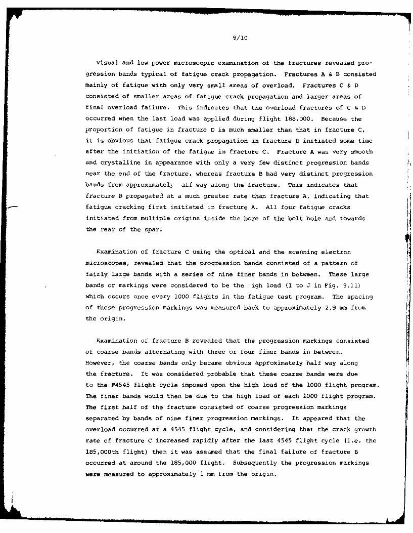
Visual and low power microscopic examination of the fractures revealed pro-
gression bands typical of fatigue crack propagation. Fractures A & B consisted
mainly of fatigue with only very small areas of overload. Fractures C & D
consisted of smaller areas of fatigue crack propagation and larger areas of
final overload failure. This indicates that the overload fractures of C & D
occurred when the last load was applied during flight 188,000. Because the
proportion of fatigue in fracture D is much smaller than that in fracture C,
it is obvious that fatigue crack propagation in fracture D initiated some time
after the initiation of the fatigue in fracture C. Fracture A was very smooth
and crystalline in appearance with only a very few distinct progression bands
near the end of the fracture, whereas fracture B had very distinct progression
bands from approximatel alf way along the fracture. This indicates that
fracture B propagated at a much greater rate than fracture A, indicating that
fatigue cracking first initiated in fracture A. All four fatigue cracks
initiated from multiple origins inside the bore of the bolt hole and towards
the rear of the spar.
Examination of fracture C using the optical and the scanning electron
microscopes, revealed that the progression bands consisted of a pattern of
fairly large bands with a series of nine finer bands in between. These large
bands or markings were considered to be the igh load (I to J in Fig. 9.11)
which occurs once every 1000 flights in the fatigue test program. The spacing
of these progression markings was measured back to approximately 2.9 mm from
the origin.
Examination of fracture B revealed that the progression markings consisted
of coarse bands alternating with three or four finer bands in between.
However, the coarse bands only became obvious approximately half way along
the fracture. It was considered probable that these coarse bands were due
to the F4545 flight cycle imposed upon the high load of the 1000 flight program.
The finer bands would then be due to the high load of each 1000 flight program.
The first half of the fracture consisted of coarse progression markings
separated by bands of nine finer progression markings. It appeared that the
overload occurred at a 4545 flight cycle, and considering that the crack growth
rate of fracture C increased rapidly after the last 4545 flight cycle (i.e. the
185,000th flight) then it was assumed that the final failure of fracture B
occurred at around the 185,000 flight. Subsequently the progression markings
were measured to approximately 1 mm from the origin.

9/11
Examination of fracture A revealed similar characteristics to the first half
of fracture B, having coarser progression markings with nine finer progression
markings in between. These coarse progression markings became more pronounced
near the end of the fracture and every four or five bands were more prominent
indicating a 4545 flight cycle plus a peak load in the 1,000 flight program. In
fracture B, the crack growth rate alters at approximately 138,000 flights
(See Fig. 9.13)and it was considered that this resulted from the final failure
of fracture A. This is in agreement with a pronounced band in fracture A being
a F4545 flight cycle at 136,000 flights and another F4545 pronounced band at
131,000 flights. Hence the progression markings were measured to within
approximately 1 mm from the origin. Fracture A was examined using the scanning
electron microscope and there was no evidence of significant corrosion or
fretting at the fatigue origins. A section was taken through one of the origins
for metallographic examination. There was no evidence of corrosion or other
significant metallurgical defects in the vicinity of the crack origin.
By assuming that the coarse progression markings were associated with the
1000 flight block, it was possible to plot crack growth rates; an example is
shown at Fig. 9.13. By extrapolating these curves, it is considered that the
timing and sequence of events were as follows:
Event Approx. Test Flights
Fatigue crack A initiated 70,000
Fatigue crack in A propagated 1.5 mm 105,000
Fatigue crack B initiated
Final failure of A
Fat.gue crack growth rate of 138,000
B suddenly increases
Fatigue crack initiated in C
Fatigue crack D initiated After 138,000
Final failure of B
Fatigue crack growth rate 185,000
suddenly increases in C
Final failure of C & D 188,000

9/12
The above information is of prime importance in considering future air-
worthiness action on this aircraft type.
On a purely theoretical safe life basis the unfactored life should be
taken as the last point where design ultimate strength (1.5 x critical limit
load) was still attainable on a residual strength basis. Apart from any
loading spectra adjustments this would mean that the full 188000 flight life
could not be accepted as the mean life.
The other extreme could be to consider a fail-safe approach. However, in
this case it would be necessary to ensure that all the spar cap was inspectable
and that all other possible wing failure locations were identified.
It is possible that a better approach would be a mixture of the two criteria;
safety by inspection combined with a life limitation. With such an approach,
a relatively low sensitivity inspection method capable of detecting major cracks,
say of 12 mm or greater in length, together with a suitable inspection interval,
could be combined with a somewhat greater retirement life i.e. a lower scatter
factor than would be accepted on a purely safe life basis. Such an approach
is common on helicopters and would enable some advantage to be taken of the
very slow crack propagation rate demonstrated for the Bandeirante spar. The
magnitude of any reduced scatter factor which could be accepted in this case
woula depend upon the development of suitable inspection techniques and
further fatigue testing of the repaired wing to ensure that other possible
wing failure locations are adequately covered.
Lockheed L.188 Electra
The Electra is a large propeller turbine transport aircraft designed to
the structural fail-safe standards of CAR 4b.270 and certificated in 1958.
The wing lower surface is composed of nine integrally stiffened taper-
machined extruded panels of 7075-T6 material approximately 14 inches wide.
All panels are continuous for their entire length except for a full chord
splice joint at BL 65 near the wing root. The front and rear spars of the
structural box utilise machined 7075-T6 extruded spar caps with machined
plate webs. The spars are also joined at each side of the fuselage at BL 65.
The main joint at BL 65 is shown in Fig. 9.14. The plank ends butt
together with a splice plate on the outside and a rib cap 'T' section member
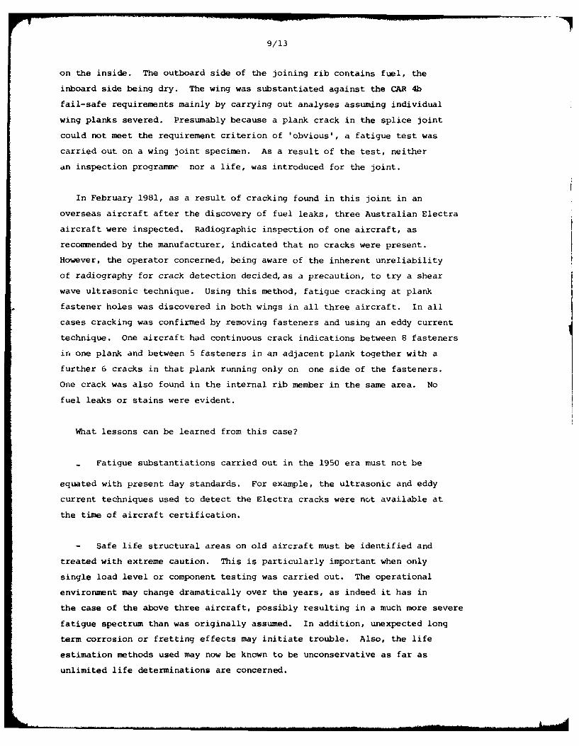
9/13
on the inside. The outboard side of the joining rib contains fuel, the
inboard side being dry. The wing was substantiated against the CAR 4b
fail-safe requirements mainly by carrying out analyses assuming individual
wing planks severed. Presumably because a plank crack in the splice joint
could not meet the requirement criterion of 'obvious', a fatigue test was
carried out on a wing joint specimen. As a result of the test, neither
an inspection programmr nor a life, was introduced for the joint.
In February 1981, as a result of cracking found in this joint in an
overseas aircraft after the discovery of fuel leaks, three Australian Electra
aircraft were inspected. Radiographic inspection of one aircraft, as
recommended by the manufacturer, indicated that no cracks were present.
However, the operator concerned, being aware of the inherent unreliability
of radiography for crack detection decided, as a precaution, to try a shear
wave ultrasonic technique. Using this method, fatigue cracking at plank
fastener holes was discovered in both wings in all three aircraft. In all
cases cracking was confirmed by removing fasteners and using an eddy current
technique. One aircraft had continuous crack indications between 8 fasteners
in one plank and between 5 fasteners in an adjacent plank together with a
further 6 cracks in that plank running only on one side of the fasteners.
One crack was also found in the internal rib member in the same area. No
fuel leaks or stains were evident.
What lessons can be learned from this case?
- Fatigue substantiations carried out in the 1950 era must not be
equated with present day standards. For example, the ultrasonic and eddy
current techniques used to detect the Electra cracks were not available at
the time of aircraft certification.
- Safe life structural areas on old aircraft must be identified and
treated with extreme caution. This is particularly important when only
single load level or component testing was carried out. The operational
environment may change dramatically over the years, as indeed it has in
the case of the above three aircraft, possibly resulting in a much more severe
fatigue spectrum than was originally assumed. In addition, unexpected long
term corrosion or fretting effects may initiate trouble. Also, the life
estimation methods used may now be known to be unconservative as far as
unlimited life determinations are concerned.

9/14
Finally, it is submitted that this particular Lockheed Electra problem
provides excellent support for the current structural audit approach to
the airworthiness of older aircraft and for the introduction of the new
FAR 25.571 amendment 45 damage tolerance standards for new designs.
9.3.3 Helicopter fatigue (DOT)
During the period under review, considerable effort has been necessary
with regard to in-service fatigue problems with helicopters. Approximately
550 Australian Airworthiness Directives are promulgated each year in
connection with the whole spectrum of problems concerning the 6500 or so
powered aircraft registered in the country. Although only 215 or 3.3% of
these aircraft are helicopters it is worthy of note that around 10 percent
of all Australian Directives relate to helicopter fatigue problems.
A few typical cases have been selected to illustrate the range of
problems involved. Although these generally did not involve any great
research effort or change the fatigue 'state-of-the-art', they did involve
considerable engineering investigation, sometimes loss of life and always
an economic penalty.
Westland Wessex 60 main rotor blade
The Australian Department of Transport recently became aware that a
locally operated Westland Wessex 60 helicopter had suffered a main rotor
blade pressure loss (BIM) indication, which had been confirmed as resulting
from a spar defect.
The blade had been removed from service on an earlier occasion because
of a BIM indication, and had been forwarded to the manufacturer for overhaul.
The cause had been identified as leaking seals, and following repair the
blade was whirl rig tested and cleared for service. On this new occurrence
4.75 flying hours later, halogen leak tests confirmed a spar defect at
mid-span. The blade total time was 1373 hours.
The portion of the blade containing the defect was obtained by the
Department for investigation. Eddy current inspection confirmed a chordwise
crack in the lower surface near the rear corner of the extruded D section
spar, where the trailing edge skin is bonded to the spar. The crack was
broken open and found to be a fatigue crack 25 mm long, which had initiated
and grown forward and aft fro, a small dent or pit-like depression 0.05 un

9/15
deep. Two further small cracks 0.2 mm long were also present, and had no
obvious initiators. Fig. 9.15 illustrates the fatigue fracture.
Optical and electron microscope examination and measurements of the
fatigue striation markings enabled calculation of the crack propagation
rates. At an assumed rotor speed of 230 RPM, the crack front had advanced
from close to the origin, to the length as found, in 11.7 hours. Staining
marks on the crack surface suggested that the crack had been present when
the blade was overhauled 4.75 hours previously, but had not propagated
through the blade section and hence ckild not reasonably have been found by
normal overhaul procedures. Other work on Wessex blades, and experience
with similarly constructed blades on other helicopters, suggests that the
remaining time to complete blade failure in this case could have been as
little as 2.9 hours.
It is of interest to note that, although the crack broke through the
section perhaps 3-4 hours before discovery, escape of gas could not readily
occur because of the overlying bonded trailing edge skin, and the crack
had to grow to the edge of the skin before the BIM system could function
effectively.
As a result of this experience, Australian aircraft with blades over
6UO flying hours must have BIM checks carried out at intervals of 1 hours,
which incidentally precludes operation of affected aircraft on long
overwater flights. The occurrence further emphasizes the necessity for
rigid observance of, and adherence to, the laid down inspection schedules
and procedures.
Sikorsky S61 spindle
Some years ago there were fatigue problems with S61 main rotor spindles.
These were concerned with the shank portion and were overcome by introducing
the current 3000 hour retirement life and by other measures.
In June 1978 Helikopter Services of Norway lost an aircraft in the North
Sea following the fatigue failure of a spindle lug at 1950 hours. This
resulted in an extensive program of further fatigue testing and flight
loads evaluation together with world-wide inspections.
To date the only spindles found cracked, apart from one U.S. Coast-Guard
failure, are from Helikopter Services aircraft. Generally, flight stress

9/16
levels have been below the endurance limit for the SAE 4340 steel used
although some higher loads were measured during Helikopter Services spot landing
training. Their particular operations involve extreme range whereby in the
case of an engine failure single engine spot landings on oil platforms are
unavoidable. Blade flap stop pounding resulting from training to meet this
eventuality introduces higher than normal loads on the spindle. However,
these may not be sufficiently high to fully explain the accident failure.
In order to keep aircraft in service, a safety by inspection approach
was adopted using an ultrasonic inspection technique. Additional fatigue
testing has enabled the inspection interval to be gradually extended
from 25 to 180 hours. Crack propagation appears to be relatively intensitive
to flight cycles which has therefore enabled an interval to be set in flight
hours. The time to crack initiation however is affected by flight cycles
and hence the inspection interval has been set at 200 hours or 200 flights
whichever occurs first.
A new spindle is in the process of development. This utilises the same
basic forging hub with modified machined dimensions.
Hiller control rotor cuff
There have been a number of accidents involving fatigue failure of the
control rotor on UH-12E helicopters.
In one local accident the pilot lost control of the aircraft and it crashed
following the fatigue failure of one control rotor spar. The tubular steel
spar failed at the outer of two bolts which attach it to the cuff at a total
time in service of only 321 hours.
All four attachment bolts (two from each spar), which had been installed
at the most recent 100 hourly inspection 39 hours prior to the accident,
showed significant fretting where they had been in contact with the steel
tube. The nut end of the bolt at which the failure had occurred, showed a
clear imprint of the crack in the fretting pattern. This provided evidence
that the spar crack had been present for some period of time prior to the
accident.
It was also established that the cyclic control upper scissors link from
the opposite control blade had been replaced at or shortly before the last

9/17
100 hourly inspection because of extreme wear and distress in the spherical
bearing, with sufficient free play to allow 30 of movement in the incidence
angle of the control rotor a.rofoil. It has been suggested that this free
play could have thrown additioial cyclic loads into the opposite control
blade and thus contributed to the spar fatigue failure.
Examination of the component and correspondence with the manufacturer has
indicated that the existing 100 hourly dye penetrant inspection is sufficient
to detect this type of problem. However, this accident highlights the
necessity for carrying out the inspection carefully and meticulously.
Bell 47 tail rotors
The Bell 47 metal tail rotor blade P/N 47-642-102 retirement life was
originally 2500 hours. In January 1968, following an assessment by the
Bell Company of some 53 blade service failures, the life was reduced to
600 hours and additional inspections introduced.
Four failure locations showed up in service, the most troublesome being
in the grip internal bearing relief radius which was the origin of 25
reported failures. All these failures were at over 600 hours blade time in
service with a mean of around 1500 hours.
In November 1979 the Department of Transport reduced the life of -102
blades on Model G and G2 helicopters to 300 hours. This followed two
accidents in Australia to cattle mustering G2 helicopters following tail
rotor blade failure at the relief radius, both below the 600 hour life. This
action was later extended to all Models.
It was possible for operators to avoid the 600 hour life on all Models
except the G & G2, by fitting -117 Bell 206 type tail rotor blade assemblies
which had a 2400 hour life. In December 1979 Bell issued Service Bulletins
which recommended a 300 hour life for all -102 blades and extended the 206
type tail rotor modification to all Bell 47 Models.
Earlier this year advice was received of six further accidents overseas
with 10 fatalities all resulting from -102 blade fatigue failures at less than
600 hours total time. Following this information and the issue by the FAA
of an Airworthiness Directive which followed the Bell recommendation, the
matter was again reviewed. Accordingly, an Australian Directive has now

9/18
been issued requiring replacement of all -102 blades by -117 blades prior to
July 1, 1981.
Bell main rotor blade tension/torsion retention straps
In April 1976 an accident occurred to a Bell 206B helicopter which involved
the failure of a main rotor retention strap. Fatigue was identified in a
number of the broken 0.15 mm dia. wires. Following this event the strap life
on the Model 206 was reduced from 2400 to 1200 hours. In December 1976 and
March 1977 further accidents occurred involving Bell 206B strap failures.
At this stage a 6 month strap life was introduced for aircraft operating in
a salt environment.
Until 1973 a proprietary brand name curing agent called MOCA was used in
the polyurethane coating of the rete, .ion straps. These gave no trouble in
many years of service. Unfortunate L. this agent was withdrawn from use on
health grounds and an alternati-e - CAYTUR 21, was substituted.
In August 1977 a Bell 205 rete5°4ion strap was analysed at the Materials
Research Laboratories in Melbourne. This work identified the coating as also
incorporating the CAYTUR 21 curing agent and commented on the porosity of
the cover and the presence of sodium chloride as a constituent. Accordingly
the Department of Transport reduced the life of straps in Australian Bell 205
and 212 aircraft from 2000 to 500 hours. In September, Bell recommended a
life reduction to 1000 hours.
At this stage the strap problem appeared to be over. New straps using
the original MOCA cure were becoming available for all aircraft. The new
lives were 1200 hours for straps on the Bell 206 and 2400 hours for straps
on the Bell 205 and 212, with no calendar restriction.
However, in April 1980 advice was received of an accident to a Bell 212
helicopter in which one of the new straps was found to be broken, Fig. 9.1b.
The metallurgical examination of 16000 fractured 0.15 mm dia. wire ends is
a formidable task and will take some time to complete. In the meantime the
life of the new type straps has been reduced to 1200 hours and a 24 months
calendar limit placed on all models.
An urgent program of examining retired straps is being conducted in all
attempt to find a solution to the problem.
9/19
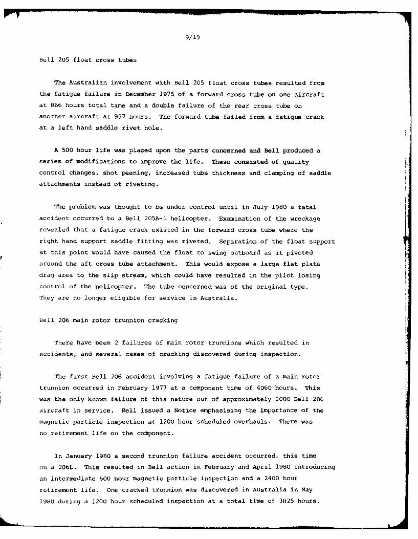
Bell 205 float cross tubes
The Australian involvement with Bell 205 float cross tubes resulted from
the fatigue failure in December 1975 of a forward cross tube on one aircraft
at 866 hours total time and a double failure of the rear cross tube on
another aircraft at 957 hours. The forward tube failed from a fatigue crack
at a left hand saddle rivet hole.
A 500 hour life was placed upon the parts concerned and Bell produced a
series of modifications to improve the life. These consisted of quality Vcontrol changes, shot peening, increased tube thickness and clamping of saddle
attachments instead of riveting.
The problem was thought to be under control until in July 1980 a fatal
accident occurred to a Bell 205A-1 helicopter. Examination of the wreckage
revealed that a fatigue crack existed in the forward cross tube where the
right hand support saddle fitting was riveted. Separation of the float support
at this point would have caused the float to swing outboard as it pivoted
around the aft cross tube attachment. This would expose a large flat plate
drag area to the slip stream, which could have resulted in the pilot losing
control of the helicopter. The tube concerned was of the original type.
They are no longer eligible for service in Australia.
Bell 206 main rotor trunnion cracking
There have been 2 failures of main rotor trunnions which resulted in
accidents, and several cases of cracking discovered during inspection.
The first Bell 206 accident involving a fatigue failure of a main rotor
trunnion occurred in February 1977 at a component time of 4060 hours. This
was the only known failure of this nature out of approximately 2000 Bell 206
aircraft in service. Bell issued a Notice emphasising the importance of the
magnetic particle inspection at 1200 hour scheduled overhauls. There was
no retirement life on the component.
In January 1980 a second trunnion failure accident occurred, this time
on a 206L. This resulted in Bell action in February and April 1980 introducing
an intermediate 600 hour magnetic particle inspection and a 2400 hour
retirement life. One cracked trunnion was discovered in Australia in May
1980 during a 1200 hour scheduled inspection at a total time of 3825 hours.
9/20
Fatigue cracks were discovered in the lower leading position in the under-
cut radius of both spindle inboard ends. No metallurgical flaws were
discovered which may have initiated the cracking.
A re-evaluation of the fatigue substantiation of the trunnion has failed
to fully explain the current problem. However, a new trunnion has now been
introduced with a larger fillet radius and a shot peened surface.
9.4 FATIGUE DAMAGED STRUCTURE: ANALYSIS, REPAIR AND REFURBISHMENT
9.4.1 Mirage fatigue life extension program (ARL, CAC, RAAF)
As discussed in Section 9.2.1, the discovery of extensive cracking from
certain bolt holes in the main spars of service aircraft has resulted in an
extensive and urgent laboratory program aimed at providing effective
refurbishment procedure(s).
A comprehensive series of fatigue tests on large specimens of a size and
geometry closely representing the critical section of the spar was undertaken
at ARL. At the commencement of the investigation the development of a
refurbishment scheme was based upon a "standard" test specimen, Fig. 9.17,
designed directly from the drawings of the spar. However, subsequent detailed
examination of spars from crashed aircraft and other wings indicated a
number of serious discrepancies between the actual spars and the drawings
at the critical section. The most significant of these were the use of
0.125 inch (3.175 mm) 2117 rivets instead of 2.5 mm A-U4G rivets to hold the
Single Leg Anchor Nut (SLAN), and that the SLAN rivet holes often tended to
converge towards the 8 mm bolt hole at the outer surface of the spar rather
than be parallel to it. These differences required that certain aspects of
the refurbishment be investigated in much greater detail than was originally
anticipated. Because of continuous up-dating of "in-service" information on
cracking and wing conditions, the task has broadened to include the determina-
tion of crack propagation rates and residual static strengths with cracks of
different sizes, and the effects on fatigue life and crack growth rates of
spectrum truncation.
In the original development of a method for extending the fatigue life of
the relevant parts of the wing spar it was considered essential to completely
remove any pre-existing fatigue cracks. It was apparent early in the
investigation that the SIAN section would be the most critical - a typical
fatigue specimen fracture surface is shown in Fig. 9.18. Thus the major effort
was directed towards improving the life at the 8 mm bolt hole and adjoining

9/21
rivet holes, and a basic requirement was to enlarge the diameters of these
holes for the purpose of either removing cracks, or to clean up for inspec-
tion and/or accurate sizing for a subsequent operation.
Of the various refurbishment options available, those covered by this
investigation were:
(a) oversize reamed bolt holes, utilizing close-fit bolts;
(b) interference-fit (0.3%) low-alloy steel bushes of 1.5 mm
wall thickness, utilizing standard bolts;
(c) bolt holes cold-expanded (2.7% or 3.6%) by the Boeing
split-sleeve process;
(d) oversize reamed and/or cold-expanded (non-sleeve) rivet
holes;
(e) modified anchor-nut assemblies - used in conjunction with
(in particular) options (b), (c), and (d).
The fatigue specimens were manufactured from two batches of 46 and 48 mm
thick plates of A7.U4SG aluminium alloy, which is equivalent to 2214
aluminium alloy. All fatigue tests were carried out under a 100-flight
-2.5g to +7.5g loading sequence derived from the Swiss Mirage test spectrum,
details of which are given in Fig. 9.20. For every specimen the fatigue
loads were based on the gross area at the SLAN section (not including the
skin plate), the +lg and +7.5g gross area stresses being 24 MPa (3480 psi)
and 180 MPa (26100 psi) respectively. For the standard control specimens
with 2.5 mm diameter SIAN rivets the net area stresses are about 20% greater
than the gross area stresses. Over 100 specimens with various configurations
and treatments have been fatigue tested including 16 which were refurbished
after the development of significant fatigue cracks in holt holes at lives
corresponding to between 25% and 50% of their estimated total fatigue lives.
The results of this investigation will be presented in detail in a5paper prepared for the llth ICAF Symposium , and thus only the major conclusions
will be given in this Review. They are as follows:
A. Parallel SLAN rivet holes
(i) A progressive reduction in fatigue life results if the 8 mm SLAN
bolt hole is reamed to a larger diameter and fitted with oversize
close-fit bolts. For an 11 mm bolt the life is reduced to about
60% of that of the relevant control specimens.

9/22
(ii) Cold expanding of the 8 mm SLAN bolt hole to 8.6 mm diameter
provides a slight increase in life compared with the relevant
control specimens; but expanding to larger diameter reduces the
life to less than that of the control specimens, although the
oversize expanded holes result in greater fatigue lives than
oversize reamed holes of the same diameter. The reduced lives of
the cold-expanded bolt hole specimens were associated with problems
introduced by the rivet holes in close proximity and decreased
hole/spar edge distances.
(iii) Sliding-fit steel bushes provide no advantages (from the fatigue-
viewpoint) compared with close-fit bolts of the same diameter.
(iv) Interference-fit bushed holes can provide a significant increase
in fatigue lives compared with holes of the same external diameter
fitted with oversize close-fit bolts and, furthermore, improved
lives compared with standard control specimens. The fatigue lives
of specimens with 11 mn outside diameter bushes were 75% greater than
those of the relevant 8 mm diameter bolt control specimens. A
typical failure is shown in Fig. 9.19: crack initiation at the bolt
hole is suppressed and the rivet holes become the critical feature
of the section.
(v) An increase in fatigue life occurs if interference-fit bushes are
fitted into cold-expanded bolt holes.
B. Inclined SLAN rivet holes
(i) Reduced pitches between bolt holes and rivet holes result in
reductions in fatigue life and introduce difficulties in applying
a refurbishment scheme based on the use of standard bolts and
1.5 mm wall thickness interference-fit steel bushes, because of
the greater incidence of fatigue cracking between the bolt and
the adjacent rivet hole.
(ii) Interference-fit steel bushes of suitable outside diameter and,
if necessary, with bores of less than 8 mm diameter can not only
provide significant increases in the fatigue lives of specimens
with uncracked bolt holes, but have the potential for improving
the lives of specimens containing residual fatigue cracks prior
to the fitment of the bushes.
In summary, this research has shown that adequate extensions in fatigue
life are possible by the fitment of interference-fit steel bushes into over-
size bolt holes after the removal of pre-existing fatigue cracks. With the

9/23
particular bolt/rivet detail configuration in the spar under investigation
the use of the Boeing split-sleeve hole cold-expanding process is not an
acceptable refurbishment alternative. The interference-fit Oush technique
has been incorporated in the RAAF test wing at F+W and is being used in
the refurbishment of Mirage 1110 aircraft in the RAAF fleet.
9.4.2 Structural fracture mechanics and repair procedures
Considerable attention is being given to stress analysis problems
associated with cracked structures. Broadly this involves a combination of
finite element and fracture mechanics concepts.
One problem area of substantial current interest is the possibility of
the repair of cracks in thick sections. A three-dimensional crack tip element
has been developed and this has been used to study the repair of semi-circular
and semi-elliptical surface cracks using a bonded overlay of high strength
composite materialI. This element has also been used to study the repair of
a through crack, again using a boron epoxy laminate, in a section 12.7 mm thick.
The results to date are very encouraging and the numerical predictions are
being tested by a series of simple laboratory tests.
Another problem area -f interest is the repair of cracks in thin sheets
(e.g. wing skins). A detailed design study has been completed 1 2 which now
simplifies patch design. In addition to this, a crack opening displacement13approach to crack patching has also been developed . A major potential
problem area in crack patching is the thermal mismatch problem which arises
due to the difference in the coefficients of expansion of the sheet and the
patch during curing of the adhesive. This has also been studied in some14
detail in connection with the boron fibre plastic patches which have now15-17
been installed on Australian Mirage aircraft . Patching is used there
to repair cracks of up to 110 mm in length and has been found to restore the
stress distribution in the spar with a cracked skin to the same level as that
with an uncracked skin.
9.4.3 Repair of damaged composites
A review of the numerical methods available for the analysis of composite
laminates has been undertaken 1 8 and the interconnectien with new elements,
developed for the analysis of the repair of composite laminates, has been
clearly shown. These elements have been used to analyse the effectiveness of
various scab patches used to repair cracks and holes in composite laminates.

9/24
An advanced iso-parametric element is also being Jeveloped specifically
for the analysis of disbonds and internal flaws in composite laminates. It
is anticipated that this element will be incorporated into the finite element
program PAFEC in use at ARL.
9.4.4 Application of BFRP crack patching to Mirage III aircraft
ARL has pioneered the use of adhesively bonded boron-fibre reinforced
plastic (BFRP) patches to repair cracks in aircraft components. This
procedure has been used successfully in several applications on RAAF aircraft,
including the field repair of stress-corrosion cracks in the wings of
Hercules aircraft and fatigue cracks in the landing wheels of Macchi
aircraft 19'20. Repairs were made by adhesively bonding the BFRP patch to the
component with the fibres spanning the crack; the aim was to restrict opening
of the crack under load, thereby reducing stress-intensity and thus preventing
further crack propagation. Adhesive bonding provides efficient load transfer
into the patch from the cracked components and eliminates the need for the
additional fastener holes (which introduce dangers such as fretting)
associated with conventional mechanical repair procedures. The advantages
of using BFRP for the patch material include high directional stiffness (which
enables reinforcement only in desired directions), good resistance to damage
by cyclic loading and corrosion, and excellent formability. Both BFRP and
CFRP have the above advantages for use as patch materials, but BFRP was
preferred for most practical applications because of its better combination
of fatigue strength and stiffness and its higher expansion coefficient (which
reduces the severity of residual stress on cooling following adhesive curing15at elevated temperature) 1
. The low electrical conductivity of BFRP is also
a very important advantage since conventional eddy-current procedures can then
be used to detect and monitor cracks beneath the patch.
Recently, fatigue cracks were discovered in the lower wing skins, close to
the main spar, of some Australian Mirage aircraft. It was decided, in consulta-
tion with the RAAF, that BFRP crack-patching would be an effective solution
for this problem, because the repair would (i) cause no mechanical damage to
the skin (i.e. no fastener holes), (ii) cause no strain elevation in the spar,
since reinforcement need only occur across the crack, (iii) allow the use
6f conventional eddy-current procedures to check for crack growth and
(iv) allow implementation in the field during normal servicing, thereby
minimising unavailability of the aircraft. Because of the significance oi
the cracking and the long life desired of the repair, detailed design studies

9/25
and a considerable amount of further research and development were required
before the repair could be implemented. A comprehensive general summary of
this work is given in ref. 16 under the following headings:
1. Finite element design and analysis.
2. Fatigue crack growth (with and without patch)
3. Selection of materials and processes - adhesives, surface
treatment, patch manufacture, environmental protection,
patch removal.
4. Patch application, quality control, NDI.
BFRP crack-patching to repair fatigue cracks in the lower wing skin of
Mirage aircraft, Fig. 9.21, is still in its early stages so that definite
claims for its absolute success cannot be made. Short-term laboratory
tests cannot yet resolve uncertainties about long-term environmental degra-
dation of adhesive bonds. Further, the precise nature of the stress in
this region of the wing, particularly the degree of bending, is not fully
known and no allowance was made for biaxial effects, due to transverse
compressive stress, which could promote local displacement of the crack
faces. However, it has been shown that BFRP crack-patching is highly cost-
effective and that it can lessen aircraft unavailability because it can be
successfully applied under quite difficult field conditi' is by specially
trained service personnel with no previous experience of structural adhesive
bonding.
9.4.5 Testing of BFRP Patches
Two boron fibre reinforced plastic (BFRP) patches have been developed at
ARL for the repair of cracks in Mirage III lower wing skins. One patch is
for the region around a fuel drain hole where cracks have been occurring in
service (see above); the other is for the region around a fairing attachment1hole where cracks occurred in fatigue test articles . Part of the validation
of the patch designs has involved spectrum load tests on full-scale cracked
and patched panels representative of the appropriate aircraft wing regions.
A 9-level programme loading sequence of approximately 26,000 cycles is
being used to simulate 320 flights. The effectiveness of the patches in
inhibiting post-patch crack growth has been demonstrated by these specimens
over testing periods of up to several thousand flights.

9/26
9.4.6 NDI research
Progress in nondestructive inspection research at ARL has continued along
the lines described in the previous Review1 with increased emphasis being
placed on the possible use of acoustic emission in airworthiness situatio s
Theoretical work has continued in two main areas - the concept of using
ultrasonic caustics to acquire size and shape information about a defect 2 2
has been developed to the stage where experimental studies are now being
undertaken overseas and calculations have been made of the acoustic emission
expected from a growing crack2 3 . The in-flight testing of acoustic emission
equipment installed in a jet-trainer aircraft is reaching the final stages
of the test program. It has been confirmed that AE can be detected during
flight and it now appears that a relationship exists between crack-growth-
rate and AE. The success of this program has led to other programs being
developed e.g. to enable AE signals from crack advancement to be distinguished
from fretting and fastener movement siqnals. At ARL location equipment was
successfully used on fatigue test specimens containing a number of fastenei
holes. The results await NDI confirmation but it appears that a very early
indication of fatigue cracking can be obtained. ARL has contracted Battelle
Northwest Laboratories (USA) to undertake AE monitoring of a full-scale fdti;>
test of a fighter aircraft with a view to developing in-flight equipment
suitable for continuous monitoring and eventual development as an airworthlnus .
device. Studies have continued on the effects of microstructure on AE24 nd
for some aluminium alloys at least the principal source appears to be25cracking of precipitate particles . Image enhancement work has recently beez.
diverted from the study of c-triations to its use in enhancing radiographs W
26corrosion present in structures similar to aircraft structures
9.4.7 Fatigue crack growth - allowance for R
An empirical equation has been proposed to allow for stress ratio effects27
in fatigue crack growth, based upon the crack closure concept . It is
characterised by two data-specified parameters.
For crack growth rate data in the linear (Paris) region, the new equation
has used in fitting three extensive data sets from the literature using the
minimum sum of squares of log crack growth rate as the criterion for
optimising the values of the two fitted parameters. The fit to the 7075-T628
data set of HUDSON is shown in Fig. 9.22. The standard deviation ot the
data points about the fitted regression line is typically of the ordez ot
0.13 to 0.15, corresponding to factors on crack growth rate of about 1.4.

9/27
The study has shown that even better fits to the data would result from
the fitting of sigmoidal growth rate/effective stress intensity range
relationships. This approach is being followed up.
9.4.8 Crackinq in F-27 wings (DOT, ARL)2930Two reports 2 9 have recently been published which relate to fatigue
cracking in the bolt holes of the tank access openings in the lower wing
surfaces of Australian and Papua-New Guinea F-27 aircraft. Aspects treated
include details of the location and incidence of cracking, Weibull and log
normal parameter estimation from the randomly censored crack data, estima-
tion of risk rates and reliability based inspection intervals for continuing
safe operation of this (originally safe life) aircraft.
9.4.9 Deductive fractography
Investigations have begun aimed at relating typical crack growth in
service, at a given location, with service load history for RAAF Mirage
aircraft. In any particular case the record of g exceedances for each
flight, obtained from the fatigue meter installed in the aircraft, become
the basic source of loading data. The essential analytical problem is to
relate the details of the fatigue meter record to the resulting fractogra-
phic features produced on the fatigue crack surface. In particular, the
task is to correlate varying increments of crack growth, defined by
striation widths, over the whole of the crack surface, with identifiable
g-exceedances experienced during the service life of the aircraft.
An approach along the above lines has been applied to a bolt hole crack
in the main spar of a crashed Mirage (the crash was not caused by a
structural fatigue failure). Although details are not yet fully documented,
it is claimed that an acceptably realistic analytical procedure for simulating
the growth of a fatigue crack under service conditions, using the aircraft
fatigue meter record, has been developed. Crack growth curves obtained from
laboratory specimens which represented the section of the Mirage wing main
spar being examined, and which were tested under a representative spectrum of
loads, were used to calibrate the model employed in the analytical determina-
tion of the growth of the fatigue crack. The crack growth curve so obtained,
and considered to be most representative of the development of the selected
crack in the given hole in the given aircraft, indicated that growth probably
began at the very commencement of service.

9/28
9.5 FATIGUE LOADS, LIFE MONITORING AND ASSESSMENT
9.5.1 Aircraft measurements of gust encounters in Australia
A bibliography has recently been prepared 31 listing work related to the
occurrence of gusts of aeronautical significance in Australia. Only a small
number of investigations give a decomposition by altitude of turbulence
encountered in routine flying operations. These investigations are listed
in Table 9.1, and the distances flown in each height band are indicated
graphically in Fig. 9.23 by rectangles whose areas are proportional to the
distance flown in the height band multiplied by a weighting factor which
allows for the relevance of the flying to general Australian aviation. The
weighting factors are given in column 6 of Table 9.1.
When the average distance between 10 ft/s gusts is plotted against
altitude the points shown in Fig. 9.24 are obtained. The areas surrounding
each point are again proportional to distances flown in the height band and
to a weighting factor for relevance to Australia. The plotted curves are
the design curves shown in ESDU data item 69023.32
A more extended study of the data has concluded that:
(I) At all altitudes there are insufficient data to define the
incidence of turbulence in Australia.
(2) The available data are not incompatible with the ESDU data
item 69023, although there is an indication that at higher
altitudes (above 30,000 ft.) the turbulence encountered is
more frequent than indicated by the design curves, and
especially so for the stronger gusts.
(3) Since these problems might be expected on the grounds of the
high fraction of Australian aviation occurring over mountains
and near the latitude of the jet stream, the indications of
a higher than expected incidence of turbulence at high altitudes
have added weight. Therefore a high priority should be given
to acquiring more data at high altitudes (30,000 ft. and
above).
(4) Since there are no routine flight data available for altitudes
above 40,000 ft. it would be highly desirable to monitor regularly
the digital flight data recorder of the Concorde if and when its
route is extended to Australia.

9/29
9.5.2 Aircraft Fatigue Data Analysis System - AFDAS (ARL, BAe, RAAF)
Range-mean-pair counting of load or strain cycles is gaining general
acceptance as the preferred method of cycle counting for fatigue life estima-
tion. An Aircraft Fatigue Data Analysis System, which uses this counting
method, is being developed by British Aerospace (Australia) from an original
33concept by ARL
This equipment processes on-line data from up to eight channels (strain
gauges, accelerometers or other electrical transducers) by detecting peaks
and troughs, quantised at 16 levels, pairing them according to the range-mean
algorithm 3 4 , and summing the count into non-volatile memory. The information
is read in computer-compatible format onto cassette tape, the frequency of
interrogation being set by the requirements of the user.
After successful test flights in a Mirage attached to the Aircraft Research
and Development Unit of the RAAF, two AFDAS units have been installed in
operational Mirages, Fig. 9.25. One of these is operating at Williamtown,
N.S.W., the other at Butterworth, Malaysia. The purposes of these trials3 5
are to expose environmental and logistic problems, to familiarise air and
ground crews with the equipment and to obtain operational data. Fig. 9.26
shows the ground based interrogation unit in use.
By mid-January 1981 about 200 hours of data from operational flying had
been achieved. Several minor problems have been cured by modifications to
the equipment and/or the data handling process. One major problem, related
to power spiking during maintenance, is being investigated; a number of
options for a cure are available. The RAAF, anticipating a successful outcome
of these trials, has provisionally ordered 85 units to be fitted to a variety
of aircraft. The problems of engineering the units and associated gauges
into the aircraft will be given to local industry.
Fig. 9.27, which refers to strain measured on a fuselage frame, exemplifies
the system output. Fatigue damage is simply computed from an overlay which
lists the damage per unit count in each cell. Such questions as failure
location and choice of appropriate S-N data still have to be addressed, but
the problem of determining local strain from other parameters is largely
avoided.

9/30
9.5.3 Mirage risk analysis (ARL, RAAF)
As noted in Section 9.2.1, refurbishment of redeemable cracked holes in
the main spars of the RAAF Mirage fleet is to be carried out. In view of
the time-scale needed to implement the refurbishment, and the likelihood
that a significant number of wings are cracked to such an extent that refurbish-
ment is not feasible, ARL has been asked to investigate the risk of operating
the unmodified wings with cracks in the inboard rear flange bolt holes.
This investigation makes use of the reliability analysis methods developed36at ARL and applied to other service problems. Data relevant to Mirage are
being reviewed and analysed with a view to selecting input data for the
analysis. Crack growth and residual strength data from representative
specimens are available from the ARL specimen test programme discussed in
Section 9.4.1. A limited amount of crack growth data under service conditions
has been obtained from fractographic examination of spars from unserviceable
wings. Estimates of crack size throughout the fleet as a whole have been
provided by the RAAF NDI programme which has given one point on the crack
growth curve for each wing. Fatigue meters have been fitted to each aircraft
since entry into service and data on loading frequencies are available.
Using strain response data measured in flight and during fatigue testing,
spectra of local strain excecndences at the rear flange bolt holes have been
estimated.
9.5.4 Comparative fatigue testing
Some years ago, under the auspices of the Commonwealth Advisory Aeronautical
Research Council, a project was initiated to determine whether the normal
fatigue test methods in use in different countries produce the same answer
from the same experiment. The participating countries were the UK, Canada
and Australia.
2L.65 aluminium alloy specimens were made in the UK and distributed to the
other countries. The specimen test section was 35.5 mm by 38.1 mm and
contained a 12.7 mm diameter hole giving a Kt value of approximately 2.3.
Thirty bars were used to make the specimens and each country received about
equal numbers of specimens from any bar.
Axial load fatigue tests were made in each country at a mean stress on
the net section of 110 MPa and alternating stress amplitudes ranging from
55 to 97 MPa. On the average about five specimens were tested at each stress
level by each country and there was an attempt to distribute evenly the bar
and position numbers of the specimens among the stress levels. Two complete

9/31
test series were made in the UK separated by a period of five years. There
were some differences between the countries in the method of gripping the
specimens and the cyclic frequency varied from 4 to 30 Hz among the countries.
37Statistical analyses of the results yielded the following main conclusions
1. Viewing the data from each country as a whole, there is no significant
difference between the results of the various countries (considered
either as three or four sets of results) after eliminating stress level
effects; neither is there any significant country/stress interaction.
2. Viewing limited portions of the data, there are some significant
differences between the results.
(a) With pairwise-country comparisons differences in variances were
significant in 9% of the cases examined. These differences
occurred only at the lower stress levels and involved
predominantly UK (first set) and Canadian results.
(b) With similar pairwise comparisons differences in means were
significant in 26% of the cases examined. These differences
occurred only at the upper stress levels and involved predominantly
Australian and UK (second set) results.
3. Conclusion 2 is also valid when comparing only the two sets of UK
results.
4. Of the many factors which may have contributed to these differences
(when they occur) cyclic frequency is considered the most likely cause,
with load setting and controlling inaccuracies making a minor
contribution.
9.5.5 Springleg undercarriage design (H.K. Millicer)
The CT4A Airtourer (Section 9.2.3) is a derivative of the original Victa
Airtourer, which was designed and built in Australia over 20 years ago. This
aircraft makes use of a springleg undercarriage with novel design charac-
teristics.
The springleg type undercarriage was originally designed by Wittman of the
USA and later became widely used on single engine aircraft made predominantly
by Cessna, Grumman, Victa, Piper and others. Its advantages are extreme
simplicity, very low aerodynamic drag, low cost, a complete absence of moving
parts and virtual freedom from maintenance. Its disadvantages are a
comparatively high structural weight, high localised stresses and large loads
fed into the supporting structure, leading to fatigue problems of the legs
9/32
themselves and of their supports.
The original Victa Airtourer when used in typical flying training roles
with Australian aero clubs suffered from fatigue in its undercarriage spring
legs and adjacent supporting structure due to localised high stresses.
These problems were partly solved by the Victa Aviation Co. design team in
the 1960s by re-designing the leg supports. This followed extensive testing
both in the laboratory and in service.
The results were encouraging because since then there have been no
failures in the twenty years of service in any of the 250 Airtourer aircraft
which were produced in Australia and New Zealand. However, sometimes the
legs still show fatigue cracks at the points of support and consequently
have a safe life of 2,000 flying hours followed by 200 hour inspections
thereafter.
Subsequently, a novel type of leg support was designed and has been
installed on all New Zealand built CT4A Airtourers. This aircraft first
entered RAAF service in 1972 and to date no fatigue cracking in any spring-
leg undercarriage has been detected.
9.6 BIBLIOGRAPHY ON FATIGUE
The Third Volume of the Bibliography on the Fatigue of Materials,
Components and Structures - 1961 to 1965 being compiled by J.Y. Mann, is
expected to be ready for publication by late 1981. It is expected to contain
about 6,000 references and to bring the total for the first three Volumes
to about 16,000*.
t
-----------------------------------------------------------------------------
38* Volume One of the Bibliography was published in 1970 and Volume Two in
391978 ,both by Pergamon Press.

9/33
9.7 REFERENCES
1. Jost, G.S. A review of Austialian investigations on aeronautical fatigue
during the period April 1977 to March 1979. Dept. Defence, Aeronaut. Res.
Labs. Structures Technical Memorandum 303, April 1979.
2. Payne, A.O., Woodbury, S.P. and Anderson, B.E. Report on mission to Swiss
aircraft factory on fatigue situation of Mirage aircraft. Dept. Defence,
Aeronaut. Res. Labs. Structures Technical Memorandum 277, May 1978.
3. Graham, A.D., Grandage, J.M., Rider, C.K. and Thomson, M.R. Comparison
of the ARL and Swiss Mirage fatigue test lives using ARL strain survey
data. Dept. Defence, Aeronaut, Res. Labs. Structures Note (in preparation)
1980.
4. Grandage, J.M. A reassessment of the ARL and Swiss Mirage fatigue test
lives. Dept. Defence, Aeronaut. Res. Labs. Structures Note (in preparation)
1980.
5. Kalin, R., Mann, J.Y., and Wilson, F.E. Extending the fatigue life of a
fighter aircraft wing. Paper to be presented to the llth Symposium of the
ICAF, Noordwijkerhout, The Netherlands, May 1981.
6. Jost, G.S. A review of Australian investigations on aircraft fatigue
during the period April 1975 to March 1977. Minutes of the Fifteenth
Conference of the International Committee on Aeronautical Fatigue.
Published by Laboratorium fur Betriebsfestigkeit (edited by 0. Buxbaum
and J. Franz), 1978.
7. Hooke, F.H. and Jost, G.S. Formula for assessment of fatigue life of
Australian Canberra aircraft. Dept. Supply, Aeronaut. Res. Labs.
Structures and Materials Report 285, November 1961.
8. Newman, J.C. Predicting failure of specimens with either surface cracks,
or corner cracks at holes. NASA Technical Note TN D-8244, June 1976.
9. Forman, R.G., Kearney, V.E. and Engle, R.M. Numerical analysis of crack
propagation in cyclic-loaded structures. Trans. ASME, J. Basic Eng.
pp. 459-464, September 1967.
9/34
10. Jost, G.S., Gratzer, L.R. and Susans, G.R. Fatigue of Canberra Centre
Section Lug - Preliminary Assessment. Dept. Defence, Aeronaut. Res.
Labs. Structures Note 467, December 1980.
11. Jones, R. and Callinan, R.J. Analysis and repair of flaws in thick
structures. Proc. Fifth Int. Conf. on Fracture (Pergamon Press) Cannes,
France, March 1981.
12. Jones, R. and Callinan, R.J. A design study in crack patching. Fibre
Science and Technology, 14, 1981, pp 99-111.
13. Jones, R. and Callinan, R.J. A crack opening displacement approach to
crack patching. Eng. Frac. Mech., 8, 1980 pp 801-806.
14. Jones, R. and Callinan, R.J. Thermal considerations in the patching of
cracks with a bonded overlay of composite material. J. Struc. Mechanics,
8 (2) 1980, pp 143-149.
15. Baker, A.A., Davis, M.J. and Hawkes, G.A. Repair of fatigue-cracked
aircraft structures with advanced fibre composites: residual stress
and thermal fatigue studies. Paper 4.3, Proc. 10th ICAF Symposium,
Brussels, Belgium, May 1979.
16. Baker, A.A., Davis, M.J., Jones, R. and Williams, J.G. Application of
BFRP crack patching to Mirage III aircraft. Advances in composite
material. Proc. ICCM 3, August 1980, pp 1424-1438.
17. Jones, R. Analysis of composite laminates and fibre composite repair
schemes. Dept. Defence, Aeronaut. Res. Labs. Structures Note 465,
October 1980.
18. Jones, R., Callinan, R.J. and Aggarwal, K.C. Stress analysis of
adhesively bonded repairs to fibre composite structures. Dep~t. Defence
Aeronaut. Res. Labs. Structures Report (to be published). 1981.
19. Baker, A.A. A summary of work on application of advanced fibre compositcu
at the Aeronautical Research Laboratories, Australia. Composites, 9 (1),
1978, pp 11-16.
9/35
20. Baker, A.A., and Hutchison, M.M. Fibre composite reinforcement of cracked
aircraft structures. Proceedings 33rd Annual Technical Conference of the
Plastics Industry, Section 17-E, 1978.
21. Martin, G.G. In-flight acoustic emission monitoring. Mechanics of
Nondestructive Testing, (ed. W.W. Stinchcomb) Plenum Press, 1980,
pp 343-66.
22. Doyle, P.A. Ultrasonic caustics in NDE. J. Phys. D: Appl. Phys. 13,
1980, pp 163-77.
23. Rose, L.R.F. The stress-wave radiation from growing cracks, Dept. Defence,
Aeronaut. Res. Labs. Materials Report 112, 1979.
24. Scala, C.M., and Cousland, S. McK. Acoustic emission from the aluminium
alloy 7050. Ninth World Conference on NDT, Melbourne, November 1979.
25. Scott, I.G. Acoustic emission and corrosion.ibid.
26. Packer, M.E. The application of image processing to the detection of
corrosion by radiography. Dept. Defence, Aeronaut. Res. Labs.
Materials Report 109, 1979.
27. Jost, G.S. and Gratzer, L.R. Crack closure and crack growth rate: an
empirical model to account for R. Dept. Defence, Aeronaut. Res. Labs.
Structures Report (to be published), 1981.
28. Hudson, C.M. Effect of stress ratio on fatigue crack growth in 7075-T6
and 2024-T3 aluminum-alloy specimens. NASA Technical Note TN D-5390,
August 1969.
29. Young, P. Reliability assessment of inspection intervals for Fokker F27
wing fuel tank access panel rebate cracking - the probability of a
residual strength exceedance. Dept. Transport, Aeronautical Engineering
Report SM-90, May 1980.
30. Jost, G.S. Analysis of service cracking in F-27 aircraft wings. Dept.
Defence, Aeronaut. Res. Labs. Structures Note 456, October 1979.

9/36
31. Sherman, D.J. Aircraft measurements of the frequency of turbulenct
encounters in Australia. Dept. Defence, Aeronaut. Res. Labs.
Structures Note (to be published), 1981.
32. Average gust frequencies - subsonic transport aircraft. ESDU Data
Item 69023 with amendments A, B and C, July 1979.
33. Dougherty, L., and Patterson, A.K. Improvements in monitoring counters.
Australian Patent Application No. 67667/74, 1974.
34. Fraser, R.C. A one-pass method for counting range mean pair cycles
for fatigue analysis. Dept. Defence, Aeronaut. Res. Labs. Structures
Note 454, June 1979.
35. Millhouse, J.L. Introduction of direct strain monitoring as the
primary source of usage data for RAAF fatigue damage and crack growth
computations. Paper to be presented to the llth Symposium of the ICAF,
Noordwijkerhout, The Netherlands, May 1981.
36. Diamond, P. and Payne A.O. Reliability analysis applied to structural
tests. Advanced Approaches to Fatigue Evaluation. NASA SP-309, 1972
pp 275-332.
37. Finney, J.M. Analysis of results from an international fatigue test
program. Dept. Defence, Aeronaut. Res. Labs. Structures Report 383,
May 1980.
38. Mann, J.Y. Bibliography on the fatigue of materials, components and
structures 1838-1950, Pergamon Press, London, 1970.
39. Mann, J.Y. Bibliography on the fatigue of materials, components and
structures 1951-1960. Pergamon Press, London, 1978.

-4
N4
0') o0 o o 0O00 0 o 0 0
0>H W
0
Q) 0'A 0-H 0
N m 0 1-1 W mr-ifLnr 04 -4 -1 - -4
4-)
>40) 'A4 N
z 0 LALA L N n U 'Do 0 000 I) J 000 ~r- -Tr- M U) 0 m0 C) ()0 I r- .0o0o
MI V II A 4 -
o~4 4- WQ) 44s 01
E-o HLn LA LA rLn L) 4I4
-H 0 0N-4NN N 'm 4-0l (0 (0
U) r-oooo~oo 0 >4 0 0 d
11111111 1V I 'i
W I mI
E- No 'WI
0 s1 (0 - 11-4 ' q 0 N4 -II '0 : (d0IN ' 4-) (10 W 4.1 .Q1 - 1
0 (0 j(d duO O0 ( l m d :: 10 1~ (0 '-I (1-Irti4 -4 0 W01 -1~- I3 -- 4 >1 .4 .- f
fa -iOO 0 ( 0 UJ r-'10 '0e (0' (0-4 > r-a) N N Ng m-1 m 0 4-I (13 a ) I 0 Nsco
0 W Wtl 0(fd W ti 0 NI .9 .O I4 0 : 0M n4J41 4 4 1 4 J4 r. 41 4I1 Z NI 4
En4z4HD Z.0 1 04z 41
0 W0 H
N NH IIi00) 4-1
4-4 H1 H4O) Q 41SI (o(d a)0 ) 4-J W)I IN N4 NW V)u- 54 0, Nr.0 0 NN4 41 0 :: 4J(0 r- 4-SI 4J -01 -
.14 -4 9-4 C 40 0 ~ ' II
-W0 41 k 0 A C I 4.i 00r.0' 01 0.WCJWVWaj 1J4 '01 0V u HI 'HI 4 HHH-404 nr W aW JI F. M W -4 'A1 W )N4 HN *H(U-4It0 (a01 0 HOH 0114 O 0 0
M>cU) >0 u c U > f'.. Zn C

Tank bay
Final failure,IIIFrench spar test .1 Undercarriage bay
II
I0 II II 0 .1
II II II O Final failure, A.R.L. test
0II II II o0 I
II II II° \01 0
001 000 11000 10 IC0 0 l
1 0 III II II 10 0"II II II I0 I'
II II IIN10 O'
1 0 1 Final failure,IIIIII ~1 II IIII IIo oO 1 Swiss test (port wing)
}1~@ ... 0
I
of wing attachment pin -0 Fwd
I ~ Inbd
0 Bolts I
o Screws C_ of main spar* Rivets
FIG. 9.1 FAILURE INITIATION SITES IN MIRAGE TEST WINGS(STARBOARD LOWER SURFACE SHOWN)

+
Final overload failure
Fatigue crack
FIG. 9.2 NOMAD PORT STUB WING FRONT SPAR FAILURE - STATION 119

iso I f
FIG. 9.3 NOMAD STRLFCI URAl I AlT 10(L TESI
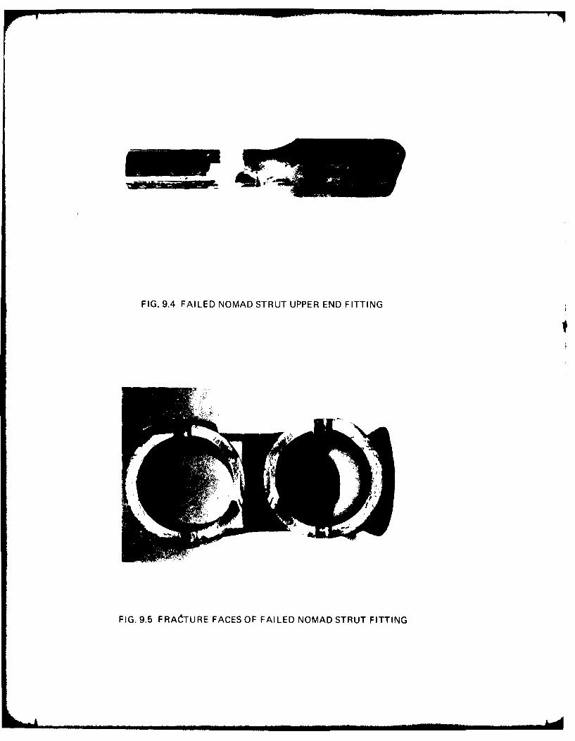
FIG. 9.4 FAILED NOMAD STRUT UPPER END FITTING
FIG. 9.5 FRACTURE FACES OF FAILED NOMAD STRUT FITTING

ad I,--,
FIG. 9.6 CT4-A IN FLIGHT TEST CALIBRATION LOADING RIG

-TE ME -T MSVA - orston
t~l Bending
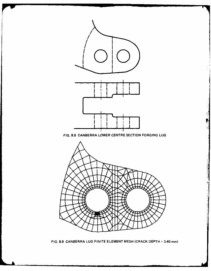
' 0
4 I
FIG. 9.8 CANBERRA LOWER CENTRE SECTION FORGING LUG
FIG. 9.9 CANBERRA LUG FINITE ELEMENT MESH (CRACK DEPTH =3.40 mm)

Nuj
w
I-w
LLJ
LL
00

L IL
LL_ Ln+ mr
W- LUL LA
+ I. LLA
q- LA_
%Z L L) L
401 LA
LA ex
xI L Li)
LL LL n-
-y -n -_ - ,
-t- -
LA V)0
LxLU
L- -
U- z
U.
0 3z
-AJ
LA.' LA.o~-J
o 0J
Z0 -J
L C) -.
U_ -
0 + + 0L
Li) LA_
ui o 0 Ln
U- U- U- U- U..
PSI)SS38S IVIW0
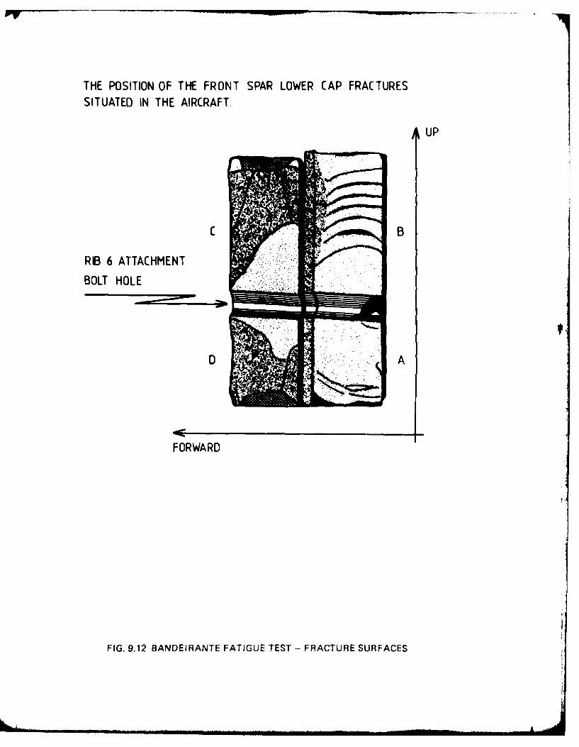
THE POSITION OF THE FRONT SPAR LOWER CAP FRACTURESSITUATED IN THE AIRCRAFT.
UP
CB
RIB 6 ATTACHMENTBOLT HOLE
FORWA RD
FIG. 9.12 BANDEIRANTE FATIGUE TEST - FRACTURE SURFACES

w
0
00
C-)
wn u
-J
LL
CVCi(WW) Hd3O AM

CRACKED WINGPLANKS
ALL MAT'L 7075-T6
RIB CAP SKIN PLANK-140
218- 'SECTION A-A
-- SPLICE PLATE
-,-- TYPICAL FATIGUE
-25 LOCK NUTS. CRACK LOCATION IN
13 EACH SIDE PLANK 14"
LOWER SURFACE WIDTH
A ^' AT- ______-T
VIEW LOOKING NORMAL TO SPLICE
B.L.65FIG. 9.14 LOWER SURFACE SPLICE JOINT - LOCKHEED L188 ELECTRA

FIG. 9.15 WESTLAND WESSEX ROTOR BLADE FATIGUE CRACK

.
I . "I.F I
FIG. 9.16 BELL MAIN ROTOR BLADE TENSION/TORSION RETENTION STRAP
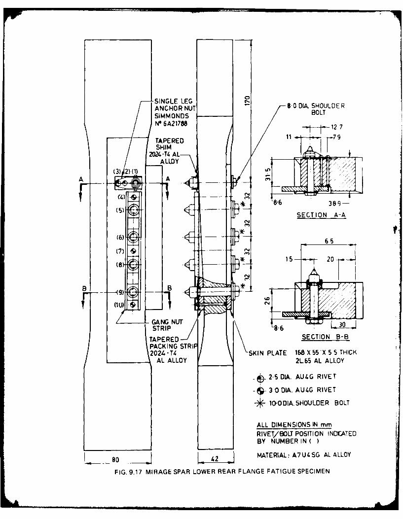
-SINGLE LEG 800,.SOLEANCHOR NUTSOA.SULESIMMO0ND S BOLTNO 6A21788 127
TAPERED 91SHIM
2024 -T4 A LALLOY
(3) 2)(1)A A
(4) 8-6389-
(5) SECTION A-A
65 -
*15 - 20
B -B *,
(1 U)
GANG NUr 3STRIP86
TAPE RED SECTION B-BPACKING STRIP2024.-T4 SKIN PLATE 168 X55'X 5 THICK
AL ALLOY 21-65 AL ALLOY
~.5 D&. AUI.G RIVET
3~ 30 DIA. AUI.G RIVET
*1O-ODIA. SHOULDER BOLT
ALL DIMENSIONS IN mmRIVEV/BOLT POSITION INDICATEDBY NUMBER IN
80 42MATERIAL: A7 U4 SG AL ALLOY
F IG. 9.17 MIRAGE SPAR LOWER REAR FLA NGE FATI GUE SPECIMEN

FIG. 9.18 SPECIMEN GKlC6, 2.5 mm RIVET CONTROL SPECIMEN -LIFE 7342 FLIGHTS
FIG. 9.19 SPECIMEN GKIC8, 0.3% INTERFERENCE FIT BUSH11 mm OUTSIDE DIAMETER - LIFE 14242 FLIGHTS

10 u- A-
<' u
U U
~J 4 ' 0
(P W
Ch-
u- Zo11 I;L
&D V +u.J o ogoV
C-. + LL
47*~ u , 2 1j4 --
o I-U u
Q 4 4<~d -g~% - I
o -O It .0
~~d' +vqo~
co x'D I +I - 0
v2 0I ~O 4 'd uC
LI .1) I CD
Vi lpj
o'm u , - u C-
-J -J
J LLL
j <1w IPk.
La 09)0

A 14L Fl I ~LI. st
0', tro 1 o~ vt f
FIG. 9.21 FINISHED BFRP PATCH, COMPLETE WITH EXTERNAL ENVIRONMENTALPROTECTION IN POSITION ON A MIRAGE WING
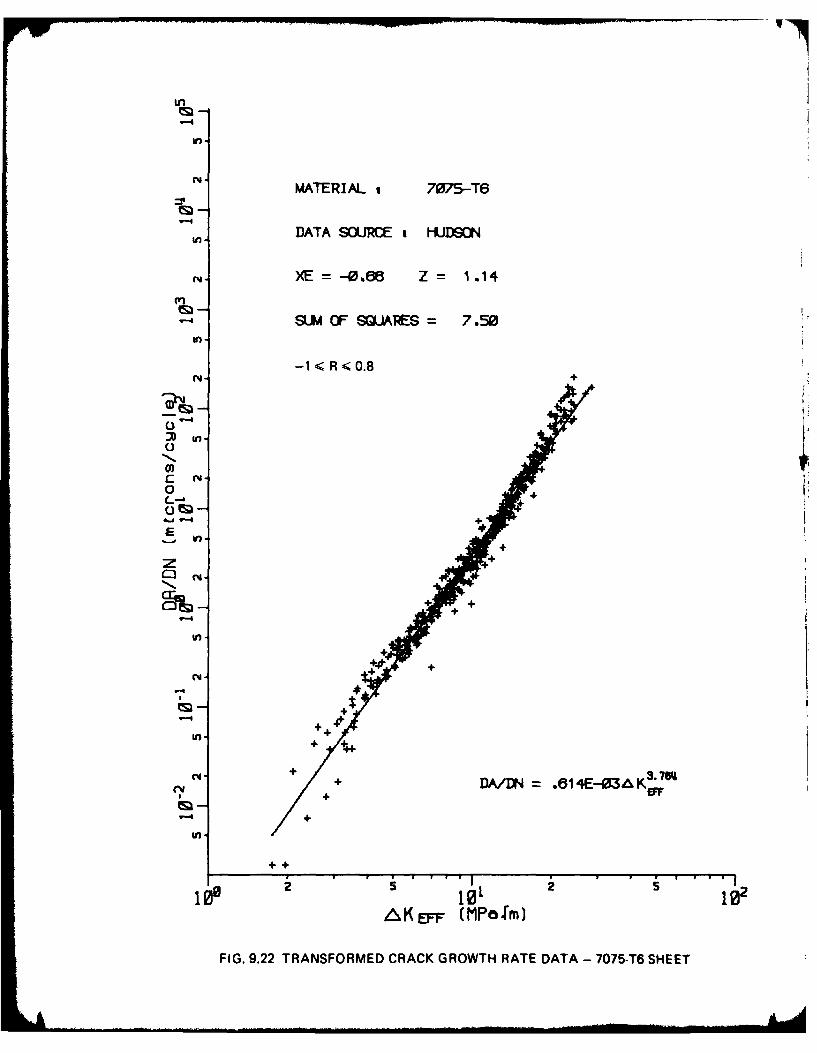
In
-4olMATERIAL t 7075-T6
DATA SOURE IHUDSON
XE = -0.86 Z 1.14
SUM OF QLARES = 7.50
-1 R < 0.8
(3
0 "
C rm'0 +
+ ,
10 4.§~ : 4.
L
in -+
"M- +,0+
+4
+
DA/UN= .814E-03i&Kff
1loll 101i 102
A K EFF (MPa 1m)
FIG. 9.22 TRANSFORMED CRACK GROWTH RATE DATA - 7075-T6 SHEET

BOEING 707 (BOAC)KRTNES (19743
VISCOUNT (NZNAICJKRYNES 19723
COMET 4SKRYNES E19711
BOEING 727 (TIRRHUNTER AND FETNER 11967J
BOEING 727 [RNSETT]HUNTER AND FETNER 11967J
CRNBERIRWELLS (19663
VI SCOUNTVISICK (1965J
S-CONSTELLRITION (PACIFICHERTH SMITH (1959)5-CONSrELLRTIOJN (FAR ERiS
HEATH SMITH (1959)
5- CONSTELLRT ION (I NOIFNHEAYH SMIrH (1959)
SUPER-CONSTELLRTION (RUSHEATH SMITH (19592
BRISTOL FREIGHTER IN.7.)HEATH SMITH (19583
VISCOUNTDBRCON (19563
BRISTOL FREIGHTERBAUM AND HOOKE (19533
I I I I I
.30 10.009 20.00 30.00 U2,.00 50.09 60.03HEIGHT - KILO FEET
FIG. 9.23 GUST DATA AVAILABLE FROM VARIOUS MEASUREMENT PROGRAMS
=oi

.. A ircraft w ith z; Icloud warningradar
Aircraft withoutcloud warning
; = radar
i-7 LIO = distance between
05@ gust encountersV1 of magnitude In0 (10 feet per second
or greater(nautical miles)06
1 -BRISTOL FREIGHTER _2 -V I SCOUNT -3-BRISTOL FREIGHTER (N.Z.)L- SUPER-CONSTELLRTION (RUS
in 5-S-CONSTELLRTION (INDIRN6-S-CONSTELLRTION (FRR ERS7- S-CONSTELLRTION (PRCIFIC8 -V I SCOUNT9- CRNBERRR
10- BOEING 727 (RNSETT)11-BOEING 727 (TRR)
10.01 20.01 31.U 40.S 50.09 60.19HEIGHT - KILO FEET
FIG. 9.24 VARIATION OF DISTANCE BETWEEN 10 F.P.S, GUSTS WITH ALTITUDE

FiG 9.25 AFDASSTRAIN RANGEPAIR COUNTERINSTALLATION INMIRAGE AIRCRAFT
FIG. 9.26 AFDAS -STRAIN RANGEPAIR COUNTERINTERROGATIONUNIT

2 1
3 21
4 3]
5 4 4
6 19 15 3 148 5
7 6 10 6 53 168 61
8 4 3 2 52 51 62 7
: 9 5 5 1 20 26 14 9 8
10 7 7 2 22 15 8 11 13 9
11 5 3 5 3 1 10
12 1 1 11
13 1 1 12
14 13
15 1]
FIG. 9.27 SAMPLE FORMAT OF RANGE MEAN PAIR COUNTS

DISTRIBUTION
COPY NO.
AUSTRALIA
Department of Defence
Central Office
Chief Defence Scientist 1Deputy Chief Defence Scientist 2
Superintendent, Science & Technology Programs 3Australian Defence Scientific & Technical Representative (UK) -
Counsellor, Defence Science (USA)Joint Intelligence Organisation 4Defence Central Library 5Document Exchange Centre, D.I.S.B. 6-22
Aeronautical Research Laboratories
Chief Superintendent 23Superintendent, Structures Division 24Divisional File, Structures 25Author: G.S. Jost 26Mr. J.Y. Mann, Structures Division 27
Dr. D.G. Ford, " " 28Mr. C.K. Rider " " 29
Mr. C.A. Patching " 30
Mr. B.C. Hoskin, " 31
Dr. J.M. Finney, " 32
Dr. J.G. Sparrow, 33Dr. R. Jones, 34
Mr. P.J. Howard, 35
Mr. J.M. Grandage, " 36
Dr. G.S. Jost, (For ICAF Distribution) 37-261Mr. C.K. Rider (For TTCP Distribution) 262-266
Dr. F.H. Hooke (For CAARC Distribution) 267-270
Superintendent, Materials Division 271
Dr. A.A. Baker, " 272
Dr. N.E. Ryan, " 273
Mr. L.M. Bland, " 274
Library 275
Materials Research Laboratories
Library 276
Defence Research Centre, Salisbury
Library 277
Central Studies Establishment
Information Centre 278
.. ./contd.
DISTRIBUTION (CONTD.)
COPY NO.
Engineering Development Establishment
Library 279
RAN Research Laboratory
Library 280
Navy Office
Naval Scientific Adviser 281Directorate of Naval Aircraft Engineering 282
Army Office
Army Scientific Adviser 283Royal Military College Library 284
Air Force Office
Aircraft Research & Development Unit,
Scientific Flight Group 285Air Force Scientific Adviser 286Technical Division Library 287-290DGAIRENG 291-292HQ Support - Command (SENGSO) 293
Department of Industry & Commerce
Government Aircraft Factories
Manager 294
Library 295
Victorian Region
Library 296
Department of Transport
Secretary 297Library 298Airworthiness Group, Mr. K. O'Brien 299Airworthiness Group, Mr. R.B. Douglas 300Airworthiness Group, Mr. G.P. Esson 301
Australasian ICAF Distribution
Mr. R.C. Beckett, Commonwealth Aircraft Corporation 302Mr. C. Torkington, Principal Airworthiness Engineer 303
(Fatigue), Airworthiness Branch, Dept. of TransportMr. T.F. Harvey, Technical Librarian, Trans-Australia 304
AirlinesMr. G.D. Bennett, Chief Engineer, Government Aircraft Factories 305Mr. J.H. Bibo, Technical Manager, Ansett Airlines of Australia 306
Mr. H.K. Millicer 307
../contd.

DISTRIBUTION (CONTD.)
COPY NO.
Australasian ICAF Distribution (contd.)
New South Wales
Mr. J.M. Whitney, Chief Aeronautical Engineer,Hawker de Havilland Australia, Pty. Ltd., Bankstown 308
Mr. R.H. Stevens, Chief Structures Engineer, Qantas,Qantas Jet Base, Mascot 309
New Zealand
Mr. J.E.C. Shearer, Departmental Librarian,
Department of Mech. Eng., University of Canterbury 310Mr. D.J. O'Brien, Chemistry Division,
Derartment of Scientific and Industrial Research, Petone 311Mr. E.T. Labett, Civil Aviation Division,
Department of Transport 312
SPARES 313-325

ATE
,Q4