Embed Size (px)
Citation preview
Laboratory Tests of Sealers for Sawed Joints WILLIAM H. KUENNING, Senior Development Engineer Products and Applications Development Section, Portland Cement Association, Chicago, Illinois
The performance of sealing materials for sawed joints is being studied by a laboratory test in which the joints are opened and closed at speeds of the order of '732 in. per hr. The sealers are applied to sawed joints which are initially Va or in, wide and which are usually opened an additional ya in. at 0 F during the tests. This test procedure appears to be more severe than method 223. 11 of Federal Specification SS-R-406C. Tests have been conducted on conventional sealers as well as on materials which are still in the development stage or which have been developed for other applications.
The results have shown that extensibility is not strictly an inherent property of the material, but is highly dependent on the relative dimensions of the cross-section of the sealer, referred to as the "shape factor." The importance of the shape factor indicates the desirability of developing suitable elastomers in shapes or forms that would avoid the high stress concentrations which cause bond failures. Foams or hollow shapes might satisfy these requirements. The conclusion is drawn that initial joint widths must be designed in relation to the joint sealer material, the joint spacing, and the climate.
Although material costs of some potentially useful sealers are high, they may not be high in terms of lifetime performance.
The work reported covers the period 1955 through 1957 and is part of a continuing program.
#IN 1955 a program of tests was started at the Portland Cement Association laboratories directed toward finding a sealer that would be more satisfactory for use in sawed joints than those now commercially available.
Discussions at that time with a number of manufacturers of plastics and rubbers who supplied materials which they considered to have potential value as joint sealers placed no maximum limitation on cost. Since then, approximately 70 samples have been received, representing about a dozen different types of material. Some of these were found almost immediately to be unsuitable. Others were found to be of considerable interest, even though costs of some are higher than those of presently used sealers.
The initial inquiries to manufacturers requested materials which would be capable of undergoing deformations of at least 100 percent in Vs-in. wide joints at a temperature of 0 F . Materials were received from a number of manufacturers who expressed confidence that their products were not only reasonably insensitive to temperature but would undergo "elongations" of 300 or 350 percent, far in excess of the stated requirements. When tested on the machine shown in Figure 1, however, either at 73 F or 0 F , some of these materials failed from increases in joint width of only 50 to 80 percent, values which are at great variance with the performance predicted on the basis of other test methods. This difference is due, at least in part, to a testii^ factor which in the compression-testii^ of elastomers has become known as the shape factor. The same term is used here, even though concern is with tension rather than compression.
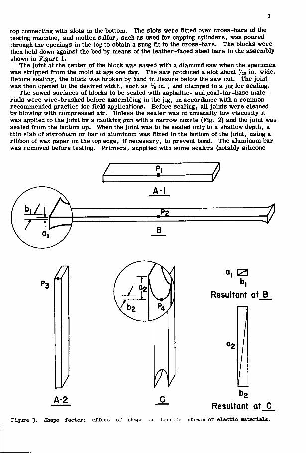
SHAPE FACTOR Figure 3 represents one concept of the effect of the shape factor on the tensile strain
of elastic materials. If a rubber shape such as A-1 is to be stretched 100 percent longitudinally, the point P i will then appear at the position P2 in B. To get to this point
1
2
it has moved through the resultant of the vertical distance ai and the horizontal distance hi. If these two distances were magnified six times and the resultant plotted, it would be as shown in the small rectangle. However, if this same piece of material is tipped up on end, as at A-2, and a new point, P3, is chosen on a top edge, stretchii^ this material in a direction parallel to the shortest dimension of the piece moves P3 to the point P4. It has traveled through the resultant of the vertical distance aa and the horizontal distance b2. If these distances also are magnified six times and plotted, the new resultant shown in the lower rectangle is obtained. This resultant is tremendously large compared to the resultant in B. In both cases the material has been stretched 100 percent, but in the second case the stress concentrations at P4 and at any point on the surface are very great. |
From this illustration, it is obvious that in pavement joints the materials are being stretched in the least favorable direction
i
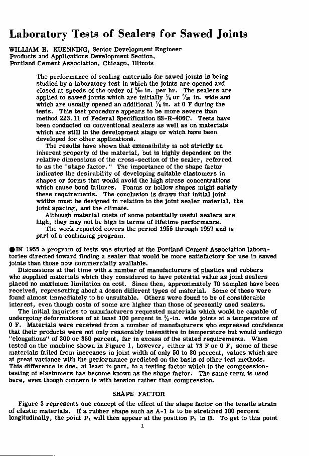
Figure 1. Machine for sealers.
testing joint
Figure 2. Gun for sealing Joints.
Extensibility of elastomers and other materials, determined by stressing them longitudinally, may be referred to as "elongation." To avoid confusion with this type of measurement, the term "deformation" has been used herein when referring to the stretching of sealers in concrete joints.
MATERIALS AND EQUIPMENT Testing Equipment
Figure 1 shows a testing machine built in the PCA laboratory for testing sealers for sawed joints. By means of a 28,736-to-l speed reducer, a 32-thread-per-inch screw, and an appropriate pulley combination, the speed of a 1750-rpm motor is translated into a speed of approximately y32-in. -per-hr travel in the movable bed. One end of each of three 2/4- by 4- by 16-in. concrete blocks is clamped to a fixed bed, and other end being clamped to the movable bed. The blocks contain sawed joints, which were in most cases
in. wide and 2 in. deep. Micrometer heads mounted in the arm on the side of the carriage, which come to bear against the two limit switches in the foreground, control the ultimate distance of travel in either direction. The machine, mounted on casters for ease of transfer, may be operated either in laboratory air at 73 F or in a walk-in freezer at 0 F . The speed of 732 in. per hour was chosen because it represents a travel rate per hour of 25 percent of the initial joint width, which is comparable to that used in the standard ASTM and Federal specification bond tests for joint sealers. The speed can, however, be modified by changing the pulley combinations.
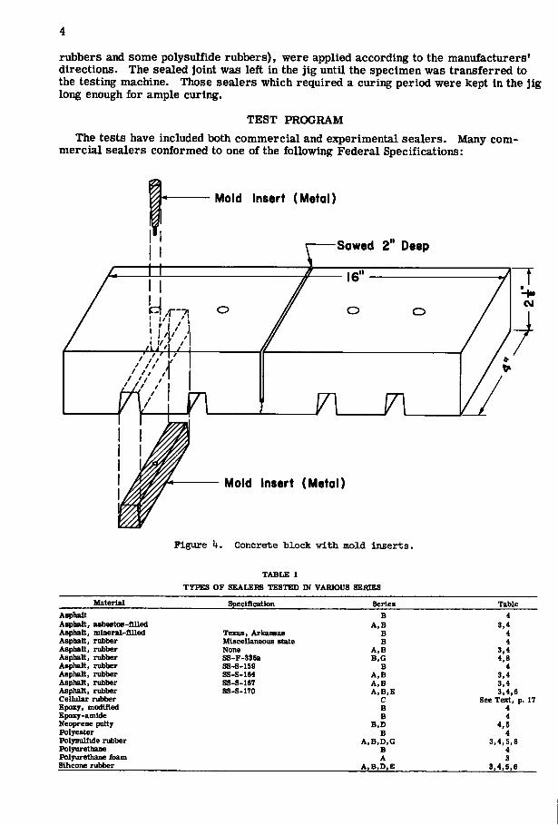
Preparation of Specimens Concrete blocks, 272- by 4- by 16-in. (Fig. 4) were made of a 6-sack mix using an
aggregate of 74-in. maximum size. The concrete, with a slump of 2 to 4 in. and an air content of 3. 5 to 7 percent, was placed in the molds with vibration. The blocks were cured 7 days in the moist room, then stored at 73 F and 50 percent relative humidity. Flexural strengths of 29 batches of concrete at 7 and 28 days were in the ranges 480 to 610 psi and 520 to 880 psi, respectively, and compressive strengths were in the ranges 3,250 to 4,460 psi and 5,000 to 6,520 psi, respectively.
The concrete blocks were lightly reinforced with Yt-in. steel wires in each end but not crossing the joint. The blocks were made in wood molds containing metal inserts of the shape shown in Figure 4. The finished blocks contained tapered openings in the
top connecting with slots in the bottom. The slots were fitted over cross-bars of the testily machine, and molten sulfur, such as used for capping cylinders, was poured through the openings in the top to obtain a snug fit to the cross-bars. The blocks were then held down against the bed by means of the leather-faced steel bars in the assembly shown in Figure 1.
The joint at the center of the block was sawed with a diamond saw when the specimen was stripped from the mold at age one day. The saw produced a slot about Vw in. wide. Before sealing, the block was broken by hand in flexure below the saw cut. The joint was then opened to the desired width, such as in., and clamped in a jig for sealing.
The sawed surfaces of blocks to be sealed with asphaltic- and,coal-tar-base materials were wire-brushed before assembling in the jig, in accordance with a common recommended practice for field applications. Before sealing, all joints were cleaned by blowing with compressed air. Unless the sealer was of unusually low viscosity it was applied to the joint by a caulking gun with a narrow nozzle (Fig. 2) and the joint was sealed from the bottom up. When the joint was to be sealed only to a shallow depth, a thin slab of styrofoam or bar of aluminum was fitted in the bottom of the joint, using a ribbon of wax paper on the top edge, if necessary, to prevent bond. The aluminum bar was removed before testing. Primers, supplied with some sealers (notably silicone
1 A-l
B
A-2
a, 13
Resultant at B
ag
b2
Resultant at C Figure 3. Shape factor: effect of shape on tensile strain of e l a s t i c materials.
rubbers and some polysulfide rubbers), were applied according to the manufacturers' directions. The sealed joint was left in the jig until the specimen was transferred to the testing machine. Those sealers which required a curing period were kept in the jig long enough for ample curing.
TEST PROGRAM The tests have included both commercial and experimental sealers. Many com
mercial sealers conformed to one of the following Federal Specifications:
Mold Insert (Metal)
Sawed 2 Deep
Mold Insert (Metal)
Figure k. Concrete block with mold inserts.
TABLE 1 TYPES OF SEALERS TESTED W VARIOUS SERIES
Material Specification Series Table Asplialt B 4 Asphalt, asbestos-flUed A,B 3,4 Asphalt, mineral-filled Texas, Arkansas B 4 Asphalt, rubber Miscellaneous state B 4 Asphalt, rubber None A,B 3,4 Asphalt, rubber SS-F-336a B,G 4,8 Asphalt, rubber ss-s-isg B 4 Asphalt, rubber SS-S-164 A,B 3,4 Asphalt, rubber SS-S-167 A,B 3,4 Asphalt, rubber SS-S-170 A,B,E 3,4,6 Cellular rubber C See Text, p. IT Epoxy, modified B 4 Epoxy-amide B 4 Neoprene putty B,D 4,5 Polyester B 4 Polysulfide rubber A,B,D,G 3,4,5,8 Polyurethane B 4 Polyurethane foam A 3 Silicone rubber A,B,D,E 3,4,5,6
SS-S-159 A mastic-type sealer. May have either one or two components.
SS-F-336a A hot-applied, one-component sealer. This specification has been replaced by SS-S-164.
SS-S-164 A hot-applied, one-component sealer. This specification replaces SS-F-336a.
SS-S-171 Mineral-filled sealer containing dia-tomaceous earth.
SS-S-167 Hot-applied, one-component jet-fuel-resistant (JFR) sealer.
SS-S-170 Cold-applied, two-component, JFR sealer.
An index of the test materials is provided in Table 1. A summary and comparison of the test procedures used in the various series, together with a statement of their purposes, is given in Table 2.
Because of the limited capacity of the testing machine and the time required for a single cycle, only one specimen per sealer was used for most tests. Although this procedure might be considered unfair to sealers which happened to fail early, the test results establish definite trends and indicate which classes of sealers are most worthy of further study.
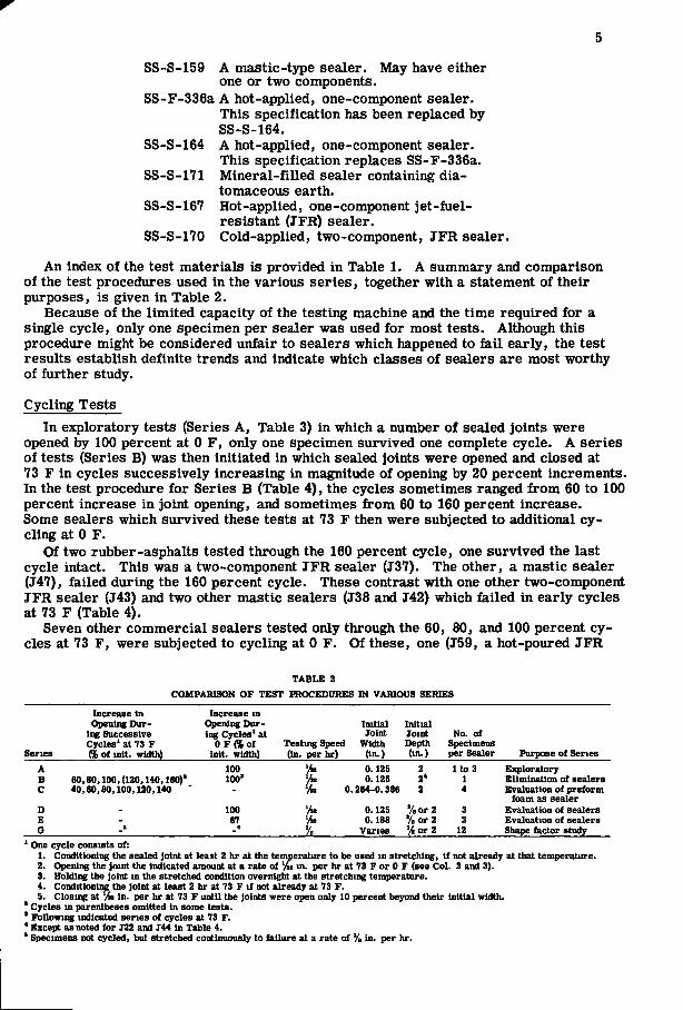
Cycling Tests In exploratory tests (Series A, Table 3) in which a number of sealed joints were
opened by 100 percent at 0 F , only one specimen survived one complete cycle. A series of tests (Series B) was then initiated in which sealed joints were opened and closed at 73 F in cycles successively increasing in magnitude of opening by 20 percent increments. In the test procedure for Series B (Table 4), the cycles sometimes ranged from 60 to 100 percent increase in joint opening, and sometimes from 60 to 160 percent increase. Some sealers which survived these tests at 73 F then were subjected to additional cycling at 0 F.
Of two rubber-asphalts tested through the 160 percent cycle, one survived the last cycle intact. This was a two-component JFR sealer (J37). The other, a mastic sealer (J47), failed durii^ the 160 percent cycle. These contrast with one other two-component JFR sealer (J43) and two other mastic sealers (J38 and J42) which failed in early cycles at 73 F (Table 4).
Seven other commercial sealers tested only through the 60 , 80, and 100 percent cycles at 73 F , were subjected to cycling at 0 F . Of these, one (J59, a hot-poured JFR
TABLE 2 COMPARISON OF TEST PROCEDURES IN VARIOUS SERIES
Increase in Increase m Opening Dur Opening Dur Initial Initial
ing Successive ing Cycles* at Joint Joint No. of Cycles' at 73 F O F f f i o f Testing Sped i Width Depth Specimens
Series (% of init. width) inlt. width) (in. per hr) (in.) (in.) per Sealer Purpose of Series A 100 0.125 2 l t o 3 Exploratory B 60,80,100, (120,140,160)' 100' 0.12S 2* 1 Elimination of sealers c 40,60,80,100,120,140 - 0.264-0.386 2 4 Evaluation of preform
foam as sealer D - 100 0.125 '/a or 2
'/Bor2 3 Evaluation of sealers
E - 67 '^ %
0.188 '/a or 2 '/Bor2 3 Evaluation of sealers
G _s _5 '^ % Varies */4or2 12 Shape factor study
' One cycle consists of: 1. Conditioning the sealed Joint at least 2 hr at the temperature to be used in stretching, i f not already at that temperature. 2. Opening the Joint the indicated amount at a rate of % m. per hr at 73 F or 0 F (see Col. 2 and 3). 3. Holding the Joint in the stretched condition overnight at the stretching temperature. 4. ConditioniiK the Joint at least 2 hr at 73 F i f not already at 73 F. 5. Closing at % in. per hr at 73 F until the Joints were open only 10 percent beyond their initial width.
' Cycles in parentheses omitted in some tests. * Following indicated series of cycles at 73 F. * Except as noted for J22 and J44 in Table 4. ' Specimens not cycled, but stretched continuously to failure at a rate of % in. per hr.
6
rubber-asphalt) failed in the fifth 0 F cycle, one (J57, a hot-poured rubber-asphalt) in the fourth, and one (J58, a solvent-system rubber-asphalt) in the second. One other hot-poured rubber-asphalt (J36) had not failed in adhesion or cohesion by the end of the first 0 F cycle, but it had become badly deformed in the first and second 73 F cycles. An asphalt (J26), a mineral-filled asphalt (J39), and a rubber-asphalt (J6) failed in the first 0 F cycle. The performance of commercial sealers as a group was quite variable, but it is likely that if more specimens of each sample had been tested the performance would have been variable for any one sealer. (Note, for example, the differences between sealer J43 in Table 4 and the same sealer in Table 6.)
Two samples of Neoprene putties survived cycling at 73 F through the 160 percent cycle, and two others through the 140 percent cycle. One Neoprene putty (J33), which had been through the 160 percent cycle, did not fail during a subsequent cycle at 0 F , after which it was taken off test. These sealers, as well as the rubber-asphalts, are subject to some permanent, irregular deformation of the exposed surfaces.
A polyester cauUc (J20) also survived cycling at room temperature through the 160 percent cycle, then failed in the first cycle at 0 F .
One silicone rubber (J18-3) failed in the 100 percent cycle at 73 F. This failure occurred on standing overnight in the stretched condition.
A black polysulfide rubber (J22) failed in the 80 percent cycle at 73 F . A new sample (J44) of gray polysulfide rubber with approximately similar properties and obtained from the same manufacturer, was used in preparing three specimens in which the joints were not sealed to the full depth. One was sealed to a depth of % in. and one to a depth of % in. A third was sealed along the top of the saw cut to a depth of V* in. and along each end to a horizontal distance of ys in. These three specimens failed in either the 140 or 160 percent cycles, showing that this sealer can be deformed farther before failure if it is placed in the joint to shallow depths, a result which should be expected from the effect of the shape factor.
The epoxy amide sealers, modified epoxy sealer, and urethane sealers failed in the first cycle. The suppliers of these experimental sealers are investigating new formulations of these materials.
TABLE 3 SERIES A TESTS OF JOINT SEALERs'*'
Type of Material
Laboratory Sample
No.
Number of
Specimens Spec, or other Description Type of Failure
Asphalt, asbestos-filled J24 1 Adhesion
Asplialt, rubber
T6 J37' 137 T61 J61A*
j SS-S-164 SS-S-170 SS-S-170 Solvent system Solvent system
Adhesion Cohesion, adhesion
Adhesion Adhesion Adhesion
Polysulfide rubber
J l
J2
J22 ;
Black, two component cold-applied'
Black, two component, cold-applied'
Gray, two component, cold-applied'
Tension in concrete'
Cohesion
Adhesion
Polyurethane foam J21 Foamed-in-place rubber Cohesion' 117 1 Red, two component. Adhesion
Silicone rubber J18 cold-applied'
White, two component, cold-applied'
' Al l Joints initlaUy y,-in. wide, sealed to fiUl depth of 2 in. Test Procedure: 1. Sealed Joint opened to 100 percent Increase in initial width at rate of %> In. per hr at 0 F. 2. Joint held in stretched condition overnight at 0 F. 3. Joint conditioned 2 hr at 73 F. 4. Joint closed at 73 F at same rate of speed to 10 percent increase in initial width.
' Al l specimens except one failed in first cycle. ' Sealed by manufacturer. * Adhesive asphalt applied to concrete before sealing. ' High modulus sealer, did not fai l ; concrete biled in tension. • Primer furnished. ' No primer furnished. ' FaUed during thawing. ' One specimen did not faiL
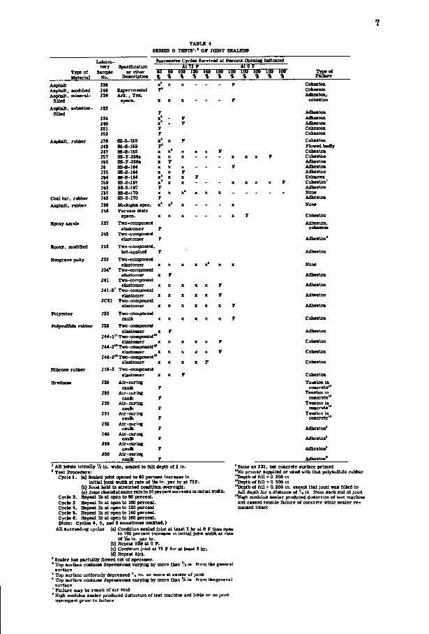
TABLE 4 SEKIEB B TESTS*'* OF JOINT SEALERS
SiicccBalTe Cycles Survived at Percent Opening Indicated Tjpeof Material
Asphalt Asphalt, modified Asphalt, mineral-
flUed Asphalt, asbestos-
flUed
Asphalt, rubber
Coal tar, ruliber Asphalt, rubber
Epoxy amide
Epoxy, modified
Neoprene putty
tory Specification At 73 t At OF Sample or otlier ItO u 100 120 140 leo lU IM 100 lU 100 Type of
No. Description % % % % % % % % % % % Failure 126 x" X X _ _ _ F Cohesion 146 Experimental CoheBion T39 Ark., Tex. Adhesion,
specs. X X X - - - F cohesion J23
F Adhesion T24 x' - F Adhesion 140 x' - F Adhesion ISl F Cohesion J52 F Cohesion T38 SS-S-159 x' X F Cohesion T42 SS-S-159 F* Flowed badly 147 SS-S-159 X X* X X z F Cohesion 157 SS-F-33Sa X X X - - - X z z F Cohesion 160 SS-F-33ea X F Adhesion 16 SS-B-164 X X X F Adhesion T3S SS-S-164 X X F Adhesion 164 S8-S-164 x' X X F Unknown ISO SS-S-167 X* X X - - - z Z X X F Cohesion J63 SS-B-ie7 F Adhesion 137 SS-S-170 X X x' z X X None J43 SS-B-170 F Adhesion J36 Michigan spec. x' x" z - - - X None T5B Various state
specs. X X X - - - X F Cohesion 127 Two-component Adhesion,
elastomer F cohesion T45 Two-component
elastomer F Adhesion' T53 Two-component,
hot-applied F Adhesion 733 Two-component
elastomer X X X X X* X X None J34' Two-component
elastomer X F Adhesion T41 Two-component
elastomer X X X z X F Adhesion 141-2 Two-component
elastomer X X X z z F Adhesion IC41 Two-component
elastomer X X X z X X F Adhesion J20 Two-component
caulk X z z z z z F Cobeslon Polyester Folysulflde nibbep J22 Two-component
elastomer T44-1" Two-component*"
elastomer 144-2" Two-component"
elastomer J44-3" Two-component"
elastomer Silicone rubber H8-3 Two-component
elastomer z 728 Alr-curlng
caulk F 729 Air-curing F 730 Alr-curlng
caulk F 731 Air-curing
caulk F 732 Air-curing
caulk F 748 Air-curing
caulk F 74g Alr-curlng
caulk F 750 Alr-curlng
caulk F
Adhesion Cohesion Cohesion Cohesion
Cohesion Tension In concrete**
Tension in concrete**
Tension In concrete**
Tension In concrete**
Adhesion' Adhesion' Adhesion' Adhesion' ' AU joints Inttlally */< in. wide, sealed to full depth of 2 in.
' Test Procedure: Cycle 1. (a) Sealed joint opened to 60 percent increase In
Initial Joint width at rate of 'M In- per hr at 73F. (b) loid held In stretched condition orernlght. (c) Joint closed at same rate to 10 percent increase m initial width.
Cycle 2. Repeat lb at open to 80 percent. Cycle 3 Repeat lb at open to 100 percent. Cycle 4. Repeat lb at open to 180 percent Cycle 5. Repeat lb at open to 140 percent. Cycle 6. Repeat lb at open to 160 percent. (Note: Cycles 4, 5, and 6 sometimm omitted.)
All succeeding cycles (a) Condition sealed )olnt at least 2 hr at 0 F then open to 100 percent Increase in initial joint width at rate of in. per hr.
(b) Repeat 1(b) at 0 F. (c) Condition Joint at 73 F for at least 2 hr. (d) Repeat 1(c).
' Sealer has partiaUy flowed out of specimen. * Top surface conlaiiis depressions varying by nure than % ui from the general surface
' Top surface uniformly depressed *• in. or more at center of joint ' Top surface contains depressions varying by more than V« In from the general surface
^ Failure may be result of air void ' High modulus sealer produced distortuin of test machine and little or no joint movement prior to failure
' Same as J33, but concrete sur&ice primed *'No primer supplied or used with this polysulfide rubber •*Depth of fill = 0 250 in "Depth of fill - 0 500 in "Depth of fill = 0.250 in. except that Joint was fiUed to full depth for a distance of */• in from each end of jomt
**High modulus sealer produced distortion of test machine and caused tensile failure of concrete while sealer remained Intact
8
TABLE 5 SERIES D TESTS ' . ' OF JOINT SEALERS
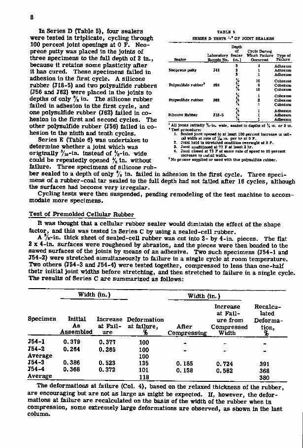
In Series D (Table 5), four sealers were tested in triplicate, cycling through 100 percent joint openings at 0 F . Neo-prene putty was placed in the joints of three specimens to the full depth of 2 in., because it retains some plasticity after it has cured. These specimens failed in adhesion in the first cycle. A silicone rubber (J18-5) and two polysulfide rubbers (J56 and J62) were placed in the joints to depths of only % in. The silicone rubber failed in adhesion in the first cycle, and one polysulfide rubber (J62) failed in cohesion in the first and second cycles. The other polysulfide rubber (J56) failed in cohesion in the ninth and tenth cycles.
Series E (Table 6) was undertaken to determine whether a joint which was originally ^M - in . instead of Va-in. wide could be repeatedly opened % in. without failure. Three specimens of silicone rubber sealed to a depth of only % in, failed in adhesion in the first cycle. Three specimens of a rubber-coal tar sealed to the full depth had not failed after 16 cycles, although the surfaces had become very irregular.
Cycling tests were then suspended, pending remodeling of the test machine to accommodate more specimens.
Depth of Cycle During
laboratory Sealer Which Failure Type of Sealer Sample No. (in.) Occurred Failure
2 1 Adhesion Neoprene putty 141 2 1 Adhesion
2 1 Adhesion % 10 Cohesion
Polysuliide rubber' J56 ^ •
9 Cohesion % 10 Cohesion V. 1 Cohesion
Polysulfide rubber T62 \ 2 Cohesion \ 1 Cohesion % 1 Adhesion
Silicone Rubber JlS-5 % 1 Adhesion % 1 Adhesion
AU Joints initially y.-in. wide, sealed to depths of % in. or 2 in. ' Test procedure:
1. Sealed joint opened to at least 100 percent increase in initial width at rate of '/» in. per hr at 0 F.
2. Joint held in stretched condition overnight at 0 F. 3. Joint conditioned at 73 F at least 2 hr. 4. Joint closed at 73 F at same rate of speed to 10 percent
increase in initial width. ' No primer supplied or used with this polysulfide rubber.
Test of Premolded Cellular Rubber It was thought that a cellular rubber sealer would diminish the effect of the shape
factor, and this was tested in Series C by using a sealed-cell rubber. A %-in. thick sheet of sealed-cell rubber was cut into 2- by 4-in. pieces. The flat
2 X 4-in. surfaces were roughened by abrasion, and the pieces were then bonded to the sawed surfaces of the joints by means of an adhesive. Two such specimens (J54-1 and J54-2) were stretched simultaneously to failure in a single cycle at room temperature. Two others (J54-3 and J54-4) were tested together, compressed to less than one-half their initial joint widths before stretching, and then stretched to failure in a single cycle. The results of Series C are summarized as follows:
Width (in.) Width (in.) Increase Recalcuat Fail lated
Specimen Initial Increase Deformation ure from DeformaAs at Fail- at failure. After Compressed tion,
Assembled ure % Compressing Width % J54-1 0.379 0.377 100 _
J54-2 0.264 0.265 100 _
Average 100 J54-3 0.386 0.523 135 0.185 0.724 391 J54-4 0.368 0.372 101 0.158 0.582 368 Average 118 380
The deformations at failure (Col. 4), based on the relaxed thickness of the rubber, are encouraging but are not as large as might be expected. If, however, the deformations at failure are recalculated on the basis of the width of the rubber when in compression, some extremely large deformations are observed, as shown in the last column.
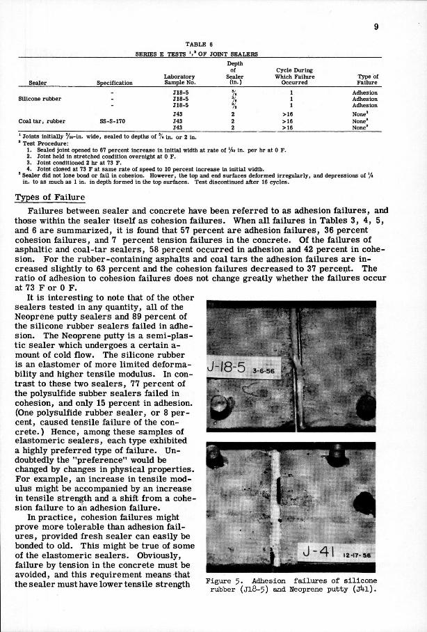
TABLE 6 SERIES E TESTS OF JOINT SEALERS
Sealer Specification Laboratory Sample No.
Depth of
Sealer (in.)
Cycle During Which Failure
Occurred Type of Failure
_ J18-5 % % 1 Adhesion
Silicone rubber - 118-5 % % 1 Adhesion
- J18-5 % 1 Adhesion J43 2 >16 None
Coal tar, rubber SS-S-170 J43 2 >16 None" J43 2 >16 None'
' Joints initially Vie-in. wide, sealed to depths of % in. or 2 in. ' Test Procedure:
1. Sealed joint opened to 67 percent increase in initial width at rate of ' ^ 2 in. per hr at 0 F. 2. Joint held in stretched condition overnight at 0 F. 3. Joint conditioned 2 hr at 73 F. 4. Joint closed at 73 F at same rate of speed to 10 percent increase in Initial width.
' Sealer did not lose bond or fail in cohesion. However, the top and end surfaces deformed irregularly, and depressions of in. to as much as 1 in. in depth formed in the top surfaces. Test discontinued after 16 cycles.
Types of Failure Failures between sealer and concrete have been referred to as adhesion failures, and
those within the sealer itself as cohesion failures. When all failures in Tables 3, 4, 5, and 6 are summarized, it is found that 57 percent are adhesion failures, 36 percent cohesion failures, and 7 percent tension failures in the concrete. Of the failures of asphaltic and coal-tar sealers, 58 percent occurred in adhesion and 42 percent in cohesion. For the rubber-containing asphalts and coal tars the adhesion failures are increased slightly to 63 percent and the cohesion failures decreased to 37 percent. The ratio of adhesion to cohesion failures does not change greatly whether the failures occur at 73 F or 0 F.
It is interesting to note that of the other sealers tested in any quantity, all of the Neoprene putty sealers and 89 percent of the silicone rubber sealers failed in adhesion. The Neoprene putty is a semi-plastic sealer which undergoes a certain a-mount of cold flow. The silicone rubber is an elastomer of more limited deforma-bility and higher tensile modulus. In contrast to these two sealers, 77 percent of the polysulfide subber sealers failed in cohesion, and only 15 percent in adhesion. (One polysulfide rubber sealer, or 8 percent, caused tensile failure of the concrete.) Hence, among these samples of elastomeric sealers, each type exhibited a highly preferred type of failure. Undoubtedly the "preference" would be changed by changes in physical properties. For example, an increase in tensile modulus might be accompanied by an increase in tensile strength and a shift from a cohesion failure to an adhesion failure.
In practice, cohesion failures might prove more tolerable than adhesion failures, provided fresh sealer can easily be bonded to old. This might be true of some of the elastomer ic sealers. Obviously, failure by tension in the concrete must be avoided, and this requirement means that the sealer must have lower tensile strength
12-17- 56
Figure 5. Adhesion falliires of silicone rubber ( j l 8 - 5 ) and Neoprene putty ( j ^ t l ) .
10
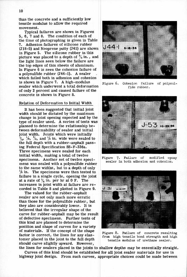
Figure 6. Cohesion failure fide rubber.
of polysul-
than the concrete and a sufficiently low tensile modulus to allow the required movement.
Typical failures are shown in Figures 5, 6, 7 and 8. The condition of each of the time of photographing is given in Table 7. Adhesion failures of silicone rubber (J18-5) and Neoprene putty (J41) are shown in Figure 5. The silicone rubber in this picture was placed to a depth of in., and the light lines seen below the failure are the top edges of thin sheets of aluminum. In Figure 6 is seen the cohesion failure of a polysulfide rubber (J44-1). A sealer which failed both in adhesion and cohesion is shown in Figure 7. A high-modulus sealer which underwent a total deformation of only 2 percent and caused failure of the concrete is shown in Figure 8.
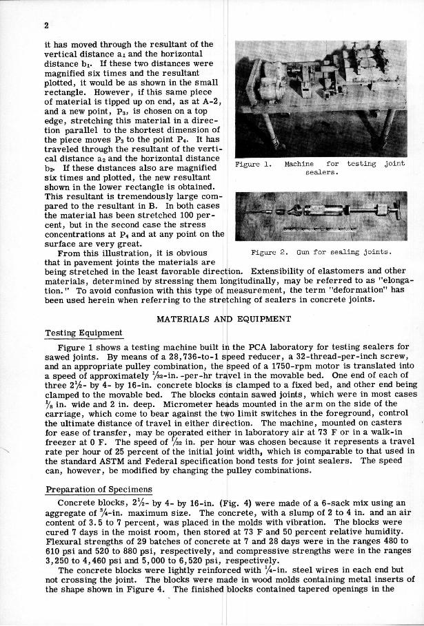
Relation of Deformation to Initial Width It has been suggested that initial joint
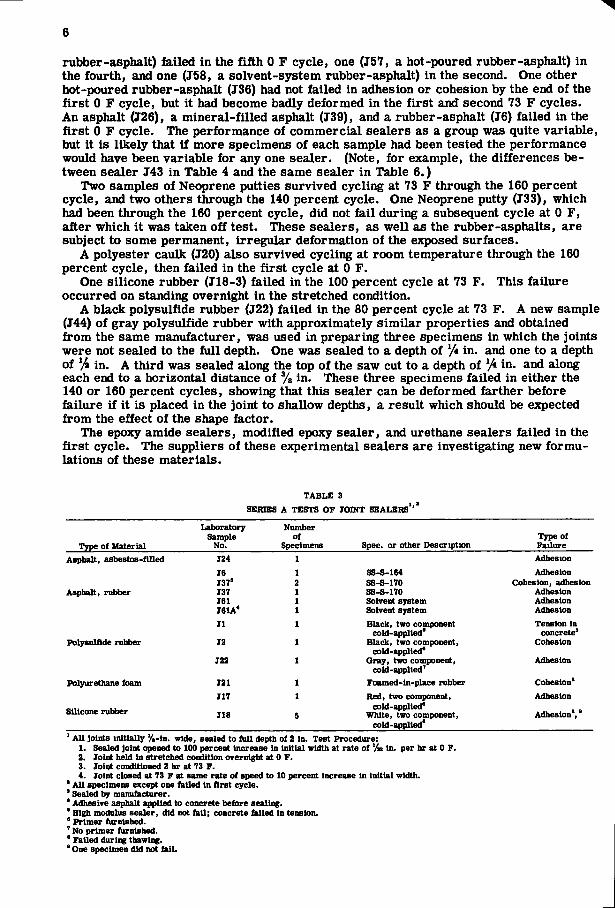
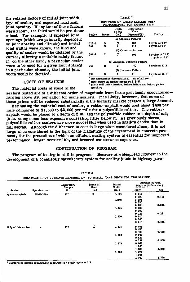
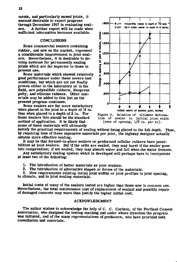
width should be dictated by the maximum change in joint opening expected and by the type of sealer used. A series of tests was planned to determine the relationship between deformability of sealer and initial joint width. Joints which were initially Vsj % j %> and ^/T. in. wide were sealed to the full depth with a rubber-asphalt passing Federal Specification SS-F-336a. Three specimens were sealed for each initial width, making a total of twelve specimens. Another set of twelve specimens was sealed with a polysulfide rubber to the same widths, but to a depth of only ^fi in. The specimens were then tested to failure in a single cycle, opening the joint at a rate of in. per hr at 0 F. The increases in joint width at failure are recorded in Table 8 and plotted in Figure 9.
The valued for the rubber-asphalt sealer are not only much more erratic than those for the polysulfide rubber, but they also are considerably lower. It is believed that the irregular shape of the curve for rubber-asphalt may be the result of defective specimens. Further tests of this kind are planned to determine the position and shape of curves for a variety of materials. If the concept of the shape factor is correct, the lines for any elastomer placed in the joint to the full depth should curve slightly upward. However, the lines for sealers placed in the joints to shallow depths may be essentially straight
Curves of this kind should be established for all joint sealer materials for use in highway joint design. From such curves, appropriate choices could be made between
23-96
Figure 7. Failure of modified epoxy sealer in both adhesion and cohesion.
Figure 8. Failiire of concrete resulting from high tensile bond strength and high
tensile modulus of urethane sealer.
11
the related factors of initial joint width, type of sealer, and expected maximum joint opening. If any two of these factors were known, the third would be pre-deter-mined. For example, if e3g)ected joint openings (which are primarily dependent on joint spacing and climate) and initial joint widths were known, the kind and quality of sealer would be dictated by the curves, allowing a suitable safety factor. If, on the other hand, a particular sealer were to be used for a given joint spacing in a particular climate, the initial joint width would be dictated.
COSTS OF SEALERS
TABLE 7 CONDITION OF FAILED SEALERS WHEN
PHOTOGRAPHED FOR FIGURES 5 to 8
Sealer
Depth Deformation of Fil l When
Series (in.) PlctuTed'(%) History (a) Adhesion Failures
J18-S D % 100 1 cycle at 0 F" J41 D 2 114 1 cycle at 0 F
(b) Cohesion Failure J44-1 C % 100 6 cycles at 73 F,
1 cycle at 0 F (c) Adhesion-Cohesion Failure
XS3 B 2 40 1 cycle at 73 F
(d) Concrete Failure J31 B 2 2' 1 cycle at 73 F ' Not necessarily deformation at time of failure. ' Date shown on picture should be 3-6-57. ' While BtiU under tension, before failure and before photo
graphing. The material costs of some of the sealers tested are of a different order of magnitude from those previously encountered— ranging above $20 per gallon for some sealers. It is likely, however, that some of these prices will be reduced substantially if the highway market creates a large demand.
Estimating the material cost of sealer, a rubber-asphalt would cost about $400 per mile compared to $1,500 to $2,000 per mile for a polysulfide rubber. The rubber-asphalt would be placed to a depth of 2 in. and the polysulfide rubber to a depth of only /4 in. using some less expensive nonsealing filler below it. As previously shown, polysulfide rubber sealers are more successful when used in shallow depths than in full depths. Although the difference in cost is large when considered alone, it is not large when considered in the light of the magnitude of the investment in concrete pavement, for the protection of which an efficient sealing system is essential for improved performance, longer service life, and lowered maintenance expenses.
CONTINUATION OF PROGRAM The program of testing is still in prepress. Because of widespread interest in the
development of a completely satisfactory system for sealing joints in highway pave-
TABLE 8 RELATIONSHIP OF ULTIMATE DEFORMATION' TO INITIAL JOINT WIDTH FOI { TWO SEALERS
Sealer Specification
Laboratory Sample
No.
Depth of Seal (in.)
Initial Width (in.)
Increase in Joint Width at FaUure (in.)
Indiv. Avg Rubber-asphalt SS-F-336a J57 2 0.125 0. 217 Rubber-asphalt
0. 099 0.158 0.250 0. 194
0. 230 0. 230 0.218
0.375 0. 200 0 207 0 227 0.211
0.500 0 610 0 200 0 216 0.342
Polysulfide rubber - J77 '/4 0.125 0 0
403 455
0 426 0.428 0.250 0 565
0 624 0 791 0.660
0.375 0 946 1 035 1 208 1.063
0.500 1 374 1 395 1 300 1.356
' Joints were opened continuously to failure m a single cycle at 0 F.
12
1.600
1400
1.200
1.000
f .800
.600
A00\
200
— • J7 7 Poly 7 SS-F
1 tulffdt ru -3360 ft
tbor to d Mlar to
ipth of V dtpth of
'e iKcii -\ inchtt
./ J / 1
, / 1
/ 1
' — ( 1
< 1 ^ — • • -<
1 r 1 V j \ *
ments, and particularly sawed joints, it seemed desirable to report progress through December 1957 in evaluating sealers. A further report will be made when sufficient information becomes available.
CONCLUSIONS Some commercial sealers containing
rubber, and now on the market, represent a considerable improvement in joint sealers. Nevertheless, it is desirable to develop systems for permanently sealing Joints which are far superior to those in present use.
Some materials which showed relatively good performance under these severe test conditions, but which are not yet finally proven either in the laboratory or in the field, are polysulfide rubbers, Neoprene putty, and silicone rubbers. Other materials may be added to this list as the present program continues.
Some sealers are far more satisfactory when placed in the joint to a depth of /4 in. than when placed to a depth of 2 in. For these sealers this should be the standard method of application. It is likely that some of these materials will ultimately satisfy the practical requirements of seaUng without being placed to the full depth. Thus, by requiring less of these expensive materials per joint, the highway designer actually obtains more effective sealing.
It may be that formed-in-place sealers or preformed cellular rubbers have possibilities as joint sealers. But if the cells are sealed, they may burst if the sealer goes into compression; if not sealed, they may absorb water and fkil when the water freezes.
Any satisfactory sealing system which is developed wiU perhaps have to incorporate at least two of the following:
1. The introduction of better materials as joint sealers. 2. The introduction of alternative shapes or forms of the materials. 3. New requirements relating initial joint widths or joint profiles to joint spacing,
to climate, and to joint sealing materials.
Initial costs of many of the sealers tested are higher than those now in common use. Nevertheless, the total maintenance cost of replacement of sealant and possibly repair of damaged concrete may more than justify the higher initial cost.
ACKNOWLEDGMENT
The author wishes to acknowledge the help of C. C. Carlson, of the Portland Cement Association, who designed the testing maching and under whose direction the program was initiated, and of the many representatives of producers, who have provided both consultation and materials.
Inlllol width of taoltd joint, inchot Figure 9. Relation of ultimate deformation of sealer to i n i t i a l joint width
(rate of opening, I/8 in. per h r ) .