Embed Size (px)
Citation preview
Laboratory measurement of the vibration attenuation performance of the rail fastening system
David DESMYTER, Joël CAILLIAU
Pandrol France, 205, Rue de Sin Le Noble, 59500 DOUAI, France
5th of March 2015 Abstract
Ground-borne vibration is the cause of complaints from people who live near railway tracks. In response, rail fastening systems with improved performance regarding vibration attenuation are sought. The vibration attenuation performance of the rail fastening system can normally only be measured after the track has been built, at which stage there is great difficulty in making significant changes to the track structure. Pandrol France has built a test rig that allows measurement of the vibration attenuation provided by a given fastening system in advance of building the track. The rig consists of an upper block, which can be chosen to replicate the unsprung mass of the rolling stock, and a 6 tonne lower block that is mounted on soft supports. The resilient element of the fastening system is mounted between the blocks. A static load is applied to the resilient element in order to represent the preload due to the rail clips and the wheel load. A dynamic load of smaller amplitude is applied to the upper block using an instrumented hammer, representing the excitation due to wheel-rail roughness. An appropriate unsprung mass and preload level are chosen by reference to the low-frequency dynamic stiffness of the fastening system measured to the CEN 13146-9 standard and the use of a simple beam finite element model of the track. Force measurement made with the hammer and accelerations of the two blocks allow transfer functions to be obtained between the dynamic force input, the acceleration of the upper block and the acceleration of the lower block. These transfer functions are used to calculate the attenuation provided by a given fastening system, an insertion loss between two different fastening systems, the dynamic stiffness and the damping loss factor of the resilient element.
• Fastening system
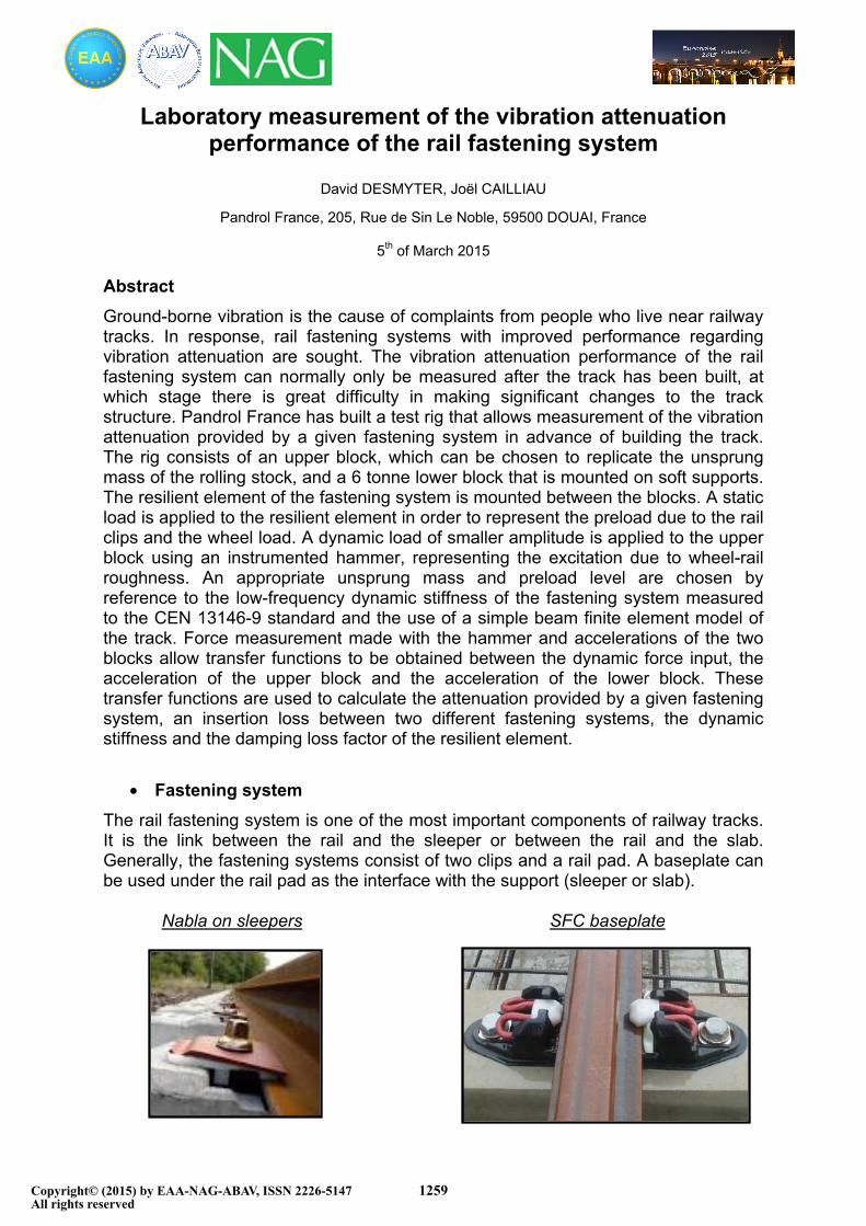
The rail fastening system is one of the most important components of railway tracks. It is the link between the rail and the sleeper or between the rail and the slab. Generally, the fastening systems consist of two clips and a rail pad. A baseplate can be used under the rail pad as the interface with the support (sleeper or slab).
Nabla on sleepers SFC baseplate
Copyright© (2015) by EAA-NAG-ABAV, ISSN 2226-5147All rights reserved
1259

The rail pad is compressed by the 2 clips with a typical clamping force of 20 kN per rail seat. When the train is passing, the distributed wheel load causes additional compression of rail pad. The additional force acting on the rail pad depends on the sleeper spacing, the rail pad low-frequency dynamic stiffness and the wheel load. Following the CEN 13146-9, it is possible to measure the low frequency dynamic stiffness of rail pads or assemblies.
• Track parameters
For a specific project, rail section, sleeper spacing, axle load and low-frequency dynamic rail pad stiffness (Kdyn) are known. This information, together with the use of a simple beam element model allows the calculation of the distribution load factor (ν). Such a calculation is described below for a stiff support and for a soft support. The soft support is the resilient element which will improve vibration attenuation relative to the stiff support.
Simple beam element model of track
Q = Static wheel load R20 = Reaction in the support #20 directly beneath the wheel load Q ν = Q / R20 RAIL : 54E1
Load factor (ν)
The unsprung mass is the mass of the wheel and axle box. 1000 Kg is a typical value of unsprung mass per wheel.
Low frequency dynamic stiffness Support spacing : 600 mm
Stiff rail pad 150 MN/m 1,80
Soft assembly 25 MN/m 2,77
Q
EuroNoise 201531 May - 3 June, Maastricht
D. Desmyter et al.: Laboratory...
1260

• Test rig description
The test rig consists in modeling the dynamic
behavior of the track with 2 degrees of
freedom structure. The first elastic level is a
monolithic concrete mass of 6T supported by
4 soft supports (Fig. 9). The stiffness of each
support is about 1 MN/m. The resonance
frequency of the concrete structure moving
as a rigid structure on the 4 soft supports is 4
Hz (Fig. 10). The first internal elastic
resonance frequency of the concrete mass is
412 Hz (Fig. 11). The test rig therefore
provides a suitable frequency range for these
measurements with regards to ground
vibration and ground borne noise.
The second elastic level is the tested rail
placed between the monolithic concrete mass
(M) and the “equivalent” unsprung mass (m)
made of steel. The “equivalent” unsprung
mass is the unsprung mass of one wheel
divided by the distribution load factor (ν)
previously calculated with the beam element
model.
Fig. 10 – FRF of the concrete mass
Fig. 11 – Accelerance of concrete mass
4 Hz 412 Hz
455 Hz1/m = 0,000163
m = 6 060 Kg
Fig. 9 - Concrete mass on very soft supports
Monolithic concrete mass
Soft support
EuroNoise 201531 May - 3 June, Maastricht
D. Desmyter et al.: Laboratory...
1261

m
M
Two springs with stiffness of 0.7 MN/m are fixed between the “equivalent” unsprung mass and the concrete mass. They are used to apply the static load on the rail pad. Strain gauges are fixed on springs to control the force in the springs. Calibration curve between the force in the spring and strain has been determined previously. The static load applied by the two springs is equal to the clip load plus the distributed wheel load acting on the rail pad when the wheel is above a support. Under such conditions, the reference rail pad and the tested assembly are under the same conditions as on track. The static load on the fastener is function of the unsprung mass plus sprung mass of the train.
Fig.12 – Equivalent U.M. with springs on the concrete mass
• Mitigation measurement
An instrumented impact hammer of 1.1 Kg is used to enter a vertical force of approximately 6 kN on the “equivalent” unsprung mass (m). Vertical accelerations of the concrete mass (M) and the steel mass (m) are recorded. Transfer functions between the accelerations and the applied force are calculated. The measurement is made for stiff rail support and for soft support. Insertion loss mitigation and transmission loss mitigation can be found in the range of frequency between 20 Hz and 200 Hz.The measurement is made on the stiff rail pad and the soft assembly.
TRACK
PARAMETERS
Rail 54E1
Support spacing 600 mm
Unsprung mass 1150 Kg
Stiff rail pad (CEN 13146-9 low frequency dynamic stiffness) 150 MN/m
Soft assembly (CEN 13146-9 low frequency dynamic stiffness) 25 MN/m
TEST RIG
PARAMETERS
Equivalent Unsprung mass for stiff rail pad 671 Kg
Equivalent Unsprung mass for soft assembly 448 Kg
Static load including clip load on stiff pad 52 kN
Static load without clip load on soft assembly (*) 20 kN
Fig. 13 – Input data for the measurement
(*) The tested assembly is made of 2 cast iron plates separated by a resilient rubber element. The clips
are fixed on the top plate without rail pad. It is the reason why the clip load is not included in the
static load.
Rail pad or assembly
Spring to apply static load
EuroNoise 201531 May - 3 June, Maastricht
D. Desmyter et al.: Laboratory...
1262

Fig. 14 – FRF (concrete block acceleration / Force) and Insertion loss mitigation curves
The insertion loss mitigation measured with the test rig between the stiff rail pad and the soft assembly is 3.2 dB in the range of frequency 20-200 Hz. The transmission loss mitigation is 42.2 dB for the stiff rail pad and 51.9 dB for the soft assembly between 20 and 200 Hz. In track measurements made under traffic have been shown that fastening systems with low frequency dynamic stiffness of 25 MN/m provide an insertion loss mitigation higher than 10 dB in this range of frequency (Fig.16) [1]. One reason which could explain the difference between insertion loss mitigation measured with the test rig and the insertion loss mitigation measured on track is that the energy introduces in the test rig with the impact hammer is not representative of the energy input to the rail on track. The energy input to the rail at low frequencies may be less than the energy entering in the rail at high frequency. It would mean more energy entering in the fastening system at resonance frequency of the stiff pad and less energy entering in the fastening system at resonance frequency of the soft assembly. The wheel / rail interaction and excitation by roughness was investigated [2]. On the graph bellow, the prediction of the contact force shows that there is less force input to the rail at frequencies lower than 70 Hz. This correlated with our hypothesis.
Fig. 15 – Estimated contact force per unit roughness. Taken from [2]
Fig. 16 – Comparison between ballasted track and soft slab track under traffic
67,5 Hz 144,5 Hz
86 Hz
EuroNoise 201531 May - 3 June, Maastricht
D. Desmyter et al.: Laboratory...
1263
New investigations have to be done to understand the real wheel/rail contact forces more fully. The amplitude of the contact force is an important parameter which may have an influence on the rail pad dynamic stiffness too. When the real wheel/rail contact forces are known, a shaker will be used in place of the impact hammer. This will allow control of the amplitude of the force entering the equivalent unsprung mass as a function of the frequency.
• High frequency stiffness and loss factor measurements
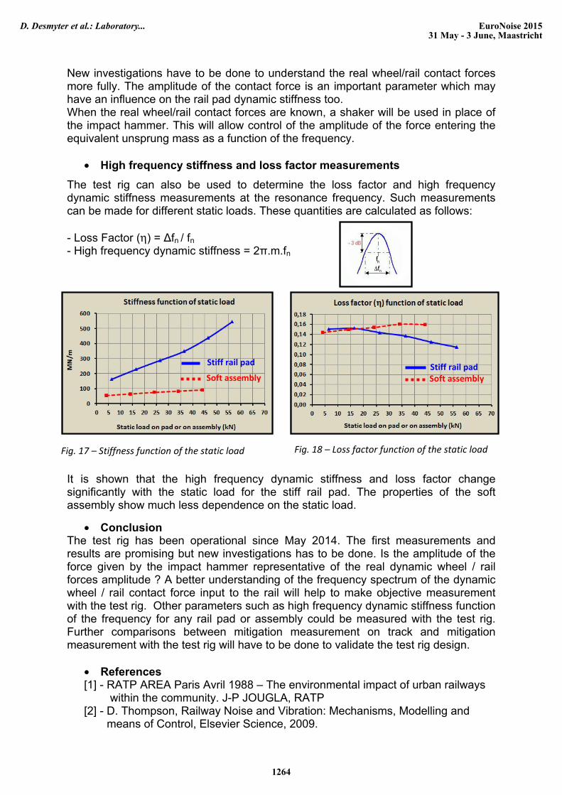
The test rig can also be used to determine the loss factor and high frequency dynamic stiffness measurements at the resonance frequency. Such measurements can be made for different static loads. These quantities are calculated as follows: - Loss Factor (η) = ∆fn / fn - High frequency dynamic stiffness = 2π.m.fn
It is shown that the high frequency dynamic stiffness and loss factor change significantly with the static load for the stiff rail pad. The properties of the soft assembly show much less dependence on the static load.
• Conclusion The test rig has been operational since May 2014. The first measurements and results are promising but new investigations has to be done. Is the amplitude of the force given by the impact hammer representative of the real dynamic wheel / rail forces amplitude ? A better understanding of the frequency spectrum of the dynamic wheel / rail contact force input to the rail will help to make objective measurement with the test rig. Other parameters such as high frequency dynamic stiffness function of the frequency for any rail pad or assembly could be measured with the test rig. Further comparisons between mitigation measurement on track and mitigation measurement with the test rig will have to be done to validate the test rig design.
• References [1] - RATP AREA Paris Avril 1988 – The environmental impact of urban railways within the community. J-P JOUGLA, RATP [2] - D. Thompson, Railway Noise and Vibration: Mechanisms, Modelling and means of Control, Elsevier Science, 2009.
Fig. 17 – Stiffness function of the static load
Stiff rail pad
Soft assembly
Fig. 18 – Loss factor function of the static load
Stiff rail padSoft assembly
EuroNoise 201531 May - 3 June, Maastricht
D. Desmyter et al.: Laboratory...
1264