Embed Size (px)
Citation preview
Laboratory Facilities
www.cfertech.com
Printed in Canada 2019
Eric Amphlett [E] ManagerInfrastructure & Systems
[email protected][T] 780.450.8989 x234[F] 780.450.3700
LOAD FRAMES C-FER operates a variety of large-scale servo-hydraulic load frames to simulate complex loading scenarios representative of field conditions.
Auxiliary Equipment Example Tests
• Electric resistive or inductive heating systems • Hydrotest equipment• High pressure cooling system • Leak detection equipment• Bending systems• Torsion systems• Pass-through pressure vessels
• ISO / Thermal well casing connections • Biaxial Tension/Compression of line pipe• Four-point bend of line pipe • Wave loading on composite risers• Makeup of subsea pipeline collets• Drilling top drive assemblies • Crack growth in aerospace structural panels• Seismic building dampers
System Universal Testing System Tubular Testing System
Connection Testing System
Horizontal Testing System
Maximum Specimen Dimensions
Length 6 mBase 2 x 18 m
Length 15 mDiameter 1.5 m
Length 11.6 mBase 2 x 2 m
Length 5.5 mDiameter 1.2 m
System can be reconfigured to accept larger specimens
Maximum Load
Compression 15 MNTension 15 MNDynamic 5 MN
Structurally capable of 22 MN with additional actuators
Compression 15 MNTension 15 MN
Compression 15 MNTension 15 MN
Tension 71 MN
Frame Orientation
Vertical Vertical Vertical Horizontal
Special Features
Maximum stroke rate 100 mm/sec
Bending capacity of 27 MNm
Bending capacity 27 MNm
Bending capacity 8 MNm
Sour service capability
Energy dissipation system for destructive testing
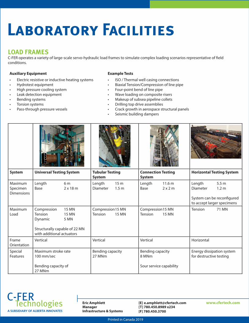
Laboratory FacilitiesDEEPWATER EXPERIMENTAL CHAMBER
C-FER’s Deepwater Experimental Chamber (DEC) enables full-scale testing of deepwater pipeline and production equipment. The vessel is unique because of the size, pressure rating and ease of access.
Equipped with quick release end caps, the vessel ensures rapid installation and removal of equipment, reducing both testing time and cost.
Full-scale tests with comprehensive instrumentation, control and video monitoring minimizes the potential for costly equipment failures in deep water.
• Working pressures to 55 MPa (8,000 psi)• 10.7 m (35 ft) long with a 1.22 m (4 ft) diameter• Equipped with internal rams and reaction frames to apply
tension, compression, torsion and bending loads to specimens while under pressure
• Full–scale pipeline testing at working pressures, both internally and externally
• Rapid installation and removal of test specimens and assemblies
• Internal video monitoring• Accommodates hydraulic, electrical, video and
instrumentation leads
www.cfertech.com
Printed in Canada 2019
Eric Amphlett [E] ManagerInfrastructure & Systems
[email protected][T] 780.450.8989 x234[F] 780.450.3700
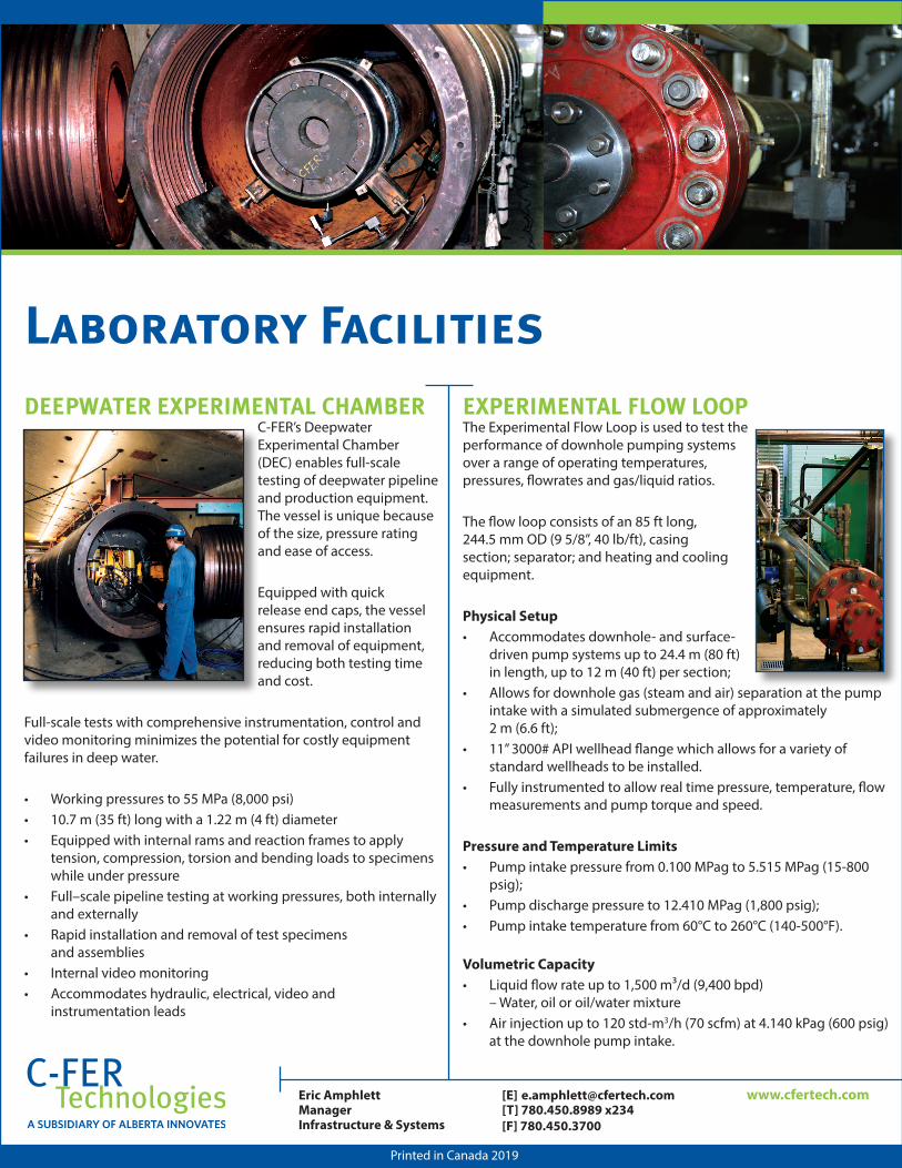
EXPERIMENTAL FLOW LOOP The Experimental Flow Loop is used to test the performance of downhole pumping systems over a range of operating temperatures, pressures, flowrates and gas/liquid ratios.
The flow loop consists of an 85 ft long, 244.5 mm OD (9 5/8”, 40 lb/ft), casing section; separator; and heating and cooling equipment.
Physical Setup• Accommodates downhole- and surface-
driven pump systems up to 24.4 m (80 ft) in length, up to 12 m (40 ft) per section;
• Allows for downhole gas (steam and air) separation at the pump intake with a simulated submergence of approximately 2 m (6.6 ft);
• 11” 3000# API wellhead flange which allows for a variety of standard wellheads to be installed.
• Fully instrumented to allow real time pressure, temperature, flow measurements and pump torque and speed.
Pressure and Temperature Limits• Pump intake pressure from 0.100 MPag to 5.515 MPag (15-800
psig);• Pump discharge pressure to 12.410 MPag (1,800 psig);• Pump intake temperature from 60°C to 260°C (140-500°F).
Volumetric Capacity• Liquid flow rate up to 1,500 m³/d (9,400 bpd)
– Water, oil or oil/water mixture• Air injection up to 120 std-m3/h (70 scfm) at 4.140 kPag (600 psig)
at the downhole pump intake.
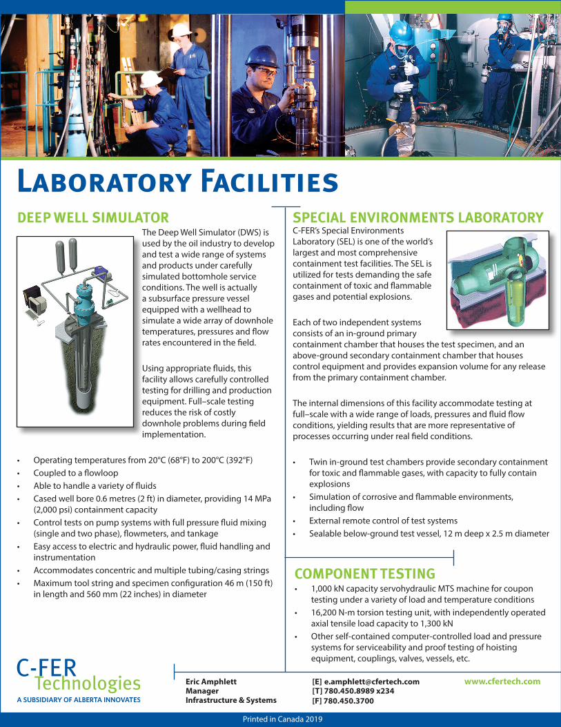
Laboratory FacilitiesDEEP WELL SIMULATOR
The Deep Well Simulator (DWS) is used by the oil industry to develop and test a wide range of systems and products under carefully simulated bottomhole service conditions. The well is actually a subsurface pressure vessel equipped with a wellhead to simulate a wide array of downhole temperatures, pressures and flow rates encountered in the field.
Using appropriate fluids, this facility allows carefully controlled testing for drilling and production equipment. Full–scale testing reduces the risk of costly downhole problems during field implementation.
• Operating temperatures from 20°C (68°F) to 200°C (392°F)• Coupled to a flowloop• Able to handle a variety of fluids• Cased well bore 0.6 metres (2 ft) in diameter, providing 14 MPa
(2,000 psi) containment capacity• Control tests on pump systems with full pressure fluid mixing
(single and two phase), flowmeters, and tankage• Easy access to electric and hydraulic power, fluid handling and
instrumentation• Accommodates concentric and multiple tubing/casing strings• Maximum tool string and specimen configuration 46 m (150 ft)
in length and 560 mm (22 inches) in diameter
SPECIAL ENVIRONMENTS LABORATORY C-FER’s Special Environments Laboratory (SEL) is one of the world’s largest and most comprehensive containment test facilities. The SEL is utilized for tests demanding the safe containment of toxic and flammable gases and potential explosions.
Each of two independent systems consists of an in-ground primary containment chamber that houses the test specimen, and an above-ground secondary containment chamber that houses control equipment and provides expansion volume for any release from the primary containment chamber.
The internal dimensions of this facility accommodate testing at full–scale with a wide range of loads, pressures and fluid flow conditions, yielding results that are more representative of processes occurring under real field conditions.
• Twin in-ground test chambers provide secondary containment for toxic and flammable gases, with capacity to fully contain explosions
• Simulation of corrosive and flammable environments, including flow
• External remote control of test systems• Sealable below-ground test vessel, 12 m deep x 2.5 m diameter
www.cfertech.com
Printed in Canada 2019
Eric Amphlett [E] ManagerInfrastructure & Systems
[email protected][T] 780.450.8989 x234[F] 780.450.3700
COMPONENT TESTING• 1,000 kN capacity servohydraulic MTS machine for coupon
testing under a variety of load and temperature conditions• 16,200 N-m torsion testing unit, with independently operated
axial tensile load capacity to 1,300 kN• Other self-contained computer-controlled load and pressure
systems for serviceability and proof testing of hoisting equipment, couplings, valves, vessels, etc.