Embed Size (px)
Citation preview

Laboratory:
Designing passive and active analog filters
Authors:
Michał Bujacz
Jan Szajdziński

Strona:2/14
1. Introduction The goal of this exercise is to practice designing, constructing and testing simple analog filters. To complete all the tasks you will need basic knowledge of signal processing, electronics, and pspice simulation software.
1.1 Theoretical review
The pass band of a filter is defined as the set of frequencies for which the attenuation is less than
3dB (which is ½ of the input power or 1
√2 ≈ 70,7% of its amplitude).
Stop band of a filter is the set of frequencies where the attenuation is greater than an agreed upon value (usually 20dB). Transition band are the frequencies between the stop and pass bands. Cutoff frequency – depending on the type a filter can have one or two cutoff frequencies designating the end (or ends) of the pass band
The slope of the characteristic is expressed (in dB) as the loss of amplitude per a decade (order) of
frequencies.

Strona:3/14
The main types of filters divided by frequency characteristics are: − high pass − low pass − band pass − band stop − octave filter (a band pass filter with
cutoff frequencies related by fL=2*fH)
Theoretical ideal filters:
We can also divide filters by the singal processing method: analog filters (work on real continuous signals) and digital filters (work on sampled quantitized filtres) Analog filters can be:
− passive – consisting of passive elements only – resistors, capacitors and coils − active – use transistors and op. amps
Strona:4/14
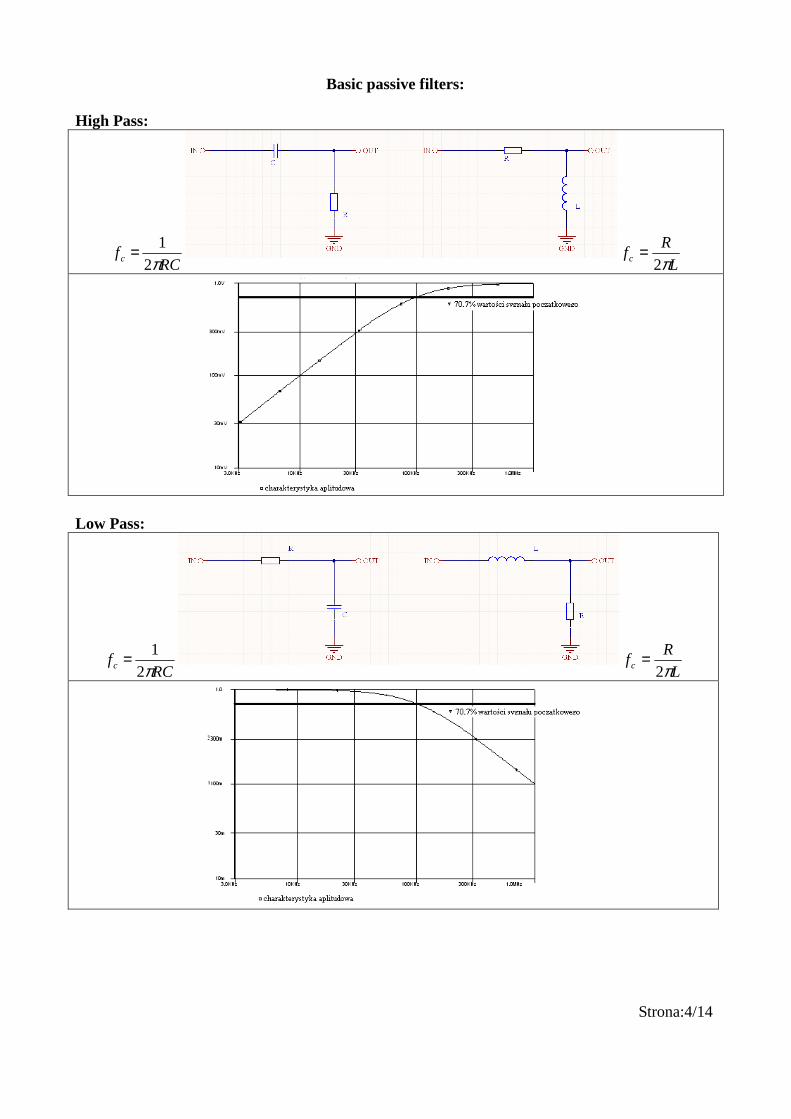
Basic passive filters: High Pass:
RCfc π2
1=L
Rfc π2
=
Low Pass:
RCfc π2
1=L
Rfc π2
=

Strona:5/14
Basic active filers (with capacitors) LP HP
Cutoff frequencies: Amplification in pass-band: Frequency characteristics: HP LP
K=
R2
R1
K=
R2
R1
f odc=1
2π R2Cf odc=
12π R1C

Strona:6/14
Combining filters to obtain band pass or band stop filters: Band stop – combine in parallel, frequencies outside the stopband will pass through:
Band pass – series, frequencies common for both passbands will pass through:

Strona:7/14
2.2. Generic advice for all exercises:
Connecting power for a symmetric +/- 5V supply:
Zdj.1 Available connectors: Stereo jack input Mono jack input Stereo jack output 3 banana-goldpin cables for power supply short circuiting wire to connect the symmetrical supply 2x jack – jack cables For mono signals (microphone, guitar) always use mono input to avoid interference. BLACK pins are alawys GND. RED color is usually the RIGHT channel BLUE is the LEFT channel Bread board advice: − The bread board allows connecting of most 100mils (2,54mm) raster devices − The connections between bread board sockets are printed on the reverse of the boards − Use the jack ports for input and output from the bread boards − Use the staples as simple jumpers between existing bread board conductive paths − Bread boards should not be used for high frequency or high power circuits due to their inherent high parasitic capacitances and risk of melting from large currents.

Strona:8/14
2. Passive filter exercises:
Exercise 0 (tutorial) Task: Design an HP 1kHz passive analog filter using a 22nF capacitor and a 10k pot. 1. Run pspice (start->programy->PSpice Student->Schematics) and set it up as on the screenshot:
2. Add the necessary elements (button: ): - capacitor (C1), resistor (R1), signal source (VSIN) and ground (GND_EARTH) - you can rotate elements using ctrl+r - the resistor value in the screenshots is not the correct one!

Strona:9/14
3. Set the values for the components by doublecliking on their symbols, then click Save Attr: - 22n for the capacitor
- calculate the value for the resistor using formulas from the introduction:
- for the source:

Strona:10/14
4. Connect elements using
5 Add a voltage probe
6 Run simulation
After the simulation change the scales to logarythmic by doubleclicking on the axes.. Add a line for the 70% value of the pass-band signal or 70% value of the input signal. What’s the difference? Explain in the report.

Strona:11/14
7. Connect the simulated schematic using the bread board. Connect the headphone output from the PC to your bread board input. Run the SweepGen software: (it should be on the desktop ../pulpit/akustyka/generator.exe). Setup the program as below:
Connect the oscilloscope and using the potentiometer try to obtain the desired -3dB output at the cutoff frequency. Measure the resistance the pot was set to using a multimeter. How does it compare to the value from the simulation? 8 Plot an approximated frequency characteristic after measuring the output for several different frequencies.

Strona:12/14
9 Connect headphones to the output, listen to a frequency sweep
and a few songs on youtube to hear what happens as you adjust the pot.
Strona:13/14
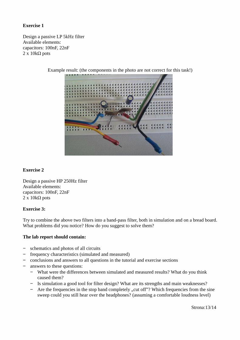
Exercise 1 Design a passive LP 5kHz filter Available elements: capacitors: 100nF, 22nF 2 x 10kΩ pots
Example result: (the components in the photo are not correct for this task!)
Exercise 2 Design a passive HP 250Hz filter Available elements: capacitors: 100nF, 22nF 2 x 10kΩ pots Exercise 3: Try to combine the above two filters into a band-pass filter, both in simulation and on a bread board. What problems did you notice? How do you suggest to solve them? The lab report should contain: − schematics and photos of all circuits − frequency characteristics (simulated and measured) − conclusions and answers to all questions in the tutorial and exercise sections − answers to these questions:
− What were the differences between simulated and measured results? What do you think caused them?
− Is simulation a good tool for filter design? What are its strengths and main weaknesses? − Are the frequencies in the stop band completely „cut off”? Which frequencies from the sine
sweep could you still hear over the headphones? (assuming a comfortable loudness level)

Strona:14/14
− Is a bread board a good tool for prototyping circuits highly dependant on precise capacitor values?
− What problems do you encounter when trying to design narrow pass-band passive fitlers?
4. Active fitler exercises
Exercise 4 Design an active HP(250Hz) filter using an lm324 op-amp. Calculate theoretical values, run a simulation, connect the bread board. Remember to connect symmetrical voltage to the op-amp as instructed on page 7. Compare the frequency characteristic to the passive filter. Check if the filter has a second cut-off frequency? Why? Exercise 5 Design, simulate and construct an active version of the filter in exercise 3. Compare the active and passive versions. The lab report should contain: − schematics and photos of all circuits − frequency characteristics (simulated and measured) − conclusions and answers to all questions in the tutorial and exercise sections − answers to these questions:
− What’s the effect when R1 and R2 are the same? When should you use different ones and why?
− What’s the effect of separate values: R1,R2, C and their ratios? − What determines the upper limit of the pass band for an active filter?